JP4625796B2 - Multiple arc tunnel connection structure and construction method - Google Patents
Multiple arc tunnel connection structure and construction method Download PDFInfo
- Publication number
- JP4625796B2 JP4625796B2 JP2006281642A JP2006281642A JP4625796B2 JP 4625796 B2 JP4625796 B2 JP 4625796B2 JP 2006281642 A JP2006281642 A JP 2006281642A JP 2006281642 A JP2006281642 A JP 2006281642A JP 4625796 B2 JP4625796 B2 JP 4625796B2
- Authority
- JP
- Japan
- Prior art keywords
- tunnel
- steel
- joint
- arc
- tunnels
- Prior art date
- Legal status (The legal status is an assumption and is not a legal conclusion. Google has not performed a legal analysis and makes no representation as to the accuracy of the status listed.)
- Active
Links
Images


Description
本発明は、少なくとも3連以上の多連円弧状トンネルにおけるトンネルと接合躯体の接続構造と多連円弧状トンネルの施工方法に関するものである。 The present invention relates to a connection structure between a tunnel and a joint housing in a multiple arc-shaped tunnel of at least three or more and a construction method of the multiple arc-shaped tunnel.
地下道路トンネルの分合流部をはじめとして地中にてトンネルを接合することによって大断面トンネルを施工する方法として、従来は大規模な開削工法が適用されてきたが、用地確保、地上交通への影響、工期の長期化とそれに伴なう工費の増大などから、より安全かつ経済的なトンネル接合方法が切望されており、建設各社が検討/開発を進めている。 As a method of constructing large section tunnels by joining tunnels in the ground including the junction of underground road tunnels, large-scale excavation methods have been applied in the past. Due to the impact, prolongation of the construction period and the accompanying increase in construction costs, a safer and more economical tunnel joining method is desired, and construction companies are studying / developing.
併設する2つのトンネルを接続して大断面トンネルを構築する方法としては、例えば図13に示すように多様な施工形態が考えられる。図13aは、大小2つの先行トンネルa,b双方を内包する大断面のトンネルcを構築するものであり、円形断面とすることで発生断面力(例えば曲げモーメント)を極力抑えることができるが、施工が極めて困難であること、このような円形断面では、その上下に存在ないしは計画される他のトンネルとの干渉の可能性が高くなって実用性に乏しいという問題がある。また、図13bは、その断面を楕円形の大断面トンネルdとすることで発生断面力の抑制と図13aの円形断面よりは他のトンネルとの干渉の可能性を低減できる一方で、やはり施工が極めて困難であることと他のトンネルとの干渉の可能性が依然として残ってしまうという問題がある。 As a method for constructing a large-section tunnel by connecting two adjacent tunnels, for example, various construction modes are possible as shown in FIG. FIG. 13a is a construction of a tunnel c having a large cross section that encloses two large and small preceding tunnels a and b, and the generated cross-sectional force (for example, bending moment) can be suppressed as much as possible by using a circular cross section. There is a problem that the construction is extremely difficult, and such a circular cross section has a high possibility of interference with other tunnels that are present or planned above and below it and are not practical. Further, FIG. 13b shows that the cross-section of the tunnel is an elliptical large-section tunnel d, so that the generated cross-sectional force can be suppressed and the possibility of interference with other tunnels can be reduced compared to the circular section of FIG. 13a. However, there is still a problem that the possibility of interference with other tunnels still remains.
一方、図13cに示す構造は、双方のトンネルa,bの上下部を水平な接合躯体e1,e2(切開き部ともいう)にて接続するものであり、上下に存在する他のトンネルとの干渉の可能性がなくなり、施工の実用性も高い構造である。しかし、接合躯体e1,e2が水平であることから、それらに生じる発生断面力が極めて大きくなり、構造上不経済な断面になることは明らかであり、それが大深度地下トンネルの場合にはその不経済性が顕著になり、工費の高騰や施工困難性が齎される。なお、この図13cの構造を具備する大断面トンネルの接合構造にかかる技術が特許文献1に開示されている。
On the other hand, in the structure shown in FIG. 13c, the upper and lower portions of both tunnels a and b are connected by horizontal joint frames e1 and e2 (also referred to as slits), and the other tunnels above and below are connected. The structure eliminates the possibility of interference and is highly practical for construction. However, since the joint frames e1 and e2 are horizontal, it is clear that the generated cross-sectional force is extremely large, resulting in a structurally uneconomic cross section. Ineconomical property becomes prominent, and construction cost increases and construction difficulty is jeopardized. A technique relating to a junction structure of a large-section tunnel having the structure of FIG. 13c is disclosed in
本発明は、上記する問題に鑑みてなされたものであり、大断面トンネルを多連円弧状トンネルとし、先行施工される併設した円形断面トンネル同士を繋ぐ接合躯体を可及的に経済的な断面とすることのできる多連円弧状トンネルの接続構造および施工方法を提供することを目的とする。 The present invention has been made in view of the above problems, and a large cross-section tunnel is a multi-circular arc tunnel, and a joint housing that connects the pre-constructed circular cross-section tunnels to each other is as economical as possible. It is an object of the present invention to provide a connection structure and construction method for a multiple arc-shaped tunnel that can be configured as follows.
前記目的を達成すべく、本発明による多連円弧状トンネルの接続構造は、併設するトンネルと、双方のトンネルを繋ぐ接合躯体と、からなる少なくとも3連以上の多連円弧状トンネルにおいて、トンネルと接合躯体の接続構造であって、トンネルを構成する鋼製セグメントである鋼殻の一部と鉄筋コンクリート造の接合躯体とが、該接合躯体の円弧に沿う鋼製の接合ピースを介して接続されていることを特徴とするものである。 In order to achieve the above-mentioned object, the connection structure of the multiple arc-shaped tunnel according to the present invention includes at least three or more multiple arc-shaped tunnels comprising an adjacent tunnel and a joint housing connecting both tunnels. A connection structure of a joint frame, in which a part of a steel shell that is a steel segment constituting a tunnel and a reinforced concrete joint frame are connected via a steel joint piece along an arc of the joint frame. It is characterized by being.
多連円弧状トンネルとは、例えば2つの円形トンネルと該トンネル同士を上下の円弧状の接合躯体にて繋いでなるトンネルのことであり、そのほかにも、間隔を置いて併設する3つの円形トンネル(例えば第1トンネル、第2トンネル、第3トンネルという)において、第1トンネルと第2トンネル、第2トンネルと第3トンネルをそれぞれ上下の円弧状の接続部にて繋いでなるトンネルなどを意味している。また、この施工方法は、道路トンネルにおける2つ以上のトンネルが接続する区間となる分合流部の拡幅部や、地下鉄路線と駅舎との接続部、各種地下施設を収容するための広範な地下空間等がその用途である。ここで、円弧状の接続躯体とは、一つの曲率を有する円弧のほか、多数の曲率が連続して組み合わされた形状、さらには扁平した楕円形状などの接続躯体を意味している。 A multiple arc tunnel is a tunnel formed by connecting two circular tunnels to each other by upper and lower arc-shaped joints, and in addition, three circular tunnels provided at intervals. (For example, the first tunnel, the second tunnel, and the third tunnel) In the first tunnel and the second tunnel, the second tunnel and the third tunnel are connected by upper and lower arc-shaped connection portions, respectively. is doing. In addition, this construction method has a wide underground space to accommodate the widened portion of the junction and junction where the two or more tunnels in the road tunnel connect, the connection between the subway line and the station building, and various underground facilities. Etc. are its uses. Here, the arc-shaped connecting housing means a connecting housing such as a circular arc having one curvature, a shape in which a large number of curvatures are continuously combined, and a flat elliptical shape.
まず、併設する被接続トンネルをシールド工法もしくは推進工法にて例えば2台の掘進機を使用しながら平行して施工し、もしくは1台の掘進機を使用して順次施工する。このトンネルは鋼製セグメントである鋼殻や鋼製函体などから構成されており、たとえば鋼殻には予めパイプルーフ挿通用の挿通孔を設けておき、双方のトンネル間にパイプルーフ用の鋼管をトンネル長手方向に所定間隔で掛け渡し、このパイプルーフ直下を掘削するとともに鉄筋コンクリート造の接合躯体を構築し、トンネルが該接合躯体と通じる部分の鋼殻を撤去することにより、多連円弧状トンネルが構築される。また、地山強度が十分な場合は接合躯体の構築に先行して行う掘削は、山岳工法によることもある。接合躯体が円弧状であることにより、地盤条件によっては図13cに示す形状の大断面トンネルに比して接合躯体に生じる断面力を40%程度も低減することができ、さらには、接合躯体の形状(構造)をよりコンパクトにでき、トンネル内に配設される例えばダクトスペースや標識設置スペースを十分に確保することもできる。 First, the connected tunnel to be provided is constructed in parallel using, for example, two excavators by the shield method or the propulsion method, or sequentially by using one excavator. This tunnel is composed of steel shells and steel boxes, which are steel segments. For example, a steel pipe for pipe roof is provided between both tunnels by providing a hole for inserting a pipe roof in advance in the steel shell. Is tunneled in the longitudinal direction of the tunnel, excavated directly under the pipe roof, constructed a reinforced concrete joint housing, and removed the steel shell of the part where the tunnel communicates with the joint housing, thereby creating a multiple arc tunnel Is built. In addition, when the natural ground strength is sufficient, the excavation performed prior to the construction of the jointed frame may be based on the mountain method. Due to the arc shape of the joint housing, the cross-sectional force generated in the joint housing can be reduced by about 40% compared to the large cross-section tunnel having the shape shown in FIG. 13c depending on the ground conditions. The shape (structure) can be made more compact, and for example, a duct space and a sign installation space disposed in the tunnel can be sufficiently secured.
本発明のトンネル鋼殻と接合躯体の接続構造では、接合躯体の円弧に沿う鋼製の接合ピースを介してトンネル鋼殻と接合躯体の双方を接続するものである。具体的には、接合躯体の有する円弧形状の輪郭を具備する鋼製の接合ピースを用意し、該接合ピースの一端はトンネル鋼殻にボルト接合ないしは溶接等にて接合し、接合ピースの他端は鉄筋コンクリート造の接合躯体内部に定着させるものである。 In the connection structure of the tunnel steel shell and the joining housing of the present invention, both the tunnel steel shell and the joining housing are connected via a steel joining piece along the arc of the joining housing. Specifically, a steel joining piece having an arc-shaped contour of the joining housing is prepared, and one end of the joining piece is joined to a tunnel steel shell by bolt joining or welding, and the other end of the joining piece is prepared. Is fixed inside the reinforced concrete joint.
まず、接合躯体が円弧状を呈することでこの接合躯体にはアーチ効果が期待でき、接合躯体に生じる発生断面力を極力抑えることができるとともに、上下の他のトンネルとの干渉の可能性も極めて低くすることができる。 First, since the joint body has an arc shape, the joint body can be expected to have an arch effect, the cross-sectional force generated in the joint body can be suppressed as much as possible, and the possibility of interference with other upper and lower tunnels is extremely high. Can be lowered.
接合躯体の有する円弧形状の輪郭を具備する鋼製の接合ピースを使用することで、応力を接続部に局所的に集中させることなく、接合躯体からトンネル鋼殻へ応力を分散させることができる。したがって、この接合躯体およびトンネル鋼殻を経済的な断面とすることができ、工費を増大させることもない。また、接続部の構造が鋼製の接合ピースと、鉄筋コンクリートとからなるSC構造もしくはSRC構造を呈することで、高い接続強度を期待することができる。 By using the steel joining piece having the arc-shaped contour of the joining housing, the stress can be dispersed from the joining housing to the tunnel steel shell without locally concentrating the stress on the connecting portion. Therefore, the bonded housing and the tunnel steel shell can have an economical cross section, and the construction cost is not increased. Moreover, high connection strength can be expected because the structure of the connection portion exhibits an SC structure or SRC structure composed of a steel joining piece and reinforced concrete.
ここで、上記する接合ピースの一実施の形態として、この接合ピースを、鉛直方向に立設したウェブと該ウェブの上端から突出するフランジとからなる断面逆L型の2つの鋼材がウェブ同士を対向させた姿勢で配設されてなるユニット体から構成し、鋼材の一端部に固着されたプレートが鋼殻に固着された継手プレートに接合し、鋼材の他端部は接合躯体内部に定着した形態を適用することができる。 Here, as one embodiment of the above-mentioned joining piece, two steel materials having an inverted L-shaped cross section composed of a web erected in the vertical direction and a flange protruding from the upper end of the web are connected to each other. Consists of unit bodies arranged in an opposed posture, a plate fixed to one end of steel material is joined to a joint plate fixed to a steel shell, and the other end portion of the steel material is fixed inside the joint housing Forms can be applied.
この実施の形態では、汎用の鋼材を用いながら接合ピースの断面剛性を高めることができる。このユニット体は、双方の鋼材の対向したウェブ同士を接続部材で繋いで一体構造とすることもできるし、非接続構造であってもよい。このユニット体の下方にはフランジが存在しないことで、作業員がその下方からユニット体の端部とトンネル鋼殻側の継手プレートとを容易にボルト接合等することが可能となる。なお、接合ピースと継手プレートとの接合部(例えば高力ボルト接合)を接合躯体を構成する鉄筋コンクリートが巻き込んだ形態とすることで、接合躯体とトンネル鋼殻との接続強度をより高めることもできる。 In this embodiment, the cross-sectional rigidity of the joining piece can be increased while using a general-purpose steel material. The unit body may be formed as an integral structure by connecting the opposing webs of both steel materials with a connecting member, or may be a non-connected structure. Since there is no flange below the unit body, an operator can easily bolt the end of the unit body and the joint plate on the tunnel steel shell side from below. In addition, the connection strength of a joining frame and a tunnel steel shell can also be raised more by setting the joined part (for example, high-strength bolt joining) of a joining piece and a joint plate as the form in which the reinforced concrete which comprises a joining frame was wound. .
また、接合ピースの他の実施の形態として、この接合ピースを、鉛直方向に立設したウェブと該ウェブの上下端から同方向に突出する2つのフランジとからなる断面コの字型の2つの鋼材がウェブ同士を対向させた姿勢で配設されてなるユニット体から構成し、鋼材の一端部に固着されたプレートが鋼殻に固着された継手プレートに接合し、鋼材の他端部は接合躯体内部に定着した形態を適用することもできる。 As another embodiment of the joining piece, the joining piece is divided into two U-shaped cross sections each composed of a web erected in the vertical direction and two flanges projecting in the same direction from the upper and lower ends of the web. It consists of a unit body in which the steel material is arranged in a posture in which the webs are opposed to each other. The plate fixed to one end of the steel material is bonded to the joint plate fixed to the steel shell, and the other end of the steel material is bonded. A form fixed in the housing can also be applied.
この実施の形態においては、汎用の鋼材を用いて上記形態よりもより大きな断面剛性の接合ピースを得ることができる。本実施の形態においても、ユニット体を構成する双方の鋼材のウェブ同士を接続部材で繋いで一体構造とすることもできるし、非接続構造とすることもできる。また、断面コの字型の鋼材のうち、ユニット体の端部と継手プレートとの接合部近傍における下部フランジのみを取り除いた構造とすることで、上記形態と同様にその端部と継手プレートとを容易にボルト接合等することが可能となる。 In this embodiment, it is possible to obtain a joining piece having a larger cross-sectional rigidity than that of the above-described form using a general-purpose steel material. Also in the present embodiment, both steel webs constituting the unit body can be connected by a connecting member to form an integral structure, or a non-connected structure. Moreover, among the U-shaped steel materials having a cross-sectional shape, by removing only the lower flange in the vicinity of the joint between the end of the unit body and the joint plate, the end and the joint plate Can be easily bolted together.
また、本発明による多連円弧状トンネルは、上記するトンネル鋼殻と接合躯体の接続構造を具備することを特徴とするものである。 Moreover, the multiple arc-shaped tunnel according to the present invention is characterized by comprising the above-described connection structure of the tunnel steel shell and the joint housing.
接合躯体を鉄筋コンクリート造とすることでトンネル鋼殻と該接合躯体との誤差を容易に吸収することができる。すなわち、双方が鋼製部材からなる場合には、ボルト孔の位置合わせ等に手間が掛かり、施工効率の低下は否めない。また、接合躯体とトンネル鋼殻との接続部における発生断面力を可及的に抑制することができるため、接合躯体を経済的な断面とすることができることに加えて、トンネル自体の断面も経済的な断面とすることができ、工費の大幅な削減を図ることが可能となる。 An error between the tunnel steel shell and the joining housing can be easily absorbed by making the joining housing a reinforced concrete structure. That is, when both are made of steel members, it takes time to align the bolt holes and the like, and a reduction in construction efficiency cannot be denied. In addition, since the generated cross-sectional force at the connecting portion between the joint frame and the tunnel steel shell can be suppressed as much as possible, the cross-section of the tunnel itself can be made economical in addition to making the joint frame an economical cross-section. It is possible to achieve a cross section, and it is possible to significantly reduce the construction cost.
また、本発明による多連円弧状トンネルの施工方法は、併設するトンネルと、双方のトンネルを繋ぐ接合躯体と、からなる少なくとも3連以上の多連円弧状トンネルの施工方法であって、地中に併設するトンネルを構築する工程と、前記トンネルのうち前記接合躯体と接続される箇所の鋼殻に対して、該接合躯体の円弧に沿う鋼製の接合ピースを接続する工程と、前記接合ピースを巻き込みながら鉄筋コンクリート造の接合躯体を構築する工程と、一方のトンネルにおける他方のトンネル側の鋼殻を撤去する工程と、を少なくとも具備することを特徴とするものである。 The method for constructing a multi-arc arc tunnel according to the present invention is a method for constructing at least three or more multi-arc arc tunnels comprising an adjacent tunnel and a joint frame connecting both tunnels, A step of constructing a tunnel attached to the joint, a step of connecting a steel joining piece along an arc of the joining housing to a steel shell at a location connected to the joining housing of the tunnel, and the joining piece It comprises at least a step of constructing a reinforced concrete joint housing while entraining and a step of removing a steel shell on the other tunnel side in one tunnel.
以上の説明から理解できるように、本発明の多連円弧状トンネルの接続構造および施工方法によれば、トンネル鋼殻と鉄筋コンクリート造の接合躯体とを該接合躯体の有する円弧形状の輪郭を具備する鋼製の接合ピースにて接続することで、経済的な断面の多連円弧状トンネルとすることができ、かつ、接合強度の高いトンネルおよび接合躯体の接続構造を形成することができる。 As can be understood from the above description, according to the connection structure and construction method of the multiple arc-shaped tunnel of the present invention, the tunnel steel shell and the reinforced concrete structure are provided with an arc-shaped contour. By connecting with steel joining pieces, it is possible to form a multi-circular arc tunnel with an economical cross-section, and to form a connection structure of a tunnel and a joining housing with high joining strength.
以下、図面を参照して本発明の実施の形態を説明する。図1は本発明の3連円弧トンネルの一実施の形態の斜視図であり、図2,3はそれぞれ接合ピースの一実施の形態が鋼製セグメントであるトンネル鋼殻と接合している状況を示した斜視図である。図4は接合躯体の内部構造を示した縦断図であり、図5は接合躯体のうち、トンネル鋼殻と接合する部分の外観斜視図である。図7は本発明の3連円弧トンネルにおける曲げモーメント分布図であり、図8は従来の大断面トンネルにおける曲げモーメント分布図である。図9〜図12は順に本発明の施工方法の例を説明した図である。 Embodiments of the present invention will be described below with reference to the drawings. FIG. 1 is a perspective view of an embodiment of a triple arc tunnel according to the present invention, and FIGS. 2 and 3 each show a state in which an embodiment of a joining piece is joined to a tunnel steel shell which is a steel segment. It is the shown perspective view. FIG. 4 is a longitudinal sectional view showing the internal structure of the joint housing, and FIG. 5 is an external perspective view of a portion of the joint housing that joins the tunnel steel shell. FIG. 7 is a distribution diagram of the bending moment in the triple arc tunnel of the present invention, and FIG. 8 is a distribution diagram of the bending moment in the conventional large section tunnel. 9-12 is the figure explaining the example of the construction method of this invention in order.
図1は、本発明の接続構造を具備する3連円弧トンネルの断面図である。この3連円弧トンネル10は、鋼製セグメントである鋼殻S,…から構成される2つのシールドトンネル1,2が地盤G内に所定間隔を置いて構築され、このトンネル1,2がそれらの上下を円弧状の接合躯体3,4にて接続された態様で構成されている。これら2つのトンネル1,2は、2台のシールド機が平行して、または1台のシールド機が順次掘進しながら地盤G内に先行施工される。この3連円弧トンネル10が地下道の分合流部に適用される場合には、例えば相対的に大断面のトンネル1が本線地下トンネルであり、小断面のトンネル2がランプトンネルとなる。
FIG. 1 is a cross-sectional view of a triple arc tunnel having the connection structure of the present invention. In this
先行施工されたトンネル1,2の上下周辺の対応箇所には双方のトンネル間に不図示のパイプルーフがトンネル長手方向に亘って仮設され、パイプルーフを支保工として、パイプルーフで囲まれた地盤を掘削するとともに鉄筋コンクリート造の接合躯体3,4を構築し、さらには接合躯体3,4と通じるに障害となる箇所のトンネル1,2の鋼殻S,…を撤去することにより、3連円弧トンネル10が構築される。地山強度が十分な場合は、接合躯体3,4の構築に先行して行う掘削は、山岳工法によってもよい。
A pipe roof (not shown) is temporarily installed along the tunnel longitudinal direction between the two tunnels at the corresponding locations around the upper and lower sides of the
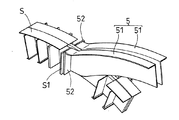
図2は、トンネル1,2と接合躯体3との接続部に設けられる鋼製の接合ピース5を示した図である。この接合ピース5は、鉛直方向に立設したウェブと該ウェブの上端から突出するフランジとからなる断面逆L型の2つの鋼材51,51がウェブ同士を対向させた姿勢で配設されてなるユニット体から構成される。鋼材51,51の一端には端部プレート52,52が固着されており、この端部プレート52,52と鋼製セグメントである鋼殻Sに固着された継手プレートS1が不図示のボルト(図4のボルトB)にて強固に接合される。
FIG. 2 is a view showing a
この鋼材51は、図1に示す接合躯体3,4の円弧形状に沿った線形を有しており、接合躯体3,4を構成する鉄筋コンクリート内に埋設されるようになっている。
This
一方、図3は、接合躯体の他の実施の形態を示しており、この接合ピース5Aは、鉛直方向に立設したウェブと該ウェブの上下端から同方向に突出する2つのフランジとからなる断面コの字型の2つの鋼材51A,51Aがウェブ同士を対向させた姿勢で配設されてなるユニット体から構成され、鋼材51Aの一端には継手プレートS1とボルト接合(図4のボルトB)される端部プレート52A,52Aが固着されている。
On the other hand, FIG. 3 shows another embodiment of the joining housing, and this joining
なお、これらの鋼材51,51同士、または鋼材51A,51A同士は、ともに不図示の接続部材にて繋がれて一体に形成されていてもよい。
In addition, these
図4は、接合躯体3の内部構造を示している。接合躯体3は、双方のトンネル1,2の鋼殻と直接接合される接合ピース5,5と、この接合躯体3の円弧形状に沿う方向の主鉄筋A1,…、トンネルの長手方向に延びる配力筋A2,…、およびそれらがコンクリートにて一体に形成された構造となっており、トンネル1,2との接続部においてはSC構造ないしはSRC構造を呈しており、その中央付近ではRC構造を呈した複合的な構造となっている。図5は、完成された接合躯体3がトンネル鋼殻Sと接合する部分の一部を示した斜視図である。
FIG. 4 shows the internal structure of the
さらに図6には、3連円弧トンネル10の内部構造の模式図を示している。2つのシールドトンネル1,2のそれぞれの上下の鋼製セグメントである鋼殻S,Sに対して、接合ピース5,5が接続され、この接合ピース5,5を巻き込んだ鉄筋コンクリート造の接合躯体3,4がトンネル1,2をその上下で繋いでいる。図からも明らかなように、円弧状の接合躯体3,4はトンネル1,2から上下に殆ど突出することがなく、したがって、3連円弧トンネル10の上下にある、ないしは計画されている他のトンネルと干渉する可能性は極めて低い。尤も、接続部をよりトンネル内部側に設定することで接合躯体3,4がトンネル1,2から突出しない構造とすることができ、この場合には他のトンネルとの干渉の可能性は完全になくなる。
Furthermore, in FIG. 6, the schematic diagram of the internal structure of the triple
この3連円弧トンネル10に発生する曲げモーメント分布図を図7に示しており、これは発明者等が任意の地盤条件にておこなった構造解析の結果によるものである。接合躯体と双方のトンネルとが剛結合にて繋がっていることで、接合躯体の端部の最大曲げモーメントの値M1とトンネル端部の最大曲げモーメントの値M2は同じとなるが、図7からも明らかなように、全体的に接合躯体に生じる曲げモーメントもトンネルに生じる曲げモーメントもおよそ同程度のモーメントの値を呈しており、接合躯体のみに過大な曲げモーメントが生じていない。これは、円弧状の接合躯体でトンネル間が繋がれた形状に起因するものである。このようにトンネル全体としてほぼ均等な断面力を呈することにより、接合躯体を過大な断面で構築する必要はなくなる。さらに、この接合躯体とトンネルとが接合ピースを介して接続されているため、接続部において十分な接続強度を確保することができる。より具体的には、接続部が円弧状で鋼製の接合ピースで構成されることで、接続部の曲げ剛性およびせん断剛性が高められるとともに、その線形から断面力のスムースな分散効果を期待することができる。
A distribution diagram of bending moment generated in the
一方、図8は、図13cに示す従来の大断面トンネルにおける曲げモーメント分布図を示している。図からも明らかなように、2つのトンネルを繋ぐ水平な接合躯体において、トンネルに比べて過大な曲げモーメント分布を呈している。これは接合躯体が水平であることに起因するものである。 On the other hand, FIG. 8 shows a bending moment distribution diagram in the conventional large-section tunnel shown in FIG. 13c. As is clear from the figure, the horizontal joint frame connecting the two tunnels exhibits an excessive bending moment distribution compared to the tunnel. This is due to the fact that the joint housing is horizontal.
次に、図9〜12に基づいて図1に示す3連円弧トンネル10の施工方法を説明する。なお、この3連円弧トンネル10は道路トンネルの分合流部(拡幅部)に適用される。
Next, a construction method of the
まず、図9に示すように、本線トンネルを構成する相対的に大断面のトンネル1とランプトンネルを構成する相対的に小断面のトンネル2を所定間隔をおいて先行施工する。
First, as shown in FIG. 9, a relatively large-
次いで、図10に移り、トンネルの長手方向の所定範囲、すなわちパイプルーフが施工される地盤領域に薬液を低圧浸透させて止水層8を造成する。双方のトンネル1,2における対応する鋼製セグメントである鋼殻S,Sの所定位置には不図示の鋼管挿通用の挿通孔が設けられており、パイプルーフ用鋼管6,7が一方のトンネルの挿通孔を介して地盤G内に挿入(押し出)されるとともに他方のトンネルの挿通孔を介して地盤G内から受け取られることで双方のトンネル間にパイプルーフが架設される。図10では、鋼管6が設置される部位を支保工Cで支保しながら、移動台座D上に載置された押し出し用マシンMにてトンネル2側からトンネル1側に向って湾曲した鋼管6を押し出している状況を示している。なお、下方に設置される鋼管7も同様の施工方法にて双方のトンネル間に仮設される。この鋼管6,7のより具体的な地盤内挿入方法は、鋼管6,7の先端開口部から不図示の回転ビットを挿通させ、この回転ビットに連通するノズルを介して高圧水を地盤内に噴射しながら地盤を穿孔して鋼管6,7を地盤内に挿入していく。
Next, moving to FIG. 10, the water-stopping
次いで、図11に移り、パイプルーフ施工後、トンネル1,2の上下周辺の対応箇所に接合ピース5,5を取り付け、この接合ピース5,5の周囲に円弧状で鉄筋コンクリート造の接合躯体3,4を構築する。次いで、トンネル1,2において接合躯体と連通するに障害となる箇所の鋼殻を撤去し、パイプルーフ6,7およびトンネル1,2で囲まれた領域の地盤を掘削する。
Next, moving to FIG. 11, after the pipe roof construction, the joining
図12は、3連円弧トンネル10の完成断面図である。最終的に道路床版が構築され、所定の施設機器が配設されて道路トンネル拡幅部が完成する。
FIG. 12 is a completed sectional view of the
本発明の多連円弧状トンネルの接続構造、具体的には鋼製セグメントである鋼殻と接合躯体との接続構造によれば、接合躯体が円弧状を呈していること、接続部がこの円弧状の鋼製接合ピースで構成されていることにより、接合躯体および鋼殻に生じる発生断面力を可及的に抑制することができ、経済的な断面を有するトンネルを形成することができるとともに、高強度の接続構造を得ることができる。 According to the connection structure of the multiple arc-shaped tunnel of the present invention, specifically, the connection structure of the steel shell, which is a steel segment, and the joint housing, the joint housing has an arc shape, and the connection portion has this circular shape. By being composed of an arc-shaped steel joining piece, it is possible to suppress as much as possible the generated cross-sectional force generated in the joint housing and the steel shell, and to form a tunnel having an economical cross-section, A high-strength connection structure can be obtained.
以上、本発明の実施の形態を図面を用いて詳述してきたが、具体的な構成はこの実施形態に限定されるものではなく、掘削方法にパイプルーフではなく山岳工法を適用する等、本発明の要旨を逸脱しない範囲における設計変更等があっても、それらは本発明に含まれるものである。 The embodiment of the present invention has been described in detail with reference to the drawings. However, the specific configuration is not limited to this embodiment, and the excavation method is not a pipe roof but a mountain method. Even if there is a design change or the like within a range not departing from the gist of the invention, they are included in the present invention.
1,2…トンネル、3,4…接合躯体、5,5A…接合ピース、51,51A…鋼材、6,7…パイプルーフ用鋼管、8…地盤改良層、10…3連円弧トンネル、S…鋼製セグメント(鋼殻)、S1…継手プレート、A1…接合躯体主鉄筋、A2…接合躯体配力筋、B…ボルト、G…地盤
DESCRIPTION OF
Claims (5)
トンネルを構成する鋼製セグメントである鋼殻の一部と鉄筋コンクリート造の接合躯体とが、該接合躯体の円弧に沿う鋼製の接合ピースを介して接続されていることを特徴とする、多連円弧状トンネルの接続構造。 In a multi-circular arc tunnel having at least three or more continuous tunnels, and a connection structure connecting at least three tunnels,
A part of a steel shell which is a steel segment constituting a tunnel and a reinforced concrete joint case are connected via a steel joint piece along an arc of the joint case. Arc tunnel connection structure.
地中に併設するトンネルを構築する工程と、
前記トンネルのうち前記接合躯体と接続される箇所の鋼殻に対して、該接合躯体の円弧に沿う鋼製の接合ピースを接続する工程と、
前記接合ピースを巻き込みながら鉄筋コンクリート造の接合躯体を構築する工程と、
一方のトンネルにおける他方のトンネル側の鋼殻を撤去する工程と、を少なくとも具備する、多連円弧状トンネルの施工方法。
It is a construction method of at least three or more continuous arc-shaped tunnels comprising an adjacent tunnel and a joint frame connecting both tunnels,
A process of constructing a tunnel attached to the ground,
Connecting the steel joining piece along the arc of the joint housing to the steel shell of the portion connected to the joint housing of the tunnel;
A step of constructing a reinforced concrete joint frame while entraining the joint piece;
A method of constructing a multiple arc-shaped tunnel, comprising at least a step of removing a steel shell on the other tunnel side in one tunnel.
Priority Applications (1)
| Application Number | Priority Date | Filing Date | Title |
|---|---|---|---|
| JP2006281642A JP4625796B2 (en) | 2006-10-16 | 2006-10-16 | Multiple arc tunnel connection structure and construction method |
Applications Claiming Priority (1)
| Application Number | Priority Date | Filing Date | Title |
|---|---|---|---|
| JP2006281642A JP4625796B2 (en) | 2006-10-16 | 2006-10-16 | Multiple arc tunnel connection structure and construction method |
Publications (2)
| Publication Number | Publication Date |
|---|---|
| JP2008095473A JP2008095473A (en) | 2008-04-24 |
| JP4625796B2 true JP4625796B2 (en) | 2011-02-02 |
Family
ID=39378600
Family Applications (1)
| Application Number | Title | Priority Date | Filing Date |
|---|---|---|---|
| JP2006281642A Active JP4625796B2 (en) | 2006-10-16 | 2006-10-16 | Multiple arc tunnel connection structure and construction method |
Country Status (1)
| Country | Link |
|---|---|
| JP (1) | JP4625796B2 (en) |
Families Citing this family (7)
| Publication number | Priority date | Publication date | Assignee | Title |
|---|---|---|---|---|
| JP5516287B2 (en) * | 2010-09-30 | 2014-06-11 | 新日鐵住金株式会社 | Tunnel connection structure and tunnel construction method |
| JP5516288B2 (en) * | 2010-09-30 | 2014-06-11 | 新日鐵住金株式会社 | Tunnel connection structure and tunnel construction method |
| JP5525468B2 (en) * | 2011-02-24 | 2014-06-18 | 大成建設株式会社 | Underground structure and construction method of underground structure |
| CN107178378B (en) * | 2017-06-28 | 2023-07-21 | 西南交通大学 | Segment assembly structure for constructing subway station by using tri-circular shield structure and construction method |
| CN108533296B (en) * | 2018-06-11 | 2023-09-15 | 中铁二局第一工程有限公司 | Butt joint structure of reserved deformation units of large deformation tunnel steel frame and construction method |
| JP7158239B2 (en) * | 2018-10-23 | 2022-10-21 | 大成建設株式会社 | Joining member, joining structure and joining method of steel segment and RC member |
| JP7456954B2 (en) | 2021-02-08 | 2024-03-27 | 鹿島建設株式会社 | Reinforcement structure and reinforcement method |
Citations (3)
| Publication number | Priority date | Publication date | Assignee | Title |
|---|---|---|---|---|
| JPS5341025A (en) * | 1976-09-24 | 1978-04-14 | Kubota Ltd | Underground structure |
| JP2002188398A (en) * | 2000-12-21 | 2002-07-05 | Nippon Steel Corp | Junction structure for segment for tunnel of large cross section |
| JP2005248478A (en) * | 2004-03-02 | 2005-09-15 | Nishimatsu Constr Co Ltd | Method for constructing merging part of shield tunnel |
-
2006
- 2006-10-16 JP JP2006281642A patent/JP4625796B2/en active Active
Patent Citations (3)
| Publication number | Priority date | Publication date | Assignee | Title |
|---|---|---|---|---|
| JPS5341025A (en) * | 1976-09-24 | 1978-04-14 | Kubota Ltd | Underground structure |
| JP2002188398A (en) * | 2000-12-21 | 2002-07-05 | Nippon Steel Corp | Junction structure for segment for tunnel of large cross section |
| JP2005248478A (en) * | 2004-03-02 | 2005-09-15 | Nishimatsu Constr Co Ltd | Method for constructing merging part of shield tunnel |
Also Published As
| Publication number | Publication date |
|---|---|
| JP2008095473A (en) | 2008-04-24 |
Similar Documents
| Publication | Publication Date | Title |
|---|---|---|
| JP4625796B2 (en) | Multiple arc tunnel connection structure and construction method | |
| KR100634726B1 (en) | Form system for construction of underground slab and method for constructing underground slab and breast wall using the same | |
| KR100973770B1 (en) | Non-excavation type constructed tunnels and conduits using arc-shaped divided segments and its construccting methods thereof | |
| JP4746602B2 (en) | Segment connection structure | |
| KR20090114863A (en) | Parallelly connected iron tube and construction method for underground structure using the same | |
| JP4634363B2 (en) | Multiple arc tunnel construction method | |
| JP3966334B2 (en) | Method for forming communication part of parallel shield tunnel and its communication part structure | |
| KR101638478B1 (en) | Joint structure for perpendicular hall and horizontal hall | |
| KR101312668B1 (en) | Non-excavation type constructed tunnels and conduits using arc-shaped divided segments or rugged panels and its constructing method thereof | |
| JP4888725B2 (en) | Tunnel construction method | |
| KR102310091B1 (en) | Underground structure installation method that does not require the installation of temporary pillars | |
| JP4143430B2 (en) | Assembly steel shell and tunnel expansion section lining | |
| JP3698564B2 (en) | Shield tunnel connection structure | |
| JP3011169B2 (en) | Shield tunnel and lining method | |
| KR100926501B1 (en) | Roof and shield tunneling construction method (rsm) and tunnel structure | |
| JP4668829B2 (en) | Tunnel excavation method, tunnel branching / merging widening part using the same, and tunnel branching / merging widening part constructed thereby | |
| JP2018168561A (en) | Underground structure and method of constructing underground structure | |
| JP6019690B2 (en) | Tunnel widening method | |
| JP6971866B2 (en) | Temporary structure of shield tunnel and support | |
| JP5136344B2 (en) | Construction method of rectangular tunnel and rectangular tunnel | |
| JP4746603B2 (en) | Segment connection structure | |
| KR101599295B1 (en) | Moudle unit and moudle unit for under-ground structure and under-ground structure construction method therewith | |
| JP2011074570A (en) | Method for constructing tunnel | |
| JP5037997B2 (en) | Leading beam construction method and leading beam connection structure | |
| JP4730608B2 (en) | segment |
Legal Events
| Date | Code | Title | Description |
|---|---|---|---|
| A621 | Written request for application examination |
Free format text: JAPANESE INTERMEDIATE CODE: A621 Effective date: 20090223 |
|
| A977 | Report on retrieval |
Free format text: JAPANESE INTERMEDIATE CODE: A971007 Effective date: 20101007 |
|
| TRDD | Decision of grant or rejection written | ||
| A01 | Written decision to grant a patent or to grant a registration (utility model) |
Free format text: JAPANESE INTERMEDIATE CODE: A01 Effective date: 20101019 |
|
| A01 | Written decision to grant a patent or to grant a registration (utility model) |
Free format text: JAPANESE INTERMEDIATE CODE: A01 |
|
| A61 | First payment of annual fees (during grant procedure) |
Free format text: JAPANESE INTERMEDIATE CODE: A61 Effective date: 20101108 |
|
| R150 | Certificate of patent or registration of utility model |
Ref document number: 4625796 Country of ref document: JP Free format text: JAPANESE INTERMEDIATE CODE: R150 Free format text: JAPANESE INTERMEDIATE CODE: R150 |
|
| FPAY | Renewal fee payment (event date is renewal date of database) |
Free format text: PAYMENT UNTIL: 20131112 Year of fee payment: 3 |
|
| R250 | Receipt of annual fees |
Free format text: JAPANESE INTERMEDIATE CODE: R250 |