JP4625051B2 - Osteosynthesis - Google Patents
Osteosynthesis Download PDFInfo
- Publication number
- JP4625051B2 JP4625051B2 JP2007185849A JP2007185849A JP4625051B2 JP 4625051 B2 JP4625051 B2 JP 4625051B2 JP 2007185849 A JP2007185849 A JP 2007185849A JP 2007185849 A JP2007185849 A JP 2007185849A JP 4625051 B2 JP4625051 B2 JP 4625051B2
- Authority
- JP
- Japan
- Prior art keywords
- sleeve
- lag screw
- screw
- head
- respect
- Prior art date
- Legal status (The legal status is an assumption and is not a legal conclusion. Google has not performed a legal analysis and makes no representation as to the accuracy of the status listed.)
- Expired - Fee Related
Links
Images


Landscapes
- Surgical Instruments (AREA)
Description
本発明は、骨接合具に係り、特に、大腿骨の頭部近傍の骨折を修復するために好適な骨ネジを含む接合具に関する。 The present invention relates to a bone joint, and more particularly, to a joint including a bone screw suitable for repairing a fracture near the head of a femur.
従来から、大腿骨の頭部近傍の骨折を修復、固定するための骨接合装置が知られている。このような骨接合装置としては、例えば腰部圧縮スクリュー(CHS)と呼ばれる、末端側にスクリュー部を備え、基端側に軸部を備えたラグスクリューと、このラグスクリューに係合する取付体とからなる装置がある。 Conventionally, an osteosynthesis device for repairing and fixing a fracture near the head of the femur is known. As such an osteosynthesis device, for example, called a waist compression screw (CHS), a lag screw having a screw portion on the distal end side and a shaft portion on the proximal end side, and an attachment body engaged with the lag screw, There is a device consisting of
この取付体は、大腿骨の表面に沿って配置され骨ネジ等によって固定されるプレート部と、このプレート部の一端に接合された円筒状のスリーブ部とを備えている。スリーブ部はラグスクリューの軸部を収容するように構成されている。 The attachment body includes a plate portion arranged along the surface of the femur and fixed by a bone screw or the like, and a cylindrical sleeve portion joined to one end of the plate portion. The sleeve portion is configured to accommodate the shaft portion of the lag screw.
この種の装置においては、スリーブ部の先端にラグスクリューの末端を自在に挿入できるように構成されている第1のタイプと、スリーブ部にラグスクリューが既に挿入されていて、ラグスクリューがスリーブ部に対して摺動可能になっているが、ラグスクリューの基端の拡径した頭部がスリーブ部の先端の係合部に係合し、ラグスクリューがスリーブ部から離反しないように抜け止めされている第2のタイプとがある。 In this type of device, the first type is configured so that the end of the lag screw can be freely inserted into the tip of the sleeve portion, and the lag screw is already inserted into the sleeve portion, and the lag screw is connected to the sleeve portion. However, the head of the lag screw whose diameter is enlarged is engaged with the engagement part at the tip of the sleeve, and the lag screw is prevented from coming off from the sleeve. There is a second type.
第1のタイプの装置においては、ラグスクリューだけを先に大腿骨にねじ込み、その後、大腿骨にねじ込まれたラグスクリューの軸部の基端をスリーブ部の先端に挿入するようにして取付体を差し込み、最後に取付体のプレート部を骨ネジなどで大腿骨の表面上に固定する。この場合、スリーブの内面とラグスクリューの軸部の外面とは、キーと溝、若しくは角穴と角柱のように、相互に回転方向に係合する構造を備えており、これによって、大腿骨への取付け完了後にラグスクリューが回転し、その結果大腿骨頭部が回旋して骨折部が損傷を受けるという事態を招かないように配慮されている。 In the first type of device, only the lag screw is screwed into the femur first, and then the base end of the shaft portion of the lag screw screwed into the femur is inserted into the distal end of the sleeve portion. Finally, the plate part of the mounting body is fixed on the surface of the femur with bone screws or the like. In this case, the inner surface of the sleeve and the outer surface of the shaft portion of the lag screw are provided with a structure that engages with each other in the rotational direction, such as a key and a groove, or a square hole and a prism. It is considered that the lag screw rotates after the attachment of the screw is completed, and as a result, the femoral head rotates and the fracture portion is damaged.
一方、第2のタイプの装置においては、スリーブ部に挿入されたラグスクリューを大腿骨にねじ込み、そのまま取付体を位置決めして、取付体のプレート部を骨ネジなどで大腿骨の表面上に固定する。この場合、スリーブ部に収容されたラグスクリューをねじ込み可能にするために、ラグスクリューの軸部とスリーブ部とは相互に回転自在に構成されている。 On the other hand, in the second type device, the lag screw inserted into the sleeve portion is screwed into the femur, the mounting body is positioned as it is, and the plate portion of the mounting body is fixed on the surface of the femur with bone screws or the like. To do. In this case, in order to enable screwing of the lag screw accommodated in the sleeve portion, the shaft portion and the sleeve portion of the lag screw are configured to be rotatable with respect to each other.
上記従来の骨接合装置のうち上記第1のタイプの装置においては、大腿骨への取付け完了後に、ラグスクリューが取付体に対して回転しないように構成されているが、ねじ込みが完了したラグスクリューの回転姿勢によっては、取付体のスリーブ部を挿入したとき、取付体のプレート部の長手方向が大腿骨の長手方向と整合せず、プレート部を固定することができない場合があるので、この場合には一旦取付体を取り外し、ラグスクリューの回転姿勢を微調整した後に、再度取付体のスリーブ部をラグスクリューに挿入しなおす必要があり、手術に熟練が必要で、しばしば作業が煩雑になるという問題点がある。 Of the conventional osteosynthesis devices, in the first type device, the lag screw is configured not to rotate with respect to the attachment body after the attachment to the femur is completed. In this case, when the sleeve part of the attachment body is inserted, the longitudinal direction of the plate part of the attachment body may not be aligned with the longitudinal direction of the femur, depending on the rotation posture of the attachment body. It is necessary to remove the attachment body once and finely adjust the rotation posture of the lag screw, and then reinsert the sleeve portion of the attachment body into the lag screw, which requires skill in the operation and often makes the work complicated. There is a problem.
一方、上記第2のタイプの装置では、ラグスクリューが予めスリーブに挿入されているので、取り扱いがやや容易になる反面、ラグスクリューの軸部をスリーブ部に対して回転可能に構成しておかないとラグスクリューの大腿骨へのねじ込みができなくなるため、取付け完了後にもラグスクリューが取付体に対して回転してしまうので、大腿骨の頭部がラグスクリューとともに回旋し、骨折部を損傷してしまう恐れがあった。 On the other hand, in the second type device, since the lag screw is inserted in the sleeve in advance, the handling is somewhat easy, but the shaft portion of the lag screw is not configured to be rotatable with respect to the sleeve portion. Since the lag screw cannot be screwed into the femur, the lag screw will rotate relative to the mounting body even after the installation is completed, so the head of the femur will rotate with the lag screw and damage the fractured part. There was a fear.
上記の第2のタイプの欠点を解消するには、ラグスクリューの大腿骨へのねじ込みが完了した後に、ラグスクリューと取付体とを何らかの回転止め手段によって係合させることが考えられる。しかしながら、そのような構造は装置を複雑にし、製造コストを増大させるという問題点がある。 In order to eliminate the second type of drawbacks described above, it is conceivable to engage the lag screw and the attachment body by some rotation stopping means after the screwing of the lag screw into the femur is completed. However, such a structure has a problem that the apparatus is complicated and the manufacturing cost is increased.
そこで、本発明は上記課題を解決するものであり、その課題は、手術における取付け作業が容易であるとともに、手術後においてラグスクリューの回転を防止することのできる骨接合具を簡易な構造で実現することにある。 Therefore, the present invention solves the above-mentioned problems, and the problem is that a bone jointing tool that can be easily attached in surgery and can prevent the rotation of the lag screw after surgery is realized with a simple structure. There is to do.
本発明の骨接合具は、スクリュー部及び該スクリュー部より基端側に設けられた軸部を備えたラグスクリューと、該ラグスクリューの前記軸部を収容するスリーブとを有し、前記ラグスクリューが前記スリーブに対して摺動可能に構成され、前記ラグスクリューの基端部に形成された頭部が前記スリーブの先端部を通過できないように構成されて、前記ラグスクリューと前記スリーブとが相互に抜け止めされた状態とされた骨接合具であって、前記軸部には、前記スリーブに設けられた係合部に対して回転方向に規制されるように構成された第1外面部と、前記係合部に対して回転可能に構成された第2外面部とが軸線方向の異なる部位に設けられ、前記第1外面部は前記第2外面部より前記ラグスクリューの末端側に設けられ、前記ラグスクリューの基端部には前記ラグスクリューを回転させるための回転工具を係合させる基端側孔部が設けられ、前記軸部が前記スリーブから最も引き出され前記頭部が前記スリーブの先端部に当接したときに前記係合部の内側に前記第2外面部が配置されて前記ラグスクリューが前記スリーブに対して回転可能になり、前記軸部が前記スリーブ内に引き込まれて前記頭部が前記スリーブの先端部から離間するとともに前記係合部の内側に前記第1外面部が配置されたときに前記ラグスクリューが前記スリーブに対して回転方向に規制されるように構成されていることを特徴とする。この発明によれば、軸部を引き出した状態でラグスクリューを回転させて骨内にねじ込み、その後、スリーブを骨内に押し込んだときには、軸部がスリーブ内に引き込まれた状態となるので、スリーブに対してラグスクリューが回転方向に規制される。 The osteosynthesis tool of the present invention has a screw part and a lag screw provided with a shaft part provided on the proximal end side from the screw part, and a sleeve for housing the shaft part of the lag screw, and the lag screw. Is configured to be slidable with respect to the sleeve, and is configured so that a head formed at a base end portion of the lag screw cannot pass through a distal end portion of the sleeve, and the lag screw and the sleeve are mutually connected. A first outer surface portion configured to be regulated in a rotational direction with respect to an engaging portion provided in the sleeve; A second outer surface portion configured to be rotatable with respect to the engaging portion is provided in a portion having a different axial direction, and the first outer surface portion is provided on a terminal side of the lag screw with respect to the second outer surface portion. , said Ragusu The base end portion of the Liu provided proximal side hole engaging a rotating tool for rotating the lag screw, the head the shank is drawn out most from the sleeve to the distal end of the sleeve When the abutment , the second outer surface portion is disposed inside the engagement portion , the lag screw can be rotated with respect to the sleeve, the shaft portion is drawn into the sleeve, and the head portion is The lag screw is configured to be regulated in a rotational direction with respect to the sleeve when the first outer surface portion is disposed inside the engagement portion while being separated from the distal end portion of the sleeve. Features. According to this invention, when the lag screw is rotated with the shaft portion pulled out and screwed into the bone, and then the sleeve is pushed into the bone, the shaft portion is pulled into the sleeve. In contrast, the lag screw is restricted in the rotational direction.
本発明において、前記係合部は、前記スリーブの先端部に設けられていることが好ましい。係合部がスリーブの先端部に設けられていることにより、係合部を形成するためのスリーブの加工が容易になるとともに、ラグスクリューのスリーブに対する実効的な摺動範囲を大きく採ることができる。 In the present invention, it is preferable that the engaging portion is provided at a distal end portion of the sleeve. Since the engagement portion is provided at the distal end portion of the sleeve, it is easy to process the sleeve for forming the engagement portion, and a large effective sliding range of the lag screw with respect to the sleeve can be taken. .
次に、本発明の別の骨接合具は、スクリュー部及び該スクリュー部より基端側に設けられた軸部を備えたラグスクリューと、該ラグスクリューの前記軸部を収容するスリーブとを有し、前記ラグスクリューが前記スリーブに対して摺動可能に構成され、前記ラグスクリューの基端部に形成された頭部が前記スリーブの先端部を通過できないように構成されて、前記ラグスクリューと前記スリーブとが相互に抜け止めされた状態とされた骨接合具であって、前記スリーブには、前記軸部に設けられた被係合部に対して回転止めされるように構成された第1内面部と、前記被係合部に対して回転可能に構成された第2内面部とが軸線方向の異なる部位に設けられ、前記第1内面部は前記第2内面部より前記スリーブの後端側に設けられ、前記ラグスクリューの基端部には前記ラグスクリューを回転させるための回転工具を係合させる基端側孔部が設けられ、前記軸部が前記スリーブから最も引き出され前記頭部が前記スリーブの先端部に当接したときに前記被係合部が前記第2内面部の内側に配置されて前記ラグスクリューが前記スリーブに対して回転可能になり、前記軸部が前記スリーブ内に引き込まれて前記頭部が前記スリーブの先端部から離間するとともに前記被係合部が前記第1内面部の内側に配置されたときに前記ラグスクリューが前記スリーブに対して回転方向に規制されるように構成されていることを特徴とする。 Next, another osteosynthesis device of the present invention has a screw portion and a lag screw having a shaft portion provided on the proximal end side from the screw portion, and a sleeve for housing the shaft portion of the lag screw. The lag screw is configured to be slidable with respect to the sleeve, and a head formed at a proximal end portion of the lag screw is configured not to pass through a distal end portion of the sleeve; An osteosynthesis device in which the sleeve and the sleeve are prevented from being detached from each other, wherein the sleeve is configured to be rotationally stopped with respect to an engaged portion provided in the shaft portion. The first inner surface portion and the second inner surface portion configured to be rotatable with respect to the engaged portion are provided in different axial directions, and the first inner surface portion is located behind the sleeve from the second inner surface portion. provided on an end side, the lug The proximal end of the clew disposed proximal side hole engaging a rotating tool for rotating the lag screw, the head the shank is drawn out most from the sleeve to the distal end of the sleeve When the contact is made, the engaged portion is arranged inside the second inner surface portion , the lag screw can be rotated with respect to the sleeve, and the shaft portion is drawn into the sleeve, so that the head portion Is separated from the front end of the sleeve, and the lag screw is restricted in the rotational direction with respect to the sleeve when the engaged portion is disposed inside the first inner surface portion. It is characterized by that.
本発明において、前記被係合部は、前記軸部の基端部に設けられていることが好ましい。これにより、被係合部を形成するためのラグスクリューの加工が容易になるとともに、ラグスクリューのスリーブに対する実効的な摺動範囲を大きく採ることができる。この場合に、被係合部を頭部とすることが望ましい。 In this invention, it is preferable that the said to-be-engaged part is provided in the base end part of the said axial part. Thereby, processing of the lag screw for forming the engaged portion is facilitated, and an effective sliding range with respect to the sleeve of the lag screw can be taken large. In this case, it is desirable that the engaged portion is the head.
以上説明したように本発明によれば、ラグスクリューを骨内にねじ込む際にはラグスクリューをスリーブに対して回転可能にし、骨接合装置を骨に取付け終わったときにはラグスクリューをスリーブに対して回転方向に規制することができる。 As described above, according to the present invention, when the lag screw is screwed into the bone, the lag screw can be rotated with respect to the sleeve, and when the osteosynthesis apparatus is attached to the bone, the lag screw is rotated with respect to the sleeve. The direction can be regulated.
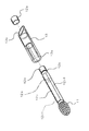
次に、添付図面を参照して本発明に係る骨接合具の実施形態について説明する。図1及び図2は本実施形態の骨接合具を用いた骨接合装置の全体構造を示す部分断面図であり、図3は本実施形態のスリーブとラグスクリューとからなる骨接合具の組立構造を示す分解斜視図である。 Next, an embodiment of a bone fastener according to the present invention will be described with reference to the accompanying drawings. 1 and 2 are partial cross-sectional views showing the overall structure of an osteosynthesis device using the osteosynthesis device of this embodiment, and FIG. 3 is an assembly structure of the osteosynthesis device comprising a sleeve and a lag screw of this embodiment. FIG.
本実施形態は、末端に設けられたスクリュー部11及びこのスクリュー部11より基端側に設けられた軸部12を備えたラグスクリュー10と、このラグスクリュー10の軸部12を収容するスリーブ13及びこのスリーブ13を接続するように構成されたプレート14からなる取付体とを有している。
In the present embodiment, a
ラグスクリュー10は、大腿骨の外側面から大腿骨頭部へ向けて斜め上方にねじ込まれるものである。その中心にはガイドピン(ガイドワイヤ)を挿通するための軸孔が設けられている。
The
ラグスクリュー10のスクリュー部11は骨内においてタッピングを行いながら骨にしっかりと結合するように構成されている。ラグスクリュー10の軸部12は、他の部分よりもやや拡径された頭部12aと、この頭部12aの末端側に隣接して形成されたやや縮径された円筒外面部12bと、この円筒外面部12bの末端側に隣接して形成された異形外面部12cとを備えている。この異形外面部12cは、図3に示すように、円筒面の相互に対向する部分に一対の平坦面12c1を形成してなる外面形状を有するものであり、その断面形状は図中において12sとして示してある。
The
一方、スリーブ13は全体として円筒形状に形成され、やや縮径した内縁を有する先端部13aと、プレート14の外面と適合するように斜めに形成された後端部13bとを備えている。先端部13aの内縁は全周にわたり内側へ突出して係止部を構成する。すなわち、上記ラグスクリュー10の異形外面部12cに対し、回転方向に係合し得る内縁形状、すなわち円形の対向する一対の部分がほぼ平坦に形成されてなる開口形状、に形成されている。
On the other hand, the
プレート14は、その一端側に上記スリーブ13の後端部13bを収容する傾斜した取付孔14aを備えているとともに、プレート14を大腿骨の外側表面上に固定するための、図示しない骨ネジを挿通して係合させるように構成された複数の固定孔14bを備えている。ここで、図示のようにスリーブ13の外面に形成された横溝13cに対して係合するリブ14cを出没自在に構成するなどの方法で、スリーブ13とプレート14とを着脱自在に構成してもよく(例えば、リブをバヨネット構造で出没自在に構成するなど、特公平5−81254号公報や実用新案登録第2504411号公報に記載されている構造を採用してもよく)、或いは、スリーブ13とプレート14とが溶接等によって固着されているなど、一体に構成されていてもよい。
The
図3に示すように、ラグスクリュー10の基端部12dは、スリーブ13の先端部13aを通過できる外径に形成され、この軸部12をスリーブ13内に挿通させた後、基端部12dに円筒状の環状部材12eを溶着、接着等によって固着させることにより、上記頭部12aが形成される。この頭部12aは先端部13aを通過できないように構成されているので、ラグスクリュー10とスリーブ13とは相互に抜け止めされた状態になる。
As shown in FIG. 3, the
なお、図1及び図2に示すように、ラグスクリュー10の基端部12dには、上記軸孔に連通する基端側孔部が設けられ、この基端側孔部の浅い部分は回転工具(図示せず)を係合させるための角穴12fとなり、また、その穴の深い部分には雌ネジ部12gが形成される。この雌ネジ部12gに螺合する雄ネジ部を有する牽引器具(図示せず)によって、大腿骨頭部の骨折部を整復するためにラグスクリュー10を牽引することができる。
As shown in FIGS. 1 and 2, the
図4(a)には、スリーブ13の先端部13aと、上記異形外面部12cとの係合状態を示す。図示点線で示す円筒外面部12bは先端部13aの内部で回転自在に構成されているが、異形外面部12cは先端部13a内において回転方向に固定されるように構成されている。
FIG. 4A shows an engaged state between the
図4(b)に示すものは上記実施形態とは異なる実施形態におけるスリーブの先端部23aとラグスクリューの異形外面部22cとの係合状態を示すものである。この先端部23aの内縁は角孔形状(図示例では6角孔)に形成され、異形外面部22cの外面は、その角孔形状に対応した角形状(図示例では6角形)に形成されている。この場合の円筒外面部22bの外面は、異形外面部22cの角形状の内接円とほぼ等しい断面形状を備えている。
FIG. 4B shows an engagement state between the sleeve distal end portion 23a and the lag screw deformed
図4(c)に示すものは上記実施形態とは異なる別の実施形態におけるスリーブの先端部33aとラグスクリューの異形外面部32cとの係合状態を示すものである。この先端部33aの内縁には回転方向に複数の曲面状の凸部若しくは凹部が形成され、異形外面部32cの外面は、その凸部若しくは凹部に対応する凹溝若しくは凸リブを有する形状に形成されている。この場合の円筒外面部32bもまた、異形外面部32cの断面の内接円形状とほぼ等しい断面形状を備えている。
FIG. 4C shows an engagement state between the distal end portion 33a of the sleeve and the deformed
次に、本実施形態の骨接合装置を用いて大腿骨の頭部近傍の骨折を修復する方法について説明する。例えば、大腿骨の頸部骨折においては、まず、大腿骨の外側表面からガイドピンを挿入し、大腿骨の頭部内にガイドピンの先端部が到達するようにセットする。次に、このガイドピンに沿ってリーマ等の穿孔器具を導入し、大腿骨の外側表面から大腿骨の頭部内に向けて穿孔する。このとき、取付体のスリーブを収容できるようにするために、穿孔された穴のうち外側表面に近い浅い部分を、深い部分よりもやや大きな内径を有するように形成する。 Next, a method for repairing a fracture near the head of the femur using the osteosynthesis device of the present embodiment will be described. For example, in the case of a femoral neck fracture, first, a guide pin is inserted from the outer surface of the femur and is set so that the tip of the guide pin reaches the head of the femur. Next, a piercing device such as a reamer is introduced along the guide pin, and piercing is performed from the outer surface of the femur into the head of the femur. At this time, in order to accommodate the sleeve of the attachment body, a shallow portion near the outer surface of the drilled hole is formed to have a slightly larger inner diameter than the deep portion.
次に、ガイドピンに沿ってラグスクリュー10を大腿骨にねじ込む。ここで、ラグスクリュー10は上述のように取付体に接続された状態になっているが、ラグスクリュー10をスリーブ13から最も突出させた図1に示す状態とすることにより、軸部12の円筒外面部12bがスリーブ13の先端部13aの内側に配置され、その結果、ラグスクリュー10をスリーブ13に対して回転自在にすることができる。そして、この状態でラグスクリュー10の頭部12aの端面に穿設された角穴12fにドライバー工具の先端を挿入して回転させ、ラグスクリュー10を骨内にねじ込んでいく。
Next, the
ラグスクリュー10のスクリュー部11が大腿骨頭部の内部に導入され、充分な深さまで達すると、プレート14を大腿骨の外側表面に押し付けるようにして、スリーブ13を大腿骨の外側表面に穿設された穴内に押し込む。この状態を図2に示す。この状態では、スリーブ13の先端部13aがラグスクリュー10の軸部12のうちの異形外面部12cに係合した状態となり、スリーブ13に対してラグスクリュー10が回転方向に規制される。
When the
最後に、プレート14の固定孔14bを通して大腿骨の外側表面から図示しない骨ネジをねじ込み、プレート14を大腿骨の外側表面上に固定する。
Finally, a bone screw (not shown) is screwed from the outer surface of the femur through the fixing
以上説明したように、本実施形態では、スリーブ13の先端部13aとラグスクリュー10の円筒外面部12bとが対向する状態でラグスクリュー10を回転させて骨内にねじ込み、ねじ込みが完了した後にスリーブ13を押し込むことにより、その先端部13aがラグスクリュー10の異形外面部12cに対して回転方向に係合するように構成することができ、この状態でプレート14を骨の表面上に固定できる。したがって、骨への取付けが完了した状態でラグスクリュー10がプレート14に対して回転しないように規制することができる。したがって、手術後にラグスクリュー10とともにスクリュー部11に固定された骨折部分が回旋し、骨折部の損傷を引き起こすという事態の発生を回避することができる。
As described above, in the present embodiment, the
また、ラグスクリュー10を骨内にねじ込んだ状態で、軸部12の異形外面部12cとスリーブ13の先端部13aとの回転方向の姿勢が整合しない場合、そのままスリーブ13及びプレート14を外側に引き出し、円筒外面部12bがスリーブ13の先端部13aに対向した状態としてラグスクリュー10の回転姿勢を微調整し、再びスリーブ13及びプレート14を押し込んでスリーブ13の先端部13aを異形外面部12cに係合させるようにすることができるので、熟練者でなくても手間をかけずに容易に手術を行うことができる。
Further, in the state where the
なお、上記スリーブの先端部13aは、ラグスクリューの第2外面部に相当する円筒外面部12bと、第1外面部に相当する異形外面部12cとにそれぞれ作用する上記の係合部に相当するものであるが、この係合部はスリーブの先端部である必要はなく、先端部以外の適宜の部位に設けることが可能である。
The
図5は、上記実施形態とは異なる別の実施形態の構造を示すものである。この実施形態において、プレート14は上記の実施形態と同様であり、その説明は省略する。
FIG. 5 shows the structure of another embodiment different from the above embodiment. In this embodiment, the
この実施形態では、ラグスクリュー40は、上記と同様にスクリュー部41及び軸部42を有する。このラグスクリュー40において、軸部42の基端には角形状(図示例では6角形状)の頭部42aが設けられ、この頭部42a以外の軸部は頭部42aの内接円以下の外径を有する円筒状部42bとなっている。
In this embodiment, the
また、スリーブ43は、ラグスクリュー40の円筒状部42bが挿通することはできるが、頭部42aが脱出しないように抜け止めする先端部43aと、この先端部43aよりも後端部43b寄りに形成され、ラグスクリュー40の頭部42aの外接円以上の内径を有する円筒内面部43dと、この円筒内面部43dよりも後端部43b寄りに形成され、ラグスクリュー40の頭部42aに対して回転方向に係合し得る角形状(図示例では6角孔状)の異形内面部43eとを備えている。
The
この実施形態において、ラグスクリュー40がスリーブ43から突出した状態(図5に示す状態)では、ラグスクリュー40の頭部42aがスリーブ43の円筒内面部43d内に配置されているので、ラグスクリュー40はスリーブ43及びプレートに対して自在に回転することができる。また、ラグスクリュー40が図5に示す状態よりもスリーブ43の内部に引き込まれた状態では、ラグスクリュー40の頭部42aが異形内面部43e内に配置され、相互に回転方向に係合する。したがって、ラグスクリュー40はスリーブ43及びプレートに対して回転方向に固定(規制)された状態となる。
In this embodiment, when the
この実施形態においても、上記の図1乃至図3に示す実施形態と同様の作用効果を奏する。なお、上記の頭部42aの外面形状と異形内面部43eとは、上記実施形態と同様に(図4に示すように)、種々の回転規制態様を採ることができる。また、上記頭部42aはスリーブの第2内面部に相当する円筒内面部43d及び第1内面部に相当する異形内面部43eにそれぞれ作用する上記の被係合部に相当するものであるが、この被係合部はラグスクリューの頭部である必要はなく、頭部以外の適宜の部位に設けることができる。
Also in this embodiment, the same operational effects as in the embodiment shown in FIGS. The outer surface shape of the head portion 42a and the deformed
10,40 ラグスクリュー
11,41 スクリュー部
12,42 軸部
12a,42a 頭部
12b 円筒外面部
12c 異形外面部
13,43 スリーブ
13a,43a 先端部
14 プレート
43d 円筒内面部
43e 異形内面部
10, 40
Claims (2)
前記軸部には、前記スリーブに設けられた係合部に対して回転方向に規制されるように構成された第1外面部と、前記係合部に対して回転可能に構成された第2外面部とが軸線方向の異なる部位に設けられ、
前記第1外面部は前記第2外面部より前記ラグスクリューの末端側に設けられ、
前記ラグスクリューの基端部には前記ラグスクリューを回転させるための回転工具を係合させる基端側孔部が設けられ、
前記軸部が前記スリーブから最も引き出され前記頭部が前記スリーブの先端部に当接したときに前記係合部の内側に前記第2外面部が配置されて前記ラグスクリューが前記スリーブに対して回転可能になり、前記軸部が前記スリーブ内に引き込まれて前記頭部が前記スリーブの先端部から離間するとともに前記係合部の内側に前記第1外面部が配置されたときに前記ラグスクリューが前記スリーブに対して回転方向に規制されるように構成されていることを特徴とする骨接合具。 A lag screw having a screw portion and a shaft portion provided on a proximal end side of the screw portion; and a sleeve for housing the shaft portion of the lag screw, wherein the lag screw slides on the sleeve. The head portion formed at the base end portion of the lag screw is configured so as not to pass through the tip end portion of the sleeve, and the lag screw and the sleeve are prevented from being detached from each other. An osteosynthesis tool,
The shaft portion includes a first outer surface portion configured to be regulated in a rotational direction with respect to an engaging portion provided on the sleeve, and a second outer surface configured to be rotatable with respect to the engaging portion. The outer surface portion is provided at a different part in the axial direction,
The first outer surface portion is provided on the terminal side of the lag screw from the second outer surface portion,
The base end of the lag screw is provided with a base end side hole for engaging a rotary tool for rotating the lag screw,
The second outer surface portion is disposed inside the engagement portion when the shaft portion is pulled out most from the sleeve and the head portion comes into contact with the distal end portion of the sleeve, and the lag screw is positioned relative to the sleeve. The lag screw becomes rotatable when the shaft portion is drawn into the sleeve, the head is separated from the distal end portion of the sleeve, and the first outer surface portion is disposed inside the engagement portion. Is configured to be restricted in a rotational direction with respect to the sleeve.
前記スリーブには、前記軸部に設けられた被係合部に対して回転止めされるように構成された第1内面部と、前記被係合部に対して回転可能に構成された第2内面部とが軸線方向の異なる部位に設けられ、
前記第1内面部は前記第2内面部より前記スリーブの後端側に設けられ、
前記ラグスクリューの基端部には前記ラグスクリューを回転させるための回転工具を係合させる基端側孔部が設けられ、
前記軸部が前記スリーブから最も引き出され前記頭部が前記スリーブの先端部に当接したときに前記被係合部が前記第2内面部の内側に配置されて前記ラグスクリューが前記スリーブに対して回転可能になり、前記軸部が前記スリーブ内に引き込まれて前記頭部が前記スリーブの先端部から離間するとともに前記被係合部が前記第1内面部の内側に配置されたときに前記ラグスクリューが前記スリーブに対して回転方向に規制されるように構成されていることを特徴とする骨接合具。 A lag screw having a screw portion and a shaft portion provided on a proximal end side of the screw portion; and a sleeve for housing the shaft portion of the lag screw, wherein the lag screw slides on the sleeve. The head portion formed at the base end portion of the lag screw is configured so as not to pass through the tip end portion of the sleeve, and the lag screw and the sleeve are prevented from being detached from each other. An osteosynthesis tool,
The sleeve includes a first inner surface portion configured to be rotationally stopped with respect to an engaged portion provided on the shaft portion, and a second configured to be rotatable with respect to the engaged portion. The inner surface part is provided at a different part in the axial direction,
The first inner surface is provided on the rear end side of the sleeve from the second inner surface,
The base end of the lag screw is provided with a base end side hole for engaging a rotary tool for rotating the lag screw,
When the shaft portion is pulled out most from the sleeve and the head comes into contact with the tip of the sleeve, the engaged portion is disposed inside the second inner surface portion , and the lag screw is placed against the sleeve. The shaft portion is drawn into the sleeve, the head portion is separated from the tip portion of the sleeve, and the engaged portion is disposed inside the first inner surface portion. An osteosynthesis device characterized in that a lag screw is configured to be regulated in a rotational direction with respect to the sleeve.
Priority Applications (1)
| Application Number | Priority Date | Filing Date | Title |
|---|---|---|---|
| JP2007185849A JP4625051B2 (en) | 2007-07-17 | 2007-07-17 | Osteosynthesis |
Applications Claiming Priority (1)
| Application Number | Priority Date | Filing Date | Title |
|---|---|---|---|
| JP2007185849A JP4625051B2 (en) | 2007-07-17 | 2007-07-17 | Osteosynthesis |
Related Parent Applications (1)
| Application Number | Title | Priority Date | Filing Date |
|---|---|---|---|
| JP2000266635A Division JP4018327B2 (en) | 2000-09-04 | 2000-09-04 | Osteosynthesis device |
Publications (3)
| Publication Number | Publication Date |
|---|---|
| JP2007260446A JP2007260446A (en) | 2007-10-11 |
| JP2007260446A5 JP2007260446A5 (en) | 2007-11-22 |
| JP4625051B2 true JP4625051B2 (en) | 2011-02-02 |
Family
ID=38633974
Family Applications (1)
| Application Number | Title | Priority Date | Filing Date |
|---|---|---|---|
| JP2007185849A Expired - Fee Related JP4625051B2 (en) | 2007-07-17 | 2007-07-17 | Osteosynthesis |
Country Status (1)
| Country | Link |
|---|---|
| JP (1) | JP4625051B2 (en) |
Families Citing this family (1)
| Publication number | Priority date | Publication date | Assignee | Title |
|---|---|---|---|---|
| US9662156B2 (en) * | 2011-11-18 | 2017-05-30 | DePuy Synthes Products, Inc. | Femoral neck fracture implant |
Citations (4)
| Publication number | Priority date | Publication date | Assignee | Title |
|---|---|---|---|---|
| JPH0321149U (en) * | 1989-06-02 | 1991-03-01 | ||
| JPH0898846A (en) * | 1994-09-30 | 1996-04-16 | Homuzu Giken:Kk | Connector for femur |
| JPH09108237A (en) * | 1995-08-23 | 1997-04-28 | Biomat | Implant for upper femur end bone joining operation |
| JPH11137566A (en) * | 1997-11-12 | 1999-05-25 | Mizuho Ika Kogyo Kk | Intramedullary nail |
-
2007
- 2007-07-17 JP JP2007185849A patent/JP4625051B2/en not_active Expired - Fee Related
Patent Citations (4)
| Publication number | Priority date | Publication date | Assignee | Title |
|---|---|---|---|---|
| JPH0321149U (en) * | 1989-06-02 | 1991-03-01 | ||
| JPH0898846A (en) * | 1994-09-30 | 1996-04-16 | Homuzu Giken:Kk | Connector for femur |
| JPH09108237A (en) * | 1995-08-23 | 1997-04-28 | Biomat | Implant for upper femur end bone joining operation |
| JPH11137566A (en) * | 1997-11-12 | 1999-05-25 | Mizuho Ika Kogyo Kk | Intramedullary nail |
Also Published As
| Publication number | Publication date |
|---|---|
| JP2007260446A (en) | 2007-10-11 |
Similar Documents
| Publication | Publication Date | Title |
|---|---|---|
| JP6677704B2 (en) | Self-holding screw head | |
| JP6301247B2 (en) | System and method for joints of dental implants and abutments for restoration | |
| US9387025B2 (en) | Bone screw and self-retaining driver | |
| JP4728322B2 (en) | Adjustable tool for fasteners cannulated | |
| US11325231B2 (en) | Self-retaining screwdriver with engaging tip feature | |
| JP4018327B2 (en) | Osteosynthesis device | |
| US8814880B2 (en) | Device and method for mounting an object on a bone | |
| CA2647888C (en) | System for insertion of implants | |
| US20070043379A1 (en) | Bone screw/driver assembly and method | |
| JP2007532191A5 (en) | ||
| US20080147128A1 (en) | Cannulated bone screw and cannulated driver for the implantation thereof | |
| JP2007530149A (en) | Driver for extraction | |
| US20110270322A1 (en) | Surgical fastener and associated systems and methods | |
| KR20080106320A (en) | Locking bone plate with controlled locking screw misalignment | |
| KR101672159B1 (en) | Osteosynthesis device for proximal femur fracture and master screw type screw device for osteosynthesis device for proximal femur fracture | |
| JP4625051B2 (en) | Osteosynthesis | |
| JP2007260446A5 (en) | ||
| WO2016174787A1 (en) | Bone connector | |
| CN108720906A (en) | Medical tunneler | |
| CA2639899A1 (en) | Handle connector for hand tool or utensil | |
| JP3979915B2 (en) | Osteosynthesis device | |
| CN211704796U (en) | Intramedullary nail and intramedullary nail internal fixation kit | |
| JP5162722B1 (en) | Medical nut | |
| JP2005007513A (en) | Deep hole cutting tool | |
| KR101952087B1 (en) | Fixture and aburtment fasteners |
Legal Events
| Date | Code | Title | Description |
|---|---|---|---|
| A521 | Written amendment |
Free format text: JAPANESE INTERMEDIATE CODE: A523 Effective date: 20070904 |
|
| A621 | Written request for application examination |
Free format text: JAPANESE INTERMEDIATE CODE: A621 Effective date: 20070904 |
|
| A131 | Notification of reasons for refusal |
Free format text: JAPANESE INTERMEDIATE CODE: A131 Effective date: 20100714 |
|
| A977 | Report on retrieval |
Free format text: JAPANESE INTERMEDIATE CODE: A971007 Effective date: 20100715 |
|
| A521 | Written amendment |
Free format text: JAPANESE INTERMEDIATE CODE: A523 Effective date: 20100913 |
|
| TRDD | Decision of grant or rejection written | ||
| A01 | Written decision to grant a patent or to grant a registration (utility model) |
Free format text: JAPANESE INTERMEDIATE CODE: A01 Effective date: 20101005 |
|
| A01 | Written decision to grant a patent or to grant a registration (utility model) |
Free format text: JAPANESE INTERMEDIATE CODE: A01 |
|
| A61 | First payment of annual fees (during grant procedure) |
Free format text: JAPANESE INTERMEDIATE CODE: A61 Effective date: 20101104 |
|
| R150 | Certificate of patent or registration of utility model |
Ref document number: 4625051 Country of ref document: JP Free format text: JAPANESE INTERMEDIATE CODE: R150 Free format text: JAPANESE INTERMEDIATE CODE: R150 |
|
| FPAY | Renewal fee payment (event date is renewal date of database) |
Free format text: PAYMENT UNTIL: 20131112 Year of fee payment: 3 |
|
| R250 | Receipt of annual fees |
Free format text: JAPANESE INTERMEDIATE CODE: R250 |
|
| R250 | Receipt of annual fees |
Free format text: JAPANESE INTERMEDIATE CODE: R250 |
|
| R250 | Receipt of annual fees |
Free format text: JAPANESE INTERMEDIATE CODE: R250 |
|
| R250 | Receipt of annual fees |
Free format text: JAPANESE INTERMEDIATE CODE: R250 |
|
| R250 | Receipt of annual fees |
Free format text: JAPANESE INTERMEDIATE CODE: R250 |
|
| R250 | Receipt of annual fees |
Free format text: JAPANESE INTERMEDIATE CODE: R250 |
|
| LAPS | Cancellation because of no payment of annual fees |