JP4622872B2 - VEHICLE POWER DEVICE, VEHICLE, AND CONTROL METHOD FOR VEHICLE POWER DEVICE - Google Patents
VEHICLE POWER DEVICE, VEHICLE, AND CONTROL METHOD FOR VEHICLE POWER DEVICE Download PDFInfo
- Publication number
- JP4622872B2 JP4622872B2 JP2006018055A JP2006018055A JP4622872B2 JP 4622872 B2 JP4622872 B2 JP 4622872B2 JP 2006018055 A JP2006018055 A JP 2006018055A JP 2006018055 A JP2006018055 A JP 2006018055A JP 4622872 B2 JP4622872 B2 JP 4622872B2
- Authority
- JP
- Japan
- Prior art keywords
- voltage
- rotating electrical
- vehicle
- operation state
- power supply
- Prior art date
- Legal status (The legal status is an assumption and is not a legal conclusion. Google has not performed a legal analysis and makes no representation as to the accuracy of the status listed.)
- Active
Links
Images


Classifications
-
- B—PERFORMING OPERATIONS; TRANSPORTING
- B60—VEHICLES IN GENERAL
- B60L—PROPULSION OF ELECTRICALLY-PROPELLED VEHICLES; SUPPLYING ELECTRIC POWER FOR AUXILIARY EQUIPMENT OF ELECTRICALLY-PROPELLED VEHICLES; ELECTRODYNAMIC BRAKE SYSTEMS FOR VEHICLES IN GENERAL; MAGNETIC SUSPENSION OR LEVITATION FOR VEHICLES; MONITORING OPERATING VARIABLES OF ELECTRICALLY-PROPELLED VEHICLES; ELECTRIC SAFETY DEVICES FOR ELECTRICALLY-PROPELLED VEHICLES
- B60L15/00—Methods, circuits, or devices for controlling the traction-motor speed of electrically-propelled vehicles
- B60L15/007—Physical arrangements or structures of drive train converters specially adapted for the propulsion motors of electric vehicles
-
- B—PERFORMING OPERATIONS; TRANSPORTING
- B60—VEHICLES IN GENERAL
- B60L—PROPULSION OF ELECTRICALLY-PROPELLED VEHICLES; SUPPLYING ELECTRIC POWER FOR AUXILIARY EQUIPMENT OF ELECTRICALLY-PROPELLED VEHICLES; ELECTRODYNAMIC BRAKE SYSTEMS FOR VEHICLES IN GENERAL; MAGNETIC SUSPENSION OR LEVITATION FOR VEHICLES; MONITORING OPERATING VARIABLES OF ELECTRICALLY-PROPELLED VEHICLES; ELECTRIC SAFETY DEVICES FOR ELECTRICALLY-PROPELLED VEHICLES
- B60L50/00—Electric propulsion with power supplied within the vehicle
- B60L50/10—Electric propulsion with power supplied within the vehicle using propulsion power supplied by engine-driven generators, e.g. generators driven by combustion engines
- B60L50/16—Electric propulsion with power supplied within the vehicle using propulsion power supplied by engine-driven generators, e.g. generators driven by combustion engines with provision for separate direct mechanical propulsion
-
- B—PERFORMING OPERATIONS; TRANSPORTING
- B60—VEHICLES IN GENERAL
- B60L—PROPULSION OF ELECTRICALLY-PROPELLED VEHICLES; SUPPLYING ELECTRIC POWER FOR AUXILIARY EQUIPMENT OF ELECTRICALLY-PROPELLED VEHICLES; ELECTRODYNAMIC BRAKE SYSTEMS FOR VEHICLES IN GENERAL; MAGNETIC SUSPENSION OR LEVITATION FOR VEHICLES; MONITORING OPERATING VARIABLES OF ELECTRICALLY-PROPELLED VEHICLES; ELECTRIC SAFETY DEVICES FOR ELECTRICALLY-PROPELLED VEHICLES
- B60L50/00—Electric propulsion with power supplied within the vehicle
- B60L50/50—Electric propulsion with power supplied within the vehicle using propulsion power supplied by batteries or fuel cells
- B60L50/60—Electric propulsion with power supplied within the vehicle using propulsion power supplied by batteries or fuel cells using power supplied by batteries
- B60L50/61—Electric propulsion with power supplied within the vehicle using propulsion power supplied by batteries or fuel cells using power supplied by batteries by batteries charged by engine-driven generators, e.g. series hybrid electric vehicles
-
- H—ELECTRICITY
- H02—GENERATION; CONVERSION OR DISTRIBUTION OF ELECTRIC POWER
- H02P—CONTROL OR REGULATION OF ELECTRIC MOTORS, ELECTRIC GENERATORS OR DYNAMO-ELECTRIC CONVERTERS; CONTROLLING TRANSFORMERS, REACTORS OR CHOKE COILS
- H02P27/00—Arrangements or methods for the control of AC motors characterised by the kind of supply voltage
- H02P27/04—Arrangements or methods for the control of AC motors characterised by the kind of supply voltage using variable-frequency supply voltage, e.g. inverter or converter supply voltage
- H02P27/06—Arrangements or methods for the control of AC motors characterised by the kind of supply voltage using variable-frequency supply voltage, e.g. inverter or converter supply voltage using dc to ac converters or inverters
- H02P27/08—Arrangements or methods for the control of AC motors characterised by the kind of supply voltage using variable-frequency supply voltage, e.g. inverter or converter supply voltage using dc to ac converters or inverters with pulse width modulation
-
- H—ELECTRICITY
- H02—GENERATION; CONVERSION OR DISTRIBUTION OF ELECTRIC POWER
- H02P—CONTROL OR REGULATION OF ELECTRIC MOTORS, ELECTRIC GENERATORS OR DYNAMO-ELECTRIC CONVERTERS; CONTROLLING TRANSFORMERS, REACTORS OR CHOKE COILS
- H02P5/00—Arrangements specially adapted for regulating or controlling the speed or torque of two or more electric motors
- H02P5/74—Arrangements specially adapted for regulating or controlling the speed or torque of two or more electric motors controlling two or more ac dynamo-electric motors
-
- B—PERFORMING OPERATIONS; TRANSPORTING
- B60—VEHICLES IN GENERAL
- B60L—PROPULSION OF ELECTRICALLY-PROPELLED VEHICLES; SUPPLYING ELECTRIC POWER FOR AUXILIARY EQUIPMENT OF ELECTRICALLY-PROPELLED VEHICLES; ELECTRODYNAMIC BRAKE SYSTEMS FOR VEHICLES IN GENERAL; MAGNETIC SUSPENSION OR LEVITATION FOR VEHICLES; MONITORING OPERATING VARIABLES OF ELECTRICALLY-PROPELLED VEHICLES; ELECTRIC SAFETY DEVICES FOR ELECTRICALLY-PROPELLED VEHICLES
- B60L2210/00—Converter types
- B60L2210/10—DC to DC converters
- B60L2210/14—Boost converters
-
- B—PERFORMING OPERATIONS; TRANSPORTING
- B60—VEHICLES IN GENERAL
- B60L—PROPULSION OF ELECTRICALLY-PROPELLED VEHICLES; SUPPLYING ELECTRIC POWER FOR AUXILIARY EQUIPMENT OF ELECTRICALLY-PROPELLED VEHICLES; ELECTRODYNAMIC BRAKE SYSTEMS FOR VEHICLES IN GENERAL; MAGNETIC SUSPENSION OR LEVITATION FOR VEHICLES; MONITORING OPERATING VARIABLES OF ELECTRICALLY-PROPELLED VEHICLES; ELECTRIC SAFETY DEVICES FOR ELECTRICALLY-PROPELLED VEHICLES
- B60L2240/00—Control parameters of input or output; Target parameters
- B60L2240/40—Drive Train control parameters
- B60L2240/42—Drive Train control parameters related to electric machines
- B60L2240/421—Speed
-
- B—PERFORMING OPERATIONS; TRANSPORTING
- B60—VEHICLES IN GENERAL
- B60L—PROPULSION OF ELECTRICALLY-PROPELLED VEHICLES; SUPPLYING ELECTRIC POWER FOR AUXILIARY EQUIPMENT OF ELECTRICALLY-PROPELLED VEHICLES; ELECTRODYNAMIC BRAKE SYSTEMS FOR VEHICLES IN GENERAL; MAGNETIC SUSPENSION OR LEVITATION FOR VEHICLES; MONITORING OPERATING VARIABLES OF ELECTRICALLY-PROPELLED VEHICLES; ELECTRIC SAFETY DEVICES FOR ELECTRICALLY-PROPELLED VEHICLES
- B60L2250/00—Driver interactions
- B60L2250/30—Driver interactions by voice
-
- B—PERFORMING OPERATIONS; TRANSPORTING
- B60—VEHICLES IN GENERAL
- B60Y—INDEXING SCHEME RELATING TO ASPECTS CROSS-CUTTING VEHICLE TECHNOLOGY
- B60Y2200/00—Type of vehicle
- B60Y2200/90—Vehicles comprising electric prime movers
- B60Y2200/91—Electric vehicles
-
- B—PERFORMING OPERATIONS; TRANSPORTING
- B60—VEHICLES IN GENERAL
- B60Y—INDEXING SCHEME RELATING TO ASPECTS CROSS-CUTTING VEHICLE TECHNOLOGY
- B60Y2200/00—Type of vehicle
- B60Y2200/90—Vehicles comprising electric prime movers
- B60Y2200/92—Hybrid vehicles
-
- B—PERFORMING OPERATIONS; TRANSPORTING
- B60—VEHICLES IN GENERAL
- B60Y—INDEXING SCHEME RELATING TO ASPECTS CROSS-CUTTING VEHICLE TECHNOLOGY
- B60Y2400/00—Special features of vehicle units
- B60Y2400/30—Sensors
- B60Y2400/308—Electric sensors
- B60Y2400/3084—Electric currents sensors
-
- H—ELECTRICITY
- H02—GENERATION; CONVERSION OR DISTRIBUTION OF ELECTRIC POWER
- H02P—CONTROL OR REGULATION OF ELECTRIC MOTORS, ELECTRIC GENERATORS OR DYNAMO-ELECTRIC CONVERTERS; CONTROLLING TRANSFORMERS, REACTORS OR CHOKE COILS
- H02P2201/00—Indexing scheme relating to controlling arrangements characterised by the converter used
- H02P2201/09—Boost converter, i.e. DC-DC step up converter increasing the voltage between the supply and the inverter driving the motor
-
- Y—GENERAL TAGGING OF NEW TECHNOLOGICAL DEVELOPMENTS; GENERAL TAGGING OF CROSS-SECTIONAL TECHNOLOGIES SPANNING OVER SEVERAL SECTIONS OF THE IPC; TECHNICAL SUBJECTS COVERED BY FORMER USPC CROSS-REFERENCE ART COLLECTIONS [XRACs] AND DIGESTS
- Y02—TECHNOLOGIES OR APPLICATIONS FOR MITIGATION OR ADAPTATION AGAINST CLIMATE CHANGE
- Y02T—CLIMATE CHANGE MITIGATION TECHNOLOGIES RELATED TO TRANSPORTATION
- Y02T10/00—Road transport of goods or passengers
- Y02T10/60—Other road transportation technologies with climate change mitigation effect
- Y02T10/62—Hybrid vehicles
-
- Y—GENERAL TAGGING OF NEW TECHNOLOGICAL DEVELOPMENTS; GENERAL TAGGING OF CROSS-SECTIONAL TECHNOLOGIES SPANNING OVER SEVERAL SECTIONS OF THE IPC; TECHNICAL SUBJECTS COVERED BY FORMER USPC CROSS-REFERENCE ART COLLECTIONS [XRACs] AND DIGESTS
- Y02—TECHNOLOGIES OR APPLICATIONS FOR MITIGATION OR ADAPTATION AGAINST CLIMATE CHANGE
- Y02T—CLIMATE CHANGE MITIGATION TECHNOLOGIES RELATED TO TRANSPORTATION
- Y02T10/00—Road transport of goods or passengers
- Y02T10/60—Other road transportation technologies with climate change mitigation effect
- Y02T10/64—Electric machine technologies in electromobility
-
- Y—GENERAL TAGGING OF NEW TECHNOLOGICAL DEVELOPMENTS; GENERAL TAGGING OF CROSS-SECTIONAL TECHNOLOGIES SPANNING OVER SEVERAL SECTIONS OF THE IPC; TECHNICAL SUBJECTS COVERED BY FORMER USPC CROSS-REFERENCE ART COLLECTIONS [XRACs] AND DIGESTS
- Y02—TECHNOLOGIES OR APPLICATIONS FOR MITIGATION OR ADAPTATION AGAINST CLIMATE CHANGE
- Y02T—CLIMATE CHANGE MITIGATION TECHNOLOGIES RELATED TO TRANSPORTATION
- Y02T10/00—Road transport of goods or passengers
- Y02T10/60—Other road transportation technologies with climate change mitigation effect
- Y02T10/70—Energy storage systems for electromobility, e.g. batteries
-
- Y—GENERAL TAGGING OF NEW TECHNOLOGICAL DEVELOPMENTS; GENERAL TAGGING OF CROSS-SECTIONAL TECHNOLOGIES SPANNING OVER SEVERAL SECTIONS OF THE IPC; TECHNICAL SUBJECTS COVERED BY FORMER USPC CROSS-REFERENCE ART COLLECTIONS [XRACs] AND DIGESTS
- Y02—TECHNOLOGIES OR APPLICATIONS FOR MITIGATION OR ADAPTATION AGAINST CLIMATE CHANGE
- Y02T—CLIMATE CHANGE MITIGATION TECHNOLOGIES RELATED TO TRANSPORTATION
- Y02T10/00—Road transport of goods or passengers
- Y02T10/60—Other road transportation technologies with climate change mitigation effect
- Y02T10/7072—Electromobility specific charging systems or methods for batteries, ultracapacitors, supercapacitors or double-layer capacitors
-
- Y—GENERAL TAGGING OF NEW TECHNOLOGICAL DEVELOPMENTS; GENERAL TAGGING OF CROSS-SECTIONAL TECHNOLOGIES SPANNING OVER SEVERAL SECTIONS OF THE IPC; TECHNICAL SUBJECTS COVERED BY FORMER USPC CROSS-REFERENCE ART COLLECTIONS [XRACs] AND DIGESTS
- Y02—TECHNOLOGIES OR APPLICATIONS FOR MITIGATION OR ADAPTATION AGAINST CLIMATE CHANGE
- Y02T—CLIMATE CHANGE MITIGATION TECHNOLOGIES RELATED TO TRANSPORTATION
- Y02T10/00—Road transport of goods or passengers
- Y02T10/60—Other road transportation technologies with climate change mitigation effect
- Y02T10/72—Electric energy management in electromobility
-
- Y—GENERAL TAGGING OF NEW TECHNOLOGICAL DEVELOPMENTS; GENERAL TAGGING OF CROSS-SECTIONAL TECHNOLOGIES SPANNING OVER SEVERAL SECTIONS OF THE IPC; TECHNICAL SUBJECTS COVERED BY FORMER USPC CROSS-REFERENCE ART COLLECTIONS [XRACs] AND DIGESTS
- Y10—TECHNICAL SUBJECTS COVERED BY FORMER USPC
- Y10S—TECHNICAL SUBJECTS COVERED BY FORMER USPC CROSS-REFERENCE ART COLLECTIONS [XRACs] AND DIGESTS
- Y10S903/00—Hybrid electric vehicles, HEVS
- Y10S903/902—Prime movers comprising electrical and internal combustion motors
- Y10S903/903—Prime movers comprising electrical and internal combustion motors having energy storing means, e.g. battery, capacitor
- Y10S903/904—Component specially adapted for hev
Description
この発明は、車両の電源装置および車両に関し、特に蓄電装置の電源電圧を昇圧して供給する車両の電源装置および車両に関する。 The present invention relates to a vehicle power supply device and a vehicle, and more particularly to a vehicle power supply device and a vehicle that boost and supply a power supply voltage of a power storage device.
近年、電気自動車、ハイブリッド自動車および燃料電池自動車などが環境にやさしい車両として大いに注目を浴びている。 In recent years, electric vehicles, hybrid vehicles, fuel cell vehicles, and the like have received much attention as environmentally friendly vehicles.
このような車両は、従来よりも100Vを超える高圧のバッテリなどの蓄電装置を搭載し、この蓄電装置の電力を用いてモータを回転させて車両を駆動する。 Such a vehicle is equipped with a power storage device such as a high-voltage battery that exceeds 100 V than the conventional one, and drives the vehicle by rotating the motor using the power of the power storage device.
このような車両において蓄電装置の電源電圧を昇圧してモータを駆動するインバータに供給する構成についても検討がなされている。 In such a vehicle, a configuration in which the power supply voltage of the power storage device is boosted and supplied to an inverter that drives a motor has been studied.
特開平10−66383号公報(特許文献1)は、このような昇圧回路を搭載し、トルク指令およびモータ回転数に基づき目標動作点を実現するために必要な電圧を算出して昇圧を行なわせる永久磁石型同期モータの駆動制御装置について開示する。
しかしながら、トルクと回転数で定まるモータの動作点が正常でない場合には、昇圧コンバータの出力電圧がモータの逆起電圧を下回る場合も考えられる。このような場合には、モータが正常に動作せず回生制動してしまうことも考えられる。 However, when the operating point of the motor determined by the torque and the rotational speed is not normal, the output voltage of the boost converter may be less than the counter electromotive voltage of the motor. In such a case, it is conceivable that the motor does not operate normally and regenerative braking occurs.
この発明の目的は、電動機の目標動作点が正常に検知できない場合にも正常動作を維持できる車両の電源装置を提供することである。 An object of the present invention is to provide a power supply device for a vehicle that can maintain normal operation even when the target operating point of the electric motor cannot be normally detected.
この発明は、要約すると、車両の電源装置であって、車両は、回転電機と、回転電機を駆動するインバータとを含み、電源装置は、蓄電装置と、蓄電装置の電圧を昇圧してインバータに供給する電圧変換部と、電圧変換部に対して、回転電機の目標動作状態に応じた昇圧電圧目標値を指示する制御装置とを含む。制御装置は、回転電機の現在の動作状態信号が正常でないと判断した場合に、昇圧電圧目標値を最大値まで増加させる。 In summary, the present invention provides a power supply device for a vehicle, wherein the vehicle includes a rotating electrical machine and an inverter that drives the rotating electrical machine. The power supply device boosts the voltage of the power storage device and the power storage device to the inverter. A voltage conversion unit to be supplied; and a control device that instructs the voltage conversion unit of a boost voltage target value corresponding to a target operation state of the rotating electrical machine. When determining that the current operation state signal of the rotating electrical machine is not normal, the control device increases the boost voltage target value to the maximum value.
好ましくは、車両は、回転電機のロータの回転数を検知する回転数センサをさらに含む。制御装置は、回転数センサの出力が所定条件を満たさない場合に動作状態信号が正常でないと判断する。 Preferably, the vehicle further includes a rotation speed sensor that detects the rotation speed of the rotor of the rotating electrical machine. The control device determines that the operation state signal is not normal when the output of the rotation speed sensor does not satisfy the predetermined condition.
好ましくは、回転電機は、コイルを含み、車両は、コイルに流れる電流を検知する電流センサをさらに含む。制御装置は、電流センサの出力が所定条件を満たさない場合に動作状態信号が正常でないと判断する。 Preferably, the rotating electrical machine includes a coil, and the vehicle further includes a current sensor that detects a current flowing through the coil. The control device determines that the operation state signal is not normal when the output of the current sensor does not satisfy the predetermined condition.
この発明の他の局面に従うと、車両の電源装置であって、車両は、第1、第2の回転電機と、第1、第2の回転電機をそれぞれ駆動する第1、第2のインバータと、内燃機関と、第1の回転電機の回転軸、第2の回転電機の回転軸および内燃機関のクランクシャフトと機械的に結合される動力分割機構とを含み、電源装置は、蓄電装置と、蓄電装置の電圧を昇圧して第1、第2のインバータに供給する電圧変換部と、電圧変換部に対して、第1、第2の回転電機の目標動作状態に応じた昇圧電圧目標値を指示する制御装置とを含む。制御装置は、第1、第2の回転電機のうちの一方の現在の動作状態信号が正常でないと判断した場合に、第1、第2の回転電機のうちの他方の現在の動作状態信号と内燃機関の運転状態を示す信号に基づいて、第1、第2の回転電機のうちの一方の現在の動作状態信号を予測する。 According to another aspect of the invention, there is provided a power supply device for a vehicle, wherein the vehicle includes first and second rotating electrical machines, and first and second inverters that drive the first and second rotating electrical machines, respectively. A power split device that is mechanically coupled to the internal combustion engine, the rotary shaft of the first rotating electrical machine, the rotary shaft of the second rotating electrical machine, and the crankshaft of the internal combustion engine, the power supply device, A voltage converter that boosts the voltage of the power storage device and supplies the boosted voltage to the first and second inverters, and a boosted voltage target value corresponding to the target operating state of the first and second rotating electrical machines for the voltage converter. And a control device for instructing. When the control device determines that the current operation state signal of one of the first and second rotating electrical machines is not normal, the control device determines the current operation state signal of the other of the first and second rotating electrical machines and Based on a signal indicating the operating state of the internal combustion engine, a current operating state signal of one of the first and second rotating electrical machines is predicted.
より好ましくは、車両は、第1の回転電機のロータの回転数を検知する第1の回転数センサと、第2の回転電機のロータの回転数を検知する第2の回転数センサと、内燃機関のクランクシャフトの回転数を検知する第3の回転数センサとをさらに含む。動力分割機構は、2軸の入力が決まれば他の1軸の入力が定まる遊星歯車機構を含む。 More preferably, the vehicle includes a first rotational speed sensor that detects the rotational speed of the rotor of the first rotating electrical machine, a second rotational speed sensor that detects the rotational speed of the rotor of the second rotating electrical machine, and an internal combustion engine. And a third rotational speed sensor for detecting the rotational speed of the crankshaft of the engine. The power split mechanism includes a planetary gear mechanism that determines the input of the other one axis when the input of the two axes is determined.
この発明のさらに他の局面に従うと、車両の電源装置であって、車両は、車両の速度に応じた回転を行なう複数の回転電機と、複数の回転電機をそれぞれ駆動する複数のインバータとを含み、電源装置は、蓄電装置と、蓄電装置の電圧を昇圧して複数のインバータに共通の昇圧電圧を供給する電圧変換部と、複数の回転電機の目標動作状態から複数の回転電機の必要電圧のうちから最大電圧を求めて、電圧変換部に対して、最大電圧を昇圧電圧目標値として指示する制御装置とを含む。制御装置は、複数の回転電機から送信される現在の動作状態信号のいずれかが正常でないと判断した場合に、昇圧電圧目標値を最大値まで増加させる。 According to still another aspect of the present invention, there is provided a power supply device for a vehicle, wherein the vehicle includes a plurality of rotating electrical machines that rotate in accordance with the speed of the vehicle, and a plurality of inverters that respectively drive the plurality of rotating electrical machines. The power supply device includes: a power storage device; a voltage conversion unit that boosts the voltage of the power storage device and supplies a common boosted voltage to the plurality of inverters; and a target voltage of the plurality of rotating electrical machines from a target operating state of the plurality of rotating electrical machines. And a control device that obtains the maximum voltage from the inside and instructs the voltage converter as the boosted voltage target value. When it is determined that any of the current operation state signals transmitted from the plurality of rotating electrical machines is not normal, the control device increases the boost voltage target value to the maximum value.
好ましくは、車両は、複数の回転電機のロータの回転数をそれぞれ検知する複数の回転数センサを含む。制御装置は、複数の回転数センサの少なくともいずれか1つの出力が所定条件を満たさない場合に動作状態信号が正常でないと判断する。 Preferably, the vehicle includes a plurality of rotation speed sensors that respectively detect the rotation speeds of the rotors of the plurality of rotating electrical machines. The control device determines that the operation state signal is not normal when the output of at least one of the plurality of rotation speed sensors does not satisfy the predetermined condition.
この発明のさらに他の局面に従うと、車両の電源装置であって、車両は、車両の速度を検知する検知部と、車両の速度に応じた回転を行なう複数の回転電機と、複数の回転電機をそれぞれ駆動する複数のインバータとを含み、電源装置は、蓄電装置と、蓄電装置の電圧を昇圧して複数のインバータに共通の昇圧電圧を供給する電圧変換部と、複数の回転電機の目標動作状態から複数の回転電機の必要電圧のうちから最大電圧を求めて、電圧変換部に対して、最大電圧を昇圧電圧目標値として指示する制御装置とを含む。制御装置は、複数の回転電機から送信される現在の動作状態信号のいずれかが正常でないと判断した場合に、検知部の出力から正常な動作状態信号を求めて昇圧電圧目標値の決定に使用する。 According to still another aspect of the present invention, there is provided a power supply device for a vehicle, wherein the vehicle includes a detection unit that detects the speed of the vehicle, a plurality of rotating electric machines that rotate in accordance with the speed of the vehicle, and a plurality of rotating electric machines. A plurality of inverters each driving a power storage device, a power storage device, a voltage converter that boosts the voltage of the power storage device and supplies a common boosted voltage to the plurality of inverters, and a target operation of the plurality of rotating electrical machines And a control device that obtains the maximum voltage from the necessary voltages of the plurality of rotating electric machines from the state and instructs the voltage conversion unit as the boosted voltage target value. When the control device determines that any of the current operation state signals transmitted from the plurality of rotating electrical machines is not normal, it obtains a normal operation state signal from the output of the detection unit and uses it to determine the boost voltage target value. To do.
この発明はさらに他の局面においては、上記いずれかの車両の電源装置を備える車両である。 In still another aspect, the present invention is a vehicle including any one of the above-described vehicle power supply devices.
本発明によれば、電動機の目標動作点が正常に検知できない場合にも正常動作を維持できる車両の電源装置を実現することができる。 ADVANTAGE OF THE INVENTION According to this invention, even when the target operating point of an electric motor cannot be detected normally, the power supply device of a vehicle which can maintain normal operation is realizable.
以下、本発明について図面を参照して詳しく説明する。なお図中同一または相当部分には同一符号を付してその説明は繰返さない。 Hereinafter, the present invention will be described in detail with reference to the drawings. In the drawings, the same or corresponding parts are denoted by the same reference numerals, and description thereof will not be repeated.
[実施の形態1]
図1は、本発明の実施の形態1に係る車両100のモータジェネレータ制御に関する構成を示す回路図である。
[Embodiment 1]
FIG. 1 is a circuit diagram showing a configuration related to motor generator control of
図1を参照して、車両100は、電池ユニット40と、モータジェネレータMGと、モータジェネレータMGに対応して設けられるインバータ14と、昇圧コンバータ12と、レゾルバ20と、電流センサ24と、制御装置30と、図示しない車輪とを含む。
Referring to FIG. 1, a
電池ユニット40と昇圧コンバータ12とは、電源ラインPL1と接地ラインSLとによって電気的に接続されている。
電池ユニット40は、バッテリBと、バッテリBの負極と接地ラインSLとの間に接続されるシステムメインリレーSMR3と、バッテリBの正極と電源ラインPL1との間に接続されるシステムメインリレーSMR2と、バッテリBの正極と電源ラインPL1との間に直列に接続される、システムメインリレーSMR1および制限抵抗Rとを含む。システムメインリレーSMR1〜SMR3は、制御装置30から与えられる制御信号SEに応じて導通/非導通状態が制御される。
電池ユニット40は、さらに、バッテリBの端子間の電圧VBを測定する電圧センサ10と、バッテリBに流れる電流IBを検知する電流センサ11とを含む。
The
バッテリBとしては、ニッケル水素、リチウムイオン等の二次電池や燃料電池などを用いることができる。また、バッテリBに代わる蓄電装置として電気二重層コンデンサ等の大容量キャパシタを用いることもできる。 As the battery B, a secondary battery such as nickel metal hydride or lithium ion, a fuel cell, or the like can be used. Further, a large-capacity capacitor such as an electric double layer capacitor can be used as a power storage device instead of the battery B.
昇圧コンバータ12は、接地ラインSLと電源ラインPL1と間の電圧を昇圧して接地ラインSLと電源ラインPL2によってインバータ14に供給する。インバータ14は、昇圧コンバータ12から与えられる直流電圧を三相交流に変換してモータジェネレータMGに出力する。
昇圧コンバータ12は、一方端が電源ラインPL1に接続されるリアクトルL1と、電源ラインPL2と接地ラインSLとの間に直列に接続されるIGBT素子Q1,Q2と、IGBT素子Q1,Q2にそれぞれ並列に接続されるダイオードD1,D2と、平滑用コンデンサC2と、電源ラインPL1と接地ラインSLとの間の電圧VLを検知する電圧センサ6と、電源ラインPL2と接地ラインSLとの間の電圧VHを検知する電圧センサ8とを含む。平滑用コンデンサC2は、昇圧コンバータ12によって昇圧された電圧を平滑化する。
リアクトルL1の他方端はIGBT素子Q1のエミッタおよびIGBT素子Q2のコレクタに接続される。ダイオードD1のカソードはIGBT素子Q1のコレクタと接続され、ダイオードD1のアノードはIGBT素子Q1のエミッタと接続される。ダイオードD2のカソードはIGBT素子Q2のコレクタと接続され、ダイオードD2のアノードはIGBT素子Q2のエミッタと接続される。 Reactor L1 has the other end connected to the emitter of IGBT element Q1 and the collector of IGBT element Q2. The cathode of diode D1 is connected to the collector of IGBT element Q1, and the anode of diode D1 is connected to the emitter of IGBT element Q1. The cathode of diode D2 is connected to the collector of IGBT element Q2, and the anode of diode D2 is connected to the emitter of IGBT element Q2.
インバータ14は車輪を駆動するモータジェネレータMGに対して昇圧コンバータ12の出力する直流電圧を三相交流に変換して出力する。またインバータ14は、回生制動に伴い、モータジェネレータMGにおいて発電された電力を昇圧コンバータ12に戻す。このとき昇圧コンバータ12は降圧回路として動作するように制御装置30によって制御される。
インバータ14は、U相アーム15と、V相アーム16と、W相アーム17とを含む。U相アーム15,V相アーム16,およびW相アーム17は、電源ラインPL2と接地ラインSLとの間に並列に接続される。
U相アーム15は、電源ラインPL2と接地ラインSLとの間に直列接続されたIGBT素子Q3,Q4と、IGBT素子Q3,Q4とそれぞれ並列に接続されるダイオードD3,D4とを含む。ダイオードD3のカソードはIGBT素子Q3のコレクタと接続され、ダイオードD3のアノードはIGBT素子Q3のエミッタと接続される。ダイオードD4のカソードはIGBT素子Q4のコレクタと接続され、ダイオードD4のアノードはIGBT素子Q4のエミッタと接続される。
V相アーム16は、電源ラインPL2と接地ラインSLとの間に直列接続されたIGBT素子Q5,Q6と、IGBT素子Q5,Q6とそれぞれ並列に接続されるダイオードD5,D6とを含む。ダイオードD5のカソードはIGBT素子Q5のコレクタと接続され、ダイオードD5のアノードはIGBT素子Q5のエミッタと接続される。ダイオードD6のカソードはIGBT素子Q6のコレクタと接続され、ダイオードD6のアノードはIGBT素子Q6のエミッタと接続される。
V-
W相アーム17は、電源ラインPL2と接地ラインSLとの間に直列接続されたIGBT素子Q7,Q8と、IGBT素子Q7,Q8とそれぞれ並列に接続されるダイオードD7,D8とを含む。ダイオードD7のカソードはIGBT素子Q7のコレクタと接続され、ダイオードD7のアノードはIGBT素子Q7のエミッタと接続される。ダイオードD8のカソードはIGBT素子Q8のコレクタと接続され、ダイオードD8のアノードはIGBT素子Q8のエミッタと接続される。
W-
モータジェネレータMGは、三相の永久磁石同期モータであり、U,V,W相の3つのコイルは各々一方端が中性点に共に接続されている。そして、U相コイルの他方端がIGBT素子Q3,Q4の接続ノードに接続される。またV相コイルの他方端がIGBT素子Q5,Q6の接続ノードに接続される。またW相コイルの他方端がIGBT素子Q7,Q8の接続ノードに接続される。 Motor generator MG is a three-phase permanent magnet synchronous motor, and one end of each of three coils of U, V, and W phases is connected to a neutral point. The other end of the U-phase coil is connected to the connection node of IGBT elements Q3 and Q4. The other end of the V-phase coil is connected to a connection node of IGBT elements Q5 and Q6. The other end of the W-phase coil is connected to a connection node of IGBT elements Q7 and Q8.
電流センサ24は、モータジェネレータMGに流れる電流をモータ電流値MCRTとして検出し、モータ電流値MCRTを制御装置30へ出力する。
制御装置30は、モータジェネレータMGに対するトルク指令値Tm、電圧VB,VL,VH、電流IBの各値、モータ電流値MCRTおよび起動信号IGONを受ける。また制御装置30はレゾルバ20の出力を受けてモータジェネレータMGのモータ回転数Nmを算出する。
ここで、電圧VBはバッテリBの電圧であり、電圧センサ10によって測定される。電流IBはバッテリBに流れる電流であり電流センサ11によって測定される。電圧VLは昇圧コンバータ12の昇圧前電圧であり電圧センサ6によって測定される。電圧VHは昇圧コンバータ12の昇圧後電圧であり電圧センサ8によって測定される。
Here, the voltage VB is the voltage of the battery B and is measured by the
そして制御装置30は、昇圧コンバータ12に対して昇圧指示を行なう制御信号PWU,降圧指示を行なう制御信号PWDおよび動作禁止を指示する信号CSDNを出力する。
さらに、制御装置30は、インバータ14に対して昇圧コンバータ12の出力である直流電圧VHをモータジェネレータMGを駆動するための交流電圧に変換するようにIGBT素子Q3〜Q8を駆動し、モータジェネレータMGで発電された交流電圧を直流電圧に変換して昇圧コンバータ12側に戻すようにIGBT素子Q3〜Q8を駆動する。
Further,
電池ユニット40、昇圧コンバータ12および制御装置30によって車両の負荷であるインバータ14およびモータジェネレータMGに電力を供給する車両用電源装置が構成されている。
The
図2は、図1におけるレゾルバ20の構成および動作を説明するための図である。
図2を参照して、レゾルバ20は、ステータSTと、ロータRTと、ステータ部分に配置されたコイルLA,LB,LCとを含む。
FIG. 2 is a diagram for explaining the configuration and operation of the
Referring to FIG. 2,
ステータSTには3つのコイルLA,LB,LCが内蔵され、コイルLB,LCは電気的に90°ずれて配置されている。ロータRTは楕円形をしており、ロータRTが回転するとステータSTとロータRT間のコイル周辺のギャップ長さが変化する。コイルLAに励磁用の交流電流を流すことにより、コイルLB,LCにはそれぞれロータRTの位置に応じた振幅の交流出力が発生する。制御装置30はコイルLBおよびコイルLCの出力の差からロータの位置を検出することができる。そして制御装置30は、一定時間内の位置の変化量を演算することによりロータRTの回転数を算出することができる。
The stator ST includes three coils LA, LB, and LC, and the coils LB and LC are arranged so as to be electrically shifted by 90 °. The rotor RT has an elliptical shape, and when the rotor RT rotates, the gap length around the coil between the stator ST and the rotor RT changes. By supplying an exciting alternating current to the coil LA, an alternating current output having an amplitude corresponding to the position of the rotor RT is generated in each of the coils LB and LC. The
図3は、図1の制御装置で実行される昇圧コンバータの目標昇圧指令算出処理を示すフローチャートである。このフローチャートの処理は、所定のメインルーチンから一定時間毎または所定の条件が成立する毎に呼び出されて実行される。 FIG. 3 is a flowchart showing target boost command calculation processing of the boost converter executed by the control device of FIG. The processing of this flowchart is called and executed from a predetermined main routine every predetermined time or every time a predetermined condition is satisfied.
図3を参照して、まず処理が開始されるとステップS1においてトルク指令Tmを受信する。そしてステップS2においてモータの回転数を検知するレゾルバの動作が正常か否かの判定が行なわれる。 Referring to FIG. 3, when the process is started, torque command Tm is received in step S1. In step S2, it is determined whether or not the operation of the resolver that detects the rotational speed of the motor is normal.
レゾルバの正常判定については、たとえば、断線等によりレゾルバからの信号が固定値になっていないか、電気的に90°ずれて配置されている図2のコイルLBとコイルLCでそれぞれ検出される信号B,Cとの間に、sin2θ+cos2θ=1の関係、すなわちB2+C2=1が成立しているかを確認すること等により行なう。 Regarding the normal determination of the resolver, for example, the signal from the resolver is not fixed due to disconnection or the like, or is detected by the coil LB and the coil LC of FIG. This is performed by confirming that the relationship of sin 2 θ + cos 2 θ = 1 between B and C, that is, whether B 2 + C 2 = 1 holds.
ステップS2におけるレゾルバ判定が正常の場合はステップS3に処理が進む。ステップS3においては、レゾルバの出力を用いてモータの回転数Nmを算出する処理が行なわれる。そして処理はステップS4に進む。 If the resolver determination in step S2 is normal, the process proceeds to step S3. In step S3, processing for calculating the rotational speed Nm of the motor using the output of the resolver is performed. Then, the process proceeds to step S4.
ステップS4においてはトルク指令値Tmおよびモータ回転数Nmから所定のマップを参照して昇圧コンバータの昇圧電圧目標値VHが算出される。 In step S4, boost voltage target value VH of the boost converter is calculated with reference to a predetermined map from torque command value Tm and motor rotation speed Nm.
図4は、図3のステップS4で用いられる目標昇圧電圧VHを算出するためのマップである。 FIG. 4 is a map for calculating the target boost voltage VH used in step S4 of FIG.
図4に示すように、昇圧コンバータの目標昇圧電圧VHは、トルク指令Tを縦軸に、モータ回転数Nを横軸にしてマップ化されている。ラインW1,ラインW2,ラインW3の順で目標昇圧電圧VHは高くなるように定義されている。そして、たとえばモータ回転数NがNmであり、トルク局指令値がTmであると、ラインW2上に動作点Pが定まり、これにより目標昇圧電圧VHが決定される。 As shown in FIG. 4, the target boost voltage VH of the boost converter is mapped with the torque command T on the vertical axis and the motor rotation speed N on the horizontal axis. The target boost voltage VH is defined so as to increase in the order of line W1, line W2, and line W3. For example, when the motor rotation speed N is Nm and the torque station command value is Tm, the operating point P is determined on the line W2, thereby determining the target boost voltage VH.
このように昇圧コンバータ12の昇圧電圧をトルクや回転数に応じて変更することにより、効率のよい走行が可能となる。すなわち、電源電圧一定で最大トルク制御を実行中の場合、モータは回転数が高くなると逆起電圧が電源電圧を超えてしまう。このとき制御性が悪化するのを避けるため、最大トルク制御を止めて電流波形の位相を進める弱め界磁制御等を行なう必要がある。この弱め界磁制御を行なうと高速域でのトルク不足を招くので、むしろモータに与える電源電圧を逆起電圧より大きくなるように昇圧するほうが良い。しかし、昇圧コンバータ12においても昇圧動作に伴う損失が発生するので、必要以上に昇圧することは好ましくない。したがって、図4に示したようなマップを用いて昇圧電圧を決定すれば、必要な分だけ昇圧コンバータ12で昇圧を行なうことができ、必要なトルクが得られるとともに、効率よく走行することができる。
In this way, by changing the boost voltage of the
再び図3を参照して、ステップS2においてレゾルバ判定が正常でないと判断された場合にはステップS5に処理が進む。ステップS5においては回転数センサであるレゾルバに異常が生じていることを運転者に報知するために警告ランプが点灯される。なお、警告ランプに代えて、ナビゲーション等のディスプレイに表示を行なったり、警告メッセージを音声で出力したりしても良い。そしてステップS6に処理が進み、目標昇圧指令の算出処理として目標昇圧電圧VHを使用想定範囲の最大値であるVHmaxに設定する。 Referring to FIG. 3 again, if it is determined in step S2 that the resolver determination is not normal, the process proceeds to step S5. In step S5, a warning lamp is lit to notify the driver that an abnormality has occurred in the resolver that is the rotation speed sensor. In place of the warning lamp, display may be performed on a display such as navigation, or a warning message may be output by voice. Then, the process proceeds to step S6, and the target boost voltage VH is set to VHmax which is the maximum value of the assumed use range as the target boost command calculation process.
以上の説明をもとに、実施の形態1について再び図1を参照して総括する。
車両100は、モータジェネレータMGと、モータジェネレータMGを駆動するインバータ14とを含む。車両の電源装置は、蓄電装置であるバッテリBと、蓄電装置の電圧を昇圧してインバータに供給する昇圧コンバータ12と、昇圧コンバータ12に対して、モータジェネレータMGの目標動作状態に応じた昇圧電圧目標値を指示する制御装置30とを含む。制御装置30は、モータジェネレータMGの現在の動作状態信号が正常でないと判断した場合に、昇圧電圧目標値を最大値まで増加させる。
Based on the above description, the first embodiment will be summarized with reference to FIG. 1 again.
好ましくは、車両100は、モータジェネレータMGのロータの回転数を検知するレゾルバ20をさらに含む。制御装置30は、レゾルバ20の出力が所定条件を満たさない場合に動作状態信号が正常でないと判断する。
Preferably,
以上説明したように、実施の形態1においては、モータの目標動作点が正常でない場合には昇圧コンバータの出力電圧を最大電圧まで引上げる。このようにすることにより、昇圧コンバータの出力電圧がモータの逆起電圧を下回ることがなくなり、誤ってモータが回生制動したり制御性が悪化したりすることを防止することができる。 As described above, in the first embodiment, when the target operating point of the motor is not normal, the output voltage of the boost converter is raised to the maximum voltage. By doing so, the output voltage of the boost converter does not fall below the back electromotive voltage of the motor, and it is possible to prevent the motor from erroneously performing regenerative braking or deteriorating controllability.
なお、モータの動作点は、モータ回転数と目標トルクとで定まる。そしてこの目標トルクは、電流センサ24の出力が正常でなければ正常な値とならない場合がある。したがって図3のフローチャートにおいてステップS2を電流センサ24の出力判定が正常か否かの判断に置換え、ステップS3を目標トルクTmの算出と置換えることで電流センサが異常な場合においても昇圧指令値を最大値まで引上げれば同様な効果を得ることができる。
The operating point of the motor is determined by the motor speed and the target torque. The target torque may not be a normal value unless the output of the
このような場合、モータジェネレータMGは、コイルを含み、車両100は、コイルに流れる電流を検知する電流センサ24をさらに含む。制御装置30は、電流センサ24の出力が所定条件を満たさない場合に動作状態信号が正常でないと判断する。
In such a case, motor generator MG includes a coil, and
[実施の形態2]
実施の形態1においては、駆動用モータの回転数が正常に検出できない場合に昇圧コンバータの目標昇圧指令値を最大まで引上げることについて説明した。しかし、モータ回転数を、故障が発生したと思われるレゾルバの出力以外の信号によって正しく算出することができれば、これに基づき図4のマップを用いて目標昇圧電圧VHを求めてもよい。
[Embodiment 2]
In the first embodiment, it has been described that the target boost command value of the boost converter is raised to the maximum when the rotation speed of the drive motor cannot be detected normally. However, if the motor rotation speed can be correctly calculated by a signal other than the output of the resolver that is considered to have failed, the target boost voltage VH may be obtained using the map of FIG.
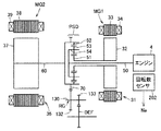
図5は、実施の形態2に係る車両200の構成を示す回路図である。車両200は、駆動用モータとエンジンを併用するハイブリッド車両である。
FIG. 5 is a circuit diagram showing a configuration of
図5を参照して、車両200は、図1で説明した車両100の構成においてモータジェネレータMGに代えてモータジェネレータMG2を含み、制御装置30に代えて制御装置230を含む。車両200は、さらに、モータジェネレータMG1と、モータジェネレータMG1に対応して設けられるインバータ22と、モータジェネレータMG1のステータコイルに流れる電流MCRT1を検知する電流センサ25と、モータジェネレータMG1の回転数Ngを検知するためのレゾルバ21と、動力分割機構PSDとを含む。
Referring to FIG. 5,
すなわち、車両200は、電池ユニット40と、モータジェネレータMG1、MG2と、動力分割機構PSDと、モータジェネレータMG1、MG2にそれぞれ対応して設けられるインバータ22,14と、昇圧コンバータ12と、レゾルバ20,21と、電流センサ24,25と、制御装置230と、図示しないエンジンおよび車輪とを含む。
That is,
電池ユニット40と昇圧コンバータ12とは、電源ラインPL1と接地ラインSLとによって電気的に接続されている。
電池ユニット40の内部の構成については、図1で示した車両100の場合と同様であるので、説明は繰返さない。
Since the internal configuration of
昇圧コンバータ12は、接地ラインSLと電源ラインPL1と間の電圧を昇圧して接地ラインSLと電源ラインPL2によってインバータ14,22に供給する。インバータ14は、昇圧コンバータ12から与えられる直流電圧を三相交流に変換してモータジェネレータMG2に出力する。インバータ22は、昇圧コンバータ12から与えられる直流電圧を三相交流に変換してモータジェネレータMG1に出力する。
昇圧コンバータ12の内部の構成については、図1で示した車両100の場合と同様であるので、説明は繰返さない。
Since the internal configuration of
インバータ14は車輪を駆動するモータジェネレータMG2に対して昇圧コンバータ12の出力する直流電圧を三相交流に変換して出力する。またインバータ14は、回生制動に伴い、モータジェネレータMG2において発電された電力を昇圧コンバータ12に戻す。このとき昇圧コンバータ12は降圧回路として動作するように制御装置230によって制御される。
インバータ14の内部の構成については、図1で示した車両100の場合と同様であるので、説明は繰返さない。
Since the internal configuration of
モータジェネレータMG2は、三相の永久磁石同期モータであり、U,V,W相の3つのコイルは各々一方端が中性点に共に接続されている。そして、U相コイルの他方端がIGBT素子Q3,Q4の接続ノードに接続される。またV相コイルの他方端がIGBT素子Q5,Q6の接続ノードに接続される。またW相コイルの他方端がIGBT素子Q7,Q8の接続ノードに接続される。 Motor generator MG2 is a three-phase permanent magnet synchronous motor, and one end of each of the three coils of U, V, and W phases is connected to a neutral point. The other end of the U-phase coil is connected to the connection node of IGBT elements Q3 and Q4. The other end of the V-phase coil is connected to a connection node of IGBT elements Q5 and Q6. The other end of the W-phase coil is connected to a connection node of IGBT elements Q7 and Q8.
電流センサ24は、モータジェネレータMG2に流れる電流をモータ電流値MCRT2として検出し、モータ電流値MCRT2を制御装置230へ出力する。
インバータ22は、昇圧コンバータ12に対してインバータ14と並列的に接続される。インバータ22は、モータジェネレータMG1に対して昇圧コンバータ12の出力する直流電圧を三相交流に変換して出力する。インバータ22は、昇圧コンバータ12から昇圧された電圧を受けてたとえばエンジンを始動させるためにモータジェネレータMG1を駆動する。
また、インバータ22は、エンジンのクランクシャフトから伝達される回転トルクによってモータジェネレータMG1で発電された電力を昇圧コンバータ12に戻す。このとき昇圧コンバータ12は降圧回路として動作するように制御装置30によって制御される。
インバータ22の内部の構成は、図示しないがインバータ14と同様であり、詳細な説明は繰返さない。
Although the internal configuration of
モータジェネレータMG1は、三相の永久磁石同期モータであり、U,V,W相の3つのコイルは各々一方端が中性点に共に接続されている。そして、各相コイルの他方端はインバータ22に接続されている。
Motor generator MG1 is a three-phase permanent magnet synchronous motor, and one end of each of three coils of U, V, and W phases is connected to a neutral point. The other end of each phase coil is connected to the
電流センサ25は、モータジェネレータMG1に流れる電流をモータ電流値MCRT1として検出し、モータ電流値MCRT1を制御装置230へ出力する。
制御装置230は、トルク指令値Tm,Tg、モータ回転数Nm,Ng、エンジン回転数Ne、電圧VB,VL,VH、電流IBの各値、モータ電流値MCRT1,MCRT2および起動信号IGONを受ける。
ここで、トルク指令値Tg,モータ回転数Ngおよびモータ電流値MCRT1はモータジェネレータMG1に関するものであり、トルク指令値Tm,モータ回転数Nmおよびモータ電流値MCRT2はモータジェネレータMG2に関するものである。 Here, torque command value Tg, motor rotation speed Ng and motor current value MCRT1 are related to motor generator MG1, and torque command value Tm, motor rotation speed Nm and motor current value MCRT2 are related to motor generator MG2.
また、電圧VBはバッテリBの電圧であり、電流IBは、バッテリBに流れる電流である。電圧VLは昇圧コンバータ12の昇圧前電圧であり、電圧VHは昇圧コンバータ12の昇圧後電圧である。
Further, the voltage VB is the voltage of the battery B, and the current IB is a current flowing through the battery B. Voltage VL is a voltage before boost of
そして制御装置230は、昇圧コンバータ12に対して昇圧指示を行なう制御信号PWU,降圧指示を行なう制御信号PWDおよび動作禁止を指示する信号CSDNを出力する。
さらに、制御装置230は、インバータ14に対して昇圧コンバータ12の出力である直流電圧VHをモータジェネレータMG2を駆動するための交流電圧に変換する駆動指示PWMI2と、モータジェネレータMG2で発電された交流電圧を直流電圧に変換して昇圧コンバータ12側に戻す回生指示PWMC2とを出力する。
Further,
さらに、制御装置230は、インバータ22に対して昇圧コンバータ12の出力である直流電圧VHをモータジェネレータMG1を駆動するための交流電圧に変換する駆動指示PWMI1と、モータジェネレータMG1で発電された交流電圧を直流電圧に変換して昇圧コンバータ12側に戻す回生指示PWMC1とを出力する。
Further,
電池ユニット40、昇圧コンバータ12および制御装置230によって車両の負荷であるインバータ14、22およびモータジェネレータMG1,MG2に電力を供給する車両用電源装置が構成されている。
図6は、図5における動力分割機構PSDの詳細を説明するための模式図である。
図6を参照して、エンジン4のクランクシャフト50とモータジェネレータMG1のロータ32とモータジェネレータMG2のロータ37とは同じ軸を中心に回転する。
FIG. 6 is a schematic diagram for explaining the details of the power split mechanism PSD in FIG.
Referring to FIG. 6,
動力分割機構PSDは、図6で示す例ではプラネタリギヤであり、クランクシャフト50に軸中心を貫通された中空のサンギヤ軸に結合されたサンギヤ51と、クランクシャフト50と同軸上を回転可能に支持されているリングギヤ52と、サンギヤ51とリングギヤ52との間に配置され、サンギヤ51の外周を自転しながら公転するピニオンギヤ53と、クランクシャフト50の端部に結合され各ピニオンギヤ53の回転軸を支持するプラネタリキャリヤ54とを含む。
The power split mechanism PSD is a planetary gear in the example shown in FIG. 6, and is supported so as to be rotatable coaxially with the
エンジン4のクランクシャフト50の回転数Neは、クランク角センサ等の回転数センサ202の出力により求められる。
The rotational speed Ne of the
動力分割機構PSDは、サンギヤ51に結合されたサンギヤ軸と、リングギヤ52に結合されたリングギヤケースおよびプラネタリキャリヤ54に結合されたクランクシャフト50の3軸が動力の入出力軸とされる。そしてこの3軸のうちいずれか2軸へ入出力される動力が決定されると、残りの1軸に入出力される動力は他の2軸へ入出力される動力に基づいて定まる。
In the power split mechanism PSD, a sun gear shaft coupled to the
動力の取出し用のカウンタドライブギヤ70がリングギヤケースの外側に設けられ、リングギヤ52と一体的に回転する。カウンタドライブギヤ70は、動力伝達減速ギヤRGに接続されている。そしてカウンタドライブギヤ70と動力伝達減速ギヤRGとの間で動力の伝達がなされる。動力伝達減速ギヤRGはディファレンシャルギヤDEFを駆動する。また、下り坂等では車輪の回転がディファレンシャルギヤDEFに伝達され、動力伝達減速ギヤRGはディファレンシャルギヤDEFによって駆動される。
A
モータジェネレータMG1は、回転磁界を形成するステータ31と、ステータ31内部に配置され複数個の永久磁石が埋込まれているロータ32とを含む。ステータ31は、ステータコア33と、ステータコア33に巻回される三相コイル34とを含む。ロータ32は、動力分割機構PSDのサンギヤ51と一体的に回転するサンギヤ軸に結合されている。ステータコア33は、電磁鋼板の薄板を積層して形成されており、図示しないケースに固定されている。
Motor generator MG1 includes a
モータジェネレータMG1は、ロータ32に埋込まれた永久磁石による磁界と三相コイル34によって形成される磁界との相互作用によりロータ32を回転駆動する電動機として動作する。またモータジェネレータMG1は、永久磁石による磁界とロータ32の回転との相互作用により三相コイル34の両端に起電力を生じさせる発電機としても動作する。
Motor generator MG1 operates as an electric motor that rotationally drives
モータジェネレータMG2は、回転磁界を形成するステータ36と、ステータ36内部に配置され複数の永久磁石が埋込まれたロータ37とを含む。ステータ36は、ステータコア38と、ステータコア38に巻回される三相コイル39とを含む。
Motor generator MG2 includes a
ロータ37は、動力分割機構PSDのリングギヤ52と一体的に回転するリングギヤケースに結合されている。ステータコア38は、たとえば電磁鋼板の薄板を積層して形成されており、図示しないケースに固定されている。
モータジェネレータMG2は、永久磁石による磁界とロータ37の回転との相互作用により三相コイル39の両端に起電力を生じさせる発電機としても動作する。またモータジェネレータMG2は、永久磁石による磁界と三相コイル39によって形成される磁界との相互作用によりロータ37を回転駆動する電動機としても動作する。
Motor generator MG2 also operates as a generator that generates electromotive force at both ends of three-
図7は、図5の制御装置230で実行される目標昇圧指令算出処理の処理構造を示したフローチャートである。このフローチャートの処理は、所定のメインルーチンから一定時間毎または所定の条件が成立する毎に呼び出されて実行される。
FIG. 7 is a flowchart showing a processing structure of a target boost command calculation process executed by
図5、図7を参照して、まず処理が開始されるとステップS11において制御装置230は、トルク指令Tm,Tgを受信する。
Referring to FIGS. 5 and 7, when the process is started,
そしてステップS12においてレゾルバ20,21の各々が正常であるか否かを判定する。レゾルバの判定については図2で説明したようにコイルLBの出力信号BとコイルLCの出力信号Cとの間にB2+C2=1が成立するか否かで判断する。
In step S12, it is determined whether or not each of the
ステップS12においてレゾルバ20,21がともに正常であると判定された場合にはステップS13に処理が進む。ステップS13においては、制御装置230は、レゾルバ20,21の出力を用いて回転数Nm,Ngを算出する。
If it is determined in step S12 that both the
一方、ステップS12においてレゾルバ20,21のいずれかが正常でないと判定された場合にはステップS14に処理が進む。ステップS14においては、制御装置230は、レゾルバ異常を運転者に報知するために警告ランプの点灯を行なう。
On the other hand, if it is determined in step S12 that one of the
そしてステップS15においてモータジェネレータMG2(モータ側)のレゾルバ20が正常であるか否かが判断される。 In step S15, it is determined whether or not resolver 20 of motor generator MG2 (motor side) is normal.
ステップS15においてモータ側のレゾルバ20が正常であると判断された場合には、制御装置230は、ステップS16において回転数Nmをレゾルバ20の出力に基づいて算出する。そしてステップS17において回転数Ngをエンジン回転数Neおよびモータ回転数Nmの関数として求める。
If it is determined in step S15 that the motor-
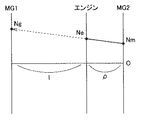
図8は、動力分割機構の共線図である。
図8に示すように、モータジェネレータMG1の回転数Ngはエンジン回転数NeとモータジェネレータMG2の回転数Nmとを結んだ直線上にある。つまり、ハイブリッド自動車である車両200は、動力分割機構としてプラネタリギヤを使用しているため、モータジェネレータMG1の回転数、エンジン回転数およびモータジェネレータMG2の回転数は図8に示すように直線上に並ぶように連動して動く。
FIG. 8 is a collinear diagram of the power split mechanism.
As shown in FIG. 8, the rotational speed Ng of motor generator MG1 is on a straight line connecting engine rotational speed Ne and rotational speed Nm of motor generator MG2. That is, since
図6でわかるように、エンジン回転数Neはプラネタリキャリヤの回転数である。モータジェネレータMG1の回転数Ngは、サンギヤ51の回転数である。モータジェネレータMG2の回転数Nmは、リングギヤ52の回転数である。
As can be seen from FIG. 6, the engine speed Ne is the speed of the planetary carrier. The rotational speed Ng of motor generator MG1 is the rotational speed of
すなわち、プラネタリギヤで結合されているので、モータジェネレータMG1の回転数Ng,エンジン回転数NeおよびモータジェネレータMG2の回転数Nmの間には次の式(1)で表わす関係が成立する。
Ne=Nm×1/(1+ρ)+Ng×ρ/(1+ρ) …(1)
この式からエンジン回転数Neと、モータジェネレータMG2の回転数NmがわかればモータジェネレータMG1の回転数Ngを求めることができる。そしてステップS17において回転数Ngを求めた後に処理はステップS21に進む。
That is, since they are coupled by planetary gears, the relationship expressed by the following equation (1) is established among the rotational speed Ng of motor generator MG1, engine rotational speed Ne, and rotational speed Nm of motor generator MG2.
Ne = Nm × 1 / (1 + ρ) + Ng × ρ / (1 + ρ) (1)
If the engine speed Ne and the motor generator MG2 rotational speed Nm are known from this equation, the motor generator MG1 rotational speed Ng can be obtained. And after calculating | requiring the rotation speed Ng in step S17, a process progresses to step S21.
次にステップS15においてモータのレゾルバ20が正常でないと判断された場合には、モータジェネレータMG1側(ジェネレータ側)のレゾルバ21が正常であるか否かが判断される。ここでレゾルバ21が正常であると判断された場合には処理はステップS19に進み、レゾルバ21の出力から回転数Ngが算出される。そしてステップS20において、制御装置230は、回転数Nmを回転数NgおよびNeの関数として求める。この関係については図8で示した場合と同様な理由により回転数Ngおよび回転数Neが定まれば回転数Nmを求めることができる。
Next, when it is determined in step S15 that the
ステップS20の処理が終了するとステップS21の処理が実行される。
一方ステップS18においてレゾルバ21も異常であると判断された場合には回転数を求めることができないのでステップS23に進み、実施の形態1と同様に目標昇圧指令値を最大値のVHmaxに設定する。そしてステップS24において制御はメインルーチンに戻される。
When the process of step S20 ends, the process of step S21 is executed.
On the other hand, if it is determined in step S18 that the
一方、ステップS13またはS17またはS20の処理が実行された後には、ステップS21において必要昇圧値の算出が行なわれる。この昇圧値の算出については、モータジェネレータMG1に対応する図4に示したようなマップからトルク指令値Tgと回転数NgからMG1側の必要昇圧値VHgが算出され、モータジェネレータMG2に対応する図4に示すようなマップからトルク指令値Tmおよび回転数Nmに基づいて必要昇圧値VHmが算出される。 On the other hand, after the process of step S13, S17 or S20 is executed, the required boost value is calculated in step S21. Regarding the calculation of the boost value, the required boost value VHg on the MG1 side is calculated from the torque command value Tg and the rotational speed Ng from the map shown in FIG. 4 corresponding to the motor generator MG1, and the diagram corresponding to the motor generator MG2. The required boost value VHm is calculated based on the torque command value Tm and the rotational speed Nm from the map as shown in FIG.
そしてステップS22において目標昇圧指令として必要昇圧値VHmと必要昇圧値VHgのいずれか大きいほうを目標昇圧指令値VHとして定める。そしてステップS24に処理が進み制御はメインルーチンに移される。 In step S22, the larger one of the necessary boost value VHm and the necessary boost value VHg is determined as the target boost command value VH as the target boost command. Then, the process proceeds to step S24, and the control is moved to the main routine.
以上の説明をもとに、実施の形態2について再び図5、図6を参照して総括する。
車両は、モータジェネレータMG1、MG2と、モータジェネレータMG1、MG2をそれぞれ駆動するインバータ22,14と、エンジン4と、モータジェネレータMG1の回転軸、モータジェネレータMG2の回転軸およびエンジン4のクランクシャフト50と機械的に結合される動力分割機構PSDとを含む。車両の電源装置は、蓄電装置であるバッテリBと、蓄電装置の電圧を昇圧してインバータ22,14に供給する昇圧コンバータ12と、昇圧コンバータ12に対して、モータジェネレータMG1、MG2の目標動作状態に応じた昇圧電圧目標値を指示する制御装置230とを含む。制御装置230は、モータジェネレータMG1、MG2のうちの一方の現在の動作状態信号が正常でないと判断した場合に、モータジェネレータMG1、MG2のうちの他方の現在の動作状態信号とエンジンの運転状態を示す信号に基づいて、モータジェネレータMG1、MG2のうちの一方の現在の動作状態信号を予測する。
Based on the above description, the second embodiment will be summarized with reference to FIGS. 5 and 6 again.
The vehicle includes motor generators MG1 and MG2,
より好ましくは、車両は、モータジェネレータMG1のロータの回転数Ngを検知するレゾルバ21と、モータジェネレータMG2のロータの回転数Nmを検知するレゾルバ20と、エンジン4のクランクシャフト50の回転数Neを検知する回転数センサ202とをさらに含む。動力分割機構PSDは、2軸の入力が決まれば他の1軸の入力が定まる遊星歯車機構を含む。
More preferably, the vehicle uses a
実施の形態2によれば、他の回転数検出手段により電動機の回転数の算出が可能である場合にはこれを用いることにより昇圧コンバータの出力電圧を最大値まで引上げるよりも効率のよい走行をすることが可能となる。 According to the second embodiment, when the number of rotations of the electric motor can be calculated by another number of rotation number detection means, the use of this makes it possible to travel more efficiently than raising the output voltage of the boost converter to the maximum value. It becomes possible to do.
[実施の形態3]
ハイブリッド車両には、前輪駆動用のモータに加え後輪駆動用のモータを搭載する四輪駆動車も存在する。後輪を前輪駆動用モータと独立したモータで駆動させることにより、一般的な四輪駆動システムに必要不可欠なトランスファやプロペラシャフトが不要となる。これにより駆動ロスの低減が図れ、後輪用モータジェネレータによる回生発電の効果もあいまって通常の四輪駆動車よりも低燃費走行が期待できる。
[Embodiment 3]
Among hybrid vehicles, there are also four-wheel drive vehicles equipped with a motor for driving rear wheels in addition to a motor for driving front wheels. By driving the rear wheels by a motor independent of the front wheel drive motor, a transfer and a propeller shaft, which are indispensable for a general four-wheel drive system, become unnecessary. As a result, driving loss can be reduced, and combined with the effect of regenerative power generation by the motor generator for the rear wheels, it is possible to expect low fuel consumption travel compared to ordinary four-wheel drive vehicles.
図9は、実施の形態3に係るハイブリッド車両300の構成を示したブロック図である。
FIG. 9 is a block diagram showing a configuration of
図9を参照して、車両300は、電池ユニット40と、昇圧コンバータ12と、インバータ14,22と、モータジェネレータMG1,MG2と、エンジン4と、動力分割機構PSDと、レゾルバ20,21とを含む。以上の構成要素については実施の形態2の車両200と共通であるので説明は繰返さない。
Referring to FIG. 9,
車両300は、さらに、インバータ302と、モータジェネレータMGRと、レゾルバ304と、車輪速センサ306と、制御装置330とを含む。
インバータ302は、後輪RWを駆動するためのモータジェネレータMGRに対応するインバータである。レゾルバ304は、モータジェネレータMGRのロータの回転を検出する。これに加え、スキッドコントロール等のために後輪RWの車輪速VRR,VRLを検知する車輪速センサ306が設けられている。
制御装置330は、トルク指令値Tm,Tg、Tr、モータ回転数Nm,Ng、Nr、エンジン回転数Ne、電圧VB,VL,VH、電流IBの各値、および起動信号IGONを受ける。
ここで、トルク指令値Tgおよびモータ回転数NgはモータジェネレータMG1に関するものであり、トルク指令値Tmおよびモータ回転数NmはモータジェネレータMG2に関するものである。トルク指令値Trおよびモータ回転数NrはモータジェネレータMGRに関するものである。 Here, torque command value Tg and motor rotational speed Ng relate to motor generator MG1, and torque command value Tm and motor rotational speed Nm relate to motor generator MG2. Torque command value Tr and motor rotation speed Nr relate to motor generator MGR.
また、電圧VBはバッテリBの電圧であり、電流IBは、バッテリBに流れる電流である。電圧VLは昇圧コンバータ12の昇圧前電圧であり、電圧VHは昇圧コンバータ12の昇圧後電圧である。
Further, the voltage VB is the voltage of the battery B, and the current IB is a current flowing through the battery B. Voltage VL is a voltage before boost of
そして制御装置330は、昇圧コンバータ12に対して昇圧指示を行なう制御信号PWU,降圧指示を行なう制御信号PWDおよび動作禁止を指示する信号CSDNを出力する。
さらに、制御装置330は、インバータ22,14,302の各々に対して昇圧コンバータ12の出力である直流電圧VHをモータジェネレータを駆動するための交流電圧に変換する駆動指示PWMIと、モータジェネレータで発電された交流電圧を直流電圧に変換して昇圧コンバータ12側に戻す回生指示PWMCとを出力する。
Further,
電池ユニット40、昇圧コンバータ12および制御装置330によって車両の負荷であるインバータ14、22,302およびモータジェネレータMG1,MG2,MGRに電力を供給する車両用電源装置が構成されている。
図10は、図9の制御装置330で行なわれる昇圧指令値の算出処理を示したフローチャートである。
FIG. 10 is a flowchart showing a boost command value calculation process performed by
図9、図10を参照して、制御装置330は、図7で既に説明したモータジェネレータMG1,MG2についての処理の後に図10のフローチャートに示した処理を実行する。
Referring to FIGS. 9 and 10,
まず処理が開始されると、ステップS51においてモータジェネレータMGRに対するトルク指令Trの受信が行なわれる。そしてステップS52においてモータジェネレータMGRの回転を検知するレゾルバ304が正常であるか否かが判定される。この判定は実施の形態1で説明したレゾルバ20の判定と同様な方法により行なわれる。
When the process is started, torque command Tr is received for motor generator MGR in step S51. In step S52, it is determined whether or not resolver 304 that detects the rotation of motor generator MGR is normal. This determination is performed by the same method as the determination of the
ステップS52においてレゾルバ304の出力が正常であると判断された場合には制御装置330はレゾルバ304の出力から回転数Nrを算出する。一方、ステップS52においてレゾルバ304の出力が正常でないと判断された場合にはステップS54に処理が進む。
When it is determined in step S52 that the output of the
ステップS54においては後輪の車輪速センサ306で検知された車輪速VRR,VRLを用いてこれらの関数として回転数Nrを算出する。ステップS53またはS54の処理が終了するとステップS55に処理が進む。
In step S54, the rotational speed Nr is calculated as a function of these using the wheel speeds VRR and VRL detected by the rear
ステップS55においては図4と同様なモータジェネレータMGR用のマップに基づいて必要昇圧値VHrを算出する。そしてステップS56において図7のフローチャートで求めておいた目標昇圧指令値VHとステップS55で求めた必要昇圧値VHrとの大小比較がなされる。ここでVH>VHrが成立しなかった場合にはステップS57に進み目標昇圧値VHをVHrにセットする。一方、ステップS56において求めておいた目標昇圧値のほうがステップS55で求めた必要昇圧値よりも高ければそのままステップS58に進み処理はメインルーチンに移される。 In step S55, the required boost value VHr is calculated based on the same motor generator MGR map as in FIG. In step S56, the target boost command value VH obtained in the flowchart of FIG. 7 is compared with the required boost value VHr obtained in step S55. If VH> VHr is not satisfied, the process proceeds to step S57, and the target boost value VH is set to VHr. On the other hand, if the target boost value obtained in step S56 is higher than the required boost value obtained in step S55, the process proceeds to step S58 and the process is moved to the main routine.
以上の説明をもとに、実施の形態3について再び図9を参照して総括する。
車両300は、車両の速度に応じた回転を行なう複数のモータジェネレータMG1,MG2,MGRと、モータジェネレータMG1,MG2,MGRをそれぞれ駆動する複数のインバータ22,14,302とを含む。車両の電源装置は、蓄電装置である電池ユニット40と、蓄電装置の電圧を昇圧して複数のインバータに共通の昇圧電圧を供給する昇圧コンバータ12と、モータジェネレータMG1,MG2,MGRの目標動作状態からモータジェネレータMG1,MG2,MGRの必要電圧のうちから最大電圧を求めて、昇圧コンバータ12に対して、最大電圧を昇圧電圧目標値として指示する制御装置330とを含む。制御装置330は、モータジェネレータMG1,MG2,MGRの現在の動作状態信号の少なくともいずれか1つが正常でないと判断した場合に、昇圧電圧目標値を最大値まで増加させる。
Based on the above description, Embodiment 3 will be summarized again with reference to FIG.
好ましくは、車両300は、複数の回転電機のロータの回転数をそれぞれ検知する複数の回転数センサとしてレゾルバ20,21および回転数センサ202を含む。制御装置330は、複数の回転数センサの少なくともいずれか1つの出力が所定条件を満たさない場合に動作状態信号が正常でないと判断する。
Preferably,
実施の形態3は他の局面に従うと以下のようにも言うことができる。車両は、車両の速度を検知する検知部である車輪速センサ306と、車両の速度に応じた回転を行なう複数の回転電機であるモータジェネレータMG1,MG2,MGRと、複数の回転電機をそれぞれ駆動する複数のインバータ22,14,302とを含む。車両の電源装置は、蓄電装置である電池ユニット40と、蓄電装置の電圧を昇圧して複数のインバータ22,14,302に共通の昇圧電圧を供給する昇圧コンバータ12と、複数の回転電機の目標動作状態から複数の回転電機の必要電圧のうちから最大電圧を求めて、昇圧コンバータ12に対して、最大電圧を昇圧電圧目標値として指示する制御装置330とを含む。制御装置330は、複数の回転電機の現在の動作状態信号のいずれかが正常でないと判断した場合に、車輪速センサ306の出力から正常な動作状態信号を求めて昇圧電圧目標値の決定に使用する。
Embodiment 3 can also be described as follows in accordance with other aspects. The vehicle drives a
以上説明したように、実施の形態3においては複数のモータジェネレータを搭載する車両において目標動作点が正常でない場合においても昇圧コンバータの出力電圧がモータの逆起電圧を下回ることを避けることができ、誤った回生制動が防止され制御性の悪化を防止できる。 As described above, in the third embodiment, even when the target operating point is not normal in a vehicle equipped with a plurality of motor generators, it is possible to prevent the output voltage of the boost converter from falling below the counter electromotive voltage of the motor. Incorrect regenerative braking is prevented, and deterioration of controllability can be prevented.
今回開示された実施の形態はすべての点で例示であって制限的なものではないと考えられるべきである。本発明の範囲は上記した説明ではなくて特許請求の範囲によって示され、特許請求の範囲と均等の意味および範囲内でのすべての変更が含まれることが意図される。 The embodiment disclosed this time should be considered as illustrative in all points and not restrictive. The scope of the present invention is defined by the terms of the claims, rather than the description above, and is intended to include any modifications within the scope and meaning equivalent to the terms of the claims.
4 エンジン、6,8,10 電圧センサ、11,24,25 電流センサ、12 昇圧コンバータ、14,22,302 インバータ、15 U相アーム、16 V相アーム、17 W相アーム、20,21,304 レゾルバ、30,230,330 制御装置、31,36 ステータ、32,37 ロータ、33,38 ステータコア、34,39 三相コイル、40 電池ユニット、50 クランクシャフト、51 サンギヤ、52 リングギヤ、53 ピニオンギヤ、54 プラネタリキャリヤ、70 カウンタドライブギヤ、100,200,300 車両、202 回転数センサ、306 車輪速センサ、B バッテリ、C2 平滑用コンデンサ、D1〜D8 ダイオード、DEF ディファレンシャルギヤ、L1 リアクトル、LA,LB,LC コイル、MG,MG1,MG2,MGR モータジェネレータ、PL1,PL2 電源ライン、PSD 動力分割機構、Q1〜Q8 IGBT素子、R 制限抵抗、RG 動力伝達減速ギヤ、RT ロータ、RW 後輪、SL 接地ライン、SMR1〜SMR3 システムメインリレー、ST ステータ。 4 Engine, 6, 8, 10 Voltage sensor, 11, 24, 25 Current sensor, 12 Boost converter, 14, 22, 302 Inverter, 15 U-phase arm, 16 V-phase arm, 17 W-phase arm, 20, 21, 304 Resolver, 30, 230, 330 Controller, 31, 36 Stator, 32, 37 Rotor, 33, 38 Stator core, 34, 39 Three-phase coil, 40 Battery unit, 50 Crankshaft, 51 Sun gear, 52 Ring gear, 53 Pinion gear, 54 Planetary carrier, 70 Counter drive gear, 100, 200, 300 Vehicle, 202 Speed sensor, 306 Wheel speed sensor, B battery, C2 smoothing capacitor, D1-D8 diode, DEF differential gear, L1 reactor, LA, LB, LC Coil, MG, MG1, MG2, MGR Motor generator, PL1, PL2 power line, PSD power split mechanism, Q1-Q8 IGBT element, R limiting resistor, RG power transmission reduction gear, RT rotor, RW rear wheel, SL ground line, SMR1-SMR3 System main relay, ST stator.
Claims (11)
蓄電装置と、
前記蓄電装置の電圧を昇圧して前記インバータに供給する電圧変換部と、
前記電圧変換部に対して、前記動作状態検知手段が出力する第1の動作状態信号に応じて昇圧電圧目標値を指示する制御装置とを含み、
前記制御装置は、前記動作状態検知手段が正常でないと判断した場合に、前記第1の動作状態信号を使用せずに前記昇圧電圧目標値を定めて前記電圧変換部の動作を維持させ、
前記制御装置は、前記動作状態検知手段が正常でないと判断した場合には前記昇圧電圧目標値を設定可能上限値に定める、車両の電源装置。 A power supply device for a vehicle, comprising: a first rotating electrical machine; an inverter that drives the first rotating electrical machine; and an operating state detecting unit that detects an operating state of the first rotating electrical machine.
A power storage device;
A voltage converter that boosts the voltage of the power storage device and supplies the boosted voltage to the inverter;
A control device for instructing a boost voltage target value in accordance with a first operation state signal output from the operation state detection unit to the voltage conversion unit;
When the control device determines that the operation state detection means is not normal, the control device determines the boost voltage target value without using the first operation state signal, and maintains the operation of the voltage converter.
The said control apparatus is a power supply device of a vehicle which determines the said boost voltage target value to a settable upper limit value, when it determines that the said operation state detection means is not normal.
前記第1の回転電機のロータの回転数を検知する第1の回転数センサを含み、
前記制御装置は、前記第1の回転数センサの出力が所定条件を満たさない場合に前記動作状態検知手段が正常でないと判断する、請求項1に記載の車両の電源装置。 The operating state detecting means is
A first rotational speed sensor for detecting the rotational speed of the rotor of the first rotating electrical machine;
The power supply device for a vehicle according to claim 1, wherein the control device determines that the operation state detection means is not normal when an output of the first rotation speed sensor does not satisfy a predetermined condition.
コイルを含み、
前記車両は、
前記コイルに流れる電流を検知する電流センサをさらに含み、
前記制御装置は、前記電流センサの出力が所定条件を満たさない場合に前記動作状態検知手段が正常でないと判断する、請求項1に記載の車両の電源装置。 The first rotating electric machine is:
Including coils,
The vehicle is
A current sensor for detecting a current flowing through the coil;
The power supply device for a vehicle according to claim 1, wherein the control device determines that the operation state detection means is not normal when the output of the current sensor does not satisfy a predetermined condition.
複数の回転電機を含み、
前記第1の回転電機は、前記複数の回転電機のうちの1つであり、
前記インバータは、
前記複数の回転電機をそれぞれ駆動する複数のインバータユニットとを含み、
前記電圧変換部は、前記蓄電装置の電圧を昇圧して前記複数のインバータユニットに共通の昇圧電圧を供給し、
前記制御装置は、前記複数の回転電機の動作状態に基づき前記複数の回転電機が必要とする複数の電圧のうちから最大電圧を求めて、前記電圧変換部に対して、前記最大電圧を昇圧電圧目標値として指示し、
前記制御装置は、前記複数の回転電機の動作状態をそれぞれ検出する複数の動作状態検知手段のいずれかが正常でないと判断した場合には、前記昇圧電圧目標値を設定可能上限値まで増加させる、請求項1に記載の車両の電源装置。 The vehicle is
Including a plurality of rotating electrical machines,
The first rotating electrical machine is one of the plurality of rotating electrical machines,
The inverter is
A plurality of inverter units that respectively drive the plurality of rotating electrical machines,
The voltage conversion unit boosts the voltage of the power storage device to supply a common boosted voltage to the plurality of inverter units ,
The control device obtains a maximum voltage from a plurality of voltages required by the plurality of rotating electrical machines based on an operating state of the plurality of rotating electrical machines, and outputs the maximum voltage to the voltage conversion unit as a boost voltage. As a target value,
The control device increases the boost voltage target value to a settable upper limit value when it is determined that any one of the plurality of operation state detection means for detecting the operation states of the plurality of rotating electrical machines is not normal, The power supply device for a vehicle according to claim 1.
前記複数の回転電機のロータの回転数をそれぞれ検知する複数の回転数センサを含み、
前記制御装置は、前記複数の回転数センサの少なくともいずれか1つの出力が所定条件を満たさない場合には、対応する回転電機の動作状態を検知する動作状態検知手段が正常でないと判断する、請求項4に記載の車両の電源装置。 The plurality of operation state detection means include
A plurality of rotation speed sensors that respectively detect the rotation speeds of the rotors of the plurality of rotating electrical machines;
The control device determines that an operation state detection unit that detects an operation state of a corresponding rotating electrical machine is not normal when an output of at least one of the plurality of rotation speed sensors does not satisfy a predetermined condition. Item 5. The vehicle power supply device according to Item 4.
前記電源装置は、
蓄電装置と、
前記蓄電装置の電圧を昇圧して前記インバータに供給する電圧変換部とを含み、
前記制御方法は、
前記電圧変換部に対して、前記動作状態検知手段が出力する第1の動作状態信号に応じて昇圧電圧目標値を指示するステップと、
前記動作状態検知手段が正常でないと判断した場合に、前記第1の動作状態信号を使用せずに前記昇圧電圧目標値を定めて前記電圧変換部の動作を維持させるステップとを含み、
前記電圧変換部の動作を維持させるステップにおいて、前記動作状態検知手段が正常でないと判断した場合には、前記昇圧電圧目標値は、設定可能上限値に定められる、車両の電源装置の制御方法。 A control method for a power supply device for a vehicle, comprising: a first rotating electrical machine; an inverter that drives the first rotating electrical machine; and an operating state detection unit that detects an operating state of the first rotating electrical machine.
The power supply device
A power storage device;
A voltage converter that boosts the voltage of the power storage device and supplies the boosted voltage to the inverter;
The control method is:
Instructing the voltage converter in accordance with a first operating state signal output by the operating state detector, a boost voltage target value;
Wherein when the operating state detection means is determined not to be normal, and a step of maintaining the boosted voltage target value operation of the voltage conversion section defining a without using the first operation state signal,
In the step of maintaining the operation of the voltage conversion unit, when it is determined that the operation state detection means is not normal, the boost voltage target value is set to a settable upper limit value.
前記第1の回転電機のロータの回転数を検知する第1の回転数センサを含み、
前記制御方法は、
前記第1の回転数センサの出力が所定条件を満たさない場合に前記動作状態検知手段が正常でないと判断するステップをさらに含む、請求項7に記載の車両の電源装置の制御方法。 The operating state detecting means is
A first rotational speed sensor for detecting the rotational speed of the rotor of the first rotating electrical machine;
The control method is:
The method of controlling a vehicle power supply device according to claim 7, further comprising a step of determining that the operation state detection means is not normal when the output of the first rotation speed sensor does not satisfy a predetermined condition.
コイルを含み、
前記車両は、
前記コイルに流れる電流を検知する電流センサをさらに含み、
前記制御方法は、
前記電流センサの出力が所定条件を満たさない場合に前記動作状態検知手段が正常でないと判断するステップをさらに含む、請求項7に記載の車両の電源装置の制御方法。 The first rotating electric machine is:
Including coils,
The vehicle is
A current sensor for detecting a current flowing through the coil;
The control method is:
The method of controlling a vehicle power supply device according to claim 7, further comprising a step of determining that the operation state detection means is not normal when the output of the current sensor does not satisfy a predetermined condition.
複数の回転電機を含み、
前記第1の回転電機は、前記複数の回転電機のうちの1つであり、
前記インバータは、
前記複数の回転電機をそれぞれ駆動する複数のインバータユニットを含み、
前記電圧変換部は、前記蓄電装置の電圧を昇圧して前記複数のインバータユニットに共通の昇圧電圧を供給し、
前記制御方法は、
前記複数の回転電機の動作状態に基づき前記複数の回転電機がそれぞれ必要とする複数の電圧のうちから最大電圧を求めて、前記電圧変換部に対して、前記最大電圧を昇圧電圧目標値として指示するステップと、
前記複数の回転電機の動作状態をそれぞれ示す複数の動作状態検知手段の少なくともいずれかが正常でないと判断した場合には、前記昇圧電圧目標値を設定可能上限値まで増加させるステップをさらに含む、請求項7に記載の車両の電源装置の制御方法。 The vehicle is
Including a plurality of rotating electrical machines,
The first rotating electrical machine is one of the plurality of rotating electrical machines,
The inverter is
Including a plurality of inverter units that respectively drive the plurality of rotating electrical machines;
The voltage conversion unit boosts the voltage of the power storage device to supply a common boosted voltage to the plurality of inverter units,
The control method is:
A maximum voltage is obtained from a plurality of voltages required by each of the plurality of rotating electrical machines based on operating states of the plurality of rotating electrical machines, and the maximum voltage is indicated as a boost voltage target value to the voltage converter. And steps to
The method further includes the step of increasing the boost voltage target value to a settable upper limit value when it is determined that at least one of the plurality of operation state detection units each indicating the operation state of the plurality of rotating electrical machines is not normal. Item 8. A control method for a vehicle power supply device according to Item 7.
前記複数の回転電機のロータの回転数をそれぞれ検知する複数の回転数センサを含み、
前記制御方法は、
前記複数の回転数センサの少なくともいずれか1つの出力が所定条件を満たさない場合には、対応する回転電機の動作状態を検知する動作状態検知手段が正常でないと判断するステップをさらに含む、請求項10に記載の車両の電源装置の制御方法。 The plurality of operation state detection means include
A plurality of rotation speed sensors that respectively detect the rotation speeds of the rotors of the plurality of rotating electrical machines;
The control method is:
The method further includes a step of determining that an operation state detection unit that detects an operation state of a corresponding rotating electrical machine is not normal when an output of at least one of the plurality of rotation speed sensors does not satisfy a predetermined condition. The control method of the power supply device of the vehicle of 10.
Priority Applications (8)
| Application Number | Priority Date | Filing Date | Title |
|---|---|---|---|
| JP2006018055A JP4622872B2 (en) | 2006-01-26 | 2006-01-26 | VEHICLE POWER DEVICE, VEHICLE, AND CONTROL METHOD FOR VEHICLE POWER DEVICE |
| DE602006014447T DE602006014447D1 (en) | 2006-01-26 | 2006-12-26 | ENERGY SOURCE DEVICE FOR A VEHICLE, VEHICLE AND METHOD FOR CONTROLLING AN ENERGY SOURCE APPARATUS |
| US12/084,648 US7781999B2 (en) | 2006-01-26 | 2006-12-26 | Power source apparatus for vehicle, vehicle and method of controlling power source apparatus |
| PCT/JP2006/326351 WO2007086235A1 (en) | 2006-01-26 | 2006-12-26 | Power source apparatus for vehicle, vehicle and method of controlling power source apparatus |
| AU2006336711A AU2006336711B2 (en) | 2006-01-26 | 2006-12-26 | Power source apparatus for vehicle, vehicle and method of controlling power source apparatus |
| CN2006800517702A CN101336173B (en) | 2006-01-26 | 2006-12-26 | Power source apparatus for vehicle, vehicle and method of controlling power source apparatus |
| KR1020087020820A KR100985837B1 (en) | 2006-01-26 | 2006-12-26 | Power source apparatus for vehicle, vehicle and method of controlling power source apparatus |
| EP06843723A EP1981733B1 (en) | 2006-01-26 | 2006-12-26 | Power source apparatus for vehicle, vehicle and method of controlling power source apparatus |
Applications Claiming Priority (1)
| Application Number | Priority Date | Filing Date | Title |
|---|---|---|---|
| JP2006018055A JP4622872B2 (en) | 2006-01-26 | 2006-01-26 | VEHICLE POWER DEVICE, VEHICLE, AND CONTROL METHOD FOR VEHICLE POWER DEVICE |
Publications (3)
| Publication Number | Publication Date |
|---|---|
| JP2007202311A JP2007202311A (en) | 2007-08-09 |
| JP2007202311A5 JP2007202311A5 (en) | 2008-05-01 |
| JP4622872B2 true JP4622872B2 (en) | 2011-02-02 |
Family
ID=37908284
Family Applications (1)
| Application Number | Title | Priority Date | Filing Date |
|---|---|---|---|
| JP2006018055A Active JP4622872B2 (en) | 2006-01-26 | 2006-01-26 | VEHICLE POWER DEVICE, VEHICLE, AND CONTROL METHOD FOR VEHICLE POWER DEVICE |
Country Status (8)
| Country | Link |
|---|---|
| US (1) | US7781999B2 (en) |
| EP (1) | EP1981733B1 (en) |
| JP (1) | JP4622872B2 (en) |
| KR (1) | KR100985837B1 (en) |
| CN (1) | CN101336173B (en) |
| AU (1) | AU2006336711B2 (en) |
| DE (1) | DE602006014447D1 (en) |
| WO (1) | WO2007086235A1 (en) |
Families Citing this family (48)
| Publication number | Priority date | Publication date | Assignee | Title |
|---|---|---|---|---|
| JP4679891B2 (en) * | 2004-11-30 | 2011-05-11 | トヨタ自動車株式会社 | AC voltage generator and power output device |
| JP4114697B2 (en) * | 2006-06-23 | 2008-07-09 | ダイキン工業株式会社 | Inverter control method |
| JP5188783B2 (en) * | 2007-11-14 | 2013-04-24 | アイシン・エィ・ダブリュ株式会社 | Vehicle drive system |
| JP5018516B2 (en) * | 2008-01-31 | 2012-09-05 | アイシン・エィ・ダブリュ株式会社 | Rotating electrical machine control device |
| JP4424428B2 (en) | 2008-03-18 | 2010-03-03 | トヨタ自動車株式会社 | Electric motor drive control device, vehicle including the same, and electric motor drive control method |
| JP4670882B2 (en) * | 2008-03-18 | 2011-04-13 | トヨタ自動車株式会社 | Electric motor drive control device, vehicle including the same, and electric motor drive control method |
| JP4969503B2 (en) * | 2008-04-16 | 2012-07-04 | 三菱電機株式会社 | VEHICLE POWER CONVERSION DEVICE AND VEHICLE DRIVE CONTROL DEVICE |
| JP4969504B2 (en) * | 2008-04-16 | 2012-07-04 | 三菱電機株式会社 | VEHICLE POWER CONVERSION DEVICE AND VEHICLE DRIVE CONTROL DEVICE |
| JP5178400B2 (en) * | 2008-08-28 | 2013-04-10 | 株式会社東芝 | Washing and drying machine |
| JP5412839B2 (en) * | 2009-01-13 | 2014-02-12 | トヨタ自動車株式会社 | Power supply device, control method therefor, and vehicle |
| JP5471255B2 (en) * | 2009-09-30 | 2014-04-16 | アイシン・エィ・ダブリュ株式会社 | Control device for motor drive device |
| US8666579B2 (en) | 2009-10-13 | 2014-03-04 | Honda Motor Co., Ltd. | Hybrid vehicle |
| JP5354818B2 (en) * | 2009-10-13 | 2013-11-27 | 本田技研工業株式会社 | Hybrid vehicle |
| JP5348808B2 (en) | 2009-10-13 | 2013-11-20 | 本田技研工業株式会社 | Hybrid vehicle |
| JP5083305B2 (en) * | 2009-12-24 | 2012-11-28 | 株式会社デンソー | Electric motor drive device and electric power steering device using the same |
| WO2011132269A1 (en) * | 2010-04-21 | 2011-10-27 | トヨタ自動車株式会社 | Control device for motor drive system and vehicle having same |
| JP5234050B2 (en) * | 2010-04-27 | 2013-07-10 | 株式会社デンソー | Vehicle power supply |
| JP5229645B2 (en) | 2010-06-24 | 2013-07-03 | 株式会社デンソー | Electric motor drive device and electric power steering device using the same |
| JP5195888B2 (en) * | 2010-06-24 | 2013-05-15 | 株式会社デンソー | Electric motor drive device and electric power steering device using the same |
| JP5229644B2 (en) | 2010-06-24 | 2013-07-03 | 株式会社デンソー | Electric motor drive device and electric power steering device using the same |
| WO2012011155A1 (en) * | 2010-07-23 | 2012-01-26 | 三菱電機株式会社 | Control apparatus and control method for an ac rotary machine |
| EP2600518B1 (en) * | 2010-07-27 | 2019-10-09 | Mitsubishi Electric Corporation | Control apparatus for ac rotating machine |
| JP2012066624A (en) * | 2010-09-21 | 2012-04-05 | Suzuki Motor Corp | Power generation control device for electric vehicle |
| CN103221249B (en) * | 2010-11-22 | 2015-06-17 | 雅马哈发动机株式会社 | Two-wheeled electric vehicle |
| KR101172331B1 (en) * | 2010-12-07 | 2012-08-09 | 현대자동차주식회사 | System for controlling motor of vehicle |
| CN103269898B (en) * | 2010-12-20 | 2015-09-23 | 丰田自动车株式会社 | Elec. vehicle and control method thereof |
| JP5189659B2 (en) * | 2011-01-13 | 2013-04-24 | 三菱電機株式会社 | Resolver abnormality detection device |
| JP5329574B2 (en) * | 2011-01-25 | 2013-10-30 | 住友重機械工業株式会社 | Hybrid construction machine |
| JP5413420B2 (en) * | 2011-08-08 | 2014-02-12 | 株式会社デンソー | Rotating machine control device |
| JP5661008B2 (en) | 2011-09-06 | 2015-01-28 | トヨタ自動車株式会社 | Motor control system |
| CN103023426A (en) * | 2011-09-28 | 2013-04-03 | 西门子公司 | Motor driver and motor driving method |
| WO2013051194A1 (en) * | 2011-10-06 | 2013-04-11 | ヤマハ発動機株式会社 | Electric vehicle |
| FR2989543B1 (en) * | 2012-04-11 | 2014-03-28 | Valeo Sys Controle Moteur Sas | METHOD FOR CONTROLLING AN ELECTRICAL PROPULSION CHAIN OF A VEHICLE |
| JP6062324B2 (en) * | 2013-06-14 | 2017-01-18 | 日立オートモティブシステムズ株式会社 | Engine starter and engine start control method |
| JP5971265B2 (en) * | 2014-01-20 | 2016-08-17 | トヨタ自動車株式会社 | Boost converter controller |
| CN104842993B (en) * | 2014-02-18 | 2019-04-12 | 株式会社斯巴鲁 | The control device of cell voltage and the control method of cell voltage |
| JP6197690B2 (en) * | 2014-02-21 | 2017-09-20 | トヨタ自動車株式会社 | Motor control system |
| JP6335040B2 (en) * | 2014-06-20 | 2018-05-30 | 株式会社東芝 | Vehicle control device |
| JP6350208B2 (en) * | 2014-10-24 | 2018-07-04 | トヨタ自動車株式会社 | Automobile |
| JP6497298B2 (en) * | 2015-11-10 | 2019-04-10 | 株式会社デンソー | Abnormality diagnosis device |
| JP6272291B2 (en) * | 2015-12-24 | 2018-01-31 | 株式会社Subaru | Vehicle power supply |
| JP6558291B2 (en) * | 2016-04-01 | 2019-08-14 | 株式会社デンソー | Motor control device |
| US10782155B2 (en) * | 2016-09-09 | 2020-09-22 | Kabushiki Kaisha Toshiba | Angle detection apparatus and integrated circuit |
| US10500966B2 (en) * | 2016-12-01 | 2019-12-10 | Ford Global Technologies, Llc | Adaptive boost voltage for hybrid vehicle operation |
| JP6933469B2 (en) * | 2017-02-10 | 2021-09-08 | 株式会社コロナ | Motor control circuit, motor control method, and program |
| JP6790980B2 (en) * | 2017-04-12 | 2020-11-25 | トヨタ自動車株式会社 | Hybrid vehicle and its control method |
| US11186199B2 (en) * | 2019-11-22 | 2021-11-30 | Toyota Motor Engineering & Manufacturing North America, Inc. | HEV battery SOC meter and boost power display |
| US11296644B2 (en) * | 2020-01-20 | 2022-04-05 | Ford Global Technologies, Llc | Alternating passive rectification and 3-phase-short control for motor fault protection |
Citations (3)
| Publication number | Priority date | Publication date | Assignee | Title |
|---|---|---|---|---|
| JPH06225402A (en) * | 1993-01-21 | 1994-08-12 | Toyota Motor Corp | Controller for electric motor vehicle |
| JPH0923508A (en) * | 1995-07-07 | 1997-01-21 | Honda Motor Co Ltd | Controller for electric motor car |
| JP2003189599A (en) * | 2001-12-20 | 2003-07-04 | Toyota Motor Corp | Voltage conversion unit and voltage conversion method |
Family Cites Families (9)
| Publication number | Priority date | Publication date | Assignee | Title |
|---|---|---|---|---|
| JP2861680B2 (en) * | 1992-10-13 | 1999-02-24 | 株式会社日立製作所 | Failure detection method for electric vehicles and fail-safe control method using the same |
| JPH08140202A (en) * | 1994-11-07 | 1996-05-31 | Hitachi Ltd | Protective apparatus for electric motor vehicle and protecting method therefor |
| JP3746334B2 (en) | 1996-08-22 | 2006-02-15 | トヨタ自動車株式会社 | Permanent magnet type synchronous motor drive control apparatus and method |
| WO2003061104A1 (en) * | 2002-01-16 | 2003-07-24 | Toyota Jidosha Kabushiki Kaisha | Voltage converter control apparatus, voltage conversion method, storage medium, program, drive system, and vehicle having the drive system |
| DE10223384A1 (en) * | 2002-05-25 | 2003-12-04 | Conti Temic Microelectronic | Method for operating an electric motor |
| JP3928559B2 (en) | 2003-01-10 | 2007-06-13 | トヨタ自動車株式会社 | Voltage conversion apparatus, computer-readable recording medium storing a program for causing a computer to execute failure processing, and a failure processing method |
| JP4103781B2 (en) | 2003-11-19 | 2008-06-18 | トヨタ自動車株式会社 | Abnormality monitoring device in load drive circuit |
| JP3991983B2 (en) | 2003-12-19 | 2007-10-17 | 日産自動車株式会社 | Vehicle drive control device |
| JP4665569B2 (en) * | 2004-11-30 | 2011-04-06 | トヨタ自動車株式会社 | VOLTAGE CONVERTER AND COMPUTER-READABLE RECORDING MEDIUM RECORDING PROGRAM FOR CAUSING COMPUTER TO EXECUTE VOLTAGE CONVERSION IN VOLTAGE CONVERTER |
-
2006
- 2006-01-26 JP JP2006018055A patent/JP4622872B2/en active Active
- 2006-12-26 KR KR1020087020820A patent/KR100985837B1/en active IP Right Grant
- 2006-12-26 AU AU2006336711A patent/AU2006336711B2/en active Active
- 2006-12-26 CN CN2006800517702A patent/CN101336173B/en active Active
- 2006-12-26 EP EP06843723A patent/EP1981733B1/en active Active
- 2006-12-26 DE DE602006014447T patent/DE602006014447D1/en active Active
- 2006-12-26 US US12/084,648 patent/US7781999B2/en active Active
- 2006-12-26 WO PCT/JP2006/326351 patent/WO2007086235A1/en active Application Filing
Patent Citations (3)
| Publication number | Priority date | Publication date | Assignee | Title |
|---|---|---|---|---|
| JPH06225402A (en) * | 1993-01-21 | 1994-08-12 | Toyota Motor Corp | Controller for electric motor vehicle |
| JPH0923508A (en) * | 1995-07-07 | 1997-01-21 | Honda Motor Co Ltd | Controller for electric motor car |
| JP2003189599A (en) * | 2001-12-20 | 2003-07-04 | Toyota Motor Corp | Voltage conversion unit and voltage conversion method |
Also Published As
| Publication number | Publication date |
|---|---|
| US7781999B2 (en) | 2010-08-24 |
| CN101336173B (en) | 2010-12-22 |
| CN101336173A (en) | 2008-12-31 |
| AU2006336711B2 (en) | 2012-10-04 |
| EP1981733B1 (en) | 2010-05-19 |
| EP1981733A1 (en) | 2008-10-22 |
| US20090230901A1 (en) | 2009-09-17 |
| DE602006014447D1 (en) | 2010-07-01 |
| KR100985837B1 (en) | 2010-10-08 |
| KR20080089668A (en) | 2008-10-07 |
| JP2007202311A (en) | 2007-08-09 |
| AU2006336711A1 (en) | 2007-08-02 |
| WO2007086235A1 (en) | 2007-08-02 |
Similar Documents
| Publication | Publication Date | Title |
|---|---|---|
| JP4622872B2 (en) | VEHICLE POWER DEVICE, VEHICLE, AND CONTROL METHOD FOR VEHICLE POWER DEVICE | |
| JP4678374B2 (en) | LOAD DEVICE CONTROL DEVICE AND VEHICLE | |
| JP4747968B2 (en) | Motor drive device | |
| US7759817B2 (en) | Power supply system for driving vehicle | |
| JP4264843B2 (en) | Control device for hybrid vehicle | |
| JP4618167B2 (en) | Vehicle drive control device, vehicle drive control method, and vehicle | |
| US7259530B2 (en) | Power output apparatus, motor driving method and computer-readable recording medium having program recorded thereon for allowing computer to execute motor drive control | |
| US8052571B2 (en) | Control device and control method for hybrid vehicle | |
| US8026679B2 (en) | Hybrid vehicle | |
| WO2012120630A1 (en) | Cooling system for vehicle | |
| JP4784339B2 (en) | Power supply control device and vehicle | |
| WO2007142165A1 (en) | Vehicle drive system and vehicle equipped with it | |
| JP2011072067A (en) | Power supply system for vehicle and electric vehicle equipped with the same | |
| JP2007185043A (en) | Inverter device and vehicle | |
| JP2013207833A (en) | Hybrid vehicle and method for controlling the same | |
| JP2010142073A (en) | Electric leakage detection system for electric vehicle, and electric vehicle | |
| JP2010241361A (en) | Controller for vehicle, and the vehicle | |
| JP6344345B2 (en) | Hybrid vehicle | |
| JP4134988B2 (en) | Motor control device and vehicle including the same | |
| JP4518852B2 (en) | Hybrid vehicle and hybrid drive system | |
| JP2011083106A (en) | Drive device of vehicle | |
| JP2008022640A (en) | Vehicle driving device, its control method, program for making computer perform the same and computer readable recording medium recording the program | |
| JP2007228777A (en) | Power supply control unit and vehicle | |
| JP2010273512A (en) | Motor drive system and vehicle |
Legal Events
| Date | Code | Title | Description |
|---|---|---|---|
| A521 | Written amendment |
Free format text: JAPANESE INTERMEDIATE CODE: A523 Effective date: 20080318 |
|
| A621 | Written request for application examination |
Free format text: JAPANESE INTERMEDIATE CODE: A621 Effective date: 20080318 |
|
| A131 | Notification of reasons for refusal |
Free format text: JAPANESE INTERMEDIATE CODE: A131 Effective date: 20100720 |
|
| A521 | Written amendment |
Free format text: JAPANESE INTERMEDIATE CODE: A523 Effective date: 20100809 |
|
| TRDD | Decision of grant or rejection written | ||
| A01 | Written decision to grant a patent or to grant a registration (utility model) |
Free format text: JAPANESE INTERMEDIATE CODE: A01 Effective date: 20101005 |
|
| A01 | Written decision to grant a patent or to grant a registration (utility model) |
Free format text: JAPANESE INTERMEDIATE CODE: A01 |
|
| A61 | First payment of annual fees (during grant procedure) |
Free format text: JAPANESE INTERMEDIATE CODE: A61 Effective date: 20101018 |
|
| R151 | Written notification of patent or utility model registration |
Ref document number: 4622872 Country of ref document: JP Free format text: JAPANESE INTERMEDIATE CODE: R151 |
|
| FPAY | Renewal fee payment (event date is renewal date of database) |
Free format text: PAYMENT UNTIL: 20131112 Year of fee payment: 3 |