JP4615675B2 - Laundry facilities - Google Patents
Laundry facilities Download PDFInfo
- Publication number
- JP4615675B2 JP4615675B2 JP2000173985A JP2000173985A JP4615675B2 JP 4615675 B2 JP4615675 B2 JP 4615675B2 JP 2000173985 A JP2000173985 A JP 2000173985A JP 2000173985 A JP2000173985 A JP 2000173985A JP 4615675 B2 JP4615675 B2 JP 4615675B2
- Authority
- JP
- Japan
- Prior art keywords
- house
- entrance
- stairs
- laundry
- exit
- Prior art date
- Legal status (The legal status is an assumption and is not a legal conclusion. Google has not performed a legal analysis and makes no representation as to the accuracy of the status listed.)
- Expired - Lifetime
Links
Images


Landscapes
- Detail Structures Of Washing Machines And Dryers (AREA)
Description
【0001】
【発明の属する技術分野】
本発明は内部に洗濯機、衣類乾燥機その他のランドリー装置を組み込んで使用するランドリー施設に関するものである。
【0002】
【従来の技術】
一般にランドリー施設の設置は、直接現場に資材を運搬して、その現場で施設の建設とランドリー装置の組み込みをしていた。
【0003】
【発明が解決しようとする課題】
ところが、現地で最初から建てようとすると、建築資材やランドリー装置の運搬だけでも手間と時間がかかり、完成するまでの工期が長くかかるという問題があった。また、移設をしようとすると既存の建物を取り壊さなければならないためコストが余分にかかったり、増設をしようとすると工期が長引いたとき営業に支障を来たしたりするなどの問題があった。
【0004】
本発明の目的は、上記課題を解決し、資材の運搬を最少限にできてかつ現場での工期を短縮することができるだけでなく、強固に組み上げられて十分な強度を備えるため、利用者が不快に感じるような振動を発生せず、長期間の輸送も可能になり、設置後の移設も容易に行うことができ、さらには、床板の一部に吸気口及び排気口の両方を設けたことで、施設内への雨水侵入と、隣地への排気漏れを防ぐこともでき、また、出入口に雨水が流れ落ちることがなく、出入口階段の高さ調整ができ、現場の地形に関係なく階段の設置が容易にできるランドリー施設を提供することにある。
【0005】
【課題を解決するための手段】
上記目的を達成するために、本発明のランドリー施設は、輸送可能な強度を備えたコンテナ状構造の家屋と、前記家屋の内部に組み込まれた電気式ランドリー装置とを含み、
前記家屋は、前記ランドリー装置の振動を受けても実質的に振動しないように鋼製の梁を組んでなる床枠と、該床枠から立設した複数の柱と、該柱に周設した壁板と、該柱の上端に架設した上梁と、該上梁に載設した屋根とを含み、
前記床枠は、H型鋼よりなる外梁と、前記外梁内に縦横に架設された角形鋼よりなる内梁と、前記電気式ランドリー装置が設置される部分に更なる補強と振動対策のため架設されたH型鋼よりなる補強梁とを含み、
床板は、コンパネの二重張りとし、さらに前記電気式ランドリー装置が設置される部分は鋼板を設けることで補強されており、
前記床板の一部に吸気口及び排気口の両方を設け、
前記家屋の正面に出入口を設け、該出入口側に雨水が流れ落ちないよう前記屋根に後側ほど下がる片流れ勾配を設け、
前記出入口に出入口階段を設け、
前記出入口階段の縁上部に設けられ上下に細長いボルト孔を備えた階段固定部と、前記外梁とをボルトで締着することで、前記家屋と前記出入口階段とが固定されるとともに、該ボルト孔へのボルトの締め位置の上下を変化させることで、現場に合わせて階段の高さが調整され、
前記出入口階段の縁下部と上下に細長いボルト孔を備えた階段脚部とをボルトで締着することで、地面に階段が設置されるとともに、該該ボルト孔へのボルトの締め位置の上下を変化させることで、地面と階段との設置性が調整されることを特徴とする。
また、ランドリー施設は、前記家屋の給排水用ポートと前記電気式ランドリー装置との間に配設された給排水用配管と、前記家屋の電気配線用ポートと前記電気式ランドリー装置との間に配設された電気配線とを含み、輸送後に設置される現場では前記給排水用ポート及び電気配線用ポートにそれぞれ現場の給排水設備及び電源を接続すれば施設の使用が可能となるように構成した。
【0006】
前記電気式ランドリー装置としての乾燥機の熱源はガスであり、前記家屋にガス用ポートを設け、該乾燥機と前記家屋のガス用ポートとの間にガス管を配設し、輸送後に設置される現場で前記ガス用ポートに現場のガス設備を接続すれば前記乾燥機の使用が可能となるように構成した。
【0007】
ここで、電気式ランドリー装置としては、洗濯機(脱水機能を内蔵しているものを含む)、乾燥機等を例示できる。ただし、乾燥機は、その送風ファンは電気式としても、その熱源は電気式よりもコストの面からガス式(燃焼ガス)が好ましい。
【0009】
次に示す(1)〜(3)を組み合わせることで様々な実施態様が例示できる。
(1) 前記上梁に、輸送用の吊り金具を設ける。
(2) 前記給排水用ポートを、前記家屋の一箇所に集中して配置する。
(3) 前記家屋の内部に、受水槽とポンプとからなる給水装置を備え付ける。
【0010】
【発明の実施の形態】
以下、本発明を具体化したランドリー施設の実施形態について、図1〜図5を参照して説明する。
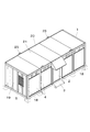
図1に示すように、ランドリー施設はコンテナ状構造の家屋1であり、それ自体で輸送可能な強度を備えている。外観は正面の中央部に出入口扉2が設けられ、出入口扉2の下方には出入口階段3が設けられ、正面の左右部にそれぞれ2枚の透明ガラス窓4が設けられ、右側面及び左側面にそれぞれ換気窓5が設けられている。
【0011】
図2に示すように、家屋1内部には洗濯機6a及び乾燥機6bを含む電気式ランドリー装置6と、受水槽とポンプとからなる給水装置7と、手洗台8とが組み込まれている。但し、乾燥機6bは、その送風ファンは電気式であるが、その熱源はガス式である。給水用ポート9、排水用ポート10、ガス用ポート11及び電気配線用ポート15は家屋1の背面下部の一箇所に集中して配置されている。
【0012】
洗濯機6a及び乾燥機6bは家屋1の背面から配管及び配線ができるスペースを確保した位置に、洗濯機6a及び乾燥機6bの前面を揃えるように一列に近接して配置されている。また、洗濯機6aと給水用ポート9、排水用ポート10及び電気配線用ポート15との間には給水管12、配水管13及び電気配線16が、それぞれ短くコンパクトに配設されている。乾燥機6bと排水用ポート10、ガス用ポート11及び電気配線用ポート15との間には配水管13、ガス管14及び電気配線16が、それぞれ短くコンパクトに配設されている。この家屋1が現場に設置されたとき各ポート9、10、11、15にそれぞれ現場の給水設備、排水設備、ガス設備及び電源を接続すれば施設の使用が可能となっている。
【0013】
なお、ガス管14にはガス給湯器(図示略)が接続されており、ガス給湯器で作られたお湯は給水管12を通って電気式ランドリー装置6に供給される。
【0014】
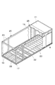
図3に示すように、電気式ランドリー装置6の振動を受けても実質的に振動せず、長距離輸送にも耐えうる強度を備えるために具体的には、家屋1は鋼製の梁と柱で構成されており、H型鋼と角形鋼板管よりなる梁を組んでなる床枠17が設けられ、該床枠17から四隅と各長辺間に2本の計8本の角形鋼管よりなる柱18が立設され、該柱18にコルゲート鋼板よりなる外板19が周設され、該柱18の上端に角形鋼板管よりなる上梁20が架設され、該上梁20に平板よりなる屋根21が載設されてなる。「実質的に振動しない」とは、ランドリー施設の利用者が不快と感じるような振動は発生しないということである。
【0015】
床枠17はH型鋼よりなる外梁22にて外枠が形成され、この外枠内は角形鋼よりなる内梁23により縦横に架設されている。さらに、図4に示すように、電気式ランドリー装置6が設置される部分には更なる補強と振動対策のためさらにH型鋼による補強梁24が架設されている。
【0016】
上梁20の各長辺にそれぞれ2本の吊り金具25が設けられており、該吊り金具25に設けられている孔にクレーンを引っかけることでランドリー施設の上吊り荷役ができるようになっている。
【0017】
家屋1の内装について、床板はコンパネの二重張りとし、さらに、電気式ランドリー装置6が設置される部分には鋼板を設けることで補強されている。
【0018】
出入口扉2側に雨水が流れ落ちないよう屋根21には後側ほど下がる100mmの片流れ勾配が設けられている。
【0019】
図5に示すように、出入口階段3は現場の形状に合わせて高さ調整ができ、出入口階段3の縁上部に設けられボルト孔を備えた階段固定部26と、外梁22とをボルトで締着することで家屋1と出入口階段3とが固定され、出入口階段3の縁下部とボルト孔を備えた階段脚部27とをボルトで締着することで地面に階段が設置される。階段固定部26と階段脚部27に備えられたボルト孔は上下に細長く形成されているためボルトの締め位置の上下を変化させることで階段固定部26は階段の高さを、階段脚部27は地面と階段との設置性を調整することができる。
【0020】
このように構成されたランドリー施設によれば、以下に示す(1)〜(6)の効果が得られる。
(1) 工場でコンテナ状構造の家屋1に電気式ランドリー装置6を組み込んだ状態で現場に輸送し、現場では給排水設備、ガス設備及び電源の接続をするだけでよいため、資材の運搬を最少限にできかつ現場での工期を短縮することができる。
(2) 前記コンテナ状構造が鋼製の梁によって強固に組み上げられているため十分な強度を備え、不快な振動が発生しない。さらに梁上に吊り金具25が設けられているため、長期間の輸送も可能になり、設置後の移設や増設も容易に行うことができる。
(3) 各ポート9、10、11、15を家屋1の背面に一箇所に集中して配置し、前記各ポートとランドリー装置との間には給水管12、配水管13、ガス管14及び電気配線16を短くコンパクトに配設することで、工場での工事を短縮でき、また、ランドリースペースが広くとることができる。
(4) 床板の一部に吸気口及び排気口を貫設して設けたため、雨水の施設内への侵入や隣地への排気漏れを防ぐことができる。
(5) 屋根21に片流れ勾配を設けたことで、出入口に雨水が流れ落ちることがなくなった。
(6) 出入口階段3の高さ調整ができるようにしたことで、現場の地形に関係なく階段の設置が容易にできる。
【0021】
なお、本発明は前記実施形態の構成に限定されず、例えば以下のように、発明の趣旨から逸脱しない範囲で適宜変更して具体化することもできる。
(1)補強梁24を床枠17の全体に渡って設ける。
(2)屋根21又は上梁20に看板を設ける。
【0022】
【発明の効果】
以上詳述したように、請求項1の発明に係るランドリー施設によれば、資材の運搬を最少限にできかつ現場での工期を短縮することができるだけでなく、強固に組み上げられて十分な強度を備えるため、利用者が不快に感じるような振動を発生せず、長期間の輸送も可能になり、設置後の移設も容易に行うことができ、さらには、床板の一部に吸気口及び排気口の両方を設けたことで、施設内への雨水侵入と、隣地への排気漏れを防ぐこともでき、また、出入口に雨水が流れ落ちることを防ぐことができ、階段の設置が現場に関係なく容易にできる。
【図面の簡単な説明】
【図1】本発明を具体化した実施形態のランドリー施設の斜視図である。
【図2】同ランドリー施設の使用状態を示す断面図である。
【図3】同ランドリー施設の構造を示す斜視図である。
【図4】同ランドリー施設のランドリー装置下における補強構造を示す斜視図である。
【図5】同ランドリー施設の出入口階段の構造を示す斜視図である。
【符号の説明】
1 家屋
2 出入口扉
3 出入口階段
4 透明ガラス窓
5 換気窓
6 電気式ランドリー装置
6a 洗濯機
6b 乾燥機
7 給水装置
8 手洗台
9 給水用ポート
10 排水用ポート
11 ガス用ポート
12 給水管
13 配水管
14 ガス管
15 電気配線用ポート
16 電気配線
17 床枠
18 柱
19 外板
20 上梁
21 屋根
22 外梁
23 内梁
24 補強梁
25 吊り金具
26 階段固定部
27 階段脚部[0001]
BACKGROUND OF THE INVENTION
The present invention relates to a laundry facility in which a laundry machine, a clothes dryer and other laundry devices are incorporated and used.
[0002]
[Prior art]
In general, laundry facilities are installed by transporting materials directly to the site, constructing the facility, and installing laundry equipment.
[0003]
[Problems to be solved by the invention]
However, when trying to build from the beginning, there was a problem that it took time and labor to complete the construction work and the laundry equipment alone, and it took a long time to complete. In addition, there was a problem that, when trying to relocate, existing buildings had to be demolished, so there was an extra cost, and when trying to add, there was a problem that the business was hindered when the construction period was prolonged.
[0004]
The object of the present invention is not only to solve the above-mentioned problems, to minimize the transportation of materials and to shorten the construction period on site, but because it is firmly assembled and has sufficient strength, the user can It does not generate unpleasant vibrations, can be transported for a long period of time, can be easily moved after installation, and has both an inlet and an outlet on part of the floorboard. Therefore, it is possible to prevent rainwater from entering the facility and leaking exhaust to the adjacent land, and rainwater does not flow down to the entrance and exit, and the height of the entrance and exit stairs can be adjusted. It is to provide a laundry facility that can be easily installed .
[0005]
[Means for Solving the Problems]
In order to achieve the above object, a laundry facility of the present invention includes a house having a container-like structure with transportable strength, and an electric laundry apparatus incorporated in the house,
The house has a floor frame made of steel beams so as not to substantially vibrate even when subjected to vibration of the laundry device, a plurality of columns erected from the floor frame, and provided around the column. Including a wall plate, an upper beam constructed on the upper end of the pillar, and a roof placed on the upper beam,
The floor frame has an outer beam made of H-shaped steel, an inner beam made of square steel vertically and horizontally in the outer beam, and a portion where the electric laundry apparatus is installed for further reinforcement and vibration countermeasures. Including a reinforced beam made of H-shaped steel,
The floorboard is double-tensioned in the panel, and the part where the electric laundry device is installed is reinforced by providing a steel plate,
Both the inlet and the outlet in a part of the floor plate is provided,
Provide a doorway in front of the house, and provide a single-flow gradient that descends toward the rear side of the roof so that rainwater does not flow down on the doorway side,
An entrance staircase is provided at the entrance,
The house and the entrance and exit stairs are fixed by fastening the stair fixing portion provided at the upper edge of the entrance and exit staircase with a vertically elongated bolt hole and the outer beam with bolts. By changing the top and bottom of the bolt tightening position in the hole, the height of the stairs is adjusted according to the site,
The stairs are installed on the ground by bolting the lower edge of the entrance and exit stairs and the stair leg portion having the elongated bolt holes on the upper and lower sides, and the upper and lower positions of the bolts tightened to the bolt holes are adjusted. By changing, the installation property of the ground and the stairs is adjusted .
Also, the laundry facility is provided between the water supply / drainage port of the house and the electric laundry apparatus, and between the electric wiring port of the house and the electric laundry apparatus. In the site installed after transportation, the facility can be used by connecting the water supply / drainage facility and the power source to the water supply / drainage port and the electrical wiring port, respectively.
[0006]
The heat source of the dryer as the electric laundry apparatus is gas, and a gas port is provided in the house, a gas pipe is provided between the dryer and the gas port of the house, and is installed after transportation. The dryer can be used by connecting an on-site gas facility to the gas port.
[0007]
Here, examples of the electric laundry apparatus include a washing machine (including a machine having a built-in dehydration function), a dryer, and the like. However, in the dryer, even if the blower fan is an electric type, the heat source is preferably a gas type (combustion gas) in terms of cost rather than the electric type.
[0009]
Various embodiments can be exemplified by combining the following (1) to (3) .
(1) A suspension bracket for transportation is provided on the upper beam.
(2) The ports for water supply and drainage are concentrated in one place of the house.
(3) A water supply device comprising a water receiving tank and a pump is provided inside the house.
[0010]
DETAILED DESCRIPTION OF THE INVENTION
Hereinafter, an embodiment of a laundry facility embodying the present invention will be described with reference to FIGS.
As shown in FIG. 1, the laundry facility is a
[0011]
As shown in FIG. 2, an
[0012]
The
[0013]
A gas water heater (not shown) is connected to the
[0014]
As shown in FIG. 3, specifically, the
[0015]
The
[0016]
Two
[0017]
About the interior of the
[0018]
The
[0019]
As shown in FIG. 5, the height of the entrance /
[0020]
According to the laundry facility configured as described above, the following effects (1) to (6) can be obtained.
(1) Since the
(2) Since the container-like structure is firmly assembled by steel beams, the container-like structure has sufficient strength, and unpleasant vibration does not occur. Furthermore, since the hanging
(3) The
(4) Since the air inlet and exhaust port are provided through a part of the floor board, it is possible to prevent rainwater from entering the facility and exhaust leakage to the adjacent ground.
(5) By providing a single-flow gradient on the
(6) Since the height of the entrance /
[0021]
In addition, this invention is not limited to the structure of the said embodiment, For example, as follows, it can also be changed and embodied suitably in the range which does not deviate from the meaning of invention.
(1) The reinforcing
(2) A signboard is provided on the
[0022]
【The invention's effect】
As described in detail above, according to the laundry facility of the first aspect of the invention, not only can the transportation of materials be minimized and the construction period on site can be shortened, but also it can be firmly assembled and has sufficient strength. Therefore, it does not generate vibrations that make the user feel uncomfortable, can be transported for a long period of time, and can be easily moved after installation. By providing both exhaust ports , it is possible to prevent rainwater intrusion into the facility and exhaust leakage to the adjacent land, and it is also possible to prevent rainwater from flowing down to the entrance and exit, and the installation of stairs is related to the site. It can be done easily.
[Brief description of the drawings]
FIG. 1 is a perspective view of a laundry facility according to an embodiment of the present invention.
FIG. 2 is a cross-sectional view showing a usage state of the laundry facility.
FIG. 3 is a perspective view showing the structure of the laundry facility.
FIG. 4 is a perspective view showing a reinforcing structure under a laundry apparatus in the laundry facility.
FIG. 5 is a perspective view showing the structure of the entrance and exit stairs of the laundry facility.
[Explanation of symbols]
DESCRIPTION OF
Claims (1)
前記家屋は、前記ランドリー装置の振動を受けても実質的に振動しないように鋼製の梁を組んでなる床枠と、該床枠から立設した複数の柱と、該柱に周設した壁板と、該柱の上端に架設した上梁と、該上梁に載設した屋根とを含み、
前記床枠は、H型鋼よりなる外梁と、前記外梁内に縦横に架設された角形鋼よりなる内梁と、前記電気式ランドリー装置が設置される部分に更なる補強と振動対策のため架設されたH型鋼よりなる補強梁とを含み、
床板は、コンパネの二重張りとし、さらに前記電気式ランドリー装置が設置される部分は鋼板を設けることで補強されており、
前記床板の一部に吸気口及び排気口の両方を設け、
前記家屋の正面に出入口を設け、該出入口側に雨水が流れ落ちないよう前記屋根に後側ほど下がる片流れ勾配を設け、
前記出入口に出入口階段を設け、
前記出入口階段の縁上部に設けられ上下に細長いボルト孔を備えた階段固定部と、前記外梁とをボルトで締着することで、前記家屋と前記出入口階段とが固定されるとともに、該ボルト孔へのボルトの締め位置の上下を変化させることで、現場に合わせて階段の高さが調整され、
前記出入口階段の縁下部と上下に細長いボルト孔を備えた階段脚部とをボルトで締着することで、地面に階段が設置されるとともに、該該ボルト孔へのボルトの締め位置の上下を変化させることで、地面と階段との設置性が調整されることを特徴とするランドリー施設。A house having a container-like structure with transportable strength, and an electric laundry device incorporated in the house,
The house has a floor frame made of steel beams so as not to substantially vibrate even when subjected to vibration of the laundry device, a plurality of columns erected from the floor frame, and provided around the column. Including a wall plate, an upper beam constructed on the upper end of the pillar, and a roof placed on the upper beam,
The floor frame has an outer beam made of H-shaped steel, an inner beam made of square steel vertically and horizontally in the outer beam, and a portion where the electric laundry apparatus is installed for further reinforcement and vibration countermeasures. Including a reinforced beam made of H-shaped steel,
The floorboard is double-tensioned in the panel, and the part where the electric laundry device is installed is reinforced by providing a steel plate,
Both the inlet and the outlet in a part of the floor plate is provided,
Provide a doorway in front of the house, and provide a single-flow gradient that descends toward the rear side of the roof so that rainwater does not flow down on the doorway side,
An entrance staircase is provided at the entrance,
The house and the entrance and exit stairs are fixed by fastening the stair fixing portion provided at the upper edge of the entrance and exit staircase with a vertically elongated bolt hole and the outer beam with bolts. By changing the top and bottom of the bolt tightening position in the hole, the height of the stairs is adjusted according to the site,
The stairs are installed on the ground by bolting the lower edge of the entrance and exit stairs and the stair leg portion having the elongated bolt holes on the upper and lower sides, and the upper and lower positions of the bolts tightened to the bolt holes are adjusted. Laundry facilities characterized by the ability to change the installation of the ground and stairs .
Priority Applications (1)
| Application Number | Priority Date | Filing Date | Title |
|---|---|---|---|
| JP2000173985A JP4615675B2 (en) | 2000-06-09 | 2000-06-09 | Laundry facilities |
Applications Claiming Priority (1)
| Application Number | Priority Date | Filing Date | Title |
|---|---|---|---|
| JP2000173985A JP4615675B2 (en) | 2000-06-09 | 2000-06-09 | Laundry facilities |
Publications (3)
| Publication Number | Publication Date |
|---|---|
| JP2001349073A JP2001349073A (en) | 2001-12-21 |
| JP2001349073A5 JP2001349073A5 (en) | 2006-11-30 |
| JP4615675B2 true JP4615675B2 (en) | 2011-01-19 |
Family
ID=18676112
Family Applications (1)
| Application Number | Title | Priority Date | Filing Date |
|---|---|---|---|
| JP2000173985A Expired - Lifetime JP4615675B2 (en) | 2000-06-09 | 2000-06-09 | Laundry facilities |
Country Status (1)
| Country | Link |
|---|---|
| JP (1) | JP4615675B2 (en) |
Families Citing this family (1)
| Publication number | Priority date | Publication date | Assignee | Title |
|---|---|---|---|---|
| JP6574749B2 (en) * | 2016-11-09 | 2019-09-11 | 株式会社リンク・ソリューション | Trailer house |
-
2000
- 2000-06-09 JP JP2000173985A patent/JP4615675B2/en not_active Expired - Lifetime
Also Published As
| Publication number | Publication date |
|---|---|
| JP2001349073A (en) | 2001-12-21 |
Similar Documents
| Publication | Publication Date | Title |
|---|---|---|
| CN101654929B (en) | Combined type house and assembly method thereof | |
| US4171596A (en) | Prefabricated room structure for facilities in general such as toilets, baths, kitchens and the like | |
| CN101654927B (en) | Main structure of combined type house and assembly method thereof | |
| JP2004507633A (en) | Modular building | |
| JPH10234493A (en) | Kitchen structure | |
| JP4615675B2 (en) | Laundry facilities | |
| JP3208435U (en) | Dry box facility | |
| KR101940456B1 (en) | Noise protection panel for gangue foam | |
| JP6399440B2 (en) | Building unit and building | |
| AU2011201797B2 (en) | Prefabricated Room Assembly | |
| JP3484232B2 (en) | Unit building | |
| KR200261644Y1 (en) | A light weight-complex panel for prefabricated bath room | |
| JP2009215750A (en) | Chamber unit reinforcing structure of wooden house | |
| JP2009097255A (en) | Apartment house | |
| WO2016006207A1 (en) | Building and building unit | |
| CN105863116A (en) | Double-layer square steel tube sound insulation wall structure and mounting method thereof | |
| JP3281095B2 (en) | Aluminum frame structure | |
| JP2001130692A5 (en) | ||
| JP3062810B2 (en) | Assembling method of plumbing unit in building and plumbing unit | |
| KR100399003B1 (en) | Bathroom integrally Constructed by Panels | |
| JP2003129571A (en) | Unit room | |
| JP3556107B2 (en) | Integrated toilet unit structure | |
| CN110230355A (en) | A kind of outdoor moving building | |
| JP2022014825A (en) | Staircase unit | |
| JP6484900B2 (en) | Building unit and building |
Legal Events
| Date | Code | Title | Description |
|---|---|---|---|
| A521 | Written amendment |
Free format text: JAPANESE INTERMEDIATE CODE: A523 Effective date: 20061004 |
|
| A621 | Written request for application examination |
Free format text: JAPANESE INTERMEDIATE CODE: A621 Effective date: 20061004 |
|
| A977 | Report on retrieval |
Free format text: JAPANESE INTERMEDIATE CODE: A971007 Effective date: 20080117 |
|
| A131 | Notification of reasons for refusal |
Free format text: JAPANESE INTERMEDIATE CODE: A131 Effective date: 20080129 |
|
| A131 | Notification of reasons for refusal |
Free format text: JAPANESE INTERMEDIATE CODE: A131 Effective date: 20080311 |
|
| A521 | Written amendment |
Free format text: JAPANESE INTERMEDIATE CODE: A523 Effective date: 20080508 |
|
| A131 | Notification of reasons for refusal |
Free format text: JAPANESE INTERMEDIATE CODE: A131 Effective date: 20081209 |
|
| A521 | Written amendment |
Free format text: JAPANESE INTERMEDIATE CODE: A523 Effective date: 20090127 |
|
| A02 | Decision of refusal |
Free format text: JAPANESE INTERMEDIATE CODE: A02 Effective date: 20090602 |
|
| A521 | Written amendment |
Free format text: JAPANESE INTERMEDIATE CODE: A821 Effective date: 20090831 |
|
| A01 | Written decision to grant a patent or to grant a registration (utility model) |
Free format text: JAPANESE INTERMEDIATE CODE: A01 |
|
| A61 | First payment of annual fees (during grant procedure) |
Free format text: JAPANESE INTERMEDIATE CODE: A61 Effective date: 20101021 |
|
| R150 | Certificate of patent or registration of utility model |
Ref document number: 4615675 Country of ref document: JP Free format text: JAPANESE INTERMEDIATE CODE: R150 Free format text: JAPANESE INTERMEDIATE CODE: R150 |
|
| FPAY | Renewal fee payment (event date is renewal date of database) |
Free format text: PAYMENT UNTIL: 20131029 Year of fee payment: 3 |
|
| R250 | Receipt of annual fees |
Free format text: JAPANESE INTERMEDIATE CODE: R250 |
|
| R250 | Receipt of annual fees |
Free format text: JAPANESE INTERMEDIATE CODE: R250 |
|
| R250 | Receipt of annual fees |
Free format text: JAPANESE INTERMEDIATE CODE: R250 |
|
| EXPY | Cancellation because of completion of term |