JP4613615B2 - Manufacturing method of heat exchanger tank - Google Patents
Manufacturing method of heat exchanger tank Download PDFInfo
- Publication number
- JP4613615B2 JP4613615B2 JP2004558451A JP2004558451A JP4613615B2 JP 4613615 B2 JP4613615 B2 JP 4613615B2 JP 2004558451 A JP2004558451 A JP 2004558451A JP 2004558451 A JP2004558451 A JP 2004558451A JP 4613615 B2 JP4613615 B2 JP 4613615B2
- Authority
- JP
- Japan
- Prior art keywords
- tank
- punch
- partition
- partition portion
- die
- Prior art date
- Legal status (The legal status is an assumption and is not a legal conclusion. Google has not performed a legal analysis and makes no representation as to the accuracy of the status listed.)
- Expired - Lifetime
Links
- 238000004519 manufacturing process Methods 0.000 title claims description 16
- 238000005192 partition Methods 0.000 claims description 75
- 238000004891 communication Methods 0.000 claims description 23
- 230000002093 peripheral effect Effects 0.000 claims description 16
- 238000000034 method Methods 0.000 claims description 15
- 238000001125 extrusion Methods 0.000 claims description 12
- 239000000463 material Substances 0.000 claims description 11
- 238000009423 ventilation Methods 0.000 claims description 11
- 238000000638 solvent extraction Methods 0.000 claims 1
- 238000003780 insertion Methods 0.000 description 8
- 230000037431 insertion Effects 0.000 description 8
- 238000005219 brazing Methods 0.000 description 4
- 230000015572 biosynthetic process Effects 0.000 description 3
- 238000005553 drilling Methods 0.000 description 3
- 238000003475 lamination Methods 0.000 description 3
- 229910052751 metal Inorganic materials 0.000 description 3
- 239000002184 metal Substances 0.000 description 3
- 238000005452 bending Methods 0.000 description 2
- 238000005520 cutting process Methods 0.000 description 2
- 238000010586 diagram Methods 0.000 description 2
- 238000003825 pressing Methods 0.000 description 2
- 239000003507 refrigerant Substances 0.000 description 2
- 229910000838 Al alloy Inorganic materials 0.000 description 1
- 229910052782 aluminium Inorganic materials 0.000 description 1
- XAGFODPZIPBFFR-UHFFFAOYSA-N aluminium Chemical compound [Al] XAGFODPZIPBFFR-UHFFFAOYSA-N 0.000 description 1
- 238000009826 distribution Methods 0.000 description 1
- 239000000945 filler Substances 0.000 description 1
- 238000005057 refrigeration Methods 0.000 description 1
- 238000011144 upstream manufacturing Methods 0.000 description 1
Images


Classifications
-
- F—MECHANICAL ENGINEERING; LIGHTING; HEATING; WEAPONS; BLASTING
- F28—HEAT EXCHANGE IN GENERAL
- F28D—HEAT-EXCHANGE APPARATUS, NOT PROVIDED FOR IN ANOTHER SUBCLASS, IN WHICH THE HEAT-EXCHANGE MEDIA DO NOT COME INTO DIRECT CONTACT
- F28D1/00—Heat-exchange apparatus having stationary conduit assemblies for one heat-exchange medium only, the media being in contact with different sides of the conduit wall, in which the other heat-exchange medium is a large body of fluid, e.g. domestic or motor car radiators
- F28D1/02—Heat-exchange apparatus having stationary conduit assemblies for one heat-exchange medium only, the media being in contact with different sides of the conduit wall, in which the other heat-exchange medium is a large body of fluid, e.g. domestic or motor car radiators with heat-exchange conduits immersed in the body of fluid
- F28D1/04—Heat-exchange apparatus having stationary conduit assemblies for one heat-exchange medium only, the media being in contact with different sides of the conduit wall, in which the other heat-exchange medium is a large body of fluid, e.g. domestic or motor car radiators with heat-exchange conduits immersed in the body of fluid with tubular conduits
- F28D1/053—Heat-exchange apparatus having stationary conduit assemblies for one heat-exchange medium only, the media being in contact with different sides of the conduit wall, in which the other heat-exchange medium is a large body of fluid, e.g. domestic or motor car radiators with heat-exchange conduits immersed in the body of fluid with tubular conduits the conduits being straight
- F28D1/0535—Heat-exchange apparatus having stationary conduit assemblies for one heat-exchange medium only, the media being in contact with different sides of the conduit wall, in which the other heat-exchange medium is a large body of fluid, e.g. domestic or motor car radiators with heat-exchange conduits immersed in the body of fluid with tubular conduits the conduits being straight the conduits having a non-circular cross-section
- F28D1/05366—Assemblies of conduits connected to common headers, e.g. core type radiators
- F28D1/05391—Assemblies of conduits connected to common headers, e.g. core type radiators with multiple rows of conduits or with multi-channel conduits combined with a particular flow pattern, e.g. multi-row multi-stage radiators
-
- F—MECHANICAL ENGINEERING; LIGHTING; HEATING; WEAPONS; BLASTING
- F28—HEAT EXCHANGE IN GENERAL
- F28F—DETAILS OF HEAT-EXCHANGE AND HEAT-TRANSFER APPARATUS, OF GENERAL APPLICATION
- F28F9/00—Casings; Header boxes; Auxiliary supports for elements; Auxiliary members within casings
- F28F9/02—Header boxes; End plates
- F28F9/0202—Header boxes having their inner space divided by partitions
- F28F9/0204—Header boxes having their inner space divided by partitions for elongated header box, e.g. with transversal and longitudinal partitions
- F28F9/0214—Header boxes having their inner space divided by partitions for elongated header box, e.g. with transversal and longitudinal partitions having only longitudinal partitions
Landscapes
- Engineering & Computer Science (AREA)
- Physics & Mathematics (AREA)
- Thermal Sciences (AREA)
- Mechanical Engineering (AREA)
- General Engineering & Computer Science (AREA)
- Heat-Exchange Devices With Radiators And Conduit Assemblies (AREA)
Description
この発明は、熱交換チューブとは別体の熱交換器用タンクの構成、特に仕切り部の構成に関するものである。 The present invention relates to a configuration of a heat exchanger tank separate from a heat exchange tube, particularly to a configuration of a partition portion.
熱交換チューブと別体の熱交換器用タンクを有し、この熱交換器用タンクは、その内部が少なくとも長手方向に沿って延びる仕切り部により仕切られて、複数の分室が画成されており、当該仕切り部はタンク部と一体に構成された冷媒蒸発器に対し、前記仕切り部にバイパス孔を複数設けて、このバイパス孔により通風方向に沿って並列した分室間における冷媒のバイパスを図る構成については、既に公知である(例えば、特開平11−287587号公報〔特に、段落番号「0021」から「0024」及びその図1、図13、図14〕を参照)。そして、この公報には、バイパス孔が、仕切り部を構成する金属(アルミニウム等)の薄板に例えばプレス加工で複数、同時に打ち抜き加工されて矩形状に形成される旨が開示されている。 A heat exchanger tank and a separate heat exchanger tank, the inside of the heat exchanger tank being partitioned by a partition portion extending at least along the longitudinal direction to define a plurality of compartments; For the refrigerant evaporator configured integrally with the tank unit, the partition unit is provided with a plurality of bypass holes in the partition unit, and the bypass unit bypasses the refrigerant between the parallel chambers along the ventilation direction. Already known (see, for example, Japanese Patent Application Laid-Open No. 11-287487 (particularly, paragraph numbers “0021” to “0024” and FIGS. 1, 13, and 14 thereof). This publication discloses that a plurality of bypass holes are formed in a rectangular shape by stamping a plurality of metal thin plates (such as aluminum) constituting the partition portion, for example, by pressing.
しかしながら、上記の仕切り部にバイパス孔を形成する製造方法は、1枚の薄板をロールホーミングで複数段折り曲げて熱交換器用タンクを形成することを前提としたものである。すなわち、薄板に対し折り曲げ前の平坦時に所定の間隔をおいて複数の孔を穿つと共に、一方の孔にはその周縁からバーリングを立設させておき、ロールホーミングにより薄板を折り曲げて仕切り部を構成する過程において、一方の孔の周縁に形成されたバーリングを他方の孔に挿入することで、仕切り部を連通するバイパス孔を形成する。 However, the manufacturing method for forming a bypass hole in the partition part is based on the premise that a heat exchanger tank is formed by bending a thin sheet in a plurality of stages by roll homing. That is, a plurality of holes are formed at a predetermined interval when flat on a thin plate before being bent, and a burring is erected from the periphery of one of the holes, and the thin plate is bent by roll homing to form a partition portion. In the process of doing this, a bypass hole communicating with the partition portion is formed by inserting a burring formed at the periphery of one hole into the other hole.
このため、押出し成形により熱交換器用タンクを製造する場合には、上記した蒸発器の製造方法をそのまま用いることはできない。 For this reason, when manufacturing the tank for heat exchangers by extrusion molding, the manufacturing method of an evaporator mentioned above cannot be used as it is.
そこで、この発明は、押出し成形で製造される熱交換器用タンクの仕切り部に対し、4パスの熱交換器に用いるために、通風方向で隣り合う画室間における熱交換媒体の移動を可能にし、また、そのために仕切り部を最適な肉厚とした熱交換器用タンクを提供することを目的とする。 Therefore, the present invention enables movement of a heat exchange medium between compartments adjacent to each other in the ventilation direction for use in a four-pass heat exchanger with respect to a partition portion of a heat exchanger tank manufactured by extrusion molding. Moreover, it aims at providing the tank for heat exchangers which made the partition part the optimal thickness for that purpose.
この発明に係る熱交換器用タンクの製造方法は、外周部とこの外周部に囲まれた内部空間を仕切る仕切り部とが押し出し成形により一体に製造されると共に、前記仕切り部により前記内部空間が通風方向に並列した複数の画室に画成される熱交換器用タンクの製造方法であって、前記仕切り部の肉厚が、0.4mm以上、1.65mm以下となり、前記タンク外周部の肉厚が、前記仕切り部の肉厚と等しいか、当該仕切り部の肉厚よりも厚くなるように前記押し出し成形を行ってタンク素材を製造する工程と、前記仕切り部に前記画室間を連通する連通路を形成する工程とを有し、前記連通路を形成する工程は、前記タンクの長手方向の端部から所定寸法離れた内側に位置するように且つ切り欠き状ではなく孔状の連通路となるように、前記タンクの画室の長手方向の端部の開口部から前記仕切り部を挟むようにパンチとダイスとを挿入して前記仕切り部に穿孔加工を行う工程であることを特徴としている(請求項1)。そして、前記仕切り部に穿孔加工を行う工程は、通孔が形成された前記パンチと、このパンチの通孔に挿通可能な外形を有する前記ダイスと、前記ダイスを前記パンチ側に移動するための可動部とを備えた金型を利用して行うものであって、前記パンチと前記可動部とを前記画室の長手方向端部の開口部からそれぞれ挿入した後、前記パンチを前記仕切り部の面に沿わせて固定した状態に置き、前記可動部を動かして前記ダイスの先端を前記パンチ側に当該パンチの通孔に挿入するまで移動してプレス加工を行うことを特徴としている(請求項2)。 In the method for manufacturing a heat exchanger tank according to the present invention, an outer peripheral portion and a partition portion that partitions the inner space surrounded by the outer peripheral portion are integrally manufactured by extrusion molding, and the inner space is ventilated by the partition portion. A method of manufacturing a heat exchanger tank defined in a plurality of compartments arranged in parallel in a direction, wherein a thickness of the partition portion is 0.4 mm or more and 1.65 mm or less, and a thickness of the outer peripheral portion of the tank is A step of manufacturing the tank material by performing the extrusion molding so as to be equal to or thicker than the thickness of the partition part, and a communication path communicating between the compartments to the partition part. The step of forming the communication path is a hole-shaped communication path that is located not on the inside of the notch but on the inside at a predetermined distance from the longitudinal end of the tank. And said It is characterized in that the opening of the longitudinal ends of the compartment of the tank by inserting the punch and the die so as to sandwich the partition portion is a step for drilling the partition portion (claim 1). The step of perforating the partition portion includes the punch in which the through hole is formed, the die having an outer shape that can be inserted into the through hole of the punch, and the die for moving to the punch side. The mold is provided with a movable portion, and the punch and the movable portion are inserted through the opening at the longitudinal end of the compartment, and then the punch is placed on the surface of the partition portion. And moving the movable part to move the tip of the die to the punch side until it is inserted into the through hole of the punch, and press working is performed ( Claim 2). ).
これにより、押出し成形で仕切り部も外周部と一体的に形成される熱交換器用タンクについても、連通路を介して複数の画室間を熱交換媒体が移動することが可能となる。
ここで、仕切り部に対し一辺が開放された切り欠きを形成し、画室の開口を閉塞するための蓋体部とで連通路を形成することも考えられるが、蓋体の未組み付け時においてタンクの長手方向に沿った側のうち連通路を有する側の部位は、仕切り部の切り欠きにより強度が弱くなるという不具合を生ずることが考えられる。このため、連通路は、後過程で当該仕切り部に対し切り欠き状ではなく孔状の連通路を形成することが好ましい。このような構成においては、タンクの強度を相対的に高めることが可能となる。
また、前記連通路は、タンク内での熱交換媒体の分配を考慮すると、タンクの長手方向の端部から所定寸法離れた内側に孔状の連通路を前記仕切り部に穿孔加工することが好ましい。
As a result, the heat exchange medium can be moved between the plurality of compartments via the communication path in the heat exchanger tank that is integrally formed with the partition portion and the outer peripheral portion by extrusion molding.
Here, it is conceivable to form a notch with one side open with respect to the partition part, and to form a communication path with the lid part for closing the opening of the compartment, but when the lid is not assembled, the tank It is conceivable that a portion of the side along the longitudinal direction having the communication path has a problem that the strength is weakened due to the notch of the partition portion. For this reason, it is preferable that a communicating path forms not a notch shape but a hole-shaped communicating path with respect to the said partition part in a post process. In such a configuration, the strength of the tank can be relatively increased.
Further, in consideration of the distribution of the heat exchange medium in the tank, it is preferable that the communication path is formed by drilling a hole-shaped communication path inside the partition portion at a predetermined distance from the end in the longitudinal direction of the tank. .
ところで、押出し成形により製造されるタンクの仕切り部に連通路を後過程により形成する方法として、通風方向に沿って並列した画室に対し長手方向端に開口した開口部の一方からそれぞれパンチ・ダイスを挿入し、穿孔加工を行うことにより連通路を形成することが考えられるがパンチ・ダイスの支点・力点はプレスの作動方向同軸上にないので、金型の疲労強度に難があるという不具合を有する。
この不具合は、熱交換器用タンクの仕切り部の薄肉化により解消することが可能であるが、今度は仕切りプレートの組付け時や市場仕様環境での熱交換器用タンク仕切り部の変形が懸念される。
そこで、この発明に係る熱交換器用タンクの仕切り部は、その肉厚を0.4mm以上、1.65mm以下に設定することが望ましい。この場合、タンク外周部の肉厚は、前記仕切り部の肉厚と等しいが、当該仕切り部の肉厚よりも厚くするとよい。
これにより、当該熱交換器用タンクについて、通風方向に沿って並列した画室に対し長手方向端に開口した開口部の一方からそれぞれパンチ・ダイスを挿入して穿孔加工を行うにあたり、仕切り部の肉厚を0.4mm以上、1.65mm以下としたことで、仕切り部が従来の仕切り部よりも相対的に薄肉化して、パンチ・ダイスの支点・力点が作動方向同軸上になくても、予定される金型の使用回数が確保されるように金型の疲労強度を大きくすることが可能になると共に、その薄肉化も仕切り部の変形防止に必要な強度を担保できることから、タンクのスリットに仕切りプレートを挿入し取り付ける際や市場仕様環境において仕切り部が変形してしまうという不具合も回避することができる。
By the way, as a method of forming a communication path in a partition part of a tank manufactured by extrusion molding in a later process, punch dies are respectively provided from one of openings opened at the longitudinal end with respect to compartments arranged in parallel along the ventilation direction. It is conceivable to form a communication path by inserting and drilling, but the fulcrum / power point of the punch / die is not on the same axis as the operation direction of the press, so there is a problem that the fatigue strength of the mold is difficult. .
This problem can be resolved by thinning the partition of the heat exchanger tank, but this time there is a concern that the partition of the heat exchanger tank may be deformed when the partition plate is assembled or in a market specification environment. .
Therefore, it is desirable to set the wall thickness of the partition portion of the heat exchanger tank according to the present invention to 0.4 mm or more and 1.65 mm or less. In this case, the thickness of the outer peripheral portion of the tank is equal to the thickness of the partition portion, but is preferably thicker than the thickness of the partition portion.
Thus, for the heat exchanger tank, the thickness of the partition portion is determined when the punch and die are inserted from one of the openings opened at the longitudinal ends of the compartments arranged in parallel along the ventilation direction. Is set to 0.4 mm or more and 1.65 mm or less, so that the partition part becomes thinner than the conventional partition part, and the fulcrum / power point of the punch and die is not coaxial with the operation direction. It is possible to increase the fatigue strength of the mold so that the number of times the mold can be used is secured, and the thinning of the mold can ensure the strength necessary to prevent deformation of the partition. It is possible to avoid the problem that the partition portion is deformed when the plate is inserted and attached or in a market specification environment.
以上述べたように、本発明に係る熱交換器用タンクの製造方法によれば、押出し成形で仕切り部も外周部と一体的に形成される熱交換器用タンクについても、仕切り部に連通路を形成することで画室間の連通が可能となり、また、後過程で当該仕切り部に対し切り欠き状ではなく孔状の連通路を形成することで、タンクの強度を相対的に高めることが可能となる。 As described above, according to the method for manufacturing a heat exchanger tank according to the present invention, a communication path is formed in the partition portion even for the heat exchanger tank formed integrally with the outer peripheral portion by extrusion molding. By doing so, communication between the compartments becomes possible, and it is possible to relatively increase the strength of the tank by forming a hole-like communication path instead of a notch shape in the partition part in the subsequent process. .
また、本発明に係る熱交換器用タンクの製造方法によれば、仕切り部は、その肉厚を0.4mm以上、1.65mm以下の範囲としたことにより、従来の仕切り部よりも相対的に薄肉化して、支点・力点が作動方向同軸上にないパンチ・ダイスを用いて連通路を形成する場合であっても、予定される金型の使用回数が確保されるように金型の疲労強度を大きくすることが可能になると共に、その薄肉化も仕切り部の変形防止に必要な強度を保証した範囲内であるので、タンクの外周部に形成されたスリットに仕切りプレートを挿入して取り付ける際や市場仕様環境において変形するという不具合を回避することもできる。 Moreover, according to the manufacturing method of the tank for heat exchangers according to the present invention, the partition portion has a thickness in the range of 0.4 mm or more and 1.65 mm or less, so that it is relatively more than the conventional partition portion. Fatigue strength of the mold so that the expected number of molds can be used even when the communication path is formed using a punch and die whose fulcrum and force points are not on the same axis in the operating direction. Since it is within the range that guarantees the strength required to prevent deformation of the partition, the partition plate is inserted into the slit formed in the outer periphery of the tank and attached. It is also possible to avoid the problem of deformation in a market specification environment.
以下、この発明の実施の形態を図面により説明する。 Embodiments of the present invention will be described below with reference to the drawings.
図1に示される熱交換器1は、例えば車両用空調装置の冷凍サイクルの一部を構成するエバポレータとして用いられている。この熱交換器1は、炉中ろう付け方法により製造されており、対をなすタンク2、3と、このタンク2、3を連通する複数の熱交換チューブ4と、この熱交換チューブ4間に挿入接合されたコルゲート状のアウターフィン5と、熱交換チューブ4の積層方向端に配されるサイドプレート6と、熱交換媒体の出入口部7、8を備えたコネクタ9が取り付けられるサイドタンク10とを有して構成されている。コネクタ9は、図示しない膨張弁と接続される。そして、この熱交換器1は、図示しない膨張弁から送られる熱交換媒体を、サイドタンク10を介して流入させ、熱交換チューブ4によってタンク2、3間を移動させ、その過程においてアウターフィン5間を通過する空気と熱交換させ、最終的にサイドタンク10を介して送出されるようにしている。
A heat exchanger 1 shown in FIG. 1 is used as an evaporator constituting a part of a refrigeration cycle of a vehicle air conditioner, for example. The heat exchanger 1 is manufactured by an in-furnace brazing method, and a pair of
このうち、熱交換チューブ4は、図3(a)に示される様に、タンク2、3に挿入される両端が開口され、熱交換媒体の流路14が内部に形成された扁平管13にインナーフィン15を収納して構成されている。この実施形態では、熱交換チューブ4は、ロールホーミングにより一枚の扁平管素材を折り曲げることで形成されている。
Among these, as shown in FIG. 3 (a), the
タンク2、3は、前述のごとく、所定の間隔で対向するように配設されているもので、押出し成形により形成されており、そのため、表面にろう材層を有せず、例えばA3000系のアルミニウム合金が用いられている。
As described above, the
このうち、タンク2について図2(a)を用いて説明すると、タンク2は、熱交換チューブ4を挿入させるチューブ挿入孔17が形成されたもので、その長手方向両端に開口部が形成されているが、この開口部はキャップ19により閉塞されている。そして、タンク2は、熱交換チューブ4の積層方向(タンク2の長手方向)に沿って延びる仕切り部20が外周部18と一体に形成されており、これにより、タンク2内は、図3(b)に示される様に、通風方向に並列した画室21と画室22とが画成されている。
Of these, the
これに対し、タンク3は、図2(b)に示すように、熱交換チューブ4を挿入させるチューブ挿入孔17が形成されたもので、その長手方向両端の開口部は、キャップ19により閉塞されている点、熱交換チューブ4の積層方向(タンク3の長手方向)に沿って延びる仕切り部20が一体に形成されており、これにより、タンク3内は、図3(b)に示される様に、通風方向に並列した画室21と画室22とが画成されている点では、タンク2と略同様の構成をなしている。一方で、タンク3の画室21、画室22は、タンク2とは異なり、スリット29から挿入された仕切りプレート28により通風方向の途中が仕切られて、分室21a、21b又は22a、22bに分かれている。そして、分室21bと分室22bとは、熱交換媒体のフローを4パスとするために、連通路16により連通している。
On the other hand, as shown in FIG. 2B, the
そして、タンク3は、積層方向の終端に位置する熱交換チューブ4よりも積層方向外側に突出した突出部3aを有している。この突出部3aは、外周部18がそのまま延出して構成され、その内部も仕切り部20がキャップ19の内側面に接するまで延出している。これに伴い、突出部3a内は、タンク3の前述した画室21、22が連続した状態で画成されている。突出部3aの画室21、22は、熱交換媒体の最上流側又は最下流側を構成するもので、図2(b)に示される様に、下記するサイドタンク10の流入側通路25、流出側通路26と突出部3aに形成された開口部23、24を介して連通している。
And the
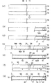
次に、熱交換器1の製造方法の一部について、タンク3を代表して、図4を用いて説明する。まず、図4(a)に示す様に、例えば長手方向寸法が長尺(例えば5m)となるように押出し成形により形成してストックしておいた複数のタンク素材Mから任意のタンク素材Mを抽出して製造ラインに乗せる。 Next, a part of the manufacturing method of the heat exchanger 1 will be described with reference to FIG. First, as shown in FIG. 4A, for example, an arbitrary tank material M is formed from a plurality of tank materials M formed and stocked by extrusion molding so that the longitudinal dimension is long (for example, 5 m). Extract and place on production line.
そして、図4(b)に示す様に、タンク素材Mの一方側の先端部位において仕切り部20に連通路16を穿った後、図4(c)に示す様に、タンク素材Mの面18Aに対し所定の範囲にわたってチューブ挿入孔17を形成する。
Then, as shown in FIG. 4B, the
更に、図4(d)に示す様に、例えば丸ノコ状のツール等で、所望の長手方向寸法となるようにタンク素材Mを切断すると共に、面18A、18B、18D又は面18A、18C(図示しないが面18Bと対峙して存する)、18Dにまたがるスリット29、29を形成し、これらの切断部位を洗浄しバリの除去等の処理を行う。これにより、タンク3の形が完成する。連通路16の形成、チューブ挿入孔17の形成及びスリット29、29の形成等の工程は、タンク素材Mが短くなるまで繰り返して行われる。
Further, as shown in FIG. 4D, the tank material M is cut to have a desired longitudinal dimension with, for example, a circular saw-shaped tool, and the
そして、図4(e)に示す様に、この完成したタンク3に対しスリット29から仕切りプレート28を画室21又は22内に装着する。最後に、図4(f)に示す様に、ろう材シート30をタンク3のチューブ挿入孔形成面18Aに貼り付けた後、図4(g)に示す様に、タンク3の長手方向両側に開口した開口部をキャップ19で閉塞することでタンク3に対する組付け工程も終了する。
Then, as shown in FIG. 4 (e), the
タンク2は、前述のように、連通路16がなく、スリット29、29を形成して当該スリット29から仕切りプレート28を画室21又は22内に装着する必要がないことから、図4(a)、図4(c)を経て、図4(d)の代わりにツールでタンク素材Mを切断する工程が入り、しかる後に、図4(f)に示す様に、ろう材シート30をタンク2のチューブ挿入孔形成面18Aに貼り付けた後、図4(g)に示す様に、タンク2の長手方向両側に開口した開口部をキャップ19で閉塞するという工程を経る。
As described above, the
最後に、タンク2のチューブ挿入孔17とタンク3のチューブ挿入孔17とに熱交換チューブ4の長手方向両端部位を挿入するなどして熱交換器1を組付けた後、この熱交換器1を炉中ろう付けすることにより、熱交換器1の製造が完了する。尚、熱交換器1の組付け及び炉中ろう付けの方法は公知のものであるから特に図示して説明しない
Finally, after the heat exchanger 1 is assembled by inserting both longitudinal ends of the
ところで、タンク3を押出し成形で製造するにあたって、外周部18が成形されると同時に仕切り部20がこの外周部18と一体成形されるが、図5に示される様に、この実施形態では、仕切り部20は、その肉厚T1が、1.0mmであり、外周部18の肉厚は、通風方向に延びる面の肉厚T2が1.5mm、通風方向と交差する方向に延びる面の肉厚T3が1.0mmとなっている。即ち、外周部18の肉厚T2、T3は、仕切り部20の肉厚T1と等しいかそれ以上の寸法となっている。尚、仕切り部20の肉厚T1は、上記した寸法1.0mmに限定されず、0.4mm以上1.65mm以下の範囲であれば良い。
By the way, when the
そして、図4(b)で示された仕切り部20に連通路16を形成する工程は、例えば、図5に示される様な、通孔34aが形成されたパンチ34と、パンチ34の通孔34aに挿通可能な外形を有するダイス35と、ダイス35をパンチ34側に移動するための可動部36とを備えた金型33を利用して行う。すなわち、パンチ34と可動部36とを画室21、22の長手方向端部の開口部からそれぞれ挿入した後、第6図に示される様に、パンチ34を仕切り部20の面に沿わせて固定した状態に置き、可動部36を動かしてダイス35の先端をパンチ34側に当該パンチ34の通孔34aに挿通するまで移動して、プレス加工を行うことによって、仕切り部20に連通路16となる矩形状の貫通孔を穿つ。
The step of forming the
この場合に、パンチ34・ダイス35の支点・力点はプレスの作動方向同軸上にないが、仕切り部20の肉厚T1を1.65mm以下として、従来の仕切り部の肉厚より相対的に薄肉化することで、金型33に与える金属疲労は抑制される。
In this case, the fulcrum and force point of the
即ち、金型の寿命は10万回ほどの使用に耐え得ることができれば実使用において支障はないので、プレス型やポンチなどで極一般的に用いられるSKH51の金型材質を利用する場合には、図7に示されるように、10万回の繰り返し使用に耐えうるプレスの許容限界応力が約850N/mm2であること、また、このような応力で加工可能な仕切り部の厚みは、図8に示されるように、1.65mm以下であることから、10万回の繰り返し使用を満足する板厚の上限を1.65mmとしている。これに対して、前述した図4(e)に示す様にタンク3のスリット29に仕切りプレート28を装着するにあたり、仕切りプレート28の先端部が仕切り部20に突当する際の力、また、市場での仕様環境で仕切り部20にかかる力に対しては、仕切り部20の肉厚の下限を0.4mmに留めることにより必要な強度が担保され、仕切り部20が変形しないことも判明している。
In other words, if the life of the mold can withstand about 100,000 times of use, there will be no problem in actual use. Therefore, when using the SKH51 mold material, which is generally used for press dies and punches, etc. 7, the allowable limit stress of the press that can withstand repeated use 100,000 times is about 850 N /
Claims (2)
前記仕切り部の肉厚が、0.4mm以上、1.65mm以下となり、前記タンク外周部の肉厚が、前記仕切り部の肉厚と等しいか、当該仕切り部の肉厚よりも厚くなるように前記押し出し成形を行ってタンク素材を製造する工程と、前記仕切り部に前記画室間を連通する連通路を形成する工程とを有し、
前記連通路を形成する工程は、前記タンクの長手方向の端部から所定寸法離れた内側に位置するように且つ切り欠き状ではなく孔状の連通路となるように、前記タンクの画室の長手方向の端部の開口部から前記仕切り部を挟むようにパンチとダイスとを挿入して前記仕切り部に穿孔加工を行う工程であることを特徴とする熱交換器用タンクの製造方法。An outer peripheral part and a partition part partitioning the inner space surrounded by the outer peripheral part are integrally manufactured by extrusion molding, and the partition part defines heat in a plurality of compartments arranged in parallel in the ventilation direction. A method of manufacturing an exchange tank,
The partition portion has a thickness of 0.4 mm or more and 1.65 mm or less, and the thickness of the outer peripheral portion of the tank is equal to or greater than the thickness of the partition portion. A step of producing a tank material by performing the extrusion molding, and a step of forming a communication passage communicating between the compartments in the partition part,
The step of forming the communication path is a longitudinal direction of the tank compartment so as to be located inside a predetermined dimension away from the longitudinal end of the tank and to be a hole-shaped communication path instead of a notch shape. A method for producing a tank for a heat exchanger, characterized by being a step of inserting a punch and a die so as to sandwich the partition portion from an opening at an end in a direction and performing a perforating process on the partition portion.
前記パンチと前記可動部とを前記画室の長手方向端部の開口部からそれぞれ挿入した後、前記パンチを前記仕切り部の面に沿わせて固定した状態に置き、前記可動部を動かして前記ダイスの先端を前記パンチ側に当該パンチの通孔に挿入するまで移動してプレス加工を行うことを特徴とする請求項1に記載の熱交換器用タンクの製造方法。The step of perforating the partition portion includes the punch in which a through hole is formed, the die having an outer shape that can be inserted into the through hole of the punch, and a movable portion for moving the die to the punch side. It is performed using a mold equipped with
After inserting the punch and the movable part through the opening at the end in the longitudinal direction of the compartment, the punch is placed along the surface of the partition part, and the die is moved by moving the movable part. The manufacturing method of the tank for heat exchangers of Claim 1 which performs the press work by moving until the front-end | tip of this is inserted in the through-hole of the said punch to the said punch side.
Applications Claiming Priority (3)
| Application Number | Priority Date | Filing Date | Title |
|---|---|---|---|
| JP2002360085 | 2002-12-12 | ||
| JP2002360085 | 2002-12-12 | ||
| PCT/JP2003/015770 WO2004053417A1 (en) | 2002-12-12 | 2003-12-10 | Tank for heat exchanger |
Publications (2)
| Publication Number | Publication Date |
|---|---|
| JPWO2004053417A1 JPWO2004053417A1 (en) | 2006-04-13 |
| JP4613615B2 true JP4613615B2 (en) | 2011-01-19 |
Family
ID=32500972
Family Applications (1)
| Application Number | Title | Priority Date | Filing Date |
|---|---|---|---|
| JP2004558451A Expired - Lifetime JP4613615B2 (en) | 2002-12-12 | 2003-12-10 | Manufacturing method of heat exchanger tank |
Country Status (4)
| Country | Link |
|---|---|
| US (1) | US20060011335A1 (en) |
| EP (1) | EP1577628A4 (en) |
| JP (1) | JP4613615B2 (en) |
| WO (1) | WO2004053417A1 (en) |
Families Citing this family (4)
| Publication number | Priority date | Publication date | Assignee | Title |
|---|---|---|---|---|
| CN201059823Y (en) * | 2007-06-19 | 2008-05-14 | 上海双桦汽车零部件股份有限公司 | Parallel flow evaporator |
| KR101260765B1 (en) | 2007-09-03 | 2013-05-06 | 한라비스테온공조 주식회사 | evaporator |
| FR3059411B1 (en) * | 2016-11-30 | 2021-09-10 | Valeo Systemes Thermiques | COLLECTOR BOX OF A HEAT EXCHANGER FOR INTAKE MODULE OF AN INTERNAL COMBUSTION ENGINE |
| US11226158B2 (en) * | 2019-04-01 | 2022-01-18 | Hamilton Sundstrand Corporation | Heat exchanger fractal splitter |
Citations (7)
| Publication number | Priority date | Publication date | Assignee | Title |
|---|---|---|---|---|
| JPH11287587A (en) * | 1998-04-03 | 1999-10-19 | Denso Corp | Refrigerant evaporator |
| JPH11325784A (en) * | 1998-03-16 | 1999-11-26 | Denso Corp | Heat exchanger |
| JP2001074339A (en) * | 1999-03-05 | 2001-03-23 | Denso Corp | Refrigerant condenser |
| JP2001133075A (en) * | 1999-11-09 | 2001-05-18 | Sanden Corp | Heat exchanger in refrigerating circuit |
| JP2001215096A (en) * | 2000-02-01 | 2001-08-10 | Mitsubishi Heavy Ind Ltd | Heat exchanger |
| JP2002206890A (en) * | 2001-01-11 | 2002-07-26 | Mitsubishi Electric Corp | Heat exchanger, and freezing air-conditioning cycle device using it |
| JP2002372383A (en) * | 2001-06-18 | 2002-12-26 | Calsonic Kansei Corp | Radiator for carbon dioxide gas |
Family Cites Families (12)
| Publication number | Priority date | Publication date | Assignee | Title |
|---|---|---|---|---|
| JPH07121451B2 (en) * | 1988-03-03 | 1995-12-25 | 株式会社ゼクセル | Heat exchanger |
| KR940010978B1 (en) * | 1988-08-12 | 1994-11-21 | 갈소니꾸 가부시끼가이샤 | Multi-flow type heat exchanger |
| US5009262A (en) * | 1990-06-19 | 1991-04-23 | General Motors Corporation | Combination radiator and condenser apparatus for motor vehicle |
| JP3017272B2 (en) * | 1990-11-07 | 2000-03-06 | 株式会社ゼクセル | Heat exchanger |
| JPH04203895A (en) * | 1990-11-30 | 1992-07-24 | Aisin Seiki Co Ltd | Heat exchanger |
| JPH07180988A (en) * | 1993-12-21 | 1995-07-18 | Sanden Corp | Heat exchanger |
| JPH07305990A (en) * | 1994-05-16 | 1995-11-21 | Sanden Corp | Multitubular type heat exchanger |
| ES2165095T3 (en) * | 1997-05-12 | 2002-03-01 | Norsk Hydro As | HEAT EXCHANGER. |
| US5941303A (en) * | 1997-11-04 | 1999-08-24 | Thermal Components | Extruded manifold with multiple passages and cross-counterflow heat exchanger incorporating same |
| US6216776B1 (en) * | 1998-02-16 | 2001-04-17 | Denso Corporation | Heat exchanger |
| DE10056074B4 (en) * | 2000-11-07 | 2017-03-23 | Mahle International Gmbh | Heat exchanger |
| US7222501B2 (en) * | 2002-12-31 | 2007-05-29 | Modine Korea, Llc | Evaporator |
-
2003
- 2003-12-10 EP EP03778765A patent/EP1577628A4/en not_active Withdrawn
- 2003-12-10 US US10/537,914 patent/US20060011335A1/en not_active Abandoned
- 2003-12-10 JP JP2004558451A patent/JP4613615B2/en not_active Expired - Lifetime
- 2003-12-10 WO PCT/JP2003/015770 patent/WO2004053417A1/en active Application Filing
Patent Citations (7)
| Publication number | Priority date | Publication date | Assignee | Title |
|---|---|---|---|---|
| JPH11325784A (en) * | 1998-03-16 | 1999-11-26 | Denso Corp | Heat exchanger |
| JPH11287587A (en) * | 1998-04-03 | 1999-10-19 | Denso Corp | Refrigerant evaporator |
| JP2001074339A (en) * | 1999-03-05 | 2001-03-23 | Denso Corp | Refrigerant condenser |
| JP2001133075A (en) * | 1999-11-09 | 2001-05-18 | Sanden Corp | Heat exchanger in refrigerating circuit |
| JP2001215096A (en) * | 2000-02-01 | 2001-08-10 | Mitsubishi Heavy Ind Ltd | Heat exchanger |
| JP2002206890A (en) * | 2001-01-11 | 2002-07-26 | Mitsubishi Electric Corp | Heat exchanger, and freezing air-conditioning cycle device using it |
| JP2002372383A (en) * | 2001-06-18 | 2002-12-26 | Calsonic Kansei Corp | Radiator for carbon dioxide gas |
Also Published As
| Publication number | Publication date |
|---|---|
| EP1577628A4 (en) | 2006-06-07 |
| JPWO2004053417A1 (en) | 2006-04-13 |
| WO2004053417A1 (en) | 2004-06-24 |
| US20060011335A1 (en) | 2006-01-19 |
| EP1577628A1 (en) | 2005-09-21 |
Similar Documents
| Publication | Publication Date | Title |
|---|---|---|
| JP5087549B2 (en) | Heat exchanger | |
| US6446713B1 (en) | Heat exchanger manifold | |
| US7578340B2 (en) | Heat exchanger | |
| US5590710A (en) | Heat exchanger | |
| JP4451981B2 (en) | Heat exchange tube and finless heat exchanger | |
| WO2005012823A1 (en) | Heat exchanger | |
| JP5809931B2 (en) | Heat exchanger | |
| US6971445B2 (en) | Heat exchanger and method of production | |
| WO2003002926A1 (en) | Layered evaporator for use in motor vehicle air conditioners or the like, layered heat exchanger for providing the evaporator, and refrigeration cycle system comprising the evaporator | |
| CZ130293A3 (en) | Process for producing metallic tube suitable for brazing and provided with holes for insertion of other tubes | |
| JP3822958B2 (en) | Manufacturing method of heat exchanger | |
| JPH09166396A (en) | Tank structure of heat exchanger | |
| JP4613615B2 (en) | Manufacturing method of heat exchanger tank | |
| JP4448354B2 (en) | Heat exchanger | |
| JP4898672B2 (en) | Heat exchanger | |
| JP2018124034A (en) | Tube for heat exchanger | |
| JP2007147173A (en) | Heat exchanger and its manufacturing method | |
| JP2003094135A (en) | Heat exchanger | |
| JP4931481B2 (en) | Heat exchanger and manufacturing method thereof | |
| JP2009115378A (en) | Heat exchanger | |
| JP2003139484A (en) | Stacked type heat exchanger | |
| JP2009180394A (en) | Heat exchanger | |
| JP5034063B2 (en) | Heat exchanger | |
| JP4705837B2 (en) | Manufacturing method of heat exchanger | |
| JP4233292B2 (en) | Heat exchanger |
Legal Events
| Date | Code | Title | Description |
|---|---|---|---|
| A621 | Written request for application examination |
Free format text: JAPANESE INTERMEDIATE CODE: A621 Effective date: 20060818 |
|
| A131 | Notification of reasons for refusal |
Free format text: JAPANESE INTERMEDIATE CODE: A131 Effective date: 20090811 |
|
| A521 | Request for written amendment filed |
Free format text: JAPANESE INTERMEDIATE CODE: A523 Effective date: 20091005 |
|
| A131 | Notification of reasons for refusal |
Free format text: JAPANESE INTERMEDIATE CODE: A131 Effective date: 20100413 |
|
| A521 | Request for written amendment filed |
Free format text: JAPANESE INTERMEDIATE CODE: A523 Effective date: 20100609 |
|
| TRDD | Decision of grant or rejection written | ||
| A01 | Written decision to grant a patent or to grant a registration (utility model) |
Free format text: JAPANESE INTERMEDIATE CODE: A01 Effective date: 20100914 |
|
| A01 | Written decision to grant a patent or to grant a registration (utility model) |
Free format text: JAPANESE INTERMEDIATE CODE: A01 |
|
| A61 | First payment of annual fees (during grant procedure) |
Free format text: JAPANESE INTERMEDIATE CODE: A61 Effective date: 20101004 |
|
| R150 | Certificate of patent or registration of utility model |
Ref document number: 4613615 Country of ref document: JP Free format text: JAPANESE INTERMEDIATE CODE: R150 Free format text: JAPANESE INTERMEDIATE CODE: R150 |
|
| FPAY | Renewal fee payment (event date is renewal date of database) |
Free format text: PAYMENT UNTIL: 20131029 Year of fee payment: 3 |
|
| FPAY | Renewal fee payment (event date is renewal date of database) |
Free format text: PAYMENT UNTIL: 20131029 Year of fee payment: 3 |
|
| S533 | Written request for registration of change of name |
Free format text: JAPANESE INTERMEDIATE CODE: R313533 |
|
| FPAY | Renewal fee payment (event date is renewal date of database) |
Free format text: PAYMENT UNTIL: 20131029 Year of fee payment: 3 |
|
| R350 | Written notification of registration of transfer |
Free format text: JAPANESE INTERMEDIATE CODE: R350 |
|
| FPAY | Renewal fee payment (event date is renewal date of database) |
Free format text: PAYMENT UNTIL: 20131029 Year of fee payment: 3 |
|
| R250 | Receipt of annual fees |
Free format text: JAPANESE INTERMEDIATE CODE: R250 |
|
| R250 | Receipt of annual fees |
Free format text: JAPANESE INTERMEDIATE CODE: R250 |
|
| R250 | Receipt of annual fees |
Free format text: JAPANESE INTERMEDIATE CODE: R250 |
|
| R250 | Receipt of annual fees |
Free format text: JAPANESE INTERMEDIATE CODE: R250 |
|
| R250 | Receipt of annual fees |
Free format text: JAPANESE INTERMEDIATE CODE: R250 |
|
| R250 | Receipt of annual fees |
Free format text: JAPANESE INTERMEDIATE CODE: R250 |
|
| R250 | Receipt of annual fees |
Free format text: JAPANESE INTERMEDIATE CODE: R250 |
|
| R250 | Receipt of annual fees |
Free format text: JAPANESE INTERMEDIATE CODE: R250 |
|
| R250 | Receipt of annual fees |
Free format text: JAPANESE INTERMEDIATE CODE: R250 |
|
| R250 | Receipt of annual fees |
Free format text: JAPANESE INTERMEDIATE CODE: R250 |
|
| R250 | Receipt of annual fees |
Free format text: JAPANESE INTERMEDIATE CODE: R250 |
|
| EXPY | Cancellation because of completion of term |