TECHNICAL FIELD
-
The present invention relates to a structure that may be adopted in a tank for a heat
exchanger, which is provided as a separate component independent of heat exchanging
tubes, and more specifically, it relates to a structure adopted in a partition portion.
BACKGROUND ART
-
There is a structure known in the related art adopted in a coolant evaporator having
a heat exchanger tank provided as a separate component independent of heat exchanging
tubes with the inner space of the heat exchanger tank divided into a plurality of
sub-chambers with, at least, a partition portion extending along the longer side of the heat
exchanger tank and constituted as an integrated part of the tank portion, in which a
plurality of bypass holes are formed at the partition portion to achieve a coolant bypass
between the sub-chambers lying parallel to one another along the ventilation direction
(see, for instance, Japanese Unexamined Patent Publication No. H11-287587 (in
particular, paragraphs (0021) through (0024) and FIGS. 1, 13 and 14)). The publication
further discloses that the plurality of bypass holes, which assume a rectangular shape, are
punched all at once in a metal (e.g., aluminum) sheet constituting the partition portion
through, for instance, press machining.
-
A prerequisite for the method of forming the bypass holes at the partition portion
described above is that the heat exchanger tank be formed by bending a single metal sheet
over a plurality of stages through roll forming. Namely, a plurality of holes are punched at
the sheet over a predetermined distance to one another and burring is formed so as to rise
from the edge of one of the holes while the sheet is still in a flat state. Then, a bypass hole
passing through the partition portion is formed by inserting the burring formed at the edge
of the hole into another hole when forming the partition portion by bending the metal
sheet through roll forming. For this reason, the evaporator manufacturing method
described above cannot be directly adopted if the heat exchanger tank is manufactured
through extrusion molding.
-
Accordingly, an object of the present invention is to provide a tank for a heat
exchanger manufactured through extrusion molding, having a partition portion with an
optimal wall thickness, which allows the heat exchange medium to travel between
chambers adjacent to one another along the ventilation direction to enable the use of the
heat exchanger tank in a four-pass heat exchanger.
DISCLOSURE OF THE INVENTION
-
The tank for a heat exchanger according to the present invention manufactured
through extrusion molding and having a partition portion extending along the direction in
which heat exchanging tubes are layered and partitioning the inner space of the tank into a
plurality of chambers lying parallel to one another along the direction of ventilation, is
characterized in that a communication passage communicating between the chambers is
formed at the partition portion. By adopting the structure in a heat exchanger tank that
includes a partition portion formed as an integrated part of the perimeter portion through
extrusion molding, the heat exchange medium is allowed to travel among the plurality of
chambers via the communication passage.
-
While such a communication passage may be constituted with a notch having one
side thereof left in an open state and formed at the partition portion and a lid portion used
to close off the openings at the chambers, the structure may give rise to a problem in that
before the lid portion is mounted, the notch formed at the partition portion may
compromise the strength of the tank in the area where the communication passage is
present on the side extending along the lengthwise direction. For this reason, it is more
desirable to form the communication passage at the partition portion in a post-process as a
hole instead of a notch. By taking these measures, the relative strength of the tank can be
improved.
-
In addition, in consideration of optimal distribution of the heat exchange medium
inside the tank, it is desirable to form the communication passage by punching a hole at
the partition portion at a position further inward over a predetermined distance from an
end of the tank along the lengthwise direction.
-
While the communication passage may be formed in a post-process at the partition
portion of the tank manufactured through extrusion molding by inserting a punch and a
die at the chambers lying parallel along the ventilation direction into the openings of the
chambers at one end along the lengthwise direction and then punching a hole with the
punch and the die, there is a problem in that the desired level of fatigue resistance cannot
be readily achieved in the punch unit since the fulcrum and the power point of the punch
and die do not lie on a single axis along the operating direction of the press.
-
This problem may be solved by reducing the wall thickness of the partition portion
of the heat exchanger tank. However, this solution, in turn, gives rise to a new concern
that the partition portion of the heat exchanger tank may become deformed while
mounting a partitioning plate or when the product is placed in a specific operating
environment.
-
For this reason, it is desirable to set the wall thickness of the partition portion of the
heat exchanger tank according to the present invention equal to or greater than 0.4 mm
and equal to or less than 1.65 mm. In conjunction with the partition portion assuming such
a wall thickness, the wall thickness of the tank perimeter portion should be set equal to the
wall thickness of the partition portion or greater than the wall thickness of the partition
portion.
-
In the heat exchanger tank described above having a hole punched at the partition
portion by inserting a punch arm and a die arm into chambers lying parallel to each other
along the ventilation direction via the chamber openings at one end along the lengthwise
direction, the wall thickness of the partition portion is set relatively small compared to
that of partition portions in the related art, within a range of equal to or greater than 0.4
mm and equal to or less than 1.65 mm. As a result, even though the fulcrum and the power
point of the punch and the die are not on a single axis along the operating direction, the
improvement of the punch unit fatigue resistance ensures that the punch unit can be used
a specific number of times and, at the same time, the partition portion still assures a level
of strength high enough to prevent deformation thereof to avert a problem of the partition
portion becoming deformed when a partitioning plate is inserted at a tank slit or in a
specific operating environment.
BRIEF DESCRIPTION OF THE DRAWINGS
-
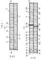
- FIG. 1(a) is a rear view taken along the ventilation direction, showing the overall
structure of a heat exchanger in which the tank for a heat exchanger according to the
present invention is used and FIG. 1(b) is a side elevation showing the overall structure of
the heat exchanger viewed from the side on which the heat exchange medium
intake/outlet portion is present;
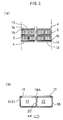
- FIG. 2(a) is an enlarged sectional view taken along line A - A in FIG. 1, FIG. 2(b) is
an enlarged sectional view taken along line B - B in FIG. 1 and FIG. 2(c) shows the heat
exchanging tubes and the fins;
- FIG. 3(a) shows the heat exchanging tubes and the fins and FIG. 3(b) is a sectional
view of the tank;
- FIGS. 4(a) through 4(g) each show a heat exchanger manufacturing step;
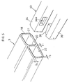
- FIG. 5 is a partial perspective showing the structure of the tank partition portion,
the wall thickness of the perimeter portion and the structure of the punch unit (the punch
and the die);
- FIG. 6 is a sectional view of the communication passage formed by inserting the
die arm and the punch arm at the chambers in the tank;
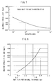
- FIG. 7 presents a diagram illustrating the relationship between the number of times
the punch unit can be repeatedly used and the allowable die arm stress limit; and
- FIG. 8 presents a diagram illustrating the relationship between the wall thickness of
the partition portion and the maximum stress occurring at the die arm.
-
BEST MODE FOR CARRYING OUT THE INVENTION
-
The following is an explanation of an embodiment of the present invention, given
in reference to the drawings.
-
A heat exchanger 1 shown in FIG. 1 may be used, for instance, as an evaporator
constituting part of a freezing cycle of an on-vehicle air-conditioning system. The heat
exchanger 1 manufactured through a furnace brazing method comprises a pair of tanks 2
and 3, a plurality of heat exchanging tubes 4 communicating between the tanks 2 and 3,
corrugated outer fins 5 inserted and bonded between the individual heat exchanging tubes
4, side plates 6 disposed at the two ends of the layered heat exchanging tube assembly
along the layering direction and a side tank 10 at which a connector 9 having heat
exchange medium intake/ outlet portions 7 and 8 is mounted. The connector 9 is
connected with an expansion valve (not shown). At the heat exchanger 1, a heat exchange
medium supplied through the expansion valve (not shown) flows in via the side tank 10,
the heat exchange medium then exchanges heat with the air passing between the outer fins
5 while traveling between the tank 2 and the tank 3 through the heat exchanging tubes 4
and finally the heat exchange medium exits via the side tank 10.
-
As shown in FIG. 3(a), each heat exchanging tube 4 has two open ends at which it
is inserted at the tanks 2 and 3 and is formed by housing inner fins 15 inside a flat tube 13
having formed therein a heat exchange medium flow passage 14. In this embodiment, the
heat exchanging tubes 4 are formed by bending a single sheet of flat tube material through
roll forming.
-
As described earlier, the tanks 2 and 3 are set so as to face opposite each other over
a predetermined distance and are both formed through extrusion molding. For this reason,
they are formed by using, for instance, an aluminum alloy in the A3000 group with no
brazing material layer formed at the surfaces thereof.
-
To explain the tank 2 in reference to FIG. 2(a), the tank 2 includes tube insertion
holes 17 at which the heat exchanging tubes 4 are inserted, and has openings each formed
at an end along the lengthwise direction. The openings are each closed off with a cap 19.
The tank 2 also includes a partition portion 20 extending along the direction in which the
heat exchanging tubes 4 are layered (along the longer side of the tank 2) and formed as an
integrated part of a perimeter portion 18. Thus, the inner space of the tank 2 is divided into
a chamber 21 and a chamber 22 set parallel along the ventilation direction, as shown in
FIG. 3(b).
-
The tank 3, too, includes tube insertion holes 17 at which the heat exchanging tubes
4 are inserted and has openings formed at the two ends along the lengthwise direction
which are closed off with caps 19, as shown in FIG. 2(b). In addition, a partition portion
20 extending along the direction in which the heat exchanging tubes 4 are layered (along
the longer side of the tank 3) is formed as an integrated part of the tank to divide the inner
space of the tank 3 into a chamber 21 and a chamber 22 set parallel along the ventilation
direction, as shown in FIG. 3(b), in the structure substantially similar to that of the tank 2.
However, unlike the chambers in the tank 2, the chamber 21 and the chamber 22 at the
tank 3 are each further divided into sub-chambers 21a and 21b or 22a and 22b with a
partitioning plate 28 inserted through a slit 29 to partition the chamber halfway through
along the ventilation direction. In order to achieve a four-pass flow of the heat exchange
medium, the sub-chamber 21b and the sub-chamber 22b are made to communicate with
each other through a communication passage 16.
-
The tank 3 includes a projecting portion 3a that projects further out along the tube
layering direction relative to the heat exchanging tube 4 at the terminating end of the
layered tube assembly. This projecting portion 3a is formed by distending the perimeter
portion 18, and the partition portion 20 is also allowed to extend to come into contact with
the inner side surface of the cap 19. Thus, the chambers 21 and 22 of the tank 3 mentioned
earlier are still partitioned from each other inside the projecting portion 3a. In the
projecting portion 3a, the chambers 21 and 22 constitute the upstream-most side and the
downstream-most side with regard to the heat exchange medium flow and, as shown in
FIG. 2(b), the chambers 21 and 22 are made to communicate respectively with an
inflow-side passage 25 and an outflow-side passage 26 at the side tank 10 via openings 23
and 24 formed at the projecting portion 3a.
-
Next, part of the process for manufacturing the heat exchanger 1, during which the
tank 3 is formed, is explained in reference to FIG. 4. First, as shown in FIG. 4(a), a tank
base piece M extracted from a plurality of tank base pieces M formed through extrusion
molding so as to achieve a significant elongation (e.g., 5 m) and held in stock is set on the
production line. Then, after punching the communication passage 16 at the partition
portion 20 over an area near the front end of the tank base piece M on one side thereof, as
shown in FIG. 4(b), tube insertion holes 17 are formed over a predetermined range at a
surface 18A of the tank base piece M as shown in FIG. 4(c). In addition, as shown in FIG.
4(d), the tank base piece M is cut so as to achieve a desired measurement along the
lengthwise direction by using a tool such as a circular saw, slits 29 and 29 are formed so
as to run over surfaces 18A, 18B and 18D and surfaces 18A, 18C (not shown, faces
opposite the surface 18B) and 18D, and the cut areas are washed to remove burrs and the
like. Thus, the tank 3 achieves a desired shape. The steps for forming the communication
passage 16, for forming the tube insertion holes 17, for forming the slits 29 and 29 and the
like are repeatedly executed until the tank base piece M is consumed.
-
Next, as shown in FIG. 4(e), a partitioning plate 28 is mounted in the chamber 21 or
the chamber 22 through the slit 29 at the finished tank 3. Lastly, a brazing sheet 30 is
pasted to the tube insertion hole forming surface 18A of the tank 3, as shown in FIG. 4(f),
and then the tank assembly process is completed by closing off the openings at the two
ends of the tank along the lengthwise direction with the caps 19, as shown in FIG. 4(g).
-
Since the tank 2 does not include a communication passage 16 and it does not need
slits 29 and 29 to be formed therein to allow partitioning plates 28 to be mounted inside
the chambers 21 and 22 through the slits, the tank 2 is formed by cutting the tank base
piece M with a tool instead of executing the step shown in FIG. 4(d) after the steps shown
in FIGS. 4(a) and 4(c), then pasting a brazing material sheet 30 at the tube insertion hole
forming surface 18A of the tank 2, as shown in FIG. 4(f) and closing off the openings at
the two ends of the tank 2 along the lengthwise direction with the caps 19, as shown in
FIG. 4(g).
-
After assembling the heat exchanger 1 by inserting the two ends of the longer side
of each heat exchanging tube 4 at a tube insertion hole 17 at the tank 2 and a tube insertion
hole 17 at the tank 3, the heat exchanger assembly is braised in the furnace, and thus, the
production of the heat exchanger 1 is completed. It is to be noted that since the heat
exchanger 1 is assembled and braised in a furnace by adopting methods in the known art,
the assembly and brazing processes are not illustrated in the drawings and their
explanation is omitted.
-
In this embodiment, the partition portion 20, which is formed as an integrated part
of the perimeter portion 18 while the perimeter portion 18 is formed during the process of
manufacturing the tank 3 through extrusion molding, has a wall thickness T1 of 1.0 mm,
whereas the perimeter portion 18 has a wall thickness T2 of 1.5 mm at the surface ranging
along the ventilation direction and a wall thickness T3 of 1.0 mm at the surface ranging
along the direction intersecting the ventilation direction, as shown in FIG. 5. Namely, the
wall thicknesses T2 and T3 assumed at the perimeter portion 18 are either equal to or
greater than the wall thickness T1 of the partition portion 20. It is to be noted that the wall
thickness T1 of the partition portion 20 does not need to be 1.0 mm as described above,
and may take any value within a range of equal to or greater than 0.4 mm and equal to or
less than 1.65 mm.
-
Then, the communication passage 16 is formed at the partition portion 20 as shown
in FIG. 4(b) by using a punch unit 33 having a die arm 34 with a die hole 34a formed
therein, a punch 35 assuming an external shape which allows it to be inserted through the
die hole 34a at the die arm 34 and a punch arm 36 used to move the punch 35 toward the
die arm 34, such as that shown in FIG. 5. Namely, after inserting the die arm 34 and the
punch arm 36 respectively through the openings of the chambers 21 and 22 at an end
along the lengthwise direction, the die ann 34 is fixed along the surface of the partition
portion 20, the front end of the punch 35 is moved toward the die arm 34 until it becomes
inserted at the die hole 34a in the die arm 34 by moving the punch arm 36 and then a
rectangular through hole, which is to constitute the communication passage 16, is
punched at the partition portion 20 through press machining, as shown in FIG. 6.
-
While the fulcrum and the power point of the die arm 34 and the punch 35 are not
set on a single axis extending along the press operating direction, the wall thickness T 1
equal to or smaller than 1.65 mm assumed at the partition portion 20, which is relatively
small compared to the wall thicknesses of partition portions in the related art, reduces the
extent of metal fatigue occurring at the punch unit 33.
-
In other words, the punch unit is required to have durability assuring approximately
100,000 repeated uses without incident in practical application. The allowable press stress
limit at which a punch unit constituted of SKH51, a material typically used to form press
molds and punches, can withstand 100,000 repeated uses is approximately 850 Nmm2, as
shown in FIG. 7, and the thickness of the partition portion that can be machined at such a
stress level is equal to or less than 1.65 mm, as shown in FIG. 8. For these reasons, the
upper limit to the plate thickness of the partition portion that assures 100,000 repeated
uses is set to 1.65 mm. It has also been learned that a sufficient level of strength to
withstand the force with which the front end of the partitioning plate 28 is abutted against
the partition portion 20 when mounting the partitioning plate 28 through the slit 29 at the
tank 3, as shown in FIG. 4(e), and the force that may be applied to the partition portion 20
in a specific operating environment is assured by keeping the lower limit to the wall
thickness of the partition portion 20 to 0.4 mm at which deformation of the partition
portion 20 does not occur.
INDUSTRIAL APPLICABILITY
-
As described above, in the tank for a heat exchanger according to the present
invention, having a partition portion formed as an integrated part of the perimeter portion
of the tank through extrusion molding, chambers are allowed to communicate with one
another through a communication passage formed at the partition portion as a hole instead
of a notch during a post-process and, as a result, the relative strength of the tank is
improved.
-
In addition, according to the present invention disclosed in claims 3 and 4, the wall
thickness of the partition portion is set within a range of equal to or greater than 0.4 mm
and equal to or less than 1.65 mm. By forming the partition portion with a relatively small
wall thickness compared to partition portions in the related art, a higher level of punch
unit fatigue strength is achieved so as to assure a specific number of repeated uses without
incident even though the communication passage is formed by using a punch and a die
with the fulcrum and the power point thereof not on a single axis along the operating
direction. At the same time, while the partition portion has a relatively small wall
thickness, a sufficient level of strength to prevent deformation of the partition portion is
still assured, and thus, the partition portion does not become deformed when a
partitioning plate is inserted through a slit formed over the perimeter portion of the tank or
in a specific operating environment.