JP4613402B2 - Vehicle steering device - Google Patents
Vehicle steering device Download PDFInfo
- Publication number
- JP4613402B2 JP4613402B2 JP2000254210A JP2000254210A JP4613402B2 JP 4613402 B2 JP4613402 B2 JP 4613402B2 JP 2000254210 A JP2000254210 A JP 2000254210A JP 2000254210 A JP2000254210 A JP 2000254210A JP 4613402 B2 JP4613402 B2 JP 4613402B2
- Authority
- JP
- Japan
- Prior art keywords
- steering shaft
- column
- pair
- clamp members
- outer column
- Prior art date
- Legal status (The legal status is an assumption and is not a legal conclusion. Google has not performed a legal analysis and makes no representation as to the accuracy of the status listed.)
- Expired - Lifetime
Links
Images


Landscapes
- Steering Controls (AREA)
Description
【0001】
【発明の属する技術分野】
本発明は車両用ステアリング装置に関する。特に本発明は、運転者の運転姿勢に応じて、ステアリングシャフトの傾斜角度および/もしくはステアリングシャフトの軸方向位置を調整できる車両用ステアリング装置に関する。
【0002】
【従来の技術】
車両用ステアリング装置には、運転者の運転姿勢に応じて、ステアリングホイールの傾斜角度を調整できると共に、ステアリングホイールの軸方向位置を調整できるチルト・テレスコピック式のステアリング装置がある。
【0003】
例えば、特開平11−278283号公報に開示したチルト・テレスコピック式のステアリング装置では、ロアー側のアウターコラムに、アッパー側のインナーコラムが摺動自在に挿入して嵌合してある。このアッパー側のインナーコラムには、テレスコ調整用溝を有するディスタンスブラケットが取り付けてあり、このディスタンスブラケットは、チルト調整用溝を有する車体側ブラケットの内側に摺接するように構成してある。テレスコ調整用溝及びチルト調整用溝には、締付ボルトが通挿してあり、この締付ボルトの一端には、操作レバーが取り付けてある。
【0004】
これにより、操作レバーを揺動すると、締付ボルトが軸方向に移動して、車体側ブラケットとディスタンスブラケットの締め付けを解除し、締付ボルトをチルト調整用溝に沿って上下方向に移動して、アッパー側のインナーコラムの傾斜角度を調整できると共に、インナーコラムはディスタンスブラケットのテレスコ調整用溝に沿って軸方向に移動して、軸方向位置を調整することができる。
【0005】
チルトおよびテレスコピック調整後には、操作レバーを逆方向に揺動すると、締付ボルトが軸方向に移動して、車体側ブラケットをディスタンスブラケットに押圧し、これにより、アッパー側のインナーコラムをチルトおよびテレスコピック調整後の状態で締め付けることができる。また、このように、一つの操作レバーの揺動により、チルト調整とテレスコピック調整との両方を行うことができる。
【0006】
【発明が解決しようとする課題】
上記公報に開示したチルト・テレスコピック式のステアリング装置では、ロアー側のアウターコラムに、アッパー側のインナーコラムを摺動自在に嵌合し、両コラムの剛性を高くしている。
【0007】
しかしながら、アッパー側のインナーコラムは、ロアー側のアウターコラムに対して必ずしも直接的にクランプしていないため、ステアリングホイールに曲げ荷重が作用した場合(即ち、ステアリングホイールが上下方向にこじられた場合)、アッパー側のインナーコラムは、若干揺動するように動くことがあり、両コラムの剛性は、必ずしも高いとはいえなかった。
【0008】
なお、アッパー側のインナーコラムに設けたディスタンスブラケットに、複数枚の補強板を設けて、剛性を高くすることも考えられるが、部品点数の増加から、製造コストの高騰を招くといった虞れがある。
【0009】
本発明は、上述したような事情に鑑みてなされたものであって、ステアリングコラムの剛性を著しく高くしたチルトおよび/もしくはテレスコピック位置が調整自在な車両用ステアリング装置を提供することを目的とする。
【0010】
【課題を解決するための手段】
上記の目的を達成するため、請求項1の発明に係る車両用ステアリング装置は、
ステアリングシャフトの一方の端部側を回転自在に支持するインナーコラムと、
前記ステアリングシャフトの他方の端部側を回転自在に支持すると共に、前記インナーコラムを摺動自在に嵌合したアウターコラムと、
このアウターコラムに一体に形成され、車体側ブラケットに摺接する面と前記インナーコラムを包持する包持面とをそれぞれ備えた一対のクランプ部材と、
これら一対のクランプ部材を互いに近接するように移動させて、前記インナーコラムをこれら一対のクランプ部材により締め付け包持するための締付手段と、
前記一対のクランプ部材よりも車両前方側で前記アウターコラムに設けられ、ステアリングシャフトをチルト回動可能にするために前記アウターコラムに設けられた支持部と、
該支持部に形成された筒状開口部に挿通されステアリングシャフトを車体側にチルト回動自在に支持するボルトと、を具備し、
しかして前記締付手段の締め付けを解除してステアリングシャフトを軸方向に移動して、ステアリングシャフトのテレスコピック位置及びチルト位置が調整自在である車両用ステアリング装置において、
前記アウターコラムは前記一対のクランプ部材と前記支持部と共に一体に形成された鋳物であることを特徴とする。
【0012】
さらに、上記の目的を達成するための請求項2に記載の発明に係る車両用ステアリング装置は、
ステアリングシャフトの一方の端部側を回転自在に支持するインナーコラムと、
前記ステアリングシャフトの他方の端部側を回転自在に支持すると共に、前記インナーコラムを摺動自在に嵌合し、車体側に回動自在に支持されたアウターコラムと、
このアウターコラムに一体に形成され、車体側ブラケットに摺接する面と前記インナーコラムを包持する包持面とをそれぞれ備えた一対のクランプ部材と、
これら一対のクランプ部材を互いに近接するように移動させて、前記インナーコラムをこれら一対のクランプ部材により締め付け包持するための締付手段と、
前記一対のクランプ部材よりも車両前方側で前記アウターコラムに設けられ、ステアリングシャフトをチルト回動可能にするために前記アウターコラムに設けられた支持部と、
該支持部に形成された筒状開口部に挿通されステアリングシャフトを車体側にチルト回動自在に支持するボルトと、を具備し、
しかして前記締付手段の締め付けを解除してステアリングシャフトのチルト位置が調整自在である車両用ステアリング装置において、前記アウターコラムは前記一対のクランプ部材と前記支持部と共に一体に形成された鋳物であることを特徴とする。
【0013】
さらに、上記の目的を達成するための請求項3に記載の発明に係る車両用ステアリング装置は、
ステアリングシャフトの一方の端部側を回転自在に支持するインナーコラムと、
前記ステアリングシャフトの他方の端部側を回転自在に支持すると共に、前記インナーコラムを摺動自在に嵌合したアウターコラムと、
このアウターコラムに径方向外方に向けて設けられ、車体側ブラケットに摺接する面と前記インナーコラムを包持する包持面とを内周面にそれぞれ備えた一対のクランプ部材と、
これら一対のクランプ部材を互いに近接するように移動させて、前記インナーコラムをこれら一対のクランプ部材により締め付け包持するための締付手段と、
前記一対のクランプ部材よりも車両前方側で前記アウターコラムに設けられ、ステアリングシャフトをチルト回動可能にするために前記アウターコラムに設けられた支持部と、
該支持部に形成された筒状開口部に挿通されステアリングシャフトを車体側にチルト回動自在に支持するボルトと、を具備し、
しかして前記締付手段の締め付けを解除してステアリングシャフトを軸方向に移動して、ステアリングシャフトのテレスコピック位置及びチルト位置が調整自在である車両用ステアリング装置において、
前記アウターコラムは前記一対のクランプ部材と前記支持部と共に一体に形成された鋳物であることを特徴とする。
【0014】
このように、本願各請求項に記載の発明に係る車両用ステアリング装置においては、インナーコラムをアウターコラムにより直接的にクランプするように構成していることから、ステアリングホイールに曲げ荷重が作用した場合(即ち、ステアリングホイールが上下方向にこじられた場合)であっても、インナーコラムは、若干揺動するように動くことがなく、両コラムの剛性を著しく高くすることができる。
【0015】
【発明の実施の形態】
以下、本発明の実施の形態に係るチルト・テレスコピック式の車両用ステアリング装置を図面を参照しつつ説明する。
(第1実施の形態)
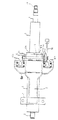
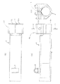
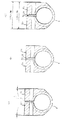
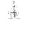
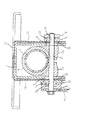
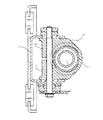
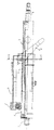
図1は、本発明の第1実施の形態に係るチルト・テレスコピック式の車両用ステアリング装置の平面図である。図2は、図1に示したステアリング装置の縦断面図である。図3は、図2のA−A線に沿った横断面図である。図4は、図2のB−B線に沿った横断面図である。図5(a)は、ロアー側のアウターコラムの平面図であり、図5(b)は、このアウターコラムの側面図であり、図5(c)は、図5(b)のC−C線に沿った横断面図である。
【0016】
図1および図2に示すように、ステアリングシャフトは、車両後方側端部でステアリングホイール(図示なし)を固設支持するアッパーシャフト1と、これにスプライン嵌合したロアーシャフト2とから伸縮自在に構成してあり、ステアリングコラムは、アッパーシャフト1を上端部で玉軸受31を介して回転自在に支持するアッパー側のインナーコラム3と、ロアーシャフト2を下端部で玉軸受33を介して回転自在に支持すると共にアッパー側のインナーコラム3に嵌合したロアー側のアウターコラム4とから摺動自在に構成してある。アッパーシャフト1には該アッパーシャフトがインナーコラム3に潜り込まないように潜り込み防止用のCーリング35が設けてあり、またロアシャフト2にも該ロアシャフト2がアウターコラム4に潜り込まないように潜り込み防止用Cーリング37が設けてある。
【0017】
このロアー側のアウターコラム4の周囲には、図3および図4にも示すように、チルト調整用溝5を有するブラケット6が設けてある。ブラケット6は車両後方側に車体に接続されるフランジ部6a有し全体として下向きに逆U字形状をしており、対向側板部6b、6cを一体に形成している。
【0018】
図4に示すように、車体側ブラケット6のロアー側には、別体のロアーブラケット7が車体側ブラケット6を包持するように設けてある。ロアーブラケット7は車体に連結される上板部7aとブラケット6の対向側板部6b、6cを接触挟持する下向きの対向側板部7b、7cを形成している。ブラケット6の対向側板部6b、6cの内側に両側端が摺接するように、筒状部8がアウターコラム4の前方端に一体的に形成してある。これらロアーブラケット7の対向側板部7b、7c、ブラケット6の対向側板部6b、6c、および筒状部8には、スペーサ筒9を介して、チルト中心ボルト10aが通挿してあり、ナット10bにより締め付けられている。これにより、ロアー側のアウターコラム4は、このチルト中心ボルト10aを中心として傾動できるようになっている。なお、図2に示すように、ロアーブラケット7には、二次衝突のコラプス時にチルト中心ボルト10が離脱するための離脱用オープンスリット11が形成してある。
【0019】
ロアー側のアウターコラム4はアッパーシャフト1とロアーシャフト2との嵌合部をほぼ覆う位置まで後方に延びており、さらにこの嵌合部よりも後方側にはある長さ範囲にわたりアウタージャケット部4aを一体に有している。アウタージャケット部4aには上方部中央に軸方向のすり割りlが形成してあり、アッパー側のインナーコラム3を包持してクランプするための一対のクランプ部材12a,12bを形成している。クランプ部材12a、12bはそれぞれインナーコラム3の外周面に適合する形状の内周面と車体側ブラケット6の内側に摺接する外側面とを有している。尚、クランプ部材12a、12bの内周面はインナーコラム3の外周面に円周方向180度以上に亘り摺接することが望ましい。また図14に示すように円周方向少なくとも3方向から摺接するようにしても良い。クランプ部材12a,12bには、締付ボルト13が通挿してある。この締付ボルト13のネジ部には、締付ナット14およびロックナット15が螺合してある。
【0020】
この締付ボルト13の頭部側には、操作レバー16が取り付けてあると共に、カムロック機構が設けてある。このカムロック機構は、操作レバー16と一体的に回転する第1カム部材17と、この第1カム部材17の回転に伴って、第1カム部材17の山部または谷部に係合しながら軸方向に移動してロックまたはロック解除する非回転の第2カム部材18とから構成してある。なお、第1カム部材17の突起17aが操作レバーに嵌合してあることにより、第1カム部材17は操作レバー16と一体的に回転できるように構成してあると共に、第2カム部材18の突起18aがチルト調整用溝5に嵌合してあることにより、第2カム部材18は常時非回転に構成してある。また、ブラケット6のフランジ部6aには、二次衝突のコラプス時の離脱用カプセル19a,19bが設けてある。すなわち、ブラケット6は離脱用カプセル19a、19bを介して車体に連結される。
【0021】
以上のように構成してあるため、車両衝突時には、アウターコラム4、インナーコラム3、ロアーシャフト2およびアッパシャフト1から成るステアリングシャフト組立体はブラケット6とともにロアーブラケット7に対して、車両前方に移動する。
【0022】
チルト・テレスコピックの解除時には、操作レバー16を所定方向に揺動すると、第1カム部材17が同時に回転して、第2カム部材18の山部から谷部に係合し、第2カム部材18が図3の左方に移動して、車体側ブラケット6のアウターコラム4への摺接固定を解除する。
【0023】
これにより、チルト調整の場合には、締付ボルト13をチルト調整用溝5に沿って移動し、チルト中心ボルト10を中心として、アウターコラム4およびインナーコラム3を傾動し、ステアリングホイール(図示略)の傾斜角度を所望に調整することができる。
【0024】
テレスコピック調整の場合には、ロアー側のアウターコラム4に対して、アッパー側のインナーコラム3を軸方向に摺動し、ステアリングホイール(図示略)の軸方向位置を所望に調整することができる。なお、アウターコラム4の外周下側の突出部に半径方向内向きのストッパボルト43が設けてある。ストッパボルト43に対向してインナーコラム3には所定長の長溝3bが形成してあり、この長溝3bにストッパボルト43の内端が係合しており、テレスコ位置調整用ストッパおよび回り止め部材となっている。
【0025】
チルト・テレスコピックの締付時には、操作レバー16を逆方向に揺動すると、第1カム部材17が同時に回転して、第2カム部材18の谷部から山部に係合し、第2カム部材18が図3の右方に移動して、締付ボルト13により、車体側ブラケット6がアウターコラム4を押圧する。
【0026】
これにより、これら一対のクランプ部材12a,12bは、互いに近接するように移動して、アッパー側のインナーコラム3を包持するようにクランプする。このように、アッパー側のインナーコラム3をロアー側のアウターコラム4により直接的にクランプするように構成していることから、ステアリングホイール(図示略)に曲げ荷重が作用した場合(即ち、ステアリングホイール(図示略)が上下方向にこじられた場合)であっても、アッパー側のインナーコラム3は、若干揺動するように動くことがなく、両コラム3,4の剛性を著しく高くすることができる。
【0027】
次に、図6に、第1実施の形態の変形例を示す。図6(a)は、第1実施の形態に係るロアー側のアウターコラムの断面図であり、図6(b)は、第1実施の形態の変形例に係るロアー側のアウターコラムの断面図であり、図6(c)は、本変形例に係るロアー側のアウターコラムの作用を示す断面図である。
【0028】
図6(a)に示すように、上述した第1実施の形態において、一対のクランプ部材12a,12bの間の「すり割りl」を形成した箇所では、その隙間が大きすぎ、アウターコラム4とインナーコラム3との間の隙間が大きい場合、クランプ時に、一対のクランプ部材12a,12bが傾斜するといった虞れがある。
【0029】
これに対処するため、図6(b)(c)に示すように、一対のクランプ部材12a,12bの間の「すり割り」を形成した箇所に、それぞれ、一対の突起12c,12dを設けている。これにより、クランプ時には、一対の突起12c,12dが互いに当接することから、一対のクランプ部材12a,12bを平行に維持することができ、充分な保持力を得ることができる。
図14に示す第1実施の形態の第2変形例においては、クランプ部材12a、12bの内周側ほぼ等角配置の3カ所においてインナーコラム3の外周に摺接している。尚、アウターコラム4は図18のようにすり割lを図5よりも前方へ長く伸ばしても良い。またアウターコラム4は鋳物、例えばアルミ鋳物、亜鉛鋳物、マグネシウム系鋳物、鉄系鋳物で作っても良い。
(第2実施の形態)
図7は、本発明の第2実施の形態に係るチルト・テレスコピック式の車両用ステアリング装置の平面図である。図8は、図7に示したステアリング装置の縦断面図である。図9は、図8のD−D線に沿った横断面図である。図10は、図8のE−E線に沿った横断面図である。
【0030】
本第2実施の形態は、上述した第1実施の形態に対して、二次衝突時の離脱方法が異なり、以下の構成を除いてその他の構成は、全て同じである。
【0031】
第2実施の形態において、ブラケット6は車両後方フランジ部6aと前方フランジ部6dとを一体に有しており、ブラケット6はこれらフランジ部で車体側に衝突時にも離脱不可能に固設保持されている。
【0032】
図8に示すように、アウターコラム4に一体のアウタージャケット4aを形成する一対のクランプ部材12a,12bには、締付ボルト13の後方側に、二次衝突のコラプス時に締付ボルト13が離脱するための離脱用オープンスリット20が形成してある。
【0033】
また、チルト中心ボルト10側では、第1実施の形態の筒状部に代えて、アウターコラム4には、フック8が一体的に形成してあり、このフック8の後方側に、二次衝突のコラプス時にチルト中心ボルト10が離脱するための離脱用オープンスリット21が形成してある。
【0034】
本第2実施の形態では、車両衝突時に車体側のブラケット6に対して、アウターコラム4、インナーコラム3、ロアーシャフト2およびアッパシャフト1から成るステアリングシャフト組立体は、車両前方に移動する。
(第3実施の形態)
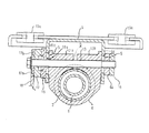
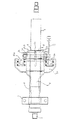
図11は、本発明の第3実施の形態に係るチルト・テレスコピック式の車両用ステアリング装置の縦断面図の要部である。図12は、図11のF−F線に沿った横断面図である。
【0035】
アッパー側のインナーコラム3を摺動自在に嵌合したロアー側のアウターコラム4は、車両後方側に一体に一対のクランプ部材12a,12bを構成するアウタージャケットが設けられているが、本実施形態においてはクランプ部材がインナーコラムをクランプする位置がロアー側のアウターコラム4の下側になっている。
【0036】
図11および図12に示すように、ブラケット6の車両後方側で、クランプ部材がインナーコラムを締め付ける位置には、テレスコピック方向の保持力を増強するため、テレスコ調整用溝25を有する補強用テレスコブラケット26が設けてある。テレスコブラケット26はインナーコラム3に固定されている。また、ブラケット6の外周囲に、チルト時の保持力を増強するため、チルト調整用溝23を有する補強用チルトブラケット24が設けてある。チルトブラケット24はブラケット6に固定されている。
【0037】
本第3実施の形態においても、チルト・テレスコピックの調整時には、操作レバー16を所定方向に揺動すると、第1カム部材17が同時に回転して、第2カム部材18の山部から谷部に係合し、第2カム部材18が図13の左方に移動して、車体側ブラケット6のアウターコラム4への締め付けを解除する。
【0038】
これにより、チルト調整の場合には、締付ボルト13をチルト調整用溝5(および補強用チルトブラケット24のチルト調整用溝23)に沿って移動し、アウターコラム4およびインナーコラム3を傾動し、ステアリングホイール(図示略)の傾斜角度を所望に調整することができる。
【0039】
テレスコピック調整の場合には、テレスコ調整用溝25は締め付けボルト13に沿って移動し、ロアー側のアウターコラム4に対して、アッパー側のインナーコラム3をアッパシャフト1とともに軸方向に摺動し、ステアリングホイール(図示略)の軸方向位置を所望に調整することができる。
【0040】
チルト・テレスコピックの締付時には、操作レバー16を逆方向に揺動すると、第1カム部材17が同時に回転して、第2カム部材18の谷部から山部に係合し、第2カム部材18が図13の右方に移動して、締付ボルト13により、車体側ブラケット6が、補強用チルトブラケット24および補強用テレスコブラケット26を介して、アウターコラム4を押圧する。
【0041】
これにより、これら一対のクランプ部材12a,12bは、互いに近接するように移動して、アッパー側のインナーコラム3を包持するようにクランプする。
このように、アッパー側のインナーコラム3をロアー側のアウターコラム4により直接的にクランプするように構成していることから、ステアリングホイール(図示略)に曲げ荷重が作用した場合であっても、アッパー側のインナーコラム3は、若干揺動するように動くことがなく、両コラム3,4の剛性を著しく高くすることができる。
(第4実施の形態)
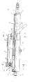
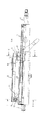
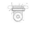
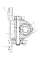
図13は、本発明の第4実施の形態に係るチルト・テレスコピック式の車両用ステアリング装置の縦断面図である。
【0042】
本第4実施の形態では、電動パワーステアリング装置27が設けてある。本実施形態において、電動パワーステアリング装置27のギヤボックス27aがアウターコラム4と一体に形成されており、車両前方端で車体側のロアー取り付けブラケット28にチルト中心ピン29により揺動自在に支持されている。また、ギヤボックス27aと一体のアウターコラム4後方には第1実施の形態同様一対のクランプ部材12a、12b(12bのみ図示)を形成するアウタージャケット4aが一体に形成されている。その他の構成は、上述した第1ないし第3実施の形態と同様である。
【0043】
ロアー側のアウターコラム4は、電動パワーステアリング装置27のギヤボックスと一体的に成型してあるが、別体で構成してもよい。
【0044】
本第4実施形態にあっても、操作レバー16を締め付け解除方向に回動し、クランプ部材のインナーコラム3に対する締め付けを解除してテレスコ調整およびチルト調整ができる。
【0045】
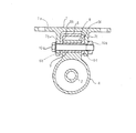
(第5実施の形態)
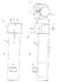
図15は、本発明の参考例である第5実施の形態に係るチルト・テレスコピック式の車両用ステアリング装置の平面図である。図16は、図15に示したステアリング装置の縦断面図である。図17は、図16のG−G線に沿った横断面図である。第5実施の形態については第1実施の形態と同じ部分については符号のみを示すかもしくは説明を省略し、第1実施の形態と異なる構成を主として以下に説明する。
【0046】
第5実施の形態において、アウターコラム4はクランプ部材12a、12bおよびアウタージャケット4aとは別体である。ロアー側のアウターコラム4はその後方端部におけるアッパー側のインナーコラムの前方端部と互いに嵌合し重なり合う部分において軸方向に延びる2つのスリ割り部L1,L2を径方向に対向して形成してある。
【0047】
一対のクランプ部材12a、12bの下方にはアウターコラム4の後方端部の外周に摺接しかつこれらクランプ部材12a,12bを一体にするアウタジャケット部4aを形成している。これらクランプ部材12a,12bとアウタジャケット部4aの形状および構成はアウターコラム4と別体であることを除いて第1実施の形態と同様である。
【0048】
第5実施の形態においては、このように形成された一対のクランプ部材12a,12bが一体のアウタージャケット部4aは、インナーコラム3とアウターコラム4とが重なり合う部分において外周側のアウターコラム4の外周に配置されアウターコラム4を直接インナーコラム3へとチルト調整位置もしくはテレスコ調整位置に締め付け固定する。
第5実施の形態の上記以外の構成、および作用については第1実施の形態と同じである。また、アウタージャケット4aは鋳物、例えばアルミ鋳物、亜鉛鋳物、マグネシウム系鋳物、鉄系鋳物で作っても良い。
【0049】
なお、本発明は、上述した実施の形態に限定されず、種々変形可能である。
【0050】
【発明の効果】
以上説明したように、本発明によれば、アウターコラムに一体または別体の、一対のクランプ部材がインナーコラムまたはアウターコラムを包持するように設けてあり、しかも、締付手段により、これら一対のクランプ部材を互いに近接するように移動させて、インナーコラムまたはアウターコラムをこれら一対のクランプ部材により包持してクランプするように構成している。したがって、このようにインナーコラムをアウターコラムにより直接的にクランプするように構成していることから、ステアリングホイールに曲げ荷重が作用した場合(即ち、ステアリングホイールが上下方向にこじられた場合)であっても、インナーコラムは、若干揺動するように動くことがなく、両コラムの剛性を著しく高くすることができる。
【図面の簡単な説明】
【図1】 本発明の第1実施の形態に係るチルト・テレスコピック式の車両用ステアリング装置の平面図である。
【図2】 図1に示したステアリング装置の縦断面図である。
【図3】 図2のA−A線に沿った横断面図である。
【図4】 図2のB−B線に沿った横断面図である。
【図5】 第1実施の形態のアウターコラムについて、(a)は、ロアー側のアウターコラムの平面図であり、(b)は、このアウターコラムの側面図であり、(c)は、(b)のC−C線に沿った横断面図である。
【図6】 (a)は、第1実施の形態に係るロアー側のアウターコラムの断面図であり、(b)は、第1実施の形態の変形例に係るロアー側のアウターコラムの断面図であり、(c)は、本変形例に係るロアー側のアウターコラムの作用を示す断面図である。
【図7】 本発明の第2実施の形態に係るチルト・テレスコピック式の車両用ステアリング装置の平面図である。
【図8】 図7に示したステアリング装置の縦断面図である。
【図9】 図8のD−D線に沿った横断面図である。
【図10】 図8のE−E線に沿った横断面図である。
【図11】 本発明の第3実施の形態に係るチルト・テレスコピック式の車両用ステアリング装置の縦断面図の要部である。
【図12】 図11のF−F線に沿った横断面図である。
【図13】 本発明の第4実施の形態に係るチルト・テレスコピック式の車両用ステアリング装置の縦断面図である。
【図14】 本発明の第1実施の形態の第2変形例に係る図3と同様な断面図である。
【図15】 本発明の参考例である第5実施の形態に係るチルト・テレスコピック式の車両用ステアリング装置の平面図である。
【図16】 図15に示したステアリング装置の縦断面図である。
【図17】 図16のG−G線に沿った横断面図である。
【図18】 本発明の第1実施の形態の第3変形例におけるアウターコラムについて、(a)は、ロアー側のアウターコラムの平面図であり、(b)は、このアウターコラムの側面図であり、(c)は、(b)のC−C線に沿った横断面図である。
【符号の説明】
1 アッパーシャフト
2 ロアーシャフト
3 アッパー側のインナーコラム
4 ロアー側のアウターコラム
5 チルト調整用溝
6 ブラケット
7 ロアーブラケット
8 筒状部
9 スペーサ
10 チルト中心ピン
11 離脱用オープンスリット
12 クランプ部材
13 締付ボルト(締付手段)
14 締付ナット
15 ロックナット
16 操作レバー
17 第1カム部材
18 第2カム部材
19 離脱用カプセル
20,21 離脱用オープンスリット
23 チルト調整用溝
24 補強用チルトブラケット
25 テレスコ調整用溝
26 補強用テレスコブラケット
27 電動パワーステアリング装置
28 ロアーブラケット
29 チルト中心ピン
31,33 玉軸受
35,37 Cーリング
43 ストッパボルト[0001]
BACKGROUND OF THE INVENTION
The present invention relates to a vehicle steering apparatus. In particular, the present invention relates to a vehicle steering apparatus that can adjust the inclination angle of the steering shaft and / or the axial position of the steering shaft in accordance with the driving posture of the driver.
[0002]
[Prior art]
As a vehicle steering apparatus, there is a tilt / telescopic type steering apparatus that can adjust the tilt angle of the steering wheel and adjust the axial position of the steering wheel according to the driving posture of the driver.
[0003]
For example, in a tilt / telescopic steering device disclosed in Japanese Patent Application Laid-Open No. 11-278283, an upper inner column is slidably inserted and fitted into a lower outer column. A distance bracket having a telescopic adjustment groove is attached to the inner column on the upper side, and the distance bracket is configured to be in sliding contact with the inner side of the vehicle body side bracket having the tilt adjustment groove. A fastening bolt is inserted through the telescopic adjustment groove and the tilt adjustment groove, and an operation lever is attached to one end of the fastening bolt.
[0004]
As a result, when the operating lever is swung, the tightening bolt moves in the axial direction to release the tightening of the vehicle body side bracket and the distance bracket, and the tightening bolt moves in the vertical direction along the tilt adjustment groove. The inclination angle of the inner column on the upper side can be adjusted, and the inner column can be moved in the axial direction along the telescopic adjustment groove of the distance bracket to adjust the axial position.
[0005]
After tilt and telescopic adjustment, if the operating lever is swung in the opposite direction, the tightening bolt moves in the axial direction and presses the body side bracket against the distance bracket, thereby tilting and telescopic the upper inner column. It can be tightened after adjustment. In this way, both tilt adjustment and telescopic adjustment can be performed by swinging one operation lever.
[0006]
[Problems to be solved by the invention]
In the tilt / telescopic steering device disclosed in the above publication, the inner column on the upper side is slidably fitted to the outer column on the lower side to increase the rigidity of both columns.
[0007]
However, since the upper inner column is not necessarily clamped directly against the lower outer column, when a bending load is applied to the steering wheel (ie, when the steering wheel is squeezed vertically). The inner column on the upper side sometimes moves so as to swing slightly, and the rigidity of both columns was not necessarily high.
[0008]
Although it is conceivable to increase the rigidity by providing a plurality of reinforcing plates on the distance bracket provided on the inner column on the upper side, there is a risk that the increase in the number of parts may cause an increase in manufacturing cost. .
[0009]
The present invention has been made in view of the above-described circumstances, and an object of the present invention is to provide a vehicle steering apparatus in which the tilt and / or telescopic position of the steering column can be adjusted to be extremely high.
[0010]
[Means for Solving the Problems]
In order to achieve the above object, a vehicle steering apparatus according to the invention of
An inner column that rotatably supports one end side of the steering shaft;
An outer column that rotatably supports the other end side of the steering shaft and slidably fits the inner column;
A pair of clamp members formed integrally with the outer column, each having a surface slidably contacting the vehicle body side bracket and a holding surface for holding the inner column;
A clamping means for moving the pair of clamp members so as to be close to each other and clamping and holding the inner column by the pair of clamp members;
A support portion provided on the outer column on the front side of the vehicle with respect to the pair of clamp members, and provided on the outer column to allow the steering shaft to be tilted and rotated;
A bolt that is inserted into a cylindrical opening formed in the support portion and supports the steering shaft so that the steering shaft can be tilted and rotated on the vehicle body side ;
Thus, in the vehicle steering device in which the fastening of the fastening means is released and the steering shaft is moved in the axial direction so that the telescopic position and the tilt position of the steering shaft are adjustable .
The outer column is a casting formed integrally with the pair of clamp members and the support portion .
[0012]
Furthermore, a vehicle steering apparatus according to the invention of
An inner column that rotatably supports one end side of the steering shaft;
An outer column that rotatably supports the other end side of the steering shaft and that is slidably fitted to the inner column and is rotatably supported on the vehicle body side;
A pair of clamp members formed integrally with the outer column, each having a surface slidably contacting the vehicle body side bracket and a holding surface for holding the inner column;
A clamping means for moving the pair of clamp members so as to be close to each other and clamping and holding the inner column by the pair of clamp members;
A support portion provided on the outer column on the front side of the vehicle with respect to the pair of clamp members, and provided on the outer column to allow the steering shaft to be tilted and rotated;
A bolt that is inserted into a cylindrical opening formed in the support portion and supports the steering shaft so that the steering shaft can be tilted and rotated on the vehicle body side ;
Thus, in the vehicle steering apparatus in which the tilting position of the steering shaft can be adjusted by releasing the tightening means , the outer column is a casting integrally formed with the pair of clamp members and the support portion. It is characterized by that.
[0013]
Furthermore, a vehicle steering apparatus according to the invention of
An inner column that rotatably supports one end side of the steering shaft;
An outer column that rotatably supports the other end side of the steering shaft and slidably fits the inner column;
A pair of clamp members provided on the outer column in a radially outward direction, each having a surface that slides on the vehicle body side bracket and a holding surface that holds the inner column ;
A clamping means for moving the pair of clamp members so as to be close to each other and clamping and holding the inner column by the pair of clamp members;
A support portion provided on the outer column on the front side of the vehicle with respect to the pair of clamp members, and provided on the outer column to allow the steering shaft to be tilted and rotated;
A bolt that is inserted into a cylindrical opening formed in the support portion and supports the steering shaft so that the steering shaft can be tilted and rotated on the vehicle body side;
Thus, in the vehicle steering device in which the fastening of the fastening means is released and the steering shaft is moved in the axial direction so that the telescopic position and the tilt position of the steering shaft are adjustable .
The outer column is a casting formed integrally with the pair of clamp members and the support portion .
[0014]
Thus, in the vehicle steering device according to the invention described in each claim of the present application, since the inner column is configured to be directly clamped by the outer column, a bending load acts on the steering wheel. Even when the steering wheel is twisted in the vertical direction, the inner column does not move so as to swing slightly, and the rigidity of both columns can be remarkably increased.
[0015]
DETAILED DESCRIPTION OF THE INVENTION
Hereinafter, a tilt and telescopic vehicle steering apparatus according to an embodiment of the present invention will be described with reference to the drawings.
(First embodiment)
FIG. 1 is a plan view of a tilt / telescopic vehicle steering apparatus according to a first embodiment of the present invention. FIG. 2 is a longitudinal sectional view of the steering apparatus shown in FIG. 3 is a cross-sectional view taken along line AA in FIG. FIG. 4 is a cross-sectional view taken along line BB in FIG. 5A is a plan view of the outer column on the lower side, FIG. 5B is a side view of the outer column, and FIG. 5C is a cross-sectional view taken along the line CC in FIG. 5B. It is a cross-sectional view along the line.
[0016]
As shown in FIGS. 1 and 2, the steering shaft is extendable and retractable from an
[0017]
As shown in FIGS. 3 and 4, a
[0018]
As shown in FIG. 4, a separate lower bracket 7 is provided on the lower side of the vehicle
[0019]
The
[0020]
An
[0021]
Due to the above configuration, the steering shaft assembly including the
[0022]
When the tilt / telescopic is released, if the
[0023]
Thus, in the case of tilt adjustment, the tightening
[0024]
In the case of telescopic adjustment, the position of the steering wheel (not shown) in the axial direction can be adjusted as desired by sliding the upper
[0025]
At the time of tilt / telescopic tightening, if the operating
[0026]
Accordingly, the pair of
[0027]
Next, FIG. 6 shows a modification of the first embodiment. 6A is a cross-sectional view of the lower-side outer column according to the first embodiment, and FIG. 6B is a cross-sectional view of the lower-side outer column according to a modification of the first embodiment. FIG. 6C is a cross-sectional view showing the operation of the lower outer column according to this modification.
[0028]
As shown in FIG. 6A, in the above-described first embodiment, the gap between the pair of
[0029]
In order to cope with this, as shown in FIGS. 6B and 6C, a pair of protrusions 12c and 12d are provided at locations where “slots” are formed between the pair of
In the second modification of the first embodiment shown in FIG. 14, the
(Second Embodiment)
FIG. 7 is a plan view of a tilt / telescopic vehicle steering apparatus according to a second embodiment of the present invention. FIG. 8 is a longitudinal sectional view of the steering apparatus shown in FIG. FIG. 9 is a cross-sectional view taken along the line DD of FIG. FIG. 10 is a cross-sectional view taken along the line EE of FIG.
[0030]
The second embodiment differs from the first embodiment described above in the separation method at the time of the secondary collision, and the other configurations are the same except for the following configurations.
[0031]
In the second embodiment, the
[0032]
As shown in FIG. 8, the clamping
[0033]
Further, on the
[0034]
In the second embodiment, the steering shaft assembly including the
(Third embodiment)
FIG. 11 is an essential part of a longitudinal sectional view of a tilt / telescopic vehicle steering apparatus according to a third embodiment of the present invention. 12 is a cross-sectional view taken along line FF in FIG.
[0035]
The lower
[0036]
As shown in FIGS. 11 and 12, a reinforcing telescopic bracket having a telescopic adjustment groove 25 at the position where the clamp member tightens the inner column on the vehicle rear side of the
[0037]
Also in the third embodiment, when the tilt / telescopic adjustment is performed, if the
[0038]
Thereby, in the case of tilt adjustment, the tightening
[0039]
In the case of telescopic adjustment, the telescopic adjustment groove 25 moves along the tightening
[0040]
At the time of tilt / telescopic tightening, if the operating
[0041]
Accordingly, the pair of
Since the upper
(Fourth embodiment)
FIG. 13 is a longitudinal sectional view of a tilt / telescopic vehicle steering apparatus according to a fourth embodiment of the present invention.
[0042]
In the fourth embodiment, an electric
[0043]
The
[0044]
Even in the fourth embodiment, telescopic adjustment and tilt adjustment can be performed by rotating the
[0045]
(Fifth embodiment)
FIG. 15 is a plan view of a tilt / telescopic vehicle steering apparatus according to a fifth embodiment which is a reference example of the present invention. 16 is a longitudinal sectional view of the steering apparatus shown in FIG. FIG. 17 is a cross-sectional view taken along line GG in FIG. In the fifth embodiment, the same parts as those in the first embodiment are indicated only by the reference numerals or the description thereof is omitted, and the configuration different from the first embodiment will be mainly described below.
[0046]
In the fifth embodiment, the
[0047]
Below the pair of
[0048]
In the fifth embodiment, the
The configuration and operation of the fifth embodiment other than those described above are the same as those of the first embodiment. The
[0049]
In addition, this invention is not limited to embodiment mentioned above, A various deformation | transformation is possible.
[0050]
【The invention's effect】
As described above, according to the present invention, a pair of clamp members, which are integral with or separate from the outer column, are provided so as to hold the inner column or the outer column. The clamp members are moved so as to be close to each other, and the inner column or the outer column is held and clamped by the pair of clamp members. Therefore, since the inner column is configured to be directly clamped by the outer column, the bending load is applied to the steering wheel (that is, the steering wheel is twisted in the vertical direction). However, the inner column does not move so as to slightly swing, and the rigidity of both columns can be remarkably increased.
[Brief description of the drawings]
FIG. 1 is a plan view of a tilt / telescopic vehicle steering apparatus according to a first embodiment of the present invention.
FIG. 2 is a longitudinal sectional view of the steering apparatus shown in FIG.
3 is a cross-sectional view taken along line AA in FIG.
4 is a cross-sectional view taken along the line BB in FIG. 2. FIG.
5A is a plan view of the lower outer column, FIG. 5B is a side view of the outer column, and FIG. 5C is a side view of the outer column of the first embodiment. It is a cross-sectional view along CC line of b).
6A is a cross-sectional view of a lower-side outer column according to the first embodiment, and FIG. 6B is a cross-sectional view of a lower-side outer column according to a modification of the first embodiment. (C) is sectional drawing which shows the effect | action of the lower side outer column which concerns on this modification.
FIG. 7 is a plan view of a tilt / telescopic vehicle steering apparatus according to a second embodiment of the present invention.
FIG. 8 is a longitudinal sectional view of the steering device shown in FIG.
9 is a cross-sectional view taken along the line DD in FIG.
10 is a transverse sectional view taken along the line EE of FIG.
FIG. 11 is a main part of a longitudinal sectional view of a tilt / telescopic vehicle steering apparatus according to a third embodiment of the present invention;
12 is a cross-sectional view taken along line FF in FIG.
FIG. 13 is a longitudinal sectional view of a tilt / telescopic vehicle steering apparatus according to a fourth embodiment of the present invention.
14 is a cross-sectional view similar to FIG. 3 according to a second modification of the first embodiment of the present invention. FIG.
FIG. 15 is a plan view of a tilt and telescopic vehicle steering apparatus according to a fifth embodiment which is a reference example of the present invention.
16 is a longitudinal sectional view of the steering device shown in FIG.
17 is a cross-sectional view taken along the line GG in FIG.
18A is a plan view of an outer column on the lower side, and FIG. 18B is a side view of the outer column according to a third modification of the first embodiment of the present invention. (C) is a cross-sectional view along the line CC of (b).
[Explanation of symbols]
DESCRIPTION OF
14 Tightening
Claims (6)
前記ステアリングシャフトの他方の端部側を回転自在に支持すると共に、前記インナーコラムを摺動自在に嵌合したアウターコラムと、
このアウターコラムに一体に形成され、車体側ブラケットに摺接する面と前記インナーコラムを包持する包持面とをそれぞれ備えた一対のクランプ部材と、
これら一対のクランプ部材を互いに近接するように移動させて、前記インナーコラムをこれら一対のクランプ部材により締め付け包持するための締付手段と、
前記一対のクランプ部材よりも車両前方側で前記アウターコラムに設けられ、ステアリングシャフトをチルト回動可能にするために前記アウターコラムに設けられた支持部と、
該支持部に形成された筒状開口部に挿通されステアリングシャフトを車体側にチルト回動自在に支持するボルトと、を具備し、
しかして前記締付手段の締め付けを解除してステアリングシャフトを軸方向に移動して、ステアリングシャフトのテレスコピック位置及びチルト位置が調整自在である車両用ステアリング装置において、
前記アウターコラムは前記一対のクランプ部材と前記支持部と共に一体に形成された鋳物であることを特徴とする車両用ステアリング装置。An inner column that rotatably supports one end side of the steering shaft;
An outer column that rotatably supports the other end side of the steering shaft and slidably fits the inner column;
A pair of clamp members formed integrally with the outer column, each having a surface slidably contacting the vehicle body side bracket and a holding surface for holding the inner column;
A clamping means for moving the pair of clamp members so as to be close to each other and clamping and holding the inner column by the pair of clamp members;
A support portion provided on the outer column on the front side of the vehicle with respect to the pair of clamp members, and provided on the outer column to allow the steering shaft to be tilted and rotated;
A bolt that is inserted into a cylindrical opening formed in the support portion and supports the steering shaft so that the steering shaft can be tilted and rotated on the vehicle body side ;
Thus, in the vehicle steering device in which the fastening of the fastening means is released and the steering shaft is moved in the axial direction so that the telescopic position and the tilt position of the steering shaft are adjustable .
The vehicle steering apparatus according to claim 1, wherein the outer column is a casting formed integrally with the pair of clamp members and the support portion .
前記ステアリングシャフトの他方の端部側を回転自在に支持すると共に、前記インナーコラムを摺動自在に嵌合し、車体側に回動自在に支持されたアウターコラムと、
このアウターコラムに一体に形成され、車体側ブラケットに摺接する面と前記インナーコラムを包持する包持面とをそれぞれ備えた一対のクランプ部材と、
これら一対のクランプ部材を互いに近接するように移動させて、前記インナーコラムをこれら一対のクランプ部材により締め付け包持するための締付手段と、
前記一対のクランプ部材よりも車両前方側で前記アウターコラムに設けられ、ステアリングシャフトをチルト回動可能にするために前記アウターコラムに設けられた支持部と、
該支持部に形成された筒状開口部に挿通されステアリングシャフトを車体側にチルト回動自在に支持するボルトと、を具備し、
しかして前記締付手段の締め付けを解除してステアリングシャフトのチルト位置が調整自在である車両用ステアリング装置において、前記アウターコラムは前記一対のクランプ部材と前記支持部と共に一体に形成された鋳物であることを特徴とする車両用ステアリング装置。An inner column that rotatably supports one end side of the steering shaft;
An outer column that rotatably supports the other end side of the steering shaft and that is slidably fitted to the inner column and is rotatably supported on the vehicle body side;
A pair of clamp members formed integrally with the outer column, each having a surface slidably contacting the vehicle body side bracket and a holding surface for holding the inner column;
A clamping means for moving the pair of clamp members so as to be close to each other and clamping and holding the inner column by the pair of clamp members;
A support portion provided on the outer column on the front side of the vehicle with respect to the pair of clamp members, and provided on the outer column to allow the steering shaft to be tilted and rotated;
A bolt that is inserted into a cylindrical opening formed in the support portion and supports the steering shaft so that the steering shaft can be tilted and rotated on the vehicle body side ;
Thus, in the vehicle steering apparatus in which the tilting position of the steering shaft can be adjusted by releasing the tightening means , the outer column is a casting formed integrally with the pair of clamp members and the support portion. A vehicle steering apparatus characterized by the above.
前記ステアリングシャフトの他方の端部側を回転自在に支持すると共に、前記インナーコラムを摺動自在に嵌合したアウターコラムと、
このアウターコラムに径方向外方に向けて設けられ、車体側ブラケットに摺接する面と前記インナーコラムを包持する包持面とを内周面にそれぞれ備えた一対のクランプ部材と、
これら一対のクランプ部材を互いに近接するように移動させて、前記インナーコラムをこれら一対のクランプ部材により締め付け包持するための締付手段と、
前記一対のクランプ部材よりも車両前方側で前記アウターコラムに設けられ、ステアリングシャフトをチルト回動可能にするために前記アウターコラムに設けられた支持部と、
該支持部に形成された筒状開口部に挿通されステアリングシャフトを車体側にチルト回動自在に支持するボルトと、を具備し、
しかして前記締付手段の締め付けを解除してステアリングシャフトを軸方向に移動して、ステアリングシャフトのテレスコピック位置及びチルト位置が調整自在である車両用ステアリング装置において、
前記アウターコラムは前記一対のクランプ部材と前記支持部と共に一体に形成された鋳物であることを特徴とする車両用ステアリング装置。An inner column that rotatably supports one end side of the steering shaft;
An outer column that rotatably supports the other end side of the steering shaft and slidably fits the inner column;
A pair of clamp members provided on the outer column in a radially outward direction, each having a surface that slides on the vehicle body side bracket and a holding surface that holds the inner column;
A clamping means for moving the pair of clamp members so as to be close to each other and clamping and holding the inner column by the pair of clamp members;
A support portion provided on the outer column on the front side of the vehicle with respect to the pair of clamp members, and provided on the outer column to allow the steering shaft to be tilted and rotated;
A bolt that is inserted into a cylindrical opening formed in the support portion and supports the steering shaft so that the steering shaft can be tilted and rotated on the vehicle body side;
Thus, in the vehicle steering device in which the fastening of the fastening means is released and the steering shaft is moved in the axial direction so that the telescopic position and the tilt position of the steering shaft are adjustable .
The vehicle steering apparatus according to claim 1, wherein the outer column is a casting formed integrally with the pair of clamp members and the support portion .
Priority Applications (4)
| Application Number | Priority Date | Filing Date | Title |
|---|---|---|---|
| JP2000254210A JP4613402B2 (en) | 2000-02-15 | 2000-08-24 | Vehicle steering device |
| EP01301278A EP1125820B2 (en) | 2000-02-15 | 2001-02-13 | Steering device for car |
| DE60133331T DE60133331T3 (en) | 2000-02-15 | 2001-02-13 | Steering for an automobile |
| US09/782,523 US6467807B2 (en) | 2000-02-15 | 2001-02-14 | Steering device for car |
Applications Claiming Priority (5)
| Application Number | Priority Date | Filing Date | Title |
|---|---|---|---|
| JP2000036936 | 2000-02-15 | ||
| JP2000-36936 | 2000-04-04 | ||
| JP2000-102693 | 2000-04-04 | ||
| JP2000102693 | 2000-04-04 | ||
| JP2000254210A JP4613402B2 (en) | 2000-02-15 | 2000-08-24 | Vehicle steering device |
Related Child Applications (6)
| Application Number | Title | Priority Date | Filing Date |
|---|---|---|---|
| JP2010129090A Division JP5195825B2 (en) | 2000-02-15 | 2010-06-04 | Vehicle steering device |
| JP2010129089A Division JP5195824B2 (en) | 2000-02-15 | 2010-06-04 | Vehicle steering device |
| JP2010129091A Division JP5195826B2 (en) | 2000-02-15 | 2010-06-04 | Vehicle steering device |
| JP2010129092A Division JP5195827B2 (en) | 2000-02-15 | 2010-06-04 | Vehicle steering device |
| JP2010129087A Division JP5195822B2 (en) | 2000-02-15 | 2010-06-04 | Vehicle steering device |
| JP2010129088A Division JP5195823B2 (en) | 2000-02-15 | 2010-06-04 | Vehicle steering device |
Publications (3)
| Publication Number | Publication Date |
|---|---|
| JP2001347953A JP2001347953A (en) | 2001-12-18 |
| JP2001347953A5 JP2001347953A5 (en) | 2007-09-13 |
| JP4613402B2 true JP4613402B2 (en) | 2011-01-19 |
Family
ID=27342363
Family Applications (1)
| Application Number | Title | Priority Date | Filing Date |
|---|---|---|---|
| JP2000254210A Expired - Lifetime JP4613402B2 (en) | 2000-02-15 | 2000-08-24 | Vehicle steering device |
Country Status (1)
| Country | Link |
|---|---|
| JP (1) | JP4613402B2 (en) |
Cited By (1)
| Publication number | Priority date | Publication date | Assignee | Title |
|---|---|---|---|---|
| US9481390B2 (en) | 2013-10-04 | 2016-11-01 | Nsk Americas, Inc. | Collapsible steering column assembly |
Families Citing this family (31)
| Publication number | Priority date | Publication date | Assignee | Title |
|---|---|---|---|---|
| JP4147579B2 (en) | 2002-01-17 | 2008-09-10 | 日本精工株式会社 | Steering device |
| EP1504980A4 (en) * | 2002-05-10 | 2006-04-26 | Nsk Ltd | Steering device |
| DE602004021364D1 (en) | 2003-03-26 | 2009-07-16 | Nsk Ltd | STEERING DEVICE FOR A MOTOR VEHICLE |
| JP4308040B2 (en) * | 2003-06-05 | 2009-08-05 | 日本精工株式会社 | Steering device |
| JP4390134B2 (en) | 2003-11-05 | 2009-12-24 | 日本精工株式会社 | Steering device |
| KR100585885B1 (en) * | 2004-02-10 | 2006-06-08 | 남양공업주식회사 | Steering Gear for Simultaneous Tilt and Telescopic Operation |
| US8505407B2 (en) * | 2004-07-27 | 2013-08-13 | Nsk Ltd. | Steering column device |
| JP4621458B2 (en) * | 2004-09-02 | 2011-01-26 | 日産ライトトラック株式会社 | Steering column support structure |
| JP2006306263A (en) * | 2005-04-28 | 2006-11-09 | Nsk Ltd | Steering device |
| US7699344B2 (en) | 2006-02-21 | 2010-04-20 | Nsk Ltd. | Steering device |
| JP4525608B2 (en) * | 2006-02-21 | 2010-08-18 | 日本精工株式会社 | Steering device |
| JP5050550B2 (en) * | 2007-02-13 | 2012-10-17 | 日本精工株式会社 | Steering device |
| JP5034548B2 (en) * | 2007-02-22 | 2012-09-26 | 日本精工株式会社 | Steering column device |
| DE112008003076B4 (en) | 2007-11-13 | 2019-06-19 | Nsk Ltd. | steering device |
| JP5358932B2 (en) * | 2007-11-13 | 2013-12-04 | 日本精工株式会社 | Steering device |
| JP5228454B2 (en) * | 2007-11-27 | 2013-07-03 | 日本精工株式会社 | Vehicle steering device |
| KR101494609B1 (en) * | 2008-09-16 | 2015-02-23 | 현대모비스 주식회사 | Steering column |
| JP5508613B2 (en) * | 2008-12-19 | 2014-06-04 | 株式会社山田製作所 | Telescopic steering device |
| JP5465426B2 (en) * | 2008-12-19 | 2014-04-09 | 株式会社山田製作所 | Tilt telescopic steering device |
| KR101267712B1 (en) | 2009-01-16 | 2013-05-23 | 주식회사 만도 | Steering Column for Vehicle |
| JP5279741B2 (en) * | 2009-03-30 | 2013-09-04 | 株式会社山田製作所 | Steering device |
| JP5218255B2 (en) * | 2009-04-28 | 2013-06-26 | 日本精工株式会社 | Steering device |
| KR101034631B1 (en) | 2009-06-01 | 2011-05-16 | 동서콘트롤(주) | Telescopic device of vehicle steering column |
| JP5788829B2 (en) * | 2012-04-06 | 2015-10-07 | 株式会社山田製作所 | Steering device |
| JP5956845B2 (en) * | 2012-06-27 | 2016-07-27 | 富士機工株式会社 | Steering column device |
| JP6527001B2 (en) | 2015-03-31 | 2019-06-05 | 富士機工株式会社 | Steering column device |
| JP2016190526A (en) | 2015-03-31 | 2016-11-10 | 富士機工株式会社 | Steering column device |
| JP6668619B2 (en) * | 2015-06-12 | 2020-03-18 | 日本精工株式会社 | Telescopic steering column device |
| JP6731229B2 (en) | 2015-10-16 | 2020-07-29 | 株式会社山田製作所 | Steering device and manufacturing method thereof |
| JP6777229B2 (en) | 2017-06-14 | 2020-10-28 | 日本精工株式会社 | Steering column device |
| JP7251138B2 (en) * | 2018-12-26 | 2023-04-04 | 株式会社ジェイテクト | steering device |
Family Cites Families (3)
| Publication number | Priority date | Publication date | Assignee | Title |
|---|---|---|---|---|
| JPS6034954U (en) * | 1983-08-19 | 1985-03-09 | 日本精工株式会社 | steering column device |
| FR2588047B1 (en) * | 1985-09-30 | 1988-01-08 | Peugeot Cycles | FIXING DEVICE FOR A TUBULAR PART IN PARTICULAR FOR A VEHICLE STEERING COLUMN |
| JPH03128564U (en) * | 1990-04-10 | 1991-12-25 |
-
2000
- 2000-08-24 JP JP2000254210A patent/JP4613402B2/en not_active Expired - Lifetime
Cited By (1)
| Publication number | Priority date | Publication date | Assignee | Title |
|---|---|---|---|---|
| US9481390B2 (en) | 2013-10-04 | 2016-11-01 | Nsk Americas, Inc. | Collapsible steering column assembly |
Also Published As
| Publication number | Publication date |
|---|---|
| JP2001347953A (en) | 2001-12-18 |
Similar Documents
| Publication | Publication Date | Title |
|---|---|---|
| JP4613402B2 (en) | Vehicle steering device | |
| JP5811232B2 (en) | Vehicle steering device | |
| EP2607202B1 (en) | Steering device | |
| JP4541297B2 (en) | Vehicle steering device | |
| EP1561669A1 (en) | Steering device for motor vehicle | |
| JP3645157B2 (en) | Tilt steering device | |
| JP5104044B2 (en) | Position adjustment type steering device | |
| JP2002059848A (en) | Vehicle steering system | |
| JP4581214B2 (en) | Vehicle steering device | |
| JP4470302B2 (en) | Vehicle steering device | |
| JP2002046621A (en) | Vehicle steering system | |
| JP2002053048A (en) | Vehicle steering system | |
| JP2002104205A (en) | Vehicle steering system | |
| JP2010105521A (en) | Vehicular steering device | |
| JP2002053049A (en) | Vehicle steering system | |
| JP2002046626A (en) | Vehicle steering system | |
| JP2002046495A (en) | Vehicle steering system | |
| JP2005161985A (en) | Vehicle-adjustable steering device | |
| JP2005335532A5 (en) | ||
| JP2005335532A (en) | Steering column device | |
| JP2010247779A (en) | Steering column device |
Legal Events
| Date | Code | Title | Description |
|---|---|---|---|
| A521 | Request for written amendment filed |
Free format text: JAPANESE INTERMEDIATE CODE: A523 Effective date: 20070731 |
|
| A621 | Written request for application examination |
Free format text: JAPANESE INTERMEDIATE CODE: A621 Effective date: 20070731 |
|
| A977 | Report on retrieval |
Free format text: JAPANESE INTERMEDIATE CODE: A971007 Effective date: 20091125 |
|
| A131 | Notification of reasons for refusal |
Free format text: JAPANESE INTERMEDIATE CODE: A131 Effective date: 20100406 |
|
| A521 | Request for written amendment filed |
Free format text: JAPANESE INTERMEDIATE CODE: A523 Effective date: 20100604 |
|
| TRDD | Decision of grant or rejection written | ||
| A01 | Written decision to grant a patent or to grant a registration (utility model) |
Free format text: JAPANESE INTERMEDIATE CODE: A01 Effective date: 20100921 |
|
| A01 | Written decision to grant a patent or to grant a registration (utility model) |
Free format text: JAPANESE INTERMEDIATE CODE: A01 |
|
| A61 | First payment of annual fees (during grant procedure) |
Free format text: JAPANESE INTERMEDIATE CODE: A61 Effective date: 20101004 |
|
| R150 | Certificate of patent or registration of utility model |
Free format text: JAPANESE INTERMEDIATE CODE: R150 |
|
| FPAY | Renewal fee payment (event date is renewal date of database) |
Free format text: PAYMENT UNTIL: 20131029 Year of fee payment: 3 |
|
| FPAY | Renewal fee payment (event date is renewal date of database) |
Free format text: PAYMENT UNTIL: 20131029 Year of fee payment: 3 |
|
| FPAY | Renewal fee payment (event date is renewal date of database) |
Free format text: PAYMENT UNTIL: 20131029 Year of fee payment: 3 |
|
| FPAY | Renewal fee payment (event date is renewal date of database) |
Free format text: PAYMENT UNTIL: 20131029 Year of fee payment: 3 |
|
| RVTR | Cancellation due to determination of trial for invalidation |