JP4611590B2 - Fused abrasive body containing oxygen scavenger metal - Google Patents
Fused abrasive body containing oxygen scavenger metal Download PDFInfo
- Publication number
- JP4611590B2 JP4611590B2 JP2001527010A JP2001527010A JP4611590B2 JP 4611590 B2 JP4611590 B2 JP 4611590B2 JP 2001527010 A JP2001527010 A JP 2001527010A JP 2001527010 A JP2001527010 A JP 2001527010A JP 4611590 B2 JP4611590 B2 JP 4611590B2
- Authority
- JP
- Japan
- Prior art keywords
- metal
- abrasive particles
- abrasive
- oxygen scavenger
- fused
- Prior art date
- Legal status (The legal status is an assumption and is not a legal conclusion. Google has not performed a legal analysis and makes no representation as to the accuracy of the status listed.)
- Expired - Fee Related
Links
Images


Classifications
-
- C—CHEMISTRY; METALLURGY
- C09—DYES; PAINTS; POLISHES; NATURAL RESINS; ADHESIVES; COMPOSITIONS NOT OTHERWISE PROVIDED FOR; APPLICATIONS OF MATERIALS NOT OTHERWISE PROVIDED FOR
- C09K—MATERIALS FOR MISCELLANEOUS APPLICATIONS, NOT PROVIDED FOR ELSEWHERE
- C09K3/00—Materials not provided for elsewhere
- C09K3/14—Anti-slip materials; Abrasives
- C09K3/1436—Composite particles, e.g. coated particles
- C09K3/1445—Composite particles, e.g. coated particles the coating consisting exclusively of metals
-
- B—PERFORMING OPERATIONS; TRANSPORTING
- B24—GRINDING; POLISHING
- B24D—TOOLS FOR GRINDING, BUFFING OR SHARPENING
- B24D3/00—Physical features of abrasive bodies, or sheets, e.g. abrasive surfaces of special nature; Abrasive bodies or sheets characterised by their constituents
- B24D3/02—Physical features of abrasive bodies, or sheets, e.g. abrasive surfaces of special nature; Abrasive bodies or sheets characterised by their constituents the constituent being used as bonding agent
- B24D3/04—Physical features of abrasive bodies, or sheets, e.g. abrasive surfaces of special nature; Abrasive bodies or sheets characterised by their constituents the constituent being used as bonding agent and being essentially inorganic
- B24D3/06—Physical features of abrasive bodies, or sheets, e.g. abrasive surfaces of special nature; Abrasive bodies or sheets characterised by their constituents the constituent being used as bonding agent and being essentially inorganic metallic or mixture of metals with ceramic materials, e.g. hard metals, "cermets", cements
- B24D3/10—Physical features of abrasive bodies, or sheets, e.g. abrasive surfaces of special nature; Abrasive bodies or sheets characterised by their constituents the constituent being used as bonding agent and being essentially inorganic metallic or mixture of metals with ceramic materials, e.g. hard metals, "cermets", cements for porous or cellular structure, e.g. for use with diamonds as abrasives
-
- B—PERFORMING OPERATIONS; TRANSPORTING
- B24—GRINDING; POLISHING
- B24D—TOOLS FOR GRINDING, BUFFING OR SHARPENING
- B24D3/00—Physical features of abrasive bodies, or sheets, e.g. abrasive surfaces of special nature; Abrasive bodies or sheets characterised by their constituents
- B24D3/34—Physical features of abrasive bodies, or sheets, e.g. abrasive surfaces of special nature; Abrasive bodies or sheets characterised by their constituents characterised by additives enhancing special physical properties, e.g. wear resistance, electric conductivity, self-cleaning properties
-
- C—CHEMISTRY; METALLURGY
- C22—METALLURGY; FERROUS OR NON-FERROUS ALLOYS; TREATMENT OF ALLOYS OR NON-FERROUS METALS
- C22C—ALLOYS
- C22C26/00—Alloys containing diamond or cubic or wurtzitic boron nitride, fullerenes or carbon nanotubes
-
- B—PERFORMING OPERATIONS; TRANSPORTING
- B22—CASTING; POWDER METALLURGY
- B22F—WORKING METALLIC POWDER; MANUFACTURE OF ARTICLES FROM METALLIC POWDER; MAKING METALLIC POWDER; APPARATUS OR DEVICES SPECIALLY ADAPTED FOR METALLIC POWDER
- B22F2998/00—Supplementary information concerning processes or compositions relating to powder metallurgy
Landscapes
- Chemical & Material Sciences (AREA)
- Engineering & Computer Science (AREA)
- Mechanical Engineering (AREA)
- Materials Engineering (AREA)
- Organic Chemistry (AREA)
- Ceramic Engineering (AREA)
- Inorganic Chemistry (AREA)
- Composite Materials (AREA)
- Metallurgy (AREA)
- Polishing Bodies And Polishing Tools (AREA)
- Powder Metallurgy (AREA)
Description
【0001】
背景
本発明は、融合金属結合研磨体(fused metal bond abrasive bodies)およびその製造方法に関する。
【0002】
超研磨粒子(たとえば、ダイヤモンドおよび立方晶窒化ホウ素)を研磨体中に保持するために金属マトリックスを使用することは公知である。そのような金属マトリックス研磨体は、ペンシルエッジ型ホイールのような研削ホイールなどで利用可能である。理想的には、金属マトリックスと研磨粒子との結合は、研磨粒子が加工品を研磨しているときに研磨粒子をマトリックス中に保持するのに十分な強度をもっていなければならない。
【0003】
そのような金属マトリックス中の研磨粒子の保持性を改良するために金属コーティングを使用しうることも公知である。たとえば、金属炭化物の形成によりダイヤモンドの表面に化学的に結合する炭化物形成金属でダイヤモンド研磨粒子を有利に被覆しうる。金属コーティングは、典型的には平滑で結合させるのが難しいダイヤモンドもしくは立方晶窒化ホウ素の研磨粒子の表面へテクスチャーを付与しうる。テクスチャー表面にすると、機械的接着によって金属マトリックス中に被覆研磨粒子をより強固に保持できるようになる可能性がある。接着促進コーティングに好適な金属としては、たとえば、モリブデン、チタン、およびクロムが挙げられる。これらの金属は、高温塩法もしくは蒸着法によって適用しうる。
【0004】
典型的には、金属マトリックス研磨体は融合プロセスによって形成される。融合プロセスは周知であり、たとえば、焼結、鑞付け、溶融、含浸もしくはそれらの組み合わせが挙げられる。金属マトリックス研磨体を形成するために、典型的には金属粉末と研磨粒子とを含有する融合性組成物が、互いに結合するように金属粉末粒子を一体化させるのに十分な時間をかけて所定の温度に加熱される。たとえば、焼結プロセスによる融合は、典型的には、空気雰囲気中、比較的高温、たとえば、700〜1100℃、かつ高圧で行われる。そのような条件下では、焼結性組成体の種々の成分の酸化が起こる可能性がある。研磨粒子上の非常に薄い接着促進コーティングが酸化されるとコーティングの接着促進機能が劣化するおそれがあることが確認されている。したがって、酸化を低減もしくは回避すべく、材料および技術の開発が行われてきた。
【0005】
酸化が最小限に抑えられた一つの方法は、接着促進コーティング上に耐酸化性層を被覆する方法である。しかしながら、この方法では、少なくとも2種の材料で被覆しなければならないので、研磨粒子にかかる費用が増大する。さらに、外側コーティングは接着促進コーティングにうまく接着しないおそれがあるため、研磨粒子と金属マトリックスとの境界が弱くなる可能性がある。米国特許第5,024,860号には、マトリックス内での保持性を向上させるためにダイヤモンド粒子上の多層コーティングの一部分としてクロム、チタンもしくはジルコニウムの炭化物を形成する層の使用が報告されている。2層の炭化物形成層、すなわち、第1の薄いベース層および第2の厚い耐酸化性層が適用される。この厚い多層構造は、より薄い単一コーティングよりも増大した耐酸化性を提供する。
【0006】
また、窒素雰囲気などの非酸化雰囲気中もしくは非常に低い空気圧下で融合(たとえば、焼結)を行うことにより酸化を最小限に抑えうる可能性がある。しかしながら、このタイプのプロセスは、非酸化雰囲気の提供に伴ってコストが高くなりかつプロセスが複雑になるため望ましくない。特に、非酸化雰囲気中での融合は、典型的には、高価な真空炉を用いて行われる。このほか、融合性組成物が、融合プロセス中に燃焼除去される有機化合物(たとえば、バインダー)を含有している場合、非酸化雰囲気の管理はさらに複雑になる。酸化を最小限に抑えうる他の方法は、粉末を融合する前に金属粉末から金属酸化物汚染物質を除去して清浄化する方法である。この清浄化法では、さらなる処理ステップおよび関連費用が加わる。
【0007】
以上の方法は研磨粒子上の接着促進コーティングの酸化を低減させるために利用しうるが、ここで望まれるのは、融合研磨体に含まれる研磨粒子上の接着促進金属コーティングの酸化を低減させるより便利な方法である。
【0008】
概要
本発明は、金属マトリックスによって結合されて一体化された複数の金属被覆研磨粒子を含んでなる融合研磨体を提供する。金属被覆研磨粒子にはそれぞれ、外側接着促進金属コーティングを有する研磨粒子が含まれる。融合研磨体にはまた、少なくとも有効量の酸素スカベンジャー金属が含まれる。好適な酸素スカベンジャー金属は、研磨粒子上の金属コーティングに対して競争的に酸化されるように選択される。このようにして、研磨体の融合中に存在する酸素は少なくとも部分的に酸素スカベンジャー金属と反応するため、金属被覆研磨粒子は酸化から保護される。その結果、研磨粒子上の接着促進コーティングの酸化は少なくとも低減され、好ましくは回避される。好適な酸素スカベンジャー金属は、研磨粒子上の接着促進コーティングを構成する金属に対して所与の金属が競争的に酸化されるかを所与の融合温度で予測するエリンガム図を用いて選択されうる。
【0009】
本明細書中で使用する場合、「競争的に酸化する」という用語は、研磨粒子上の接着促進コーティングを構成する金属が酸素と反応する速度と少なくとも等しい速度で、好ましくはそれよりも速い速度で酸素スカベンジャー金属が酸素と反応することを意味する。より特定的には、エリンガム図に関して、好適な酸素スカベンジャー金属は、(1)研磨粒子上の接着促進コーティングを構成する金属によって融合温度で提供される酸素分圧よりも低いかもしくはそれに等しい酸素分圧を融合温度で提供するか、または(2)研磨粒子上の接着促進コーティングを構成する金属によって融合温度で提供される酸化のギブズ自由エネルギーよりも低いかもしくはそれに等しい酸化のギブズ自由エネルギーを融合温度で提供する。
【0010】
したがって、本発明の好ましい実施形態では、酸素スカベンジャー金属は、研磨粒子上の接着促進コーティングを構成する金属によって融合温度で提供される酸素分圧よりも低いかもしくはそれに等しい酸素分圧を融合温度で提供する。
【0011】
本発明の他の好ましい実施形態では、酸素スカベンジャー金属は、研磨粒子上の接着促進コーティングを構成する金属によって融合温度で提供される酸化のギブズ自由エネルギーよりも低いかもしくはそれに等しい酸化のギブズ自由エネルギーを融合温度で提供する。
【0012】
本発明のさらに他の好ましい実施形態では、研磨粒子は、ダイヤモンド、立方晶窒化ホウ素を含み、研磨粒子上の外側接着促進コーティングは、チタン、クロム、もしくはそれらの合金を含む。
【0013】
本発明のさらに他の好ましい実施形態では、酸素スカベンジャー金属は、アルミニウム、カルシウム、マグネシウム、ジルコニウムもしくはそれらの組み合わせを含み、約0.1〜10重量%の範囲の量で融合性組成物中に存在する。
【0014】
本発明の融合研磨体では、研磨粒子は、融合金属マトリックス全体にわたってランダムにもしくは非ランダムに分布しうる。非ランダムに分布させる場合、研磨粒子は、研磨粒子の実質的に平行な平面層内の融合金属マトリックス中に濃縮させることが可能である。
【0015】
本発明の金属マトリックス研磨体は、切削ホイールおよび研削ホイールに使用するに特に適している。したがって、本発明のさらに他の好ましい実施形態では、本発明の金属マトリックス研磨体を少なくとも一つ含んでなる切削ホイールもしくは研削ホイールが提供される。
【0016】
本発明はまた、上記の融合金属マトリックス研磨体を製造する方法を提供する。この方法には、
(a)複数の金属被覆研磨粒子と、
結合金属粉末と、
有効量の酸素スカベンジャー金属粉末と、
を含有する融合性組成物を提供するステップと、
(b)該融合性組成物を焼結、鑞付け、溶融もしくは含浸することによって該ステップ(a)の該融合性組成物を融合するステップと、
が含まれる。
【0017】
本明細書中で使用する場合、以下の用語は以下の意味を有する。
【0018】
「融合」とは、金属粉末のような金属粒子が熱の適用によって互いに結合されるプロセスを表す用語である。金属粒子の融合は、焼結、鑞付け、溶融、含浸もしくはそれらの組み合わせなどの方法によって達成されうる。金属粒子の融合は、融合される金属粉末の融点を超えるかもしくはそれ未満の温度で行うことが可能であり、融合性組成物に圧力を印加することが含まれていてもよい。
【0019】
「融合性」とは、融合することのできる組成体を表す用語である。
【0020】
「焼結」とは、液相の形成に必要な温度よりも低い温度における固相反応による金属粒子の結合を表す用語である。本発明の融合性組成物は、典型的には約700〜1100℃の範囲の温度および約100〜500kg/cm2の範囲の圧力で焼結される。
【0021】
「鑞付け」とは、連結される金属粒子よりも低い融点を有する材料を用いて金属粒子を結合させるプロセスを表す用語である。
【0022】
「溶融」とは、熱の適用により金属粒子を固体から液体に変換することによって金属粒子を互いに結合させるプロセスを表す用語である。
【0023】
「含浸」とは、固体の細孔中に液状物質を進入させるプロセスを表す用語である。
【0024】
本発明の好ましい実施形態では、酸素スカベンジャー金属は、実質的に純粋な金属の形態で融合性組成物に添加される。実質的に純粋とは、少なくとも50重量%以上の酸素スカベンジャー金属、より好ましくは80重量%以上の酸素スカベンジャー金属、さらにより好ましくは95重量%以上の酸素スカベンジャー金属、最も好ましくは99重量%以上の酸素スカベンジャー金属を含む形態で融合性組成物に酸素スカベンジャー金属を添加することを意味する。
【0025】
本発明の他の好ましい実施形態では、融合性組成物は、バインダー、最も好ましくはポリビニルブチラールのような高分子材料をさらに含有する。
【0026】
本発明のさらに他の好ましい実施形態では、結合金属粉末および酸素スカベンジャー金属粉末は、第1の主面と第2の主面とを有するシート状の結合材層の形態で提供される。融合前、研磨粒子は、融合性組成物を形成するように結合材層の少なくとも一つの主面上に分布している。研磨粒子は、結合材層の主面上に非ランダム配列で分布させうる。
【0027】
本発明のさらに他の好ましい実施形態では、以下の方法、すなわち、
(a)金属粉末と、有効量の酸素スカベンジャー金属と、バインダーとを含有する結合材層をシートの形態で提供することと、
(b)第1の主面と、第2の主面と、該第1の主面から該第2の主面まで延在する複数の開口とを有する多孔性シート材料を提供することと、
(c)該多孔性シート材料の一つの主面に接着テープを接着することと、
(d)集成体を形成するように該多孔性材料の少なくともいくつかの開口中に金属被覆研磨粒子を位置づけることと、
(e)融合性組成物を形成するようにステップ(a)の該結合材層の少なくとも一つの主面に接触させてステップ(d)の該集成体を配置することと、
を含んでなる方法に従って融合性組成物を製造する。
【0028】
この方法の好ましい実施形態では、ステップ(e)の融合性組成物を2〜10,000層に互いに積み重ねることにより、金属被覆研磨粒子の2層以上の本質的に平行な平面層を含む融合性組成物を製造する。その後、金属被覆研磨粒子の2層以上の本質的に平行な平面層を含む研磨体を提供すべく融合性組成物を融合させる。
【0029】
詳細な説明
本発明は、研磨粒子の保持性の改良された融合金属マトリックス研磨体を提供する。特に、本発明は、金属マトリックス全体にわたって分布した複数の金属被覆研磨粒子を含んでなる融合金属マトリックス研磨体を提供する。金属被覆研磨粒子はそれぞれ、外側接着促進金属コーティングを有する研磨粒子を含有する。金属マトリックスは、結合金属と少なくとも有効量の酸素スカベンジャー金属とを含有する。酸素スカベンジャー金属は、融合プロセス中に存在する酸素と反応することにより接着促進コーティングの酸化を低減するかもしくは回避する働きをする。
【0030】
次に図1について説明する。この図には、本発明の融合研磨体10の実施形態の斜視図が示されている。融合研磨体10は、切削ホイールもしくは研削ホイールに使用するのに好適な円弧状セグメントの形態である。融合研磨体10は、複数の金属被覆研磨粒子13を全体にわたって分布させてなる金属マトリックス12を含んでいる。図1Aは、切断線1Aに沿って得られた融合研磨体10の断面図である。図1Aに示されているように、金属被覆研磨粒子13は、金属マトリックス12全体にわたってランダムに分布している。各金属被覆研磨粒子13は、外側接着促進金属コーティング16を有する研磨粒子14を含有している。研磨粒子14は、好ましくはダイヤモンドを含有するが、立方晶窒化ホウ素のような他の研磨粒子もまた本発明の範囲内にある。外側接着促進金属コーティング16は、好ましくはチタンもしくはクロムを含有する。融合研磨体10は、複合塊中で金属被覆研磨粒子13を結び付けて一体化させる金属マトリックス12を含んでいる。金属マトリックス12は、少なくとも1種の結合金属と有効量の酸素スカベンジャー金属とを含有する。
【0031】
次に図2について説明する。この図には、本発明の焼結された研磨体20の実施形態の斜視図が示されている。焼結された研磨体20は、切削ホイールもしくは研削ホイールに使用するのに好適な円弧状セグメントの形態である。焼結された研磨体20は、複数の金属被覆研磨粒子23を全体にわたって分散させてなる金属マトリックス22を含んでいる。金属マトリックス22は、複合塊中で金属被覆研磨粒子23を結び付けて一体化させる働きをする。図2Aは、切断線2Aに沿って得られた焼結された研磨体20の断面図である。この実施形態では、金属被覆研磨粒子23は、実質的に平行な平面層27、28および29内の金属マトリックス22全体にわたって分布している。金属マトリックス22は、少なくとも1種の結合金属と有効量の酸素スカベンジャー金属とを含有している。各金属被覆研磨粒子23は、外側接着促進金属コーティング26を有する研磨粒子24を含有している。好ましくは、研磨粒子23はダイヤモンドを含有するが、立方晶窒化ホウ素のような他の研磨粒子もまた本発明の範囲内にある。外側接着促進金属コーティング26は、好ましくはチタンもしくはクロムを含有する。
【0032】
研磨粒子
本発明の融合研磨体に使用するのに好適な研磨粒子は、金属もしくは金属合金を含有する少なくとも1層の接着促進コーティングを有している。金属コーティングは、研磨粒子と金属マトリックスとの接着性を増大させる働きをする。ダイヤモンド研磨粒子の場合、金属接着促進コーティングは、典型的にはダイヤモンドと一緒になって炭化物を形成することのできる金属を含有する。このようにして、金属接着促進コーティングは、ダイヤモンド研磨粒子との化学結合を有利に形成する。金属コーティングはまた、金属マトリックスと研磨粒子との化学反応を防止する働きをする可能性もある。そのような化学反応は、ダイヤモンドの望ましくない黒鉛化を引き起こして、結果としてダイヤモンドの硬度、強度および耐摩耗性の低下を招くおそれがある。好適な炭化物形成金属としては、たとえば、モリブデン、チタンおよびクロムが挙げられる。金属コーティングは、典型的には約0.5〜5μmの範囲の厚さを有しており、任意の好適な方法、たとえば、高温塩適用もしくは金属蒸着を用いて研磨粒子に適用しうる。
【0033】
好適な研磨粒子としては、金属マトリックスに改良された接着性を付与する1層以上の金属コーティングで被覆しうる任意のタイプの研磨粒子が挙げられる。好ましい研磨粒子としてはダイヤモンド粒子および立方晶窒化ホウ素粒子が挙げられるが、他のタイプの研磨粒子も本発明の範囲内にある。研磨粒子は、融合研磨体に有用な任意のサイズであってよい。典型的には、研磨粒子のサイズは、約0.1〜1000μmの範囲、より好ましくは約40〜1000μmの範囲、最も好ましくは約60〜700μmの範囲である。好ましい研磨粒子は、チタンを含有する外側接着促進コーティングを有するダイヤモンドを含有する。そのような研磨粒子は、商品名「MBS−960TI2」としてGeneral Electric Co.(Worthington,OH)から、およびDeBeersから市販されている。クロムを含有する外側接着促進コーティングを有するダイヤモンド研磨粒子はまた、General Electricから商品名「MBS−960CR2」としても市販されている。
【0034】
金属マトリックス
本発明の融合研磨体は、研磨粒子を結合して一体化させる働きをする金属マトリックスを含んでいる。金属マトリックスは、少なくとも1種の結合金属と少なくとも1種の酸素スカベンジャー金属とを含有する。
【0035】
結合金属
本発明の融合研磨体に好適な結合金属としては、たとえば、青銅、コバルト、タングステン、銅、鉄、ニッケル、スズ、クロム、またはそれらの混合物もしくは合金が挙げられる。このほかの検討項目として、結合金属の特定の組成は、融合研磨体の使用目的を熟知した当業者によって選択可能である。たとえば、研磨粒子の所望の硬度、耐摩耗性、耐衝撃性、接着性などを提供するように、種々の結合金属を選択しうる。多くの研削ホイール用途では、結合金属は、主として、銅、鉄、ニッケル、スズ、クロム、および炭化タングステンを含有し、ホウ素、シリカ、コバルトおよびリンが副次量(たとえば、それぞれ約1重量%未満)で含まれる。結合金属は、典型的には融合研磨体の約75〜99体積%、より好ましくは融合研磨体の約75〜85体積%を占める。
【0036】
結合金属は、好ましくは、一体化された金属マトリックスを形成するように融合される金属粉末もしくは金属粉末の混合物から形成される。金属粉末の融合は、焼結、鑞付け、溶融もしくは含浸プロセスを用いて行いうる。好ましくは、金属粉末は、たとえば、約700〜1100℃の温度で加熱することにより、焼結プロセスを用いて融合される。好適な金属粉末は、Lucas Milhaupt,Inc.(Cudacky,WI)およびWall Colomony Corp.(Madison,MI)から市販されている。
【0037】
酸素スカベンジャー金属
金属マトリックスはまた、有効量の酸素スカベンジャー金属を含有している。酸素スカベンジャー金属は、研磨体の焼結中に存在する任意の酸素の少なくとも一部分を捕捉する働きをする。本明細書中で使用する場合、「スカベンジャー」という用語は、不要な物質を除去するかもしくは不活性化させるために混合物に添加される物質を意味する。酸素の捕捉は、融合性組成物の融合中に存在する酸素の少なくとも一部分と酸素スカベンジャー金属が反応する酸化プロセスによって行われる。この反応が起こると、酸素スカベンジャー金属は酸化物に変換される。一例として、アルミニウム(Al)は、酸素(O2)と反応して酸化アルミニウム(Al2O3)を形成することにより、酸素スカベンジャー金属として機能しうる。
【0038】
研磨体の焼結中に存在する酸素と反応(すなわち、捕捉)することによって、酸素スカベンジャー金属は、研磨粒子上の接着促進コーティングを酸化から保護する働きをする。保護とは、酸素スカベンジャー金属が研磨粒子上の接着促進金属コーティングと相互作用もしくは直接反応することは意味するものではない。もっと正確に言えば、酸素スカベンジャー金属は、犠牲酸化剤すなわち酸素の「ゲッター」として機能する。融合処理中に存在する酸素の少なくとも一部分は、酸素スカベンジャー金属によって捕捉されるので、研磨粒子上の接着促進金属コーティングと反応(すなわち、酸化)しない。研磨粒子上の接着促進金属コーティングと比較して、好適な酸素スカベンジャー金属は競争的に酸化する。先に定義したように、「競争的酸化」という用語は、研磨粒子上の接着促進コーティングを構成する金属が酸素と反応する速度と少なくとも等しい速度、好ましくはそれよりも速い速度で酸素スカベンジャー金属が酸素と反応することを意味する。
【0039】
特定の融合研磨体に好適な酸素スカベンジャー金属を選択する際、エリンガム図を使用すると選択が容易になる可能性がある。エリンガム図は、所与の温度で所与の金属と平衡した状態で存在する酸素の分圧(これ以降、pO2)を予測するために使用しうる。図3にエリンガム図を示す。エリンガム図はまた、David R.Gaskell,Introduction to the Metallurgical Thermodynamics,2nd Edition,McGraw−Hill Book Co,page 287の図10.13にも見いだしうる。このエリンガム図は、参照により本明細書に組み入れられるものとする。
【0040】
次に図3について説明する。この図には、エリンガム図が示される。エリンガム図は、いくつかの金属酸化反応に対する「エリンガム線」を含んでいる。たとえば、アルミニウムの酸化に対するエリンガム線は、反応式4/3Al+O2→2/3Al2O3で記されている。エリンガム図のx軸に沿って、℃単位の温度目盛が付けられている。エリンガム図のy軸に沿って、ジュール/モル単位のΔGoxid目盛が付けられている。対象の特定の金属酸化反応に関してエリンガム図を利用するには、最初に、対象の温度に対応する垂直線(すなわち、y軸に平行な線)と対象の金属酸化に対するエリンガム線との交点の位置を図上で決定する。次に、この点と、図の左上隅に位置する「O」と記した点とを結ぶ線を引く。その後、図の下側および右側のpO2目盛と交差するまで、これらの2点で定義された線を延長する。pO2目盛上のこの交点は、対象の温度において対象の金属と平衡状態にあるpO2(気圧)に等しい。
【0041】
先に概説した手順を用いて、本発明の融合研磨体に好適な酸素スカベンジャー金属は、研磨粒子の外側接着促進コーティングを構成する金属によって融合温度で提供される平衡pO2に等しいかもしくはそれよりも小さい平衡pO2を融合温度で提供する。好適な酸素スカベンジャー金属は、研磨粒子上の接着促進コーティングを構成する金属に対して競争的に酸化される。一例として、800℃の温度で図3のエリンガム図を用いると、チタンと平衡状態にあるpO2は約10−36気圧(10−34kPa)である。800℃のアルミニウムについては、平衡pO2は約10−42気圧(10−40kPa)である。アルミニウムと平衡状態にあるpO2がチタンと平衡状態にあるpO2よりも小さいので、800℃で融合される研磨体に対して研磨粒子上の接着促進金属コーティングとしてチタンを用いる場合、アルミニウムは好適な酸素捕捉金属である。研磨粒子上の接着促進コーティングとしてチタンを用いる場合に使用しうる酸素捕捉金属としては、たとえば、アルミニウム、カルシウム、マグネシウムおよびチタンならびにそれらの混合物が挙げられる。チタンを除くと、これらの物質に対するエリンガム線は、エリンガム図上でチタンに対する線の下側に現われる。
【0042】
所与の接着促進コーティングと併用するのに適した好ましい酸素スカベンジャー金属を予測する他の方法は、酸素スカベンジャー金属および接着促進コーティングを構成する金属の両方について融合条件での酸化のギブズ自由エネルギー(これ以降、ΔGoxid)を決定することである。好適な酸素スカベンジャー金属は、同一条件において研磨粒子上の接着促進コーティングを構成する金属のΔGoxidよりも小さいかもしくはそれと等しいΔGoxidを融合条件で有するであろう。
【0043】
次に図3を用いて説明する。対象の温度における対象の金属酸化反応に対するΔGoxidは、エリンガム図から決定することが可能である。最初に、対象の温度に対応する垂直線と対象の金属酸化反応に対するエリンガム線との交点の位置を図上で決定する。次に、y軸と交差するまで、この点からx軸に平行に水平線を引く。この交点は、対象の温度における対象の金属酸化反応に対するΔGoxidに等しい。
【0044】
有用な酸素スカベンジャー金属および接着促進コーティングに対するΔGoxidおよびpO2を、1気圧(101.325kPa)の圧力および950℃の温度における値として表1にまとめて示す。
【0045】
【表1】
表1

【0046】
エリンガム図および表1に示されているように、研磨粒子上の接着促進金属コーティングとしてチタンを選択した場合、好適な酸素スカベンジャー金属としては、たとえば、アルミニウム、カルシウム、マグネシウムおよびチタンが挙げられる。また、研磨粒子上の接着促進金属コーティングとしてクロムを選択した場合、好適な酸素スカベンジャー金属としては、たとえば、アルミニウム、カルシウム、マグネシウム、マンガン、ケイ素およびチタンが挙げられる。
【0047】
有効量の酸素スカベンジャー金属を融合性組成物に添加しなければならない。本明細書中で使用する場合、「有効量」という表現は、本明細書に記載された試験手順の少なくとも一つによって測定される研磨体の金属マトリックス中の研磨粒子の改良された保持性を提供するために特定の融合性組成物で必要となる酸素スカベンジャー金属の量を意味する。酸素スカベンジャー金属の有効量は融合性組成物ごとに変化しうると考えられる。たとえば、有効量は、酸素捕捉金属の物理的および組成的形態、融合中の雰囲気下に存在する酸素の量、融合温度、融合性組成物を構成する物質中に存在する酸素の量、酸素スカベンジャー金属の融点ならびに融合される研磨体の形状および形態などの因子に依存する可能性がある。ただし、ここに記載の因子に限定されるものではない。たとえば、酸素スカベンジャー金属が、生成する焼結された研磨体の物理的性質に有害な影響を及ぼすおそれのある場合、有効量を超える酸素スカベンジャー金属の追加は、望ましくないこともある。たとえば、アルミニウム含有量が高いと(たとえば、約10重量%よりも多いと)、いくつかの研磨用途において研磨体が軟らかくなりすぎることもある。典型的には、酸素スカベンジャー金属は、融合性組成物の約0.1〜10重量%を占め、より好ましくは融合性組成物の約0.25〜5重量%を占め、最も好ましくは融合性組成物の約0.5〜2重量%を占めるであろう。
【0048】
好ましくは、酸素捕捉金属は、微細な金属粉末の物理的形態で提供され、融合性組成物全体にわたって一様に分散されるであろう。一様に分散された微細な金属粉末の形態で提供された場合、酸素スカベンジャー金属は融合性組成物全体にわたって存在し、融合性組成物全体にわたって存在するおそれのある酸素と反応することができるので、酸素と酸素スカベンジャー金属との反応の動力学的(すなわち、拡散)阻害は最小限に抑えられるであろう。さらに、単位質量あたりの金属粉末の表面積は、典型的には粒子サイズの減少に伴って増加するであろう。表面積が大きいほど、酸素スカベンジャー金属の反応性は増大する。したがって、酸素スカベンジャー金属用の好ましい金属粉末は、約5〜200μmの範囲、より好ましくは約15〜120μmの範囲の粒子サイズを有する。
【0049】
酸素スカベンジャー金属の組成形態もまた、特定の融合性組成物に必要な金属の有効量に影響を及ぼす可能性がある。好ましくは、酸素スカベンジャー金属は、合金などではなく実質的に純粋な金属の形態で融合性組成物に組み入れられるであろう。熱力学的には、酸素スカベンジャー金属の化学的活性は、合金中の酸素スカベンジャー金属のモル分率とほぼ等しくなるであろう。したがって、酸素スカベンジャー金属でない(もしくはそれほど有効でない酸素スカベンジャー金属である)別の金属との合金の形態である酸素スカベンジャー金属の合金は、酸素スカベンジャー金属が実質的に純粋な(すなわち非合金の)形態で供給された場合よりも有効性は低いであろう。また、酸素スカベンジャー金属の反応速度は、合金を通過する酸素スカベンジャー金属の拡散速度によって制限されるであろう。拡散阻害が起こると、酸素スカベンジャー金属による酸素捕捉の効率が低下し、結果として研磨粒子上の接着促進コーティングの酸化が促進されるおそれがある。実質的に純粋とは、少なくとも約50重量%以上の酸素スカベンジャー金属、より好ましくは約80重量%以上の酸素スカベンジャー金属、最も好ましくは約95重量%以上の酸素スカベンジャー金属、特に最も好ましくは99重量%以上の酸素スカベンジャー金属を含む形態で融合性組成物に酸素スカベンジャー金属が添加されることを意味する。さらに、酸素スカベンジャー金属が硫黄や酸素のような非金属で実質的に汚染されていないことが好ましい。非金属で実質的に汚染されていないとは、酸素スカベンジャー金属との反応生成物を形成しうる非金属汚染物質をより少ない化学量論量で、好ましくは、酸素スカベンジャー金属との反応生成物を形成しうる非金属汚染物質を10%未満の化学量論量で含有する形態で酸素スカベンジャー金属が提供されることを意味する。アルミニウムなどのいくつかの酸素スカベンジャー金属では、金属の表面の酸化を妨害する不浸透性酸化物層を伴って酸素スカベンジャー金属の表面が酸化されるおそれがあることは分るであろう。
【0050】
融点もまた、特定の融合性組成物に必要な酸素スカベンジャー金属の有効量に影響を及ぼす可能性がある。好ましくは、酸素スカベンジャー金属の融点は、融合温度よりも低い温度である。これにより、酸素スカベンジャー金属の溶融および融合性組成物全体にわたる流動が可能になり、結果として融合プロセス中に存在する酸素をより効率的に捕捉できると思われる。
【0051】
酸素捕捉金属が存在しても研磨粒子上の接着促進コーティングの酸化は完全には回避されない可能性があり、典型的には、完全には回避されないことは分るであろう。もっと正確に言えば、有効量の酸素スカベンジャー金属は、研磨粒子と金属マトリックスとの接着性が酸素スカベンジャー金属の存在しない場合よりも増大するように研磨粒子上の接着促進コーティングの実質的な酸化を防止する働きをする。
【0052】
融合性組成物および融合研磨体を製造する方法
本発明の融合研磨体の一実施形態では、研磨粒子はマトリックス全体にわたってランダムに分布している。そのような研磨体を製造するためには、最初に、金属粉末、複数の金属被覆研磨粒子、有効量の酸素スカベンジャー金属およびいずれかの所望の任意成分(たとえば、有機バインダー、硬質粒子(たとえば、炭化タングステン粒子))を組み合わせることにより融合性組成物を製造する。有機バインダーとしては、ポリビニルブチラールなどのポリマーが挙げられる。有機バインダーは、金属粉末を一体化して物理的に取り扱うことのできるグリーン体として知られる造形塊を生成すべく融合性組成物に組み込まれる。好ましくは、融合プロセス中に有機バインダーを燃焼除去しなければならないという事情から、有機バインダーは、所望の性質を提供するのに必要な最小量で融合性組成物に組み込まれる。場合により、得られる融合研磨体の耐摩耗性を増大させるために、炭化タングステンのような硬質粒子を融合性組成物に添加してもよい。典型的には、硬質粒子は、融合性組成物の約10〜50重量%の範囲の量で添加されるが、組成体の中にはこの範囲外の量が有利である可能性もある。有機バインダーを溶媒和させるのに必要な量で有機溶媒を融合性組成物に添加してもよい。典型的な有機溶媒としては、たとえば、メチルエチルケトンが挙げられる。有機溶媒は、バインダーを溶媒和させるのに最低限必要な量で融合性組成物に添加される。
【0053】
融合性組成物を製造した後、次に、グリーン状態の圧縮体を形成すべくプレスを用いて金型中で冷間圧縮する。その後、グリーン状態の圧縮体を融合させる。融合は、融合性組成物を焼結、鑞付け、溶融および/または含浸することによって行いうる。本発明の好ましい実施形態では、融合性組成物を焼結する。焼結温度は、典型的には約700〜1100℃の範囲であり、典型的な焼結時間は、約5〜30分の範囲である。焼結プロセス中に圧力を印加してもよい。典型的な焼結圧力は、約100〜500kg/cm2の範囲である。融合後、得られた融合研磨体を所望のサイズおよび形状に切削することも可能である。
【0054】
本発明の融合研磨体の他の実施形態では、研磨粒子は、金属マトリックス全体にわたって非ランダムに分布している。たとえば、研磨粒子は、金属マトリックス内に濃縮された1層以上の実質的に平面の層であってもよい。そのような焼結された研磨体は、たとえば、米国特許第5,380,390号(Tselesin)に報告されている方法によって形成しうる。
【0055】
研磨粒子の実質的に平行な平面層を有する研磨体(たとえば、図2を参照されたい)の製造方法については、「超研磨切削面」という名称の米国特許出願第08/882,434号(1997年6月25日出願)に報告されている。図4は、研磨粒子の実質的に平行な平面層を有する研磨体50の製造に使用することのできる層の積み重ねを示す研磨体50の分解断面図である。説明のために、研磨体50は、三つの層52、54および56だけから構成されている。しかしながら、研磨体50は、異なる層数で構成することも可能であり、典型的には1〜10,000層で構成される。研磨体の層数は、たとえば、研磨体の所望の使用に基づいて選択してもよい。たとえば、研磨体を過酷な研磨用途に使用する場合、もしくは研磨体のエッジを研磨面として使用する場合、多層研磨体が望ましいと思われる。研磨体の主面が研磨面として使用される軽度の研磨用途では、単層研磨体が望ましいと思われる。各層52、54および56は、それぞれ結合材層62、64および66、それぞれ多孔材層72、74および76、ならびに金属被覆研磨粒子90を含有するそれぞれ研磨粒子層82、84および86を含んでいる。各層52、54および56はまた、それぞれ多孔材層72、74および76の一方の面上に配置されたそれぞれ接着剤層92、94および96を含んでおり、各接着剤層は、感圧接着剤を含む少なくとも一つの面を有している。接着剤層92、94および96の接着面は、それぞれ多孔層72、74および76に対して位置づけられている。このようにして、研磨粒子層82、84および86の金属被覆研磨粒子90をそれぞれ多孔層72、74および76の開口に配置した場合、金属被覆研磨粒子90は接着剤層92、94および96に接着し、結果として研磨粒子90は多孔層72、74および76の開口に保持されることになる。上記の多孔層は、たとえば、メッシュタイプの材料(たとえば、織布および不織布のメッシュ材料、金属および非金属のメッシュ材料)、蒸着された材料、粉末材料もしくは粉末ファイバー材料、ならびにグリーン圧縮体から選択しうる。ただし、これらはいずれも、材料全体にわたって分布した細孔もしくは開口を有する。種々の層の順序もしくは配置が図示されたものと異なっていてもよいことは分るであろう。
【0056】
研磨粒子が接着剤層に受容された後、多孔層を接着剤層から分離もしくは除去してもよい。焼結プロセスで使用される研磨粒子を保持するための接着剤基材の使用については、米国特許第5,380,390号(Tselesin)および米国特許第5,620,489号(Tselesin)ならびに米国特許出願第08/728,169号(1996年10月9日出願)に開示されている。
【0057】
層52、54および56は、研磨体50を形成するために上部プラテン98および下部プラテン100により一緒に圧縮される。研磨体50に好適な焼結プロセスは当技術分野で公知であり、たとえば、米国特許第5,620,489号(Tselesin)に報告されている。各層52、54および56に2層以上の結合層を組み込むことも考えられる。
【0058】
上記の製造プロセスを実施する場合、結合材層62、64および66を構成する結合材は、研磨粒子層82、84および86と一緒に焼結しうる任意の材料であってよい。好ましくは、結合材層62、64および66は、軟質で容易に変形可能な可撓性材料(SEDF)である。SEDFの製造法は、当技術分野で公知であり、米国特許第5,620,489号に報告されている。そのようなSEDFは、金属結合材料(たとえば、金属粉末もしくは金属粉末の混合物)、バインダー、溶媒、シンナーおよび可塑剤を含有するペーストまたはスラリーを形成することにより生成できる。好ましくは、酸素スカベンジャー金属は、ペーストもしくはスラリーに組み込まれるが、層52、54、56の間に酸素スカベンジャー金属を提供してもよい。好ましくは、酸素スカベンジャー金属を層間に提供する場合、それは研磨粒子層82、84および86上に散布されるが、より好ましくは、接着剤層92、94および96に接着するように適用される。しかしながら、積重体を構成するそれぞれすべての層間に酸素スカベンジャー金属を提供する必要はないことは分るであろう。金属結合材料としては、たとえば、青銅、コバルト、タングステン、銅、鉄、ニッケル、スズ、クロム、またはそれらの混合物もしくは合金を含む金属粉末が挙げられる。場合により、たとえば、得られる研磨体に耐摩耗性を付与するために、炭化タングステン粒子のような硬質粒子をスラリーに添加してもよい。場合により、研磨粒子をペーストもしくはスラリーに組み込んでもよい。バインダー樹脂としては、たとえば、ポリビニルブチラールが挙げられるが、場合により、ポリエチレングリコールやジオクチルフタレートなどの可塑剤樹脂が含まれていてもよい。SEDFの配合成分は、以下の供給業者を含めていくつかの供給業者から市販されている。Sulzer Metco,Inc.(Troy,MI)、All−Chemie,Ltd.(Mount Pleasant,SC)、Transmet Corp.(Columbus,OH)、Valimet,Inc.(Stockton,CA)、CSM Industries(Cleveland,OH)、Engelhard Corp.(Seneca,SC)、Kulite Tungsten Corp.(East Rutherford,NJ)、Sinterloy,Inc.(Selon Mills,OH)、Scientific Alloys Corp.(Clifton,NJ)、Chemalloy Company,Inc.(Bryn Mawr,PA)、SCM Metal Products(Research Triangle Park,NC)、F.W.Winter & Co.Inc.(Camden,NJ)、GFS Chemicals Inc.(Powell,OH)、Aremco Products(Ossining,NY)、Eagle Alloys Corp.(Cape Coral,FL)、Fusion,Inc.(Cleveland,OH)、Goodfellow,Corp.(Berwyn,PA)、Wall Colmonoy(Madison Hts,MI)およびAlloy Metals,Inc.(Troy,MI)。
【0059】
スラリーは、ナイフコーターなどのコーティング装置を用いて剥離剤被覆ポリエステルフィルムなどのキャリヤーシート上にキャストされる。その後、スラリーから揮発性成分(たとえば、有機溶媒)を蒸発させるために、キャストされたスラリーを室温でもしくは熱を加えて固化もしくは硬化させる。溶媒の一部分はコーティング後に乾燥除去され、残りの有機化合物は焼結プロセス中に燃焼除去されるであろう。また、特筆すべき点として、すべての結合層62、64、66は必ずしも同一の組成である必要はない。
【0060】
材料が実質的に多孔性(すなわち、約30%〜99.5%の多孔度)であり好ましくは非ランダムに離間して配置された複数の開口を有するかぎり、多孔性材料は実際上任意の材料であってよい。好適な材料は、有機もしくは金属の不織もしくは織物のメッシュ材料であり、具体的には、銅、青銅、亜鉛、鋼、もしくはニッケルのワイヤーメッシュまたは繊維メッシュ(たとえば、炭素もしくは黒鉛)が挙げられる。本発明で使用するのに特に好適なのは、ステンレス鋼ワイヤーメッシュ、エキスパンドメタル材料、および低融解温度メッシュタイプ有機材料である。図4に示された実施形態では、メッシュは、多孔層72、74および76を形成すべく、第2のセットの平行ワイヤーと垂直に交差する第1のセットの平行ワイヤーから形成されている。多孔性材料の開口部は、金属被覆研磨粒子よりも大きくても小さくてもよい。好ましくは、多孔性材料の孔に嵌入するような直径および形状のダイヤモンド研磨粒子を金属被覆研磨粒子90として使用する。多孔性材料の孔よりもわずかに大きい研磨粒子および/または複数の粒子を多孔性材料の孔に嵌入させるのに十分な程度に小さい粒子を使用することも考えられる。
【0061】
接着剤層92、94および96は、少なくとも一時的に研磨粒子を保持するのに十分な粘着特性を有する材料、たとえば、感圧接着剤を表面上に有する可撓性基材から形成することができる。接着剤を有するそのような基材は、当技術分野で周知である。接着剤は、製造中、研磨粒子を保持することができなければならず、好ましくは、焼結ステップ中、灰分が残らないように燃焼除去されなければならない。使用可能な接着剤の例は、一般にBook Tape#895(Minnesota Mining and Manufacturing Company,St.Paul,MN)から市販されている)と呼ばれる感圧接着剤である。
【0062】
本発明の融合研磨体は、切削ホイールおよび研削ホイールに利用しうる。図5について説明する。この図には、本発明の融合研磨体を含む切削ホイールもしくは研削ホイール110の実施形態の斜視図が示されている。ホイール110は、形状が実質的に円筒状であり、本発明の融合研磨体112を含んでいて、好ましくは、第1の支持プレート114と第2の支持プレート116とにはさまれている。融合研磨体112は、単一の円筒状造形塊を含んでいてもよいし、もしくはいくつかの周辺に延在する円弧状セグメント(たとえば、図1を参照されたい)から構成されていてもよい。融合研磨体112は、融合金属マトリックス120全体にわたって分散された複数の研磨粒子118を含んでいる。研磨粒子118はそれぞれ、外側接着促進金属コーティング(図示されていない)を有している。融合金属マトリックス120は、結合金属と有効量の酸素スカベンジャー金属とを含有する。金属マトリックス120中の研磨粒子118の分布は、ランダムであっても非ランダムであってもよく、たとえば、研磨粒子の平面層であってもよいと考えられる。図6では、金属被覆研磨粒子は、金属マトリックス全体にわたってランダムに分布している。研削ホイールおよび切削ホイール中の種々の研磨粒子の分布および配向については、1999年2月24日出願の米国特許出願第09/256,837号(Cessenaら)に報告されている。
【0063】
焼結された研磨体112の外側研磨面124は、ホイール110の円周面126の一部分に延在する実質的に円筒状の帯である。ホイール110は、その中心に、ホイール110を完全に貫通する内腔128を有している。内腔128は、ホイール110を回転させるための回転可能なシャフト(図示されていない)へのホイール110の取り付けを可能にする。したがって、内腔128を貫通して配置される回転可能なシャフトは、ホイール110の回転軸線111に沿って延在するであろう。また、取付孔130を用いて中央シャフト(図示されていない)を有する実質的に円形の取付プレート(図示されていない)をホイール110に取り付けることによって、回転可能なシャフトにホイール110を取り付けることも考えられる。回転可能なシャフト上でもしくは該シャフトによりホイール110を回転させることによって、ホイール110の円周面126に対して加工品を保持して研磨面124により研磨することができるので、結果として加工品を適切に造形、研削もしくは切削することができる。
【0064】
実施例
以下の実施例により本発明についてさらに具体的に説明するが、これらの実施例に限定されるものではない。実施例中の部、パーセント、比などはすべて、別段の記載がないかぎり重量基準である。
【0065】
表2に示されているスラリー組成物を提供すべく、市販の金属粉末を混合した。スラリーを調製するために使用した金属粉末は、約50μmのメジアン粒径を有し、Lucas Milhaupt,Inc.(Cudacky,WI)およびWall Colmony Corp.(Madison,MI)から市販されているものであった。ポリビニルブチラールは、Solutia Inc.(St.Louis,MO)から商品名「BUTVAR B−76」として市販されているものであった。Santicizer 160は、Solutia Inc.(St.Louis,MO)から市販されているものであった。
【0066】
【表2】
表2
実施例1〜3:
実施例1〜3では、以下に示される種々の量のアルミニウム粉末を添加することにより、表3に示された基準のスラリー組成物に変更を加えた。
スラリー1:有機物を除くスラリーの全重量を基準にして0.25重量%のアルミニウム粉末。
スラリー2:有機物を除くスラリーの全重量を基準にして0.50重量%のアルミニウム粉末。
スラリー3:有機物を除くスラリーの全重量を基準にして1重量%のアルミニウム粉末。
スラリーA:アルミニウム粉末を添加しなかった。
【0068】
使用したアルミニウム粉末は、商品名「ALUMINUM METAL,FINEST POWDER,A−559」としてFisher Scientific Company(Fair Lawn,New Jersey)から市販されているものであった。テープの厚さを制御するためにナイフコーターを用いてスラリー1〜3およびスラリーAをキャストし、金属テープにした。ポリエステル剥離ライナー上にスラリーをキャストした。溶媒蒸発後の金属テープの最終面密度は、約0.75グラム/インチ2(0.116グラム/cm2)であった。
【0069】
最初にステンレス鋼メッシュの一方の面に感圧性接着テープを接着することによりダイヤモンド/テープ積層体層を製造した。ステンレス鋼メッシュは、1インチあたり約165本のワイヤー(1cmあたり65本のワイヤー)を有し、0.019インチ(0.483mm)ワイヤーで製造されたものであった。接着テープは、商品名「845 BOOK TAPE」としてMinnesota Mining and Manufacturing Company,St.Paul,MNから市販されているものであった。それぞれ1個のダイヤモンドがメッシュの各孔を満たしてテープの接着面に接着するように、ダイヤモンド研磨粒子をワイヤーメッシュ上に落下させた。研磨粒子は、厚さ約1μmのチタンの外側コーティングを有するダイヤモンドを含有していた。ダイヤモンド研磨粒子は、約170/200米国標準メッシュのサイズを有し、商品名「MBG−640TI」としてGeneral Electric Co.,Worthington,Ohioから市販されているものであった。スクリーンの開口1つあたり1個を超えるダイヤモンド研磨粒子は除去した。
【0070】
ダイヤモンドを接着テープに接着させた後、テープからワイヤーメッシュを引き剥がし、ダイヤモンドを正方形配列でテープに接着された状態にした。その後、ダイヤモンド/テープ積層体層を、上記のキャストされた金属テープの層の主面に接触させて配置した。キャストされた金属テープの他方の主面を、厚さ0.010インチ(0.254mm)の銅の金属層に接触させて配置した。結果として、各サンプルは、1層のダイヤモンド層、1層の金属テープ層、および1層の銅金属層を有していた。
【0071】
酸化銅(II)粉末をドープすることにより、比較例Bおよび実施例4を製造した。酸化銅(II)ドープの目的は、焼結金属マトリックス中のチタン被覆ダイヤモンド研磨粒子の接着性に及ぼす酸素の有害な影響を実証すべく、焼結する前に組成体に酸素を導入するためであった。
【0072】
比較例B:
比較例Aに次の変更を加えて比較例Bを製造した。比較例Aのときと同様にダイヤモンド/テープ積層体を製造した後、積層体に酸化銅(II)粉末を散布し、テープの露出接着面に接着させた。過剰の粉末は除去した。
【0073】
実施例4:
比較例Aに次の変更を加えて実施例4を製造した。比較例Aのときと同様にダイヤモンド/テープ積層体を製造した後、酸化銅(II)粉末とアルミニウム粉末との混合物を積層体に散布した。108グラムの酸化銅(II)と一緒に20グラムのアルミニウムをボールミリング処理に付すことにより、混合物を製造した。この混合物は、酸化銅(II)を銅に還元するのに必要な量よりも化学量論的に約50%過剰のアルミニウムを含有していた。酸化銅(II)粉末とアルミニウムとの混合物をテープ上の露出接着面に接着させた。過剰の粉末は除去した。
【0074】
隣接するサンプルを厚さ0.25インチ(0.365cm)の黒鉛プレートで分離させた状態で、実施例1〜4および比較例A〜Bを互いに積み重ねた。次に、6個のサンプルおよび黒鉛スペーサープレートを含む積重体を、オーブン内の液圧式焼結プレス中に配置した。その後、表3に示されている焼結プロフィルに従って積重体を空気中で焼結した。
【0075】
【表3】
表3
試験手順1:ロッカードラム試験:
高圧下で研磨材を試験すべく設計されたロッカードラム試験機を利用して、実施例および比較例の焼結研磨体の試験を行った。ロッカー試験機は、直径13インチおよび幅16インチのモーター駆動式ドラムを備えていた。5.5インチ(13.97cm)のストロークでドラムが前後に振動(回転)するように、ドラムはモータにより偏心リンクを介して駆動される。各前後動サイクルは1秒を要する。4個の研磨材サンプルをドラムの表面に取り付けることができ、そして4個の独立したピボットアームがそれぞれ、各サンプルに対して試験加工品を保持する。水ラインが各サンプルに提供され、各サンプルの表面上で冷却水をゆっくりと流動させる。冷却水の流量は、結果的に、1000サイクルあたり約1ガロンの水が各サンプル上を流動する量である。
【0077】
試験手順1のロッカードラム試験を用いて、実施例4および比較例Bをそれぞれ1000サイクルで試験した。使用した加工品は、サンプルの表面に垂直に保持された0.1875インチ(0.476cm)角形鋼ロッドであった。8ポンド(3.63kg)の荷重をかけて、加工品をサンプルに押圧した。ロッカードラム試験を行なった後、研磨材サンプルのそれぞれの表面上に観察可能な摩耗線が存在していた。
【0078】
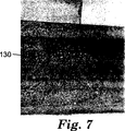
ロッカードラム試験の後、実施例4および比較例Bの研磨体を目視検査した。比較例B上の摩耗線は、実施例4上の摩耗線よりも著しく高輝度であった。摩耗線の輝度が高いほど、より多くの研磨粒子がロッカードラム試験中にサンプルから剥落したことを示している。サンプルの写真を倍率1.4で撮影した。図6および7は、それぞれ比較例Bおよび実施例4のディジタル画像である。各図中の摩耗線は130と記されている。
【0079】
ロッカードラム試験を用いて、実施例1〜3および比較例Aを1000サイクルで試験した。使用した加工品は、研磨体の表面に垂直に保持された0.1875インチ(0.476cm)角形鋼ロッドであった。8ポンド(3.63kg)の荷重をかけて、加工品を研磨体に押圧した。次に、10ポンド(4.54kg)の荷重をかけて、3000サイクルでロッカードラム試験を行った。得られたサンプルを倍率1.4で写真撮影した。
【0080】
摩耗線の顕微鏡観察により、サンプルの表面からダイヤモンドが除去された小さな領域を明確化した。摩耗線の輝度は、ダイヤモンドが剥落した後で金属が磨耗により平滑化されたことに起因するものであった。図8〜11は、それぞれ比較例Aおよび実施例1〜3のディジタル画像である。各図中の摩耗線は140と記されている。比較例A(図8)が最大の摩耗を示す。実施例1、2および3(それぞれ図9〜11)は、それぞれ、アルミニウムの添加量が増加するにつれて摩耗量が減少することを示している。
【0081】
試験手順2:ウォータージェット侵食試験:
高圧ウォータージェットを利用して実施例および比較例の研磨体からダイヤモンド研磨粒子を剥落させた。各サンプルから剥落した研磨粒子の数を、研磨体の焼結金属マトリックスと研磨粒子との接着性の尺度として使用した。
【0082】
高圧ウォータージェット装置は、商品名「RE 2000 NT CNC」としてRomero Engineering Inc.,Fort Worth,TXから市販されているウォータージェットを備えていた。このウォータージェットを、商品名「SV−IV Intensifier」としてInersoll−Rand Co.,Water Jet Systems,KSから市販されている増圧器に接続した。Jet Edge,Minneapolis,MNから市販されている4ノズル空気圧ロボットスイベルヘッドを介してサンプルに水を送出した。試験中、スイベルヘッドを約1800rpmで回転させた。ウォータージェット中を通過する水の流量は、44,000psi(303Mpa)の圧力で毎分約1ガロンであった。
【0083】
各サンプルを横切ってウォータージェットを2回パスさせた。パス中、スイベルヘッドをサンプルの表面から2.5インチ(6.35cm)に位置づけた。各パス中、ウォータージェットによりサンプル上の幅約1インチ(2.54cm)の領域を洗浄した。2回目のパスは、1回目のパスによって洗浄されなかったサンプル領域上に行った。サンプルを横切る1回目のパスは、毎分50インチ(127cm/分)で行われ、実質的な数のダイヤモンド研磨粒子の剥落は起こらなかった。2回目のパスは、毎分15インチ(38.1cm/分)の速度でおこなった。このパスにより、実質的な数のダイヤモンド研磨粒子が研磨体から剥落した。商品名「NIKON SMZ−2T STEREO−ZOOM」として市販されている顕微鏡を用いて、サンプル表面の写真を撮影した。
【0084】
10〜63倍の範囲の倍率を有する顕微鏡を用いてサンプルの目視検査を行うことにより、水流によって剥落したダイヤモンド研磨粒子の数を測定した。各サンプルの表面の写真を一定の倍率で撮影し、写真中のダイヤモンド研磨粒子の数を数えた。サンプル中に最初に存在していたダイヤモンド研磨粒子の正方形配列を用いて、サンプル間のダイヤモンド研磨粒子数の比較を行うことが可能であった。結果を表4に報告する。
【0085】
【表4】
表4
本明細書中に開示されている特許および特許出願は、個別に組み入れられたときと同じように参照により本明細書に組み入れるものとする。以上の説明は例示を目的とするものであって限定を意図したものではないことを理解しなければならない。本発明の種々の修正態様および変更態様は、本発明の範囲および精神から逸脱することなく以上の説明から当業者には自明なものとなるであろう。また、本発明は本明細書に記載の例示的実施形態に過度に限定されるべきものではないことを理解しなければならない。
【図面の簡単な説明】
【図1】 切削工具もしくは研削工具のセグメントの形態の本発明の融合金属マトリックス研磨体の斜視図である。
【図1A】 切断線1Aで得られた図1の融合金属マトリックス研磨体の断面図である。
【図2】 切削工具もしくは研削工具のセグメントの形態の本発明の融合金属マトリックス研磨体の斜視図である。
【図2A】 切断線2Aで得られた図2の融合金属マトリックス研磨体の断面図である。
【図3】 エリンガム図である。
【図4】 本発明の融合金属マトリックス研磨体の断面分解図である。
【図5】 本発明の研削ホイールの斜視図である。
【図6】 ロッカードラム試験に付された後の融合金属マトリックス研磨体の表面のディジタル画像である。
【図7】 ロッカードラム試験に付された後の本発明の融合金属マトリックス研磨体の表面のディジタル画像である。
【図8】 ロッカードラム試験に付された後の融合金属マトリックス研磨体の表面のディジタル画像である。
【図9】 ロッカードラム試験に付された後の本発明の融合金属マトリックス研磨体の表面のディジタル画像である。
【図10】 ロッカードラム試験に付された後の本発明の融合金属マトリックス研磨体の表面のディジタル画像である。
【図11】 ロッカードラム試験に付された後の本発明の融合金属マトリックス研磨体の表面のディジタル画像である。[0001]
background
The present invention relates to a fused metal bond abrasive bodies and a method for manufacturing the same.
[0002]
It is known to use metal matrices to retain superabrasive particles (eg, diamond and cubic boron nitride) in an abrasive body. Such a metal matrix abrasive can be used in a grinding wheel such as a pencil edge type wheel. Ideally, the bond between the metal matrix and the abrasive particles should be strong enough to hold the abrasive particles in the matrix when the abrasive particles are polishing the workpiece.
[0003]
It is also known that metal coatings can be used to improve the retention of abrasive particles in such metal matrices. For example, diamond abrasive particles may be advantageously coated with a carbide-forming metal that chemically bonds to the surface of diamond by formation of metal carbide. The metal coating can impart a texture to the surface of diamond or cubic boron nitride abrasive particles that are typically smooth and difficult to bond. A textured surface may allow the coated abrasive particles to be held more firmly in the metal matrix by mechanical adhesion. Suitable metals for adhesion promoting coatings include, for example, molybdenum, titanium, and chromium. These metals can be applied by a high temperature salt method or a vapor deposition method.
[0004]
Typically, the metal matrix abrasive is formed by a fusion process. Fusion processes are well known and include, for example, sintering, brazing, melting, impregnation or combinations thereof. In order to form a metal matrix abrasive, a fusible composition, typically containing metal powder and abrasive particles, is given a sufficient amount of time to unite the metal powder particles so that they are bonded together. Heated to a temperature of For example, fusion by a sintering process is typically performed in an air atmosphere at a relatively high temperature, for example, 700-1100 ° C. and high pressure. Under such conditions, oxidation of various components of the sinterable composition can occur. It has been found that the adhesion promoting function of the coating can be degraded when a very thin adhesion promoting coating on the abrasive particles is oxidized. Accordingly, materials and techniques have been developed to reduce or avoid oxidation.
[0005]
One way in which oxidation is minimized is to coat an oxidation resistant layer over the adhesion promoting coating. However, this method increases the cost of abrasive particles because it must be coated with at least two materials. In addition, the outer coating may not adhere well to the adhesion promoting coating, which may weaken the boundary between the abrasive particles and the metal matrix. U.S. Pat. No. 5,024,860 reports the use of a layer forming a chromium, titanium or zirconium carbide as part of a multilayer coating on diamond particles to improve retention in the matrix. . Two carbide forming layers are applied: a first thin base layer and a second thick oxidation resistant layer. This thick multilayer structure provides increased oxidation resistance over a thinner single coating.
[0006]
Further, there is a possibility that oxidation can be minimized by performing fusion (for example, sintering) in a non-oxidizing atmosphere such as a nitrogen atmosphere or under a very low air pressure. However, this type of process is undesirable because of the increased cost and process complexity associated with providing a non-oxidizing atmosphere. In particular, fusion in a non-oxidizing atmosphere is typically performed using an expensive vacuum furnace. In addition, the management of the non-oxidizing atmosphere is further complicated when the fusible composition contains organic compounds (eg, binders) that are burned off during the fusing process. Another method that can minimize oxidation is to remove and clean metal oxide contaminants from the metal powder prior to fusing the powder. This cleaning method adds additional processing steps and associated costs.
[0007]
While the above method can be used to reduce oxidation of the adhesion promoting coating on the abrasive particles, what is desired here is less than reducing oxidation of the adhesion promoting metal coating on the abrasive particles contained in the fused abrasive. It is a convenient way.
[0008]
Overview
The present invention provides a fused abrasive body comprising a plurality of metal-coated abrasive particles joined together by a metal matrix. Each metal coated abrasive particle includes an abrasive particle having an outer adhesion promoting metal coating. The fused abrasive also includes at least an effective amount of oxygen scavenger metal. Suitable oxygen scavenger metals are selected to be competitively oxidized against the metal coating on the abrasive particles. In this way, the metal-coated abrasive particles are protected from oxidation because the oxygen present during the fusion of the abrasive bodies at least partially reacts with the oxygen scavenger metal. As a result, oxidation of the adhesion promoting coating on the abrasive particles is at least reduced and preferably avoided. A suitable oxygen scavenger metal can be selected using an Ellingham diagram that predicts at a given fusion temperature whether a given metal will be competitively oxidized relative to the metal comprising the adhesion promoting coating on the abrasive particles. .
[0009]
As used herein, the term “competitively oxidizes” refers to a rate at least equal to the rate at which the metal comprising the adhesion promoting coating on the abrasive particles reacts with oxygen, preferably faster. This means that the oxygen scavenger metal reacts with oxygen. More specifically, with respect to the Ellingham diagram, a suitable oxygen scavenger metal is (1) an oxygen content that is lower than or equal to the oxygen partial pressure provided at the fusion temperature by the metal comprising the adhesion promoting coating on the abrasive particles. Provide pressure at the fusion temperature, or (2) fuse the Gibbs free energy of oxidation below or equal to the Gibbs free energy of oxidation provided at the fusion temperature by the metal comprising the adhesion promoting coating on the abrasive particles Provide at temperature.
[0010]
Thus, in a preferred embodiment of the invention, the oxygen scavenger metal has an oxygen partial pressure at the fusion temperature that is lower than or equal to the oxygen partial pressure provided at the fusion temperature by the metal comprising the adhesion promoting coating on the abrasive particles. provide.
[0011]
In another preferred embodiment of the present invention, the oxygen scavenger metal is an oxidation Gibbs free energy that is lower than or equal to the oxidation Gibbs free energy provided at the fusion temperature by the metal comprising the adhesion promoting coating on the abrasive particles. At the fusion temperature.
[0012]
In yet another preferred embodiment of the invention, the abrasive particles comprise diamond, cubic boron nitride, and the outer adhesion promoting coating on the abrasive particles comprises titanium, chromium, or an alloy thereof.
[0013]
In yet another preferred embodiment of the present invention, the oxygen scavenger metal comprises aluminum, calcium, magnesium, zirconium or combinations thereof and is present in the fusible composition in an amount ranging from about 0.1 to 10% by weight. To do.
[0014]
In the fused abrasive body of the present invention, the abrasive particles can be randomly or non-randomly distributed throughout the fused metal matrix. When distributed non-randomly, the abrasive particles can be concentrated in a fused metal matrix in a substantially parallel planar layer of abrasive particles.
[0015]
The metal matrix abrasive body of the present invention is particularly suitable for use in cutting wheels and grinding wheels. Accordingly, in still another preferred embodiment of the present invention, there is provided a cutting wheel or grinding wheel comprising at least one metal matrix abrasive of the present invention.
[0016]
The present invention also provides a method for producing the above fused metal matrix abrasive. This method includes
(A) a plurality of metal-coated abrasive particles;
Binding metal powder,
An effective amount of oxygen scavenger metal powder;
Providing a fusible composition comprising:
(B) fusing the fusible composition of step (a) by sintering, brazing, melting or impregnating the fusible composition;
Is included.
[0017]
As used herein, the following terms have the following meanings.
[0018]
“Fusion” is a term that describes a process in which metal particles, such as metal powders, are bonded together by the application of heat. Fusion of metal particles can be achieved by methods such as sintering, brazing, melting, impregnation or combinations thereof. The fusion of the metal particles can be performed at a temperature above or below the melting point of the metal powder to be fused, and may include applying pressure to the fusible composition.
[0019]
“Fusibility” is a term that describes a composition that can be fused.
[0020]
“Sintering” is a term that expresses the bonding of metal particles by a solid-phase reaction at a temperature lower than that required for forming a liquid phase. The fusible composition of the present invention typically has a temperature in the range of about 700-1100 ° C. and about 100-500 kg / cm.2Sintered at a pressure in the range of
[0021]
“Brazing” is a term that describes the process of bonding metal particles using a material that has a lower melting point than the metal particles to be joined.
[0022]
“Melting” is a term that describes the process of bonding metal particles together by converting the metal particles from a solid to a liquid by the application of heat.
[0023]
“Impregnation” is a term that describes a process in which a liquid substance enters a solid pore.
[0024]
In a preferred embodiment of the invention, the oxygen scavenger metal is added to the fusible composition in the form of a substantially pure metal. Substantially pure means at least 50% or more oxygen scavenger metal, more preferably 80% or more oxygen scavenger metal, even more preferably 95% or more oxygen scavenger metal, most preferably 99% or more. It means adding an oxygen scavenger metal to the fusible composition in a form comprising an oxygen scavenger metal.
[0025]
In another preferred embodiment of the invention, the fusible composition further contains a binder, most preferably a polymeric material such as polyvinyl butyral.
[0026]
In still another preferred embodiment of the present invention, the binding metal powder and the oxygen scavenger metal powder are provided in the form of a sheet-like binder layer having a first major surface and a second major surface. Prior to fusing, the abrasive particles are distributed on at least one major surface of the binder layer to form a fusible composition. The abrasive particles can be distributed in a non-random arrangement on the major surface of the binder layer.
[0027]
In yet another preferred embodiment of the present invention, the following method:
(A) providing a binder layer in the form of a sheet containing a metal powder, an effective amount of an oxygen scavenger metal, and a binder;
(B) providing a porous sheet material having a first main surface, a second main surface, and a plurality of openings extending from the first main surface to the second main surface;
(C) adhering an adhesive tape to one main surface of the porous sheet material;
(D) positioning metal-coated abrasive particles in at least some of the openings in the porous material to form an assembly;
(E) placing the assembly of step (d) in contact with at least one major surface of the binder layer of step (a) to form a fusible composition;
A fusible composition is produced according to a method comprising:
[0028]
In a preferred embodiment of this method, the fusogenic composition comprising two or more essentially parallel planar layers of metal-coated abrasive particles by stacking the fusible composition of step (e) together in 2 to 10,000 layers. A composition is produced. The fusible composition is then fused to provide an abrasive body comprising two or more essentially parallel planar layers of metal-coated abrasive particles.
[0029]
Detailed description
The present invention provides a fused metal matrix abrasive with improved abrasive particle retention. In particular, the present invention provides a fused metal matrix abrasive body comprising a plurality of metal-coated abrasive particles distributed throughout the metal matrix. Each metal coated abrasive particle contains an abrasive particle having an outer adhesion promoting metal coating. The metal matrix contains a binding metal and at least an effective amount of an oxygen scavenger metal. The oxygen scavenger metal serves to reduce or avoid oxidation of the adhesion promoting coating by reacting with oxygen present during the fusion process.
[0030]
Next, FIG. 1 will be described. This figure shows a perspective view of an embodiment of the fused
[0031]
Next, FIG. 2 will be described. This figure shows a perspective view of an embodiment of the sintered
[0032]
Abrasive particles
Abrasive particles suitable for use in the fused abrasive body of the present invention have at least one adhesion promoting coating containing a metal or metal alloy. The metal coating serves to increase the adhesion between the abrasive particles and the metal matrix. In the case of diamond abrasive particles, the metal adhesion promoting coating typically contains a metal that can form a carbide with diamond. In this way, the metal adhesion promoting coating advantageously forms a chemical bond with the diamond abrasive particles. The metal coating may also serve to prevent chemical reaction between the metal matrix and the abrasive particles. Such chemical reactions can cause undesired graphitization of the diamond, resulting in a decrease in diamond hardness, strength and wear resistance. Suitable carbide forming metals include, for example, molybdenum, titanium and chromium. The metal coating typically has a thickness in the range of about 0.5-5 μm and can be applied to the abrasive particles using any suitable method, such as hot salt application or metal deposition.
[0033]
Suitable abrasive particles include any type of abrasive particles that can be coated with one or more metal coatings that impart improved adhesion to the metal matrix. Preferred abrasive particles include diamond particles and cubic boron nitride particles, although other types of abrasive particles are within the scope of the present invention. The abrasive particles can be any size useful for the fused abrasive body. Typically, the size of the abrasive particles is in the range of about 0.1 to 1000 μm, more preferably in the range of about 40 to 1000 μm, and most preferably in the range of about 60 to 700 μm. Preferred abrasive particles contain diamond having an outer adhesion promoting coating containing titanium. Such abrasive particles are commercially available from General Electric Co. under the trade name “MBS-960TI2.” (Worthington, OH) and from DeBeers. Diamond abrasive particles having an outer adhesion promoting coating containing chromium are also commercially available from General Electric under the trade designation “MBS-960CR2.”
[0034]
Metal matrix
The fused abrasive body of the present invention includes a metal matrix that functions to bond and integrate abrasive particles. The metal matrix contains at least one binding metal and at least one oxygen scavenger metal.
[0035]
Bonded metal
Suitable bonding metals for the fused abrasive body of the present invention include, for example, bronze, cobalt, tungsten, copper, iron, nickel, tin, chromium, or mixtures or alloys thereof. As another consideration, the specific composition of the bonding metal can be selected by those skilled in the art who are familiar with the intended use of the fused abrasive. For example, various bonding metals can be selected to provide the desired hardness, abrasion resistance, impact resistance, adhesion, etc. of the abrasive particles. In many grinding wheel applications, the binding metal contains primarily copper, iron, nickel, tin, chromium, and tungsten carbide, with minor amounts of boron, silica, cobalt, and phosphorus (eg, less than about 1% by weight each) ) Included. The bonded metal typically represents about 75-99% by volume of the fused abrasive body, more preferably about 75-85% by volume of the fused abrasive body.
[0036]
The binding metal is preferably formed from a metal powder or a mixture of metal powders that are fused to form an integrated metal matrix. The fusion of the metal powder can be performed using a sintering, brazing, melting or impregnation process. Preferably, the metal powder is fused using a sintering process, for example by heating at a temperature of about 700-1100C. Suitable metal powders are available from Lucas Milhaupt, Inc. (Cudacky, WI) and Wall Colomony Corp. (Madison, MI).
[0037]
Oxygen scavenger metal
The metal matrix also contains an effective amount of oxygen scavenger metal. The oxygen scavenger metal serves to capture at least a portion of any oxygen present during the sintering of the abrasive body. As used herein, the term “scavenger” means a substance added to a mixture to remove or inactivate unwanted substances. Oxygen scavenging is performed by an oxidation process in which the oxygen scavenger metal reacts with at least a portion of the oxygen present during the fusion of the fusible composition. When this reaction occurs, the oxygen scavenger metal is converted to an oxide. As an example, aluminum (Al) is oxygen (O2) To react with aluminum oxide (Al2O3) Can function as an oxygen scavenger metal.
[0038]
By reacting (ie, scavenging) with oxygen present during the sintering of the abrasive body, the oxygen scavenger metal serves to protect the adhesion promoting coating on the abrasive particles from oxidation. Protection does not mean that the oxygen scavenger metal interacts or reacts directly with the adhesion promoting metal coating on the abrasive particles. More precisely, the oxygen scavenger metal functions as a sacrificial oxidant or oxygen “getter”. At least a portion of the oxygen present during the fusion process is trapped by the oxygen scavenger metal and therefore does not react (ie oxidize) with the adhesion promoting metal coating on the abrasive particles. Compared to adhesion promoting metal coatings on abrasive particles, suitable oxygen scavenger metals oxidize competitively. As defined above, the term “competitive oxidation” means that the oxygen scavenger metal is at a rate that is at least equal to, preferably faster than, the rate at which the metal comprising the adhesion promoting coating on the abrasive particles reacts with oxygen. Reacts with oxygen.
[0039]
When selecting a suitable oxygen scavenger metal for a particular fused abrasive body, using an Ellingham diagram may facilitate the selection. The Ellingham diagram shows the partial pressure of oxygen present in equilibrium with a given metal at a given temperature (hereinafter pO2) Can be used to predict. FIG. 3 shows an Ellingham diagram. The Ellingham diagram is also shown by David R. It can also be found in FIG. 10.13 of Gaskell, Introduction to the Metallurgical Thermodynamics, 2nd Edition, McGraw-Hill Book Co, page 287. This Ellingham diagram is incorporated herein by reference.
[0040]
Next, FIG. 3 will be described. In this figure, the Ellingham diagram is shown. The Ellingham diagram contains “Ellingham lines” for several metal oxidation reactions. For example, the Ellingham line for the oxidation of aluminum is the
[0041]
Using the procedure outlined above, a suitable oxygen scavenger metal for the fused abrasive body of the present invention is an equilibrium pO provided at the fusing temperature by the metal comprising the outer adhesion promoting coating of the abrasive particles.2Equilibrium pO less than or equal to2At the fusion temperature. Suitable oxygen scavenger metals are competitively oxidized against the metals that make up the adhesion promoting coating on the abrasive particles. As an example, using the Ellingham diagram of FIG. 3 at a temperature of 800 ° C., pO in equilibrium with titanium.2Is about 10-36Barometric pressure (10-34kPa). For aluminum at 800 ° C, the equilibrium pO2Is about 10-42Barometric pressure (10-40kPa). PO in equilibrium with aluminum2Is in equilibrium with titanium2Therefore, aluminum is a preferred oxygen scavenging metal when using titanium as an adhesion promoting metal coating on abrasive particles for abrasive bodies fused at 800 ° C. Oxygen scavenging metals that can be used when using titanium as an adhesion promoting coating on the abrasive particles include, for example, aluminum, calcium, magnesium and titanium and mixtures thereof. With the exception of titanium, the Ellingham line for these materials appears below the line for titanium on the Ellingham diagram.
[0042]
Another way to predict the preferred oxygen scavenger metal suitable for use with a given adhesion promoting coating is to give the Gibbs free energy of oxidation at fusion conditions for both the oxygen scavenger metal and the metal comprising the adhesion promoting coating. Thereafter, ΔGoxid). The preferred oxygen scavenger metal is the ΔG of the metal that forms the adhesion promoting coating on the abrasive particles under the same conditions.oxidΔG less than or equal tooxidWould have in fusion conditions.
[0043]
Next, it demonstrates using FIG. ΔG for the target metal oxidation reaction at the target temperatureoxidCan be determined from the Ellingham diagram. First, the position of the intersection of the vertical line corresponding to the temperature of the object and the Ellingham line for the metal oxidation reaction of the object is determined on the figure. Then, until it intersects the y axis, parallel to draw a horizontal line to the x-axis from this point. This intersection is the ΔG for the target metal oxidation reaction at the target temperature.oxidbe equivalent to.
[0044]
ΔG for useful oxygen scavenger metals and adhesion promoting coatingsoxidAnd pO2Are summarized in Table 1 as values at a pressure of 1 atmosphere (101.325 kPa) and a temperature of 950 ° C.
[0045]
[Table 1]
Table 1
[0046]
As shown in the Ellingham diagram and Table 1, when titanium is selected as the adhesion promoting metal coating on the abrasive particles, suitable oxygen scavenger metals include, for example, aluminum, calcium, magnesium and titanium. Also, when chromium is selected as the adhesion promoting metal coating on the abrasive particles, suitable oxygen scavenger metals include, for example, aluminum, calcium, magnesium, manganese, silicon and titanium.
[0047]
It must be added an effective amount of oxygen scavenger metal fusogenic composition. As used herein, the expression “effective amount” refers to an improved retention of abrasive particles in the metal matrix of the abrasive body as measured by at least one of the test procedures described herein. It refers to the amount of oxygen scavenger metal that is required in a particular fusogenic composition to provide. It is believed that the effective amount of oxygen scavenger metal can vary from fusogenic composition to fusogenic composition. For example, the effective amount includes the physical and compositional form of the oxygen scavenging metal, the amount of oxygen present in the atmosphere during fusion, the fusion temperature, the amount of oxygen present in the material comprising the fusible composition, the oxygen scavenger It may depend on factors such as the melting point of the metal and the shape and form of the abrasive to be fused. However, it is not limited to the factor described here. For example, if the oxygen scavenger metal can adversely affect the physical properties of the resulting sintered abrasive body, the addition of an oxygen scavenger metal in excess of an effective amount may be undesirable. For example, a high aluminum content (eg, greater than about 10% by weight) may make the abrasive body too soft for some polishing applications. Typically, the oxygen scavenger metal comprises about 0.1-10% by weight of the fusible composition, more preferably about 0.25-5% by weight of the fusible composition, and most preferably fusogenic. It will comprise about 0.5-2% by weight of the composition.
[0048]
Preferably, the oxygen scavenging metal will be provided in a physical form of fine metal powder and will be uniformly distributed throughout the fusible composition. When provided in the form of a uniformly dispersed fine metal powder, the oxygen scavenger metal is present throughout the fusible composition and can react with oxygen that may be present throughout the fusible composition. The kinetic (ie diffusion) inhibition of the reaction of oxygen with the oxygen scavenger metal will be minimized. Furthermore, the surface area of the metal powder per unit mass will typically increase with decreasing particle size. The greater the surface area, the more reactive the oxygen scavenger metal. Accordingly, preferred metal powders for oxygen scavenger metals have a particle size in the range of about 5-200 μm, more preferably in the range of about 15-120 μm.
[0049]
The compositional form of the oxygen scavenger metal can also affect the effective amount of metal required for a particular fusogenic composition. Preferably, the oxygen scavenger metal will be incorporated into the fusible composition in the form of a substantially pure metal rather than an alloy or the like. Thermodynamically, the chemical activity of the oxygen scavenger metal will be approximately equal to the mole fraction of oxygen scavenger metal in the alloy. Thus, an oxygen scavenger metal alloy that is in the form of an alloy with another metal that is not an oxygen scavenger metal (or is a less effective oxygen scavenger metal) is a form in which the oxygen scavenger metal is substantially pure (ie, non-alloyed). Will be less effective than if supplied in Also, the reaction rate of the oxygen scavenger metal will be limited by the diffusion rate of the oxygen scavenger metal through the alloy. If diffusion inhibition occurs, the efficiency of oxygen scavenging by the oxygen scavenger metal may be reduced, and as a result, oxidation of the adhesion promoting coating on the abrasive particles may be promoted. Substantially pure means at least about 50% or more oxygen scavenger metal, more preferably about 80% or more oxygen scavenger metal, most preferably about 95% or more oxygen scavenger metal, most particularly preferably 99% by weight. It means that the oxygen scavenger metal is added to the fusible composition in a form comprising more than% oxygen scavenger metal. Furthermore, it is preferred that the oxygen scavenger metal is not substantially contaminated with non-metals such as sulfur or oxygen. Substantially non-contaminated with non-metals means that the non-metallic contaminants that can form a reaction product with the oxygen scavenger metal are in a lower stoichiometric amount, preferably the reaction product with the oxygen scavenger metal. It means that the oxygen scavenger metal is provided in a form containing a non-metallic contaminant that can form in a stoichiometric amount of less than 10%. It will be appreciated that for some oxygen scavenger metals such as aluminum, the surface of the oxygen scavenger metal may be oxidized with an impermeable oxide layer that interferes with the oxidation of the metal surface.
[0050]
The melting point can also affect the effective amount of oxygen scavenger metal required for a particular fusogenic composition. Preferably, the melting point of the oxygen scavenger metal is a temperature lower than the fusion temperature. This would allow the oxygen scavenger metal to melt and flow throughout the fusible composition, resulting in more efficient capture of oxygen present during the fusing process.
[0051]
It will be appreciated that even in the presence of oxygen scavenging metals, oxidation of the adhesion promoting coating on the abrasive particles may not be completely avoided and typically is not completely avoided. More precisely, an effective amount of oxygen scavenger metal reduces the substantial oxidation of the adhesion promoting coating on the abrasive particles so that the adhesion between the abrasive particles and the metal matrix is increased over that in the absence of oxygen scavenger metal. It works to prevent.
[0052]
Fusing composition and method for producing a fused abrasive
In one embodiment of the fused abrasive body of the present invention, the abrasive particles are randomly distributed throughout the matrix. To produce such an abrasive body, first, a metal powder, a plurality of metal-coated abrasive particles, an effective amount of oxygen scavenger metal and any desired optional components (eg, organic binder, hard particles (eg, producing fusion composition by combining the tungsten carbide particles)). Examples of the organic binder include polymers such as polyvinyl butyral. The organic binder is incorporated into the fusible composition to produce a shaped mass known as a green body that can be physically handled by integrating the metal powder. Preferably, the organic binder is incorporated into the fusible composition in the minimum amount necessary to provide the desired properties due to the fact that the organic binder must be burned off during the fusing process. Optionally, hard particles such as tungsten carbide may be added to the fusible composition in order to increase the wear resistance of the resulting fused abrasive body. Typically, the hard particles are added in an amount in the range of about 10-50% by weight of the fusible composition, although amounts outside this range may be advantageous in some compositions. The organic solvent may be added to the fusible composition in an amount necessary to solvate the organic binder. A typical organic solvent includes, for example, methyl ethyl ketone. The organic solvent is added to the fusible composition in the minimum amount necessary to solvate the binder.
[0053]
After producing the fusible composition, it is then cold compressed in a mold using a press to form a green compact. Then, the green compact is fused. Fusion can be performed by sintering, brazing, melting and / or impregnating the fusible composition. In a preferred embodiment of the invention, the fusible composition is sintered. Sintering temperatures are typically in the range of about 700-1100 ° C. and typical sintering times are in the range of about 5-30 minutes. Pressure may be applied during the sintering process. Typical sintering pressure is about 100-500 kg / cm2Range. After the fusion, the obtained fused abrasive body can be cut into a desired size and shape.
[0054]
In other embodiments of the fused abrasive body of the present invention, the abrasive particles are non-randomly distributed throughout the metal matrix. For example, the abrasive particles may be one or more substantially planar layers concentrated in a metal matrix. Such sintered abrasive bodies may be formed, for example, by the method reported in US Pat. No. 5,380,390 (Tselesin).
[0055]
For a method of making an abrasive body having a substantially parallel planar layer of abrasive particles (see, eg, FIG. 2), see US patent application Ser. No. 08 / 882,434 entitled “Super Abrasive Cutting Surface”. Filed on June 25, 1997). FIG. 4 is an exploded cross-sectional view of the
[0056]
After the abrasive particles are received in the adhesive layer, the porous layer may be separated or removed from the adhesive layer. For the use of adhesive substrates to hold abrasive particles used in the sintering process, see US Pat. No. 5,380,390 (Tselesin) and US Pat. No. 5,620,489 (Tselesin) and US This is disclosed in Japanese Patent Application No. 08 / 728,169 (filed Oct. 9, 1996).
[0057]
[0058]
When performing the manufacturing process described above, the binder that makes up the binder layers 62, 64, and 66 may be any material that can be sintered together with the abrasive particle layers 82, 84, and 86. Preferably, the binder layers 62, 64 and 66 are soft and easily deformable flexible material (SEDF). Methods for producing SEDF are known in the art and are reported in US Pat. No. 5,620,489. Such SEDF can be produced by forming a paste or slurry containing a metal binding material (eg, a metal powder or mixture of metal powders), a binder, a solvent, a thinner and a plasticizer. Preferably, the oxygen scavenger metal is incorporated into the paste or slurry, but an oxygen scavenger metal may be provided between the
[0059]
The slurry is cast on a carrier sheet such as a release agent coated polyester film using a coating device such as a knife coater. The cast slurry is then solidified or cured at room temperature or with heat to evaporate volatile components (eg, organic solvents) from the slurry. A portion of the solvent will be dry removed after coating and the remaining organic compounds will be burned off during the sintering process. In addition, it should be noted that not all the bonding layers 62, 64, and 66 have the same composition.
[0060]
As long as the material is substantially porous (ie, about 30% to 99.5% porosity) and preferably has a plurality of non-randomly spaced openings, the porous material is virtually any It may be a material. Suitable materials are organic or metal nonwoven or woven mesh materials, specifically copper, bronze, zinc, steel, or nickel wire mesh or fiber mesh (eg, carbon or graphite). . Particularly suitable for use in the present invention are stainless steel wire mesh, expanded metal materials, and low melting temperature mesh type organic materials. In the embodiment shown in FIG. 4, the mesh is formed from a first set of parallel wires perpendicularly intersecting the second set of parallel wires to form
[0061]
Adhesive layers 92, 94 and 96 may be formed from a material having adhesive properties sufficient to hold abrasive particles at least temporarily, for example, a flexible substrate having a pressure sensitive adhesive on the surface. it can. Such substrates with adhesives are well known in the art. The adhesive must be able to hold the abrasive particles during manufacture and preferably must be burned off so that no ash remains during the sintering step. An example of an adhesive that can be used is a pressure sensitive adhesive commonly referred to as Book Tape # 895 (commercially available from Minnesota Mining and Manufacturing Company, St. Paul, MN).
[0062]
Fusion abrasive body of the present invention may be utilized in the cutting wheel and the grinding wheel. FIG. 5 will be described. This figure shows a perspective view of an embodiment of a cutting wheel or
[0063]
The outer
[0064]
Example
The present invention will be described more specifically with reference to the following examples, but is not limited to these examples. All parts, percentages, ratios, etc. in the examples are on a weight basis unless otherwise indicated.
[0065]
Commercial metal powders were mixed to provide the slurry composition shown in Table 2. The metal powder used to prepare the slurry has a median particle size of about 50 μm and is produced by Lucas Milhaupt, Inc. (Cudacky, WI) and Wall College Corp. (Madison, MI). Polyvinyl butyral is available from Solutia Inc. (St. Louis, MO) and the product name “BUTVAR B-76”. Santicizer 160 is a product of Solutia Inc. (St.Louis, MO) were those which are commercially available from.
[0066]
[Table 2]
Table 2
Examples 1-3:
In Examples 1-3, changes were made to the reference slurry compositions shown in Table 3 by adding the various amounts of aluminum powder shown below.
Slurry 1: 0.25 wt% aluminum powder based on the total weight of the slurry excluding organic matter.
Slurry 2: 0.50 wt% aluminum powder based on the total weight of the slurry excluding organic matter.
Slurry 3: 1 wt% aluminum powder based on the total weight of the slurry excluding organic matter.
Slurry A: Aluminum powder was not added.
[0068]
The aluminum powder used was commercially available from Fisher Scientific Company (Fair Lawn, New Jersey) under the trade name “ALUMINUM METAL, FINEST POWDER, A-559”. In order to control the thickness of the tape, slurries 1 to 3 and slurry A were cast using a knife coater to form a metal tape. The slurry was cast on a polyester release liner. The final surface density of the metal tape after solvent evaporation is about 0.75 grams / inch.2(0.116 grams / cm2)Met.
[0069]
A diamond / tape laminate layer was prepared by first bonding a pressure sensitive adhesive tape to one side of a stainless steel mesh. The stainless steel mesh had about 165 wires per inch (65 wires per cm) and was made of 0.019 inch (0.483 mm) wire. The adhesive tape is available from the Minnesota Mining and Manufacturing Company, St. It was commercially available from Paul, MN. The diamond abrasive particles were dropped onto the wire mesh so that each diamond filled each hole in the mesh and adhered to the adhesive surface of the tape. The abrasive particles contained diamond with an outer coating of titanium about 1 μm thick. Diamond abrasive particles have a size of about 170/200 US standard mesh and are sold under the name of General Electric Co. under the trade designation “MBG-640TI”. , Worthington, Ohio. More than one diamond abrasive particle per screen opening was removed.
[0070]
After bonding the diamond to the adhesive tape, the wire mesh was peeled off from the tape, leaving the diamond bonded to the tape in a square array. The diamond / tape laminate layer was then placed in contact with the major surface of the cast metal tape layer. The other major surface of the cast metal tape was placed in contact with a 0.010 inch (0.254 mm) thick copper metal layer. As a result, each sample had one diamond layer, one metal tape layer, and one copper metal layer.
[0071]
Comparative Example B and Example 4 were prepared by doping copper (II) oxide powder. The purpose of copper (II) oxide doping is to introduce oxygen into the composition prior to sintering in order to demonstrate the detrimental effect of oxygen on the adhesion of titanium coated diamond abrasive particles in a sintered metal matrix. there were.
[0072]
Comparative Example B:
Comparative Example B was produced by making the following changes to Comparative Example A. After producing a diamond / tape laminate in the same manner as in Comparative Example A, copper (II) oxide powder was sprayed on the laminate and adhered to the exposed adhesive surface of the tape. Excess powder was removed.
[0073]
Example 4:
Example 4 was prepared by making the following changes to Comparative Example A. After producing a diamond / tape laminate in the same manner as in Comparative Example A, a mixture of copper (II) oxide powder and aluminum powder was sprayed on the laminate. A mixture was made by subjecting 20 grams of aluminum to 108 grams of copper (II) oxide in a ball milling process. This mixture contained a stoichiometrically about 50% excess of aluminum over that required to reduce copper (II) oxide to copper. A mixture of copper (II) oxide powder and aluminum was adhered to the exposed adhesive surface on the tape. Excess powder was removed.
[0074]
Examples 1-4 and Comparative Examples AB were stacked on top of each other, with adjacent samples separated by a 0.25 inch (0.365 cm) thick graphite plate. Next, a stack containing 6 samples and a graphite spacer plate was placed in a hydraulic sintering press in an oven. The stack was then sintered in air according to the sintering profile shown in Table 3.
[0075]
[Table 3]
Table 3
Test procedure 1: Rocker drum test:
The sintered abrasive bodies of the examples and comparative examples were tested using a rocker drum tester designed to test abrasives under high pressure. The rocker tester was equipped with a motor driven
[0077]
Using the rocker drum test of Test Procedure 1, Example 4 and Comparative Example B were each tested at 1000 cycles. The work piece used was a 0.1875 inch (0.476 cm) square steel rod held perpendicular to the surface of the sample. The workpiece was pressed against the sample under a load of 8 pounds (3.63 kg). After the rocker drum test, there were observable wear lines on each surface of the abrasive sample.
[0078]
After rocker drum test it was visually inspected abrasive of Example 4 and Comparative Example B. The wear line on Comparative Example B was significantly brighter than the wear line on Example 4. Higher wear line brightness indicates that more abrasive particles were detached from the sample during the rocker drum test. A sample photograph was taken at a magnification of 1.4. 6 and 7 are digital images of Comparative Example B and Example 4, respectively. The wear line in each figure is marked 130.
[0079]
Examples 1-3 and Comparative Example A were tested at 1000 cycles using the rocker drum test. The work piece used was a 0.1875 inch square steel rod held perpendicular to the surface of the abrasive body. The workpiece was pressed against the abrasive body under a load of 8 pounds (3.63 kg). Next, a rocker drum test was performed in 3000 cycles under a load of 10 pounds (4.54 kg). The obtained sample was photographed at a magnification of 1.4.
[0080]
Microscopic observation of the wear line clarified a small area where diamond was removed from the surface of the sample. The brightness of the wear line was attributed to the fact that the metal was smoothed by abrasion after the diamond peeled off. 8 to 11 are digital images of Comparative Example A and Examples 1 to 3, respectively. The wear line in each figure is marked 140. Comparative Example A (FIG. 8) shows maximum wear. Examples 1, 2 and 3 (FIGS. 9-11, respectively) show that the amount of wear decreases as the amount of aluminum added increases.
[0081]
Test procedure 2: Water jet erosion test:
The diamond abrasive particles were peeled off from the abrasive bodies of Examples and Comparative Examples using a high-pressure water jet. The number of abrasive particles peeled from each sample was used as a measure of the adhesion between the sintered metal matrix of the abrasive and the abrasive particles.
[0082]
High pressure water jet device, Romero Engineering Inc. under the trade name "RE 2000 NT CNC" , It was equipped with a water jet, which is commercially available Fort Worth, from TX. This water jet is named “Insoll-Rand Co.” under the trade name “SV-IV Intensifier”. It was connected to a pressure intensifier which is commercially available Water Jet Systems, from KS. Water was delivered to the sample via a 4-nozzle pneumatic robot swivel head commercially available from Jet Edge, Minneapolis, MN. During the test, the swivel head was rotated at about 1800 rpm. The flow rate of water passing through the water jet was about 1 gallon per minute at a pressure of 44,000 psi (303 Mpa).
[0083]
Two water jets were passed across each sample. In the path, and positioned 2.5 inches swivel head from the surface of the sample (6.35 cm). During each pass, an area about 1 inch (2.54 cm) wide on the sample was washed with a water jet. Second pass was carried out first sample area on which have not been cleaned by the path. The first pass across the sample was performed at 50 inches per minute (127 cm / min) and no substantial number of diamond abrasive particles were detached. The second pass was performed at a speed of 15 inches per minute (38.1 cm / min). This path substantial number of diamond abrasive grains is peel from the polishing body. A photograph of the sample surface was taken using a microscope marketed under the trade name “NIKON SMZ-2T STERREO-ZOOM”.
[0084]
By visually inspecting the sample using a microscope having a magnification in the range of 10 to 63 times, the number of diamond abrasive particles peeled off by the water flow was measured. A photograph of the surface of each sample was taken at a constant magnification, and the number of diamond abrasive particles in the photograph was counted. It was possible to make a comparison of the number of diamond abrasive particles between samples using the square array of diamond abrasive particles initially present in the sample. The results are reported in Table 4.
[0085]
[Table 4]
Table 4
The patents and patent applications disclosed herein are hereby incorporated by reference in the same way as if individually incorporated. It should be understood that the foregoing description is for purposes of illustration and is not intended to be limiting. Various modifications and alterations of this invention will become apparent to those skilled in the art from the foregoing description without departing from the scope and spirit of this invention. It should also be understood that the present invention should not be unduly limited to the exemplary embodiments described herein.
[Brief description of the drawings]
FIG. 1 is a perspective view of a fused metal matrix abrasive body of the present invention in the form of a segment of a cutting tool or grinding tool.
1A is a cross-sectional view of the fused metal matrix abrasive body of FIG. 1 taken at
FIG. 2 is a perspective view of the fused metal matrix abrasive body of the present invention in the form of a cutting tool or grinding tool segment.
2A is a cross-sectional view of the fused metal matrix abrasive body of FIG. 2 taken at
FIG. 3 is an Ellingham diagram.
FIG. 4 is an exploded cross-sectional view of the fused metal matrix abrasive of the present invention.
FIG. 5 is a perspective view of a grinding wheel of the present invention.
FIG. 6 is a digital image of the surface of a fused metal matrix abrasive body after being subjected to a rocker drum test.
FIG. 7 is a digital image of the surface of the fused metal matrix abrasive body of the present invention after being subjected to a rocker drum test.
FIG. 8 is a digital image of the surface of a fused metal matrix abrasive body after being subjected to a rocker drum test.
FIG. 9 is a digital image of the surface of the fused metal matrix abrasive body of the present invention after being subjected to a rocker drum test.
FIG. 10 is a digital image of the surface of the fused metal matrix abrasive body of the present invention after being subjected to a rocker drum test.
FIG. 11 is a digital image of the surface of the fused metal matrix abrasive body of the present invention after being subjected to a rocker drum test.
Claims (3)
該金属被覆研磨粒子のそれぞれが研磨粒子を含み、
該研磨粒子が、チタン、クロムおよびそれらの合金から選択される金属を含む外側接着促進コーティングを有し、
該融合金属マトリックスが、青銅、コバルト、タングステン、銅、鉄、ニッケル、クロムおよびそれらの混合物から選択される結合金属を含み、該融合金属マトリックスの0.1〜10重量%が、アルミニウム、カルシウム、マグネシウム、マンガン、ケイ素、チタン、ジルコニウムおよびそれらの組み合わせから選択される、酸素スカベンジャー金属の微粉末を含み、
該融合金属マトリックス中に該金属被覆研磨粒子を分布し、該融合金属マトリックスが該金属被覆研磨粒子と結合して一体化する、
融合金属マトリックス研磨体。 A fused metal matrix abrasive, the fused metal matrix abrasive comprising a plurality of metal-coated abrasive particles and a fused metal matrix;
Each of the metal-coated abrasive particles comprises abrasive particles;
The abrasive particles have an outer adhesion promoting coating comprising a metal selected from titanium, chromium and alloys thereof;
The fusion metal matrix comprises a binding metal selected from bronze, cobalt, tungsten, copper, iron, nickel, chromium and mixtures thereof, wherein 0.1 to 10% by weight of the fusion metal matrix comprises aluminum, calcium, Comprising a fine powder of oxygen scavenger metal selected from magnesium, manganese, silicon, titanium, zirconium and combinations thereof;
Distributing the metal-coated abrasive particles in the fused metal matrix, the fused metal matrix being combined and integrated with the metal-coated abrasive particles;
Fusion metal matrix polishing body.
(a) 融合性組成物を提供するステップ、および
(b) ステップ(a)の融合性組成物を焼結、鑞付け、溶融または含浸することによって、該融合性組成物を融合するステップ
を含み、
該融合性組成物が、
チタン、クロムおよびそれらの合金から選択される接着促進金属で被覆した複数の研磨粒子、および
青銅、コバルト、タングステン、銅、鉄、ニッケル、クロムおよびそれらの混合物から選択される結合金属の粉末
を含み、
該融合性組成物の0.1〜10重量%が、アルミニウム、カルシウム、マグネシウム、マンガン、ケイ素、チタン、ジルコニウムおよびそれらの組み合わせから選択される酸素スカベンジャー金属の微粉末を含む、方法。A method for producing a fused metal matrix abrasive according to claim 1, wherein the method comprises:
(A) providing a fusible composition ; and
(B) fusing the fusible composition by sintering, brazing, melting or impregnating the fusible composition of step (a).
Including
The fusogenic composition is
A plurality of abrasive particles coated with an adhesion promoting metal selected from titanium, chromium and their alloys; and
Bonded metal powder selected from bronze, cobalt, tungsten, copper, iron, nickel, chromium and mixtures thereof
Including
A method wherein 0.1 to 10% by weight of the fusible composition comprises a fine powder of oxygen scavenger metal selected from aluminum, calcium, magnesium, manganese, silicon, titanium, zirconium and combinations thereof .
Applications Claiming Priority (3)
| Application Number | Priority Date | Filing Date | Title |
|---|---|---|---|
| US09/405,466 US6416560B1 (en) | 1999-09-24 | 1999-09-24 | Fused abrasive bodies comprising an oxygen scavenger metal |
| US09/405,466 | 1999-09-24 | ||
| PCT/US2000/008787 WO2001023630A1 (en) | 1999-09-24 | 2000-04-03 | Fused abrasive bodies comprising an oxygen scavenger metal |
Publications (3)
| Publication Number | Publication Date |
|---|---|
| JP2003510193A JP2003510193A (en) | 2003-03-18 |
| JP2003510193A5 JP2003510193A5 (en) | 2007-05-31 |
| JP4611590B2 true JP4611590B2 (en) | 2011-01-12 |
Family
ID=23603817
Family Applications (1)
| Application Number | Title | Priority Date | Filing Date |
|---|---|---|---|
| JP2001527010A Expired - Fee Related JP4611590B2 (en) | 1999-09-24 | 2000-04-03 | Fused abrasive body containing oxygen scavenger metal |
Country Status (7)
| Country | Link |
|---|---|
| US (1) | US6416560B1 (en) |
| EP (1) | EP1218556B1 (en) |
| JP (1) | JP4611590B2 (en) |
| KR (1) | KR100769745B1 (en) |
| AU (1) | AU4064700A (en) |
| CA (1) | CA2388457C (en) |
| WO (1) | WO2001023630A1 (en) |
Families Citing this family (24)
| Publication number | Priority date | Publication date | Assignee | Title |
|---|---|---|---|---|
| US6575353B2 (en) * | 2001-02-20 | 2003-06-10 | 3M Innovative Properties Company | Reducing metals as a brazing flux |
| KR100472642B1 (en) * | 2003-03-15 | 2005-03-10 | 일진디스플레이(주) | Diamond particles for sintering tool and production method thereof and the sintering tool using the same |
| US7073496B2 (en) * | 2003-03-26 | 2006-07-11 | Saint-Gobain Abrasives, Inc. | High precision multi-grit slicing blade |
| US7350599B2 (en) | 2004-10-18 | 2008-04-01 | Smith International, Inc. | Impregnated diamond cutting structures |
| GB0426143D0 (en) * | 2004-11-26 | 2004-12-29 | Element Six Ltd | Rigid three-dimensional components |
| US7866419B2 (en) | 2006-07-19 | 2011-01-11 | Smith International, Inc. | Diamond impregnated bits using a novel cutting structure |
| EP2057244B1 (en) * | 2006-09-01 | 2010-05-12 | Cedric Sheridan | Intermediate product for use in the production of abrading or cutting tools |
| EP1923175A1 (en) * | 2006-11-15 | 2008-05-21 | Cedric Sheridan | Intermediate product for use in the production of abrading or cutting tools |
| WO2008097358A2 (en) * | 2006-09-12 | 2008-08-14 | Jamin Micarelli | Lightweight armor composite, method of making same, and articles containing the same |
| US8517125B2 (en) | 2007-05-18 | 2013-08-27 | Smith International, Inc. | Impregnated material with variable erosion properties for rock drilling |
| GB2450177B (en) * | 2007-05-18 | 2010-07-28 | Smith International | Impregnated material with variable erosion properties for rock drilling and the method to manufacture |
| US8894731B2 (en) * | 2007-10-01 | 2014-11-25 | Saint-Gobain Abrasives, Inc. | Abrasive processing of hard and /or brittle materials |
| US8882868B2 (en) * | 2008-07-02 | 2014-11-11 | Saint-Gobain Abrasives, Inc. | Abrasive slicing tool for electronics industry |
| WO2011049479A1 (en) * | 2009-10-21 | 2011-04-28 | Andrey Mikhailovich Abyzov | Composite material having high thermal conductivity and process of fabricating same |
| KR101264337B1 (en) | 2010-08-13 | 2013-05-14 | 삼성에스디아이 주식회사 | Positive active material and lithium battery using it |
| FR2979845B1 (en) * | 2011-09-09 | 2015-02-13 | Saint Gobain | FLAT GLASS FILLING WHEEL |
| GB201119329D0 (en) * | 2011-11-09 | 2011-12-21 | Element Six Ltd | Method of making cutter elements,cutter element and tools comprising same |
| WO2013191656A1 (en) * | 2012-06-20 | 2013-12-27 | Agency For Science, Technology And Research | A layer arrangement and a wafer level package comprising the layer arrangement |
| GB201215469D0 (en) * | 2012-08-30 | 2012-10-17 | Element Six Ltd | Diamond constructions, tools comprising same and method for making same |
| US9856702B2 (en) | 2013-09-18 | 2018-01-02 | Smith International, Inc. | Cutting element for a downhole tool |
| WO2016033080A1 (en) * | 2014-08-26 | 2016-03-03 | Nano Materials International Corporation | Aluminum diamond cutting tool |
| GB201701902D0 (en) * | 2017-02-06 | 2017-03-22 | Element Six Gmbh | Coated super hard particles and composite materials made from coated superhard particles |
| CN110337347B (en) * | 2017-02-28 | 2022-07-12 | 3M创新有限公司 | Metal bond abrasive article and method of making a metal bond abrasive article |
| CN109822452B (en) * | 2019-03-29 | 2020-04-03 | 深圳市宏通新材料有限公司 | Porous metal-based diamond grinding and polishing plate |
Family Cites Families (30)
| Publication number | Priority date | Publication date | Assignee | Title |
|---|---|---|---|---|
| GB516474A (en) | 1937-06-28 | 1940-01-03 | Carborundum Co | Improvements in or relating to metal bonded abrasive articles |
| US2746888A (en) | 1952-07-05 | 1956-05-22 | Du Pont | Method of forming titanium coating on refractory body |
| US3293012A (en) | 1962-11-27 | 1966-12-20 | Exxon Production Research Co | Process of infiltrating diamond particles with metallic binders |
| US3588992A (en) | 1967-06-16 | 1971-06-29 | Toyoda Machine Works Ltd | Manufacturing process for a metal bonded porous substance, particularly a tool made of said substance |
| US3650714A (en) | 1969-03-04 | 1972-03-21 | Permattach Diamond Tool Corp | A method of coating diamond particles with metal |
| US3850590A (en) * | 1970-09-28 | 1974-11-26 | Impregnated Diamond Prod Ltd | An abrasive tool comprising a continuous porous matrix of sintered metal infiltrated by a continuous synthetic resin |
| JPS5768287A (en) | 1980-10-16 | 1982-04-26 | Kobe Steel Ltd | Production of composite material |
| US4457113A (en) | 1982-02-24 | 1984-07-03 | Super-Cut, Inc. | Protected super-abrasive grinding tool |
| US4738689A (en) | 1984-03-20 | 1988-04-19 | General Electric Company | Coated oxidation-resistant porous abrasive compact and method for making same |
| US4874398A (en) | 1984-08-24 | 1989-10-17 | Ringwood Alfred E | Diamond compacts and process for making same |
| JPH01122908A (en) * | 1987-11-06 | 1989-05-16 | Showa Denko Kk | Method for coating surface of cubic boron nitride with metallic titanium |
| US5024680A (en) | 1988-11-07 | 1991-06-18 | Norton Company | Multiple metal coated superabrasive grit and methods for their manufacture |
| US4925457B1 (en) | 1989-01-30 | 1995-09-26 | Ultimate Abrasive Syst Inc | Method for making an abrasive tool |
| US5024860A (en) | 1989-05-24 | 1991-06-18 | Ethyl Corporation | Rocket motor insulation using phosphonitrilic elastomeric compositions |
| US5126207A (en) | 1990-07-20 | 1992-06-30 | Norton Company | Diamond having multiple coatings and methods for their manufacture |
| US5380390B1 (en) | 1991-06-10 | 1996-10-01 | Ultimate Abras Systems Inc | Patterned abrasive material and method |
| HUT62831A (en) | 1991-09-12 | 1993-06-28 | Gen Electric | Method for producing covered cubed leather-nitride abrasive grain, abrasive grain and grinding tool by using the same |
| JPH05177549A (en) * | 1991-10-07 | 1993-07-20 | Mitsubishi Materials Corp | Composite super-abrasive grain and manufacture of grinding wheel |
| US5250086A (en) | 1992-03-25 | 1993-10-05 | General Electric Company | Multi-layer metal coated diamond abrasives for sintered metal bonded tools |
| US5232469A (en) | 1992-03-25 | 1993-08-03 | General Electric Company | Multi-layer metal coated diamond abrasives with an electrolessly deposited metal layer |
| ZA941116B (en) * | 1993-03-05 | 1994-08-30 | Smith International | Polycrystalline diamond compact |
| US5346719A (en) | 1993-08-02 | 1994-09-13 | General Electric Company | Tungsten metallization of CVD diamond |
| ZA9410384B (en) | 1994-04-08 | 1996-02-01 | Ultimate Abrasive Syst Inc | Method for making powder preform and abrasive articles made therefrom |
| JP3866305B2 (en) | 1994-10-27 | 2007-01-10 | 住友電工ハードメタル株式会社 | Composite high hardness material for tools |
| US5697994A (en) | 1995-05-15 | 1997-12-16 | Smith International, Inc. | PCD or PCBN cutting tools for woodworking applications |
| US5725421A (en) | 1996-02-27 | 1998-03-10 | Minnesota Mining And Manufacturing Company | Apparatus for rotative abrading applications |
| CA2264858C (en) | 1996-09-04 | 2007-04-03 | Amic Industries Limited | Manufacture of a metal bonded abrasive product |
| JP3135517B2 (en) * | 1997-03-11 | 2001-02-19 | 愛知県 | Manufacturing method of superabrasive metal bond whetstone |
| US6039641A (en) | 1997-04-04 | 2000-03-21 | Sung; Chien-Min | Brazed diamond tools by infiltration |
| US6110031A (en) | 1997-06-25 | 2000-08-29 | 3M Innovative Properties Company | Superabrasive cutting surface |
-
1999
- 1999-09-24 US US09/405,466 patent/US6416560B1/en not_active Expired - Lifetime
-
2000
- 2000-04-03 WO PCT/US2000/008787 patent/WO2001023630A1/en not_active Application Discontinuation
- 2000-04-03 JP JP2001527010A patent/JP4611590B2/en not_active Expired - Fee Related
- 2000-04-03 KR KR1020027003769A patent/KR100769745B1/en not_active IP Right Cessation
- 2000-04-03 EP EP00920050A patent/EP1218556B1/en not_active Expired - Lifetime
- 2000-04-03 CA CA002388457A patent/CA2388457C/en not_active Expired - Fee Related
- 2000-04-03 AU AU40647/00A patent/AU4064700A/en not_active Abandoned
Also Published As
| Publication number | Publication date |
|---|---|
| CA2388457C (en) | 2008-10-21 |
| CA2388457A1 (en) | 2001-04-05 |
| EP1218556A1 (en) | 2002-07-03 |
| AU4064700A (en) | 2001-04-30 |
| JP2003510193A (en) | 2003-03-18 |
| US6416560B1 (en) | 2002-07-09 |
| KR20020034194A (en) | 2002-05-08 |
| WO2001023630A1 (en) | 2001-04-05 |
| KR100769745B1 (en) | 2007-10-23 |
| EP1218556B1 (en) | 2004-06-23 |
Similar Documents
| Publication | Publication Date | Title |
|---|---|---|
| JP4611590B2 (en) | Fused abrasive body containing oxygen scavenger metal | |
| JP2904799B2 (en) | Brazed thermostable polycrystalline diamond product and method of making same | |
| JP4000060B2 (en) | Abrasive article having optimally oriented abrasive particles and method for producing the same | |
| US3857744A (en) | Method for manufacturing composite articles containing boron carbide | |
| JP5285609B2 (en) | Abrasive article and method with extended life | |
| US6830598B1 (en) | Molten braze coated superabrasive particles and associated methods | |
| AU742758B2 (en) | Superabrasive wheel with active bond | |
| JP2843111B2 (en) | Abrasive material coated with refractory metal oxide, and a grinding wheel manufactured from the abrasive material | |
| CA2272258C (en) | Abrasive tool | |
| US4194040A (en) | Article of fibrillated polytetrafluoroethylene containing high volumes of particulate material and methods of making and using same | |
| CN1684801B (en) | Molten braze coated superabrasive particles and associated methods | |
| EP0272197B1 (en) | Silicon carbide abrasive particles having multilayered coating | |
| JP4115521B2 (en) | Method of coating, method of manufacturing ceramic-metal structure, bonding method, and structure formed by them | |
| RU2372371C2 (en) | Coated abrasives | |
| JPS62246466A (en) | Method of arranging grain of single layer on surface of article | |
| WO1998005466A1 (en) | Wear resistant bond for an abrasive tool | |
| JP2005131784A (en) | Rotary dressing tool containing brazed diamond layer | |
| JPS637912B2 (en) | ||
| JPH05104445A (en) | Manufacturing method for cutting cutter | |
| JPH04269170A (en) | Metal coated porous grinding wheel | |
| JP2565622B2 (en) | Grinding stone manufacturing method | |
| JPH01289668A (en) | Grinding element super-abrasive grain | |
| JPS61219574A (en) | Grindstone | |
| JPH1043911A (en) | Diamond-coated tungsten carbide cemented cutting tool whose artificial diamond coating film has high bond strength |
Legal Events
| Date | Code | Title | Description |
|---|---|---|---|
| A521 | Request for written amendment filed |
Free format text: JAPANESE INTERMEDIATE CODE: A523 Effective date: 20070329 |
|
| A621 | Written request for application examination |
Free format text: JAPANESE INTERMEDIATE CODE: A621 Effective date: 20070329 |
|
| A131 | Notification of reasons for refusal |
Free format text: JAPANESE INTERMEDIATE CODE: A131 Effective date: 20090818 |
|
| A521 | Request for written amendment filed |
Free format text: JAPANESE INTERMEDIATE CODE: A523 Effective date: 20091118 |
|
| A131 | Notification of reasons for refusal |
Free format text: JAPANESE INTERMEDIATE CODE: A131 Effective date: 20100427 |
|
| A601 | Written request for extension of time |
Free format text: JAPANESE INTERMEDIATE CODE: A601 Effective date: 20100726 |
|
| A602 | Written permission of extension of time |
Free format text: JAPANESE INTERMEDIATE CODE: A602 Effective date: 20100802 |
|
| A521 | Request for written amendment filed |
Free format text: JAPANESE INTERMEDIATE CODE: A523 Effective date: 20100813 |
|
| TRDD | Decision of grant or rejection written | ||
| A01 | Written decision to grant a patent or to grant a registration (utility model) |
Free format text: JAPANESE INTERMEDIATE CODE: A01 Effective date: 20101012 |
|
| A01 | Written decision to grant a patent or to grant a registration (utility model) |
Free format text: JAPANESE INTERMEDIATE CODE: A01 |
|
| A61 | First payment of annual fees (during grant procedure) |
Free format text: JAPANESE INTERMEDIATE CODE: A61 Effective date: 20101014 |
|
| FPAY | Renewal fee payment (event date is renewal date of database) |
Free format text: PAYMENT UNTIL: 20131022 Year of fee payment: 3 |
|
| R150 | Certificate of patent or registration of utility model |
Free format text: JAPANESE INTERMEDIATE CODE: R150 |
|
| LAPS | Cancellation because of no payment of annual fees |