JP5285609B2 - Abrasive article and method with extended life - Google Patents
Abrasive article and method with extended life Download PDFInfo
- Publication number
- JP5285609B2 JP5285609B2 JP2009526795A JP2009526795A JP5285609B2 JP 5285609 B2 JP5285609 B2 JP 5285609B2 JP 2009526795 A JP2009526795 A JP 2009526795A JP 2009526795 A JP2009526795 A JP 2009526795A JP 5285609 B2 JP5285609 B2 JP 5285609B2
- Authority
- JP
- Japan
- Prior art keywords
- foil
- abrasive
- abrasive particles
- alloy
- component
- Prior art date
- Legal status (The legal status is an assumption and is not a legal conclusion. Google has not performed a legal analysis and makes no representation as to the accuracy of the status listed.)
- Expired - Fee Related
Links
Images


Classifications
-
- B—PERFORMING OPERATIONS; TRANSPORTING
- B24—GRINDING; POLISHING
- B24D—TOOLS FOR GRINDING, BUFFING OR SHARPENING
- B24D3/00—Physical features of abrasive bodies, or sheets, e.g. abrasive surfaces of special nature; Abrasive bodies or sheets characterised by their constituents
- B24D3/02—Physical features of abrasive bodies, or sheets, e.g. abrasive surfaces of special nature; Abrasive bodies or sheets characterised by their constituents the constituent being used as bonding agent
- B24D3/04—Physical features of abrasive bodies, or sheets, e.g. abrasive surfaces of special nature; Abrasive bodies or sheets characterised by their constituents the constituent being used as bonding agent and being essentially inorganic
- B24D3/06—Physical features of abrasive bodies, or sheets, e.g. abrasive surfaces of special nature; Abrasive bodies or sheets characterised by their constituents the constituent being used as bonding agent and being essentially inorganic metallic or mixture of metals with ceramic materials, e.g. hard metals, "cermets", cements
- B24D3/08—Physical features of abrasive bodies, or sheets, e.g. abrasive surfaces of special nature; Abrasive bodies or sheets characterised by their constituents the constituent being used as bonding agent and being essentially inorganic metallic or mixture of metals with ceramic materials, e.g. hard metals, "cermets", cements for close-grained structure, e.g. using metal with low melting point
-
- B—PERFORMING OPERATIONS; TRANSPORTING
- B24—GRINDING; POLISHING
- B24D—TOOLS FOR GRINDING, BUFFING OR SHARPENING
- B24D3/00—Physical features of abrasive bodies, or sheets, e.g. abrasive surfaces of special nature; Abrasive bodies or sheets characterised by their constituents
- B24D3/02—Physical features of abrasive bodies, or sheets, e.g. abrasive surfaces of special nature; Abrasive bodies or sheets characterised by their constituents the constituent being used as bonding agent
- B24D3/04—Physical features of abrasive bodies, or sheets, e.g. abrasive surfaces of special nature; Abrasive bodies or sheets characterised by their constituents the constituent being used as bonding agent and being essentially inorganic
- B24D3/06—Physical features of abrasive bodies, or sheets, e.g. abrasive surfaces of special nature; Abrasive bodies or sheets characterised by their constituents the constituent being used as bonding agent and being essentially inorganic metallic or mixture of metals with ceramic materials, e.g. hard metals, "cermets", cements
- B24D3/10—Physical features of abrasive bodies, or sheets, e.g. abrasive surfaces of special nature; Abrasive bodies or sheets characterised by their constituents the constituent being used as bonding agent and being essentially inorganic metallic or mixture of metals with ceramic materials, e.g. hard metals, "cermets", cements for porous or cellular structure, e.g. for use with diamonds as abrasives
-
- B—PERFORMING OPERATIONS; TRANSPORTING
- B23—MACHINE TOOLS; METAL-WORKING NOT OTHERWISE PROVIDED FOR
- B23D—PLANING; SLOTTING; SHEARING; BROACHING; SAWING; FILING; SCRAPING; LIKE OPERATIONS FOR WORKING METAL BY REMOVING MATERIAL, NOT OTHERWISE PROVIDED FOR
- B23D61/00—Tools for sawing machines or sawing devices; Clamping devices for these tools
- B23D61/18—Sawing tools of special type, e.g. wire saw strands, saw blades or saw wire equipped with diamonds or other abrasive particles in selected individual positions
-
- B—PERFORMING OPERATIONS; TRANSPORTING
- B24—GRINDING; POLISHING
- B24B—MACHINES, DEVICES, OR PROCESSES FOR GRINDING OR POLISHING; DRESSING OR CONDITIONING OF ABRADING SURFACES; FEEDING OF GRINDING, POLISHING, OR LAPPING AGENTS
- B24B53/00—Devices or means for dressing or conditioning abrasive surfaces
- B24B53/017—Devices or means for dressing, cleaning or otherwise conditioning lapping tools
-
- B—PERFORMING OPERATIONS; TRANSPORTING
- B24—GRINDING; POLISHING
- B24D—TOOLS FOR GRINDING, BUFFING OR SHARPENING
- B24D11/00—Constructional features of flexible abrasive materials; Special features in the manufacture of such materials
-
- B—PERFORMING OPERATIONS; TRANSPORTING
- B24—GRINDING; POLISHING
- B24D—TOOLS FOR GRINDING, BUFFING OR SHARPENING
- B24D3/00—Physical features of abrasive bodies, or sheets, e.g. abrasive surfaces of special nature; Abrasive bodies or sheets characterised by their constituents
- B24D3/02—Physical features of abrasive bodies, or sheets, e.g. abrasive surfaces of special nature; Abrasive bodies or sheets characterised by their constituents the constituent being used as bonding agent
- B24D3/04—Physical features of abrasive bodies, or sheets, e.g. abrasive surfaces of special nature; Abrasive bodies or sheets characterised by their constituents the constituent being used as bonding agent and being essentially inorganic
- B24D3/06—Physical features of abrasive bodies, or sheets, e.g. abrasive surfaces of special nature; Abrasive bodies or sheets characterised by their constituents the constituent being used as bonding agent and being essentially inorganic metallic or mixture of metals with ceramic materials, e.g. hard metals, "cermets", cements
Description
本発明は、例えば、化学機械研磨(CMP)又はのこ刃に有用な研磨物品に関する。本発明はまた、かかる研磨物品の製造及び使用方法にも関する。 The present invention relates to abrasive articles useful for, for example, chemical mechanical polishing (CMP) or saw blades. The invention also relates to methods for making and using such abrasive articles.
集積回路素子の製造中、半導体を製造するのに使用されるシリコンウェハは、成膜、パターン形成、及びエッチングを含む多くの製造工程に付される。各工程では、多くの場合、後に続く製造工程に向けて準備するために、ウェハの露出した表面を修正又は磨く必要があり、又はそのようにすることが望ましい。例えば、浅いトレンチ分離構造を有する半導体ウェハは、更に加工する前に、誘電体材料を平坦化する必要がある。 During the manufacture of integrated circuit elements, silicon wafers used to manufacture semiconductors are subjected to a number of manufacturing processes including film formation, patterning, and etching. In each step, it is often necessary or desirable to modify or polish the exposed surface of the wafer in order to prepare for subsequent manufacturing steps. For example, a semiconductor wafer having a shallow trench isolation structure needs to planarize the dielectric material before further processing.
かかるウェハの露出した表面を修正する一つの方法は、液体中に分散した複数個の遊離研磨粒子を有する平坦化又は研磨スラリーでウェハ表面を処理するプロセスを利用する。典型的には、このスラリーを研磨パッドに適用し、次いでウェハ表面をこのパッドで磨いてウェハ表面から物質を取り除く。一般に、スラリーはまた、ウェハ表面及び/又は研磨された物質と反応する試薬も含有する。この種のプロセスは、通常、化学機械研磨(CMP)プロセスと呼ばれる。 One method of modifying the exposed surface of such a wafer utilizes a process in which the wafer surface is treated with a planarizing or polishing slurry having a plurality of free abrasive particles dispersed in a liquid. Typically, this slurry is applied to a polishing pad, and then the wafer surface is polished with this pad to remove material from the wafer surface. Generally, the slurry also contains reagents that react with the wafer surface and / or the polished material. This type of process is commonly referred to as a chemical mechanical polishing (CMP) process.
研磨パッドの表面は、典型的に研磨又は超砥粒表面を有する、パッドコンディショナーと呼ばれる研磨物品を通常用いて定期的に裁断加工又は調整する必要がある。かかる研磨物品は、研磨パッド表面を裁断加工して、研磨材を物品中に保有しながら化学的及び加工条件に対する耐性を有する必要がある。 The surface of the polishing pad typically needs to be trimmed or adjusted regularly using an abrasive article, referred to as a pad conditioner, typically having a polished or superabrasive surface. Such an abrasive article needs to be resistant to chemical and processing conditions while cutting the surface of the polishing pad and holding the abrasive in the article.
簡潔には、本発明は、研磨物品であって、(a)第1表面及び第2表面、並びにそれらの間の空隙を有する、金属箔と、(b)実質的に空隙中の複数の研磨粒子と、(c)空隙中の研磨粒子と箔との間に少なくとも部分的に存する合金と、を含み、合金が、空隙付近で第2構成要素と金属箔の一部を含む、研磨物品を提供する。 Briefly, the present invention is an abrasive article comprising: (a) a metal foil having a first surface and a second surface and a gap therebetween; and (b) a plurality of abrasives substantially in the gap. An abrasive article comprising: (c) an alloy that is at least partially present between abrasive particles in the void and the foil, wherein the alloy comprises a second component and a portion of the metal foil in the vicinity of the void. provide.
別の態様では、本発明は、研磨物品の製造方法であって、(a)第1及び第2表面、並びにそれらの間の空隙を有する、金属箔を提供すること、(b)研磨粒子を実質的に金属箔の空隙に提供すること、(c)箔と隣接した第2構成要素を提供すること、及び(d)少なくとも金属箔及び第2構成要素を、金属箔と第2構成要素との合金を提供するのに十分な温度にまですること、を含む方法を提供する。 In another aspect, the present invention provides a method for manufacturing an abrasive article, comprising: (a) providing a metal foil having first and second surfaces, and voids therebetween, (b) abrasive particles. Providing substantially a gap in the metal foil, (c) providing a second component adjacent to the foil, and (d) at least the metal foil and the second component, the metal foil and the second component, To a temperature sufficient to provide an alloy of the following.
本発明の特定の実施形態の利点は、研磨粒子、例えばのこ刃及びパッドコンディショナーであって、長寿命化されたものを提供することである。いくつかの実施形態では、本発明の研磨物品の寿命は、比較可能な既知の研磨物品よりも50%又はそれより長い。 An advantage of certain embodiments of the present invention is that they provide abrasive particles, such as saw blades and pad conditioners, that have a long life. In some embodiments, the lifetime of the abrasive articles of the present invention is 50% or longer than comparable comparable abrasive articles.
本発明の他の特徴及び利点は、以下の発明を実施するための形態及び特許請求の範囲から明白であろう。本開示内容の原理に関する上述の発明の概要は、本開示内容の各例示実施形態又は全ての方法を説明することを意図しない。以下の図面及び発明を実施するための形態により、本明細書に開示される原理を利用した特定の好ましい実施形態をより具体的に例示する。 Other features and advantages of the invention will be apparent from the following detailed description and claims. The above summary of the invention regarding the principles of the present disclosure is not intended to describe each illustrated embodiment or every method of the present disclosure. Certain preferred embodiments utilizing the principles disclosed herein will be more specifically illustrated by the following drawings and detailed description.
本明細書において、全ての数字は用語「約」で修飾されているとみなす。終点による数字範囲の詳細説明には、その範囲内に含まれる全ての数が包含される(例えば、1〜5には、1、1.5、2、2.75、3、3.80、4、及び5が包含される)。 As used herein, all numbers are considered modified by the term “about”. A detailed description of a numerical range by endpoint includes all numbers within that range (eg 1 to 5 includes 1, 1.5, 2, 2.75, 3, 3.80, 4 and 5 are included).
一実施形態では、本発明は、研磨物品であって、(a)第1表面及び第2表面、並びにそれらの間の空隙を有する、金属箔と、(b)実質的に空隙中の複数の研磨粒子と、(c)空隙中の研磨粒子と箔との間に少なくとも部分的に存する合金と、を含み、この合金が、空隙付近で第2構成要素と金属箔の一部を含む、研磨物品を提供する。 In one embodiment, the present invention provides an abrasive article comprising: (a) a metal foil having a first surface and a second surface, and a gap therebetween, and (b) a plurality of substantially in the gap. Polishing particles, and (c) an alloy at least partially present between the abrasive particles in the void and the foil, wherein the alloy comprises a second component and a portion of the metal foil in the vicinity of the void. Provide the article.
別の実施形態では、本発明は、研磨物品の製造方法であって、(a)第1及び第2表面、並びにそれらの間の空隙を有する、金属箔を提供すること、(b)実質的に金属箔の空隙中の研磨粒子を提供すること、(c)箔と隣接した第2構成要素を提供すること、及び(d)少なくとも金属箔及び第2構成要素を、金属箔と第2構成要素との合金を提供するのに十分な温度まで加熱すること、を含む、方法を提供する。 In another embodiment, the present invention is a method of manufacturing an abrasive article comprising: (a) providing a metal foil having first and second surfaces and a gap therebetween; (b) substantially Providing abrasive particles in the voids of the metal foil, (c) providing a second component adjacent to the foil, and (d) at least the metal foil and the second component, the metal foil and the second configuration. Heating to a temperature sufficient to provide an alloy with the element.
このように、本発明は、ある部類の研磨物品及びその調製方法に関する。物品は、溶融加工合金によって、並びにいくつかの実施形態では非無作為パターンで保持された、研磨粒子又は超砥粒を含む。一実施形態では、金属箔のシートを利用する。この箔は、非貫通孔又は貫通孔(穿孔されたもの)を含有していてよい。一般に、箔は粒子を保持する金属合金の一構成成分を形成して、この箔が、研磨物品の別個の構成要素を形成する。一実施形態では、箔が、研磨物品の接触面の大部分を形成する。いくつかの実施形態では、箔シートの融解温度は、加熱プロセス中に使用される温度よりも高い。いくつかの実施形態では、金属箔と第2構成要素を合わせて、合金を形成する。一般に、合金に対する各前駆体の溶解温度は、それらを混合した複合材料に使用される加熱温度よりも高い。 Thus, the present invention relates to a class of abrasive articles and methods for their preparation. The article includes abrasive particles or superabrasive particles held by a melt processed alloy as well as in some embodiments in a non-random pattern. In one embodiment, a sheet of metal foil is utilized. This foil may contain non-through holes or through holes (perforated). In general, the foil forms a component of the metal alloy that holds the particles, and this foil forms a separate component of the abrasive article. In one embodiment, the foil forms the majority of the contact surface of the abrasive article. In some embodiments, the melting temperature of the foil sheet is higher than the temperature used during the heating process. In some embodiments, the metal foil and the second component are combined to form an alloy. In general, the melting temperature of each precursor in the alloy is higher than the heating temperature used for the composite material in which they are mixed.
一つの特定の実施形態では、金属箔は、ジルコニウムの穿孔シートであって、融点は1852℃であり、第2構成要素はニッケルであって、融点は1453℃であり、そしてこれら材料を、約1000℃の温度までの加熱プロセスに利用する。かかる加工中にジルコニウム/ニッケル共晶溶融が形成され、それが研磨粒子を金属箔の空隙中に固定するのに役立つと考えられる。 In one particular embodiment, the metal foil is a perforated sheet of zirconium, the melting point is 1852 ° C., the second component is nickel, the melting point is 1453 ° C., and these materials are about Use for heating process up to 1000 ° C. It is believed that a zirconium / nickel eutectic melt is formed during such processing, which helps to fix the abrasive particles in the voids of the metal foil.
他の有用な組み合わせとしては、特に、ジルコニウム/コバルト、チタン/ニッケル、銅/シリコン、及び本明細書に記載されているようなその他のものが含まれる。得られる複合材料は、キャリアに接着して、例えばパッドコンディショナー又はのこ刃を形成することができる。任意に、かかる物品は、ジルコニウム箔層とニッケル層を含有する交互の研磨材又は他の金属材料から形成された合金で結合された、箔と研磨材との複合材料層数層から形成されてよい。 Other useful combinations include, among others, zirconium / cobalt, titanium / nickel, copper / silicon, and others as described herein. The resulting composite material can be adhered to a carrier to form, for example, a pad conditioner or saw blade. Optionally, such an article is formed from a number of foil and abrasive composite layers bonded with an alloy formed from alternating abrasive or other metallic materials containing zirconium foil layers and nickel layers. Good.
研磨物品、例えば、超砥粒物品は、材料を加工するのに一般に利用される。例えば、コンクリート、石、鋼、又は他の金属をひき切ることや、半導体ウェハを化学機械研磨するのに利用されるウレタンパッドを裁断加工又は調整すること、などの様々な用途。本発明の研磨物品は、それらの長い寿命及び均一な切削速度に価値がある。これら研磨物品は、多くの場合、厳しい環境に使用され高い動作温度に直面することから、それらはしばしば、超砥粒を保持する金属マトリックス又は結合剤を用いて製造される。既知の研磨物品は、電解メッキ、焼結、及びロウ付けなどの業界において一般的な方法を用いて製造されていた。加えて、研磨粒子を、表面に及び/又は金属マトリックス若しくは結合剤の容積全体に無作為に分布させる方法も利用されていた。一般に、低温加工、例えば電解メッキは、研磨粒子と金属マトリックスとの間に比較的弱い接合を作って、研磨物品に望ましくない短い寿命をもたらす可能性がある。同様に、過度に高温を用いる加工、例えばロウ付けは、加熱工程中に研磨粒子を損傷させ、そして更には、研磨粒子と金属マトリックスとの熱膨張係数のずれに起因して、それらを高い内部応力に晒す可能性もある。これらの脆弱性は、強酸や強塩基への曝露、並びに使用環境における酸化化学作用によって悪化する場合がある。研磨粒子の塊が、個別の配置されたダイアモンドよりも弱い場合があることも知られている。従って、中程度の熱加工条件で製造された耐食性マトリックスによって保持され、例えばダイアモンドを含む、間隔を空けて配置された個別の超砥粒を製造することがしばしば望ましい。 Abrasive articles, such as superabrasive articles, are commonly utilized to process materials. For example, various applications such as slicing concrete, stone, steel, or other metals, or cutting or adjusting urethane pads used to chemically mechanically polish semiconductor wafers. The abrasive articles of the present invention are valuable for their long life and uniform cutting speed. Because these abrasive articles are often used in harsh environments and face high operating temperatures, they are often manufactured with a metal matrix or binder that holds superabrasive grains. Known abrasive articles have been manufactured using methods common in the industry such as electroplating, sintering, and brazing. In addition, methods have also been utilized in which abrasive particles are randomly distributed over the surface and / or throughout the volume of the metal matrix or binder. In general, low temperature processing, such as electroplating, can create a relatively weak bond between the abrasive particles and the metal matrix, resulting in an undesirably short life for the abrasive article. Similarly, processes that use excessively high temperatures, such as brazing, can damage abrasive particles during the heating process, and even make them highly internal due to deviations in the coefficient of thermal expansion between the abrasive particles and the metal matrix. There is also the possibility of exposure to stress. These vulnerabilities can be exacerbated by exposure to strong acids and bases, as well as oxidative chemistry in the environment of use. It is also known that agglomerates of abrasive particles may be weaker than individually arranged diamonds. Thus, it is often desirable to produce spaced apart superabrasive grains that are retained by a corrosion resistant matrix produced at moderate thermal processing conditions, including, for example, diamond.
本発明の研磨物品は、様々な研磨粒子を用いて形成することができる。いくつかの実施形態では、研磨粒子としては、天然又は合成のダイアモンド、窒化ホウ素、立方晶窒化ホウ素、炭化ケイ素、又はこれらの組み合わせが挙げられる。好適な研磨粒子としては、金属炭化物で被覆したもの、又は炭化物を形成する金属でコーティングされているものを挙げることができる。かかるコーティングされている研磨粒子は、研磨粒子と合金との間に、コーティング無しで生成されるものよりも強い接合を提供することができる。 The abrasive article of the present invention can be formed using various abrasive particles. In some embodiments, the abrasive particles include natural or synthetic diamond, boron nitride, cubic boron nitride, silicon carbide, or combinations thereof. Suitable abrasive particles include those coated with a metal carbide or coated with a metal that forms carbide. Such coated abrasive particles can provide a stronger bond between the abrasive particles and the alloy than those produced without the coating.
金属箔は、いかなる簡便な金属又は合金であってもよい。しかしながら、いくつかの実施形態では、より融解し難い及び/又は耐食性の高い金属又は合金が好ましい。例えば、コバルト、銅、ニッケル、チタン、ジルコニウム、これらの合金、及びこれらの組み合わせなどの金属を使用することができる。空隙は、貫通孔、又は非貫通孔(金属箔の厚さほど深くない窪み)として形成することができる。更なる加工によって研磨粒子を所定の場所に更に恒久的に固定するまで、空隙中の研磨粒子を少なくとも一時的にに保持するために、窪み、接着剤、インク、電解メッキ、又は他の手段を用いてもよい。 The metal foil may be any convenient metal or alloy. However, in some embodiments, metals or alloys that are more difficult to melt and / or have higher corrosion resistance are preferred. For example, metals such as cobalt, copper, nickel, titanium, zirconium, alloys thereof, and combinations thereof can be used. The air gap can be formed as a through hole or a non-through hole (a depression not as deep as the thickness of the metal foil). Recesses, adhesives, inks, electroplating, or other means to hold the abrasive particles in the void at least temporarily until further processing further secures the abrasive particles in place. It may be used.
あらゆる好適なパターンの空隙を使用することができる。例えば、パターンは、規則正しい配列若しくはマトリックスであるか、又は更に無作為なパターンであることが可能である。例えば、「無作為な」パターン又は擬似ランダムパターンを利用してマスクを調製することで、その結果得られる多くの研磨物品が同じ又は同様の「無作為な」パターンを有することができる。かかるパターンは、当該技術分野において既知のあらゆる技術によって調製することができる。代表的な方法としては、化学エッチング、電解エッチング、電鋳法、ドリル加工、穿孔、レーザ切断、及び同類のものなどが挙げられる。特定のパターンは、意図される用途によって選択され、四角形のマトリックス、円、環帯、円弧の扇形歯車、矩形などがしばしば挙げられる。いくつかの実施形態では、研磨物品の異なる領域には異なるパターンが含有される。 Any suitable pattern of voids can be used. For example, the pattern can be a regular array or matrix, or even a random pattern. For example, by preparing a mask using a “random” pattern or a pseudo-random pattern, many resulting abrasive articles can have the same or similar “random” patterns. Such patterns can be prepared by any technique known in the art. Typical methods include chemical etching, electrolytic etching, electroforming, drilling, drilling, laser cutting, and the like. The particular pattern is selected according to the intended application, and often includes a square matrix, a circle, an annulus, a circular sector gear, a rectangle, and the like. In some embodiments, different areas of the abrasive article contain different patterns.
いくつかの実施形態では、上述の研磨物品は、選択された容積を有する研磨粒子を利用し、複数個の研磨粒子は、箔の第1表面と第2表面との間に配置された複数個の研磨粒子の容積の少なくとも約85%を有する。他の実施形態では、箔の上面の上にある研磨粒子の容積突出部は、少なくとも約5%、少なくとも約10%、少なくとも約15%、あるいはそれを超える。 In some embodiments, the abrasive article described above utilizes abrasive particles having a selected volume, the plurality of abrasive particles being a plurality disposed between a first surface and a second surface of the foil. Having a volume of at least about 85% of the abrasive particles. In other embodiments, the volume protrusion of abrasive particles on the top surface of the foil is at least about 5%, at least about 10%, at least about 15%, or more.
他の実施形態では、空隙は、機械的な方法、例えば、粒子を保持するためのパターン付き配列を有する真空テーブルと、各空隙の窪み中の粒子を定着させるための振動とを利用してパターン形成することができる。いくつかの実施形態では、定められた空隙中の唯一の研磨粒子を提供することが好ましいが、他の実施形態では、定められた空隙中の複数個の研磨粒子を提供することも可能であるか又はそうすることが更に望ましい。 In other embodiments, the voids are patterned using mechanical methods, for example, a vacuum table with a patterned array to hold the particles and vibrations to fix the particles in the depressions of each void. Can be formed. In some embodiments it is preferred to provide only one abrasive particle in a defined void, while in other embodiments it is possible to provide multiple abrasive particles in a defined void. Or it is more desirable to do so.
本発明の金属箔は、第1表面と第2表面を有する。第1表面と第2表面との間に、研磨粒子を受容するように構成することができる複数の空隙を配置する。空隙は、貫通孔でも、ソケットでも、間隙でも、又は窪みであってもよい。本出願全体を通じて、空隙という用語は、両非貫通陥凹部(both blind recesses)、貫通孔、間隙、及びこれらの組み合わせを包含する。いくつかの実施形態では、各空隙は研磨粒子を収容する。いくつかの実施形態では、いくつかの空隙には、一種類又は一つの大きさの研磨粒子が収容される一方で、他の空隙には、他の種類又は複数の大きさの研磨粒子が含有される。いくつかの好ましい実施形態では、箔内の空隙は、パターン付き配列で配置されている。いくつかの実施形態では、空隙は、箔の領域に限定されて、完成した研磨物品の研磨領域を画定する。かかる領域には、例えば、研磨物品の表面全体、環帯、円弧、円形パッチ、矩形パッチ、あるいは不規則な形が包含されていてよい。領域内では、空隙は、列を成して、円弧状に、矩形配列で、環状に、などで配置されていてよい。いくつかの実施形態では、空隙の配置は擬似ランダムであってもよい。かかる擬似ランダムな配置では、個々の空隙は、研磨粒子のための更に安定した支持体を提供するために間隔を空けることが好ましい。いくつかの実施形態では、異なる領域に一種類又は一つの大きさの研磨粒子が収容される一方で、他の領域には、他の種類又は複数の大きさの研磨粒子が収容される。空隙は箔の特徴であって、完成した研磨物品では部分的又は全体的に埋められていてもよいことが分かるであろう。いくつかの実施形態では、これら金属箔の空隙は、研磨粒子及び合金で埋められている。 The metal foil of the present invention has a first surface and a second surface. A plurality of voids that can be configured to receive abrasive particles are disposed between the first surface and the second surface. The air gap may be a through hole, a socket, a gap, or a depression. Throughout this application, the term void includes both both blind blind recesses, through holes, gaps, and combinations thereof. In some embodiments, each void contains abrasive particles. In some embodiments, some voids contain one or more sizes of abrasive particles while other voids contain other types or sizes of abrasive particles. Is done. In some preferred embodiments, the voids in the foil are arranged in a patterned array. In some embodiments, the voids are limited to the foil region to define the polishing region of the finished abrasive article. Such regions may include, for example, the entire surface of the abrasive article, an annulus, an arc, a circular patch, a rectangular patch, or an irregular shape. Within the region, the voids may be arranged in rows, in an arc, in a rectangular array, in a ring, and the like. In some embodiments, the void arrangement may be pseudo-random. In such a pseudo-random arrangement, the individual voids are preferably spaced to provide a more stable support for the abrasive particles. In some embodiments, different regions contain one or more sizes of abrasive particles, while other regions contain other types or sizes of abrasive particles. It will be appreciated that the voids are a feature of the foil and may be partially or wholly filled in the finished abrasive article. In some embodiments, these metal foil voids are filled with abrasive particles and alloys.
いくつかの実施形態では、第2構成要素を上述の金属箔と組み合わせて使用する。この第2構成要素は、金属又は金属合金であることが可能である。いくつかの実施形態では、金属箔と第2構成要素とを合わせて使用して、純粋な投入材料の融点未満の融解温度又は共晶温度を有する合金を形成する。選択された金属箔と第2構成要素は合わせて、研磨粒子付近に金属箔の少なくとも一部との合金を形成することができる。これにより形成される合金は、空隙中の研磨粒子を箔の内に、加熱プロセスの結果として接合する。 In some embodiments, the second component is used in combination with the metal foil described above. This second component can be a metal or a metal alloy. In some embodiments, the metal foil and the second component are used together to form an alloy having a melting or eutectic temperature below the melting point of the pure input material. The selected metal foil and the second component can be combined to form an alloy with at least a portion of the metal foil in the vicinity of the abrasive particles. The alloy formed thereby joins the abrasive particles in the voids into the foil as a result of the heating process.
当該技術分野において既知の単純なロウ付けプロセスは、研磨粒子を基材に接着するのに使用されているが、これらは典型的に高温が要求され、高温は研磨粒子又は低温材料を劣化させ、ほとんど耐久性がなくなり、寿命がかなり短くなる。対照的に、本発明の様々な実施形態の材料は、研磨粒子の劣化がほとんど又は全くない、長寿命化された研磨物品を提供する。加えて、いくつかの実施形態では、共晶融解領域が本発明の層を通過した後でも組成勾配が構造内で存続しており、これは、例えば、様々な既知の分析技術によって観察することが可能である。いくつかの実施形態では、第2構成要素である金属又は金属合金は、加熱若しくは融解加工温度よりも高い溶解温度若しくは温度を有し、好ましくは金属箔と共晶を形成する。かかる一例は、ジルコニウム/ニッケル混合物である。かかる共晶の容積は、存在する金属又は金属合金のうち一方の量及び融解加工を可能にする時間によって制限されると考えられる。 Simple brazing processes known in the art are used to adhere abrasive particles to a substrate, but these typically require high temperatures, which degrade abrasive particles or low temperature materials, Almost no durability and life is considerably shortened. In contrast, the materials of various embodiments of the present invention provide a long-life abrasive article with little or no degradation of abrasive particles. In addition, in some embodiments, a composition gradient persists in the structure even after the eutectic melting region has passed through the layers of the present invention, which can be observed, for example, by various known analytical techniques. Is possible. In some embodiments, the second component metal or metal alloy has a melting temperature or temperature that is higher than the heating or melt processing temperature, and preferably forms a eutectic with the metal foil. One such example is a zirconium / nickel mixture. It is believed that the volume of such eutectic is limited by the amount of one of the metals or metal alloys present and the time that allows melt processing.
いくつかの実施形態では、箔と第2構成要素との相対量を選択すること及び/又は加工条件を制御することによって、合金形成量を制御することが望ましい場合がある。箔の量と第2構成要素の量との割合が、箔と第2構成要素との共晶組成物中に存在するものよりも少ない第2構成要素を提供することによって制御されれば、合金形成が、過剰の箔を残しながら自ら制限する傾向がある。第2構成要素が共晶組成物よりも多く存在する場合、合金形成プロセスの加熱工程中に十分な時間が与えられれば、箔が合金に混入される傾向がある。いくつかの実施形態では、特に第2構成要素が研磨層又は層(複数)のための基材として供給される場合、箔を完全に混入されることが望ましい場合がある。適切に穏やかな加熱条件下では、合金への箔の混入は拡散律速であり、組成勾配を有する合金における研磨粒子のパターン形成の定着を引き起こす。加熱時間及び加熱温度が制御される実施形態では、箔と第2構成要素との割合にも関わらず、箔又は第2構成要素のいずれかを合金に完全に混入するまで合金形成程度を制御することが可能である。 In some embodiments, it may be desirable to control the amount of alloy formation by selecting the relative amount of foil and the second component and / or by controlling processing conditions. If the ratio between the amount of foil and the amount of the second component is controlled by providing a second component that is less than that present in the eutectic composition of the foil and the second component, the alloy Formation tends to limit itself while leaving excess foil. If there is more second component than the eutectic composition, the foil tends to be mixed into the alloy if sufficient time is given during the heating step of the alloy formation process. In some embodiments, it may be desirable to fully incorporate the foil, particularly when the second component is provided as a substrate for the polishing layer or layers. Under appropriately mild heating conditions, the inclusion of the foil in the alloy is diffusion-limited, causing the establishment of patterning of abrasive particles in the alloy with a composition gradient. In embodiments where the heating time and heating temperature are controlled, the degree of alloy formation is controlled until either the foil or the second component is completely mixed into the alloy, regardless of the ratio of the foil to the second component. It is possible.
第2構成要素、例えば金属又は金属合金は、本発明の範囲及び趣旨から逸脱することなく、多数の形態で提供されてよい。例えば、第2構成要素は、箔として、粉末として、又は粉末混合物として、金属粉末と消失性結合剤とを含む予備成形された成形体として、電気化学蒸着コーティングとして、それらの組み合わせ、及び同類のものなどとして提供されてもよい。第2構成要素は、金属箔及び/又は研磨粒子と直接接着させて提供されてもよく、又はそれは、アセンブリの溶融加工中に燃え尽きることができる接着剤層のような一過性の材料を用いて接着してもよい。いくつかの実施形態では、本発明の精神から逸脱することなく、パターン形成スクリーンを箔の代わりに使用してもよい。これらの実施形態では、一般に、箔と共に用いられるよりも大容量の第2構成要素である金属又は金属合金を使用することが望ましい。用いられる第2構成要素の容量が少なすぎると、研磨粒子がスクリーン内に十分にしっかりと保持されない場合がある。 The second component, such as a metal or metal alloy, may be provided in a number of forms without departing from the scope and spirit of the present invention. For example, the second component can be a foil, a powder, or a powder mixture, a preformed shaped body containing a metal powder and an extinguishing binder, an electrochemical deposition coating, combinations thereof, and the like It may be provided as a thing. The second component may be provided directly adhered to the metal foil and / or abrasive particles, or it uses a transient material such as an adhesive layer that can be burned out during the melt processing of the assembly. May be bonded together. In some embodiments, a patterned screen may be used in place of the foil without departing from the spirit of the present invention. In these embodiments, it is generally desirable to use a metal or metal alloy that is a second component of higher capacity than is used with the foil. If the volume of the second component used is too low, the abrasive particles may not be held firmly enough in the screen.
いくつかの実施形態では、接着剤層を使用して、研磨粒子、金属箔、及び第2構成要素とのアセンブリを促進する。箔や箔の中のブリッジング穿孔とに隣接した接着剤層を使用して、研磨粒子を開口部に一次的に固定することで、個々の研磨粒子を開口部から取り除かずに、過剰の研磨粒子を除去できることは有利な場合がある。接着剤を任意に使用して、アセンブリの第2の金属又は金属合金構成要素を、その後の加工する前に固定してもよい。いくつかの実施形態では、接着剤の厚さをテンプレートとして利用して、箔の開口部からの研磨粒子の突出を制御してもよい。この実施形態では、研磨粒子は、典型的には少なくとも一つの寸法が箔の厚さよりも大きく、研磨粒子は、過剰の研磨粒子を除去した後で接着剤へ働きかける。その後、追加の接着剤を箔の反対側の表面に使用して、第2の金属又は金属合金を箔、粉末、又は粉末実施(powder perform)として固定してもよい。任意に、第2の金属又は金属合金は、電気化学手段、例えば、電解メッキ若しくは無電解成膜によって、又は金属粉末と結合剤を含む粉末テープとしてコーティングすることによって、金属箔に直接提供されてもよい。 In some embodiments, an adhesive layer is used to facilitate assembly with the abrasive particles, the metal foil, and the second component. Using an adhesive layer adjacent to the foil and the bridging perforations in the foil, the abrasive particles are primarily secured to the openings, so that excessive polishing is achieved without removing individual abrasive particles from the openings. It may be advantageous to be able to remove the particles. An adhesive may optionally be used to secure the second metal or metal alloy component of the assembly prior to subsequent processing. In some embodiments, the adhesive thickness may be utilized as a template to control the protrusion of abrasive particles from the foil opening. In this embodiment, the abrasive particles typically have at least one dimension greater than the thickness of the foil, and the abrasive particles act on the adhesive after removing excess abrasive particles. Thereafter, additional adhesive may be used on the opposite surface of the foil to secure the second metal or metal alloy as a foil, powder, or powder perform. Optionally, the second metal or metal alloy is provided directly to the metal foil by electrochemical means such as electroplating or electroless deposition or by coating as a powder tape comprising metal powder and binder. Also good.
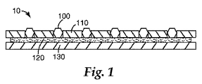
ここで図1を参照すると、本発明のある実施形態の研磨物品の製造における中間体の模式的な断面図が示されている。この実施形態では、実質的に空隙中に提供された研磨粒子100を有する中間体研磨物品10が示されており、空隙は金属箔110内に設けられている。第2構成要素130は、結合層120によって残りの構造に固定されている。結合層は、例えば、感圧接着剤層又はホットメルト接着剤などの接着剤であることができる。
Referring now to FIG. 1, there is shown a schematic cross-sectional view of an intermediate in the manufacture of an abrasive article of an embodiment of the present invention. In this embodiment, an intermediate
図2は、本発明のある実施形態の研磨物品の製造における別の中間体の模式的な断面図である。この実施形態では、実質的に空隙中に提供された研磨粒子200を有する研磨物品前駆体20が表されており、空隙は、金属箔210内に設けられている。第2構成要素230は、残りの構造体に固定されている。この模式的な断面図は、電着した第2構成要素230を表しており、更には図1に示すような態様の、図1に示した結合層を除去する条件で更に加工したものも表している。例えば、熱及び/又は圧力を用いて有機接着剤組成物を燃やし尽くすか又は押し出すことで、図1に示した実施態様の模式的な断面を、図2に示した模式的な断面へ有効に変換することができる。
FIG. 2 is a schematic cross-sectional view of another intermediate in the manufacture of an abrasive article according to an embodiment of the present invention. In this embodiment, the
図3は、本発明のある実施形態の研磨物品の模式的な断面図を示している。この実施形態では、実質的に空隙中に提供された研磨粒子300を有する研磨物品30が表されており、空隙は、金属箔310内に設けられている。第2構成要素330は、残りの構造体に固定されている。合金350は、研磨粒子300と隣接して、並びに金属箔310及び第2構成要素330とも隣接して示されている。いくつかの実施形態では、研磨粒子300は、第2構成要素330と隣接しているか、実質的にそれと接触しており、接触領域370ではそれらの間に合金がほとんど又は全くない。いくつかの実施形態では、合金380は研磨粒子300と第2構成要素330の間に存在する。当然、合金380と接触領域370とを有する研磨物品の組み合わせも入手可能である。
FIG. 3 shows a schematic cross-sectional view of an abrasive article according to an embodiment of the present invention. In this embodiment, an
いくつかの実施形態では、箔構成要素内の空隙は非貫通孔である。かかる実施形態では、第2構成要素は好ましくは、空隙に付随する表面開口部を含有する箔の側面に供給される。 In some embodiments, the voids in the foil component are non-through holes. In such embodiments, the second component is preferably fed to the side of the foil that contains the surface opening associated with the void.
いくつかの実施形態では、研磨物品が基材を包含しており、基材は任意に、箔と第2構成要素との間に形成された合金によって、合金が形成されるときに箔に接合されてよい。かかる実施形態では、基材は、特に基材周辺では、合金の組成に寄与する場合がある。他の実施形態では、更に厚い第2構成要素を基材として役立てることも可能である。更に別の実施形態では、基材は、別々の操作で供給されてもよく、当該技術分野において既知のいかなる手段、例えば、はんだ接着剤、ロウ付け、溶接、及び機械的な締結具の利用によって接着されてもよい。基材は、金属、合金、ポリマー、ポリスチレン、ポリカーボネート、ステンレス鋼、セラミック、又はこれらの組み合わせから選択されてよい。 In some embodiments, the abrasive article includes a substrate, and the substrate is optionally joined to the foil when the alloy is formed by an alloy formed between the foil and the second component. May be. In such embodiments, the substrate may contribute to the alloy composition, particularly around the substrate. In other embodiments, a thicker second component can also serve as the substrate. In yet another embodiment, the substrate may be supplied in a separate operation, by any means known in the art, such as the use of solder adhesive, brazing, welding, and mechanical fasteners. It may be adhered. The substrate may be selected from metals, alloys, polymers, polystyrene, polycarbonate, stainless steel, ceramic, or combinations thereof.
いくつかの実施形態では、研磨物品には、既知の保護コーティングの一つ、例えば、ダイアモンド様のカーボンコーティングが提供されてもよい。かかるコーティングは、あらゆる既知の手段、例えば、物理気相成長法、化学気相成長法、及び電解メッキによって提供することができる。他の実施形態では、箔が研磨物品の露出表面積の大部分を占める場合もあり、これは、物品全体を保護するのに十分な耐食性を有し得る。他の実施形態では、箔は、使用条件下で徐々に侵食されて、新たな研磨粒子を絶えず露出させるように選択されてよい。 In some embodiments, the abrasive article may be provided with one of the known protective coatings, such as a diamond-like carbon coating. Such a coating can be provided by any known means such as physical vapor deposition, chemical vapor deposition, and electroplating. In other embodiments, the foil may occupy a majority of the exposed surface area of the abrasive article, which may have sufficient corrosion resistance to protect the entire article. In other embodiments, the foil may be selected to erode gradually under the conditions of use, constantly exposing new abrasive particles.
記載した記述内容は、工作物表面に平行に適用できる研磨層又は複数層を提供するものと解されてよいが、この層又は複数層は、工作物表面に任意の所望の向きで適用されてもよいと解されるべきである。 The described content may be understood to provide an abrasive layer or layers that can be applied parallel to the workpiece surface, but this layer or layers applied to the workpiece surface in any desired orientation. Should be understood as good.
本発明は、産業用研磨物品、例えば、CMPパッドコンディショナー、構造のこ刃、研削ツール、ドリルなどに有用である。 The present invention is useful for industrial abrasive articles such as CMP pad conditioners, structured saw blades, grinding tools, drills, and the like.
本発明の目的及び利点を、以下の実施例によって更に例示するが、これらの実施例において列挙される特定の材料及びその量並びに他の諸条件及び詳細によって、本発明を不当に制限するものではないと解釈すべきである。 Objects and advantages of this invention are further illustrated by the following examples, which are not intended to unduly limit this invention by the particular materials and amounts thereof listed in these examples, as well as other conditions and details. Should not be interpreted.
(実施例1)
研磨箔は、ジルコニウム箔(0.051mm(0.002インチ)厚であり、直径0.25mm(0.0098インチ)の穴を3.63mm(0.0143インチ)間隔で配置した矩形配列を含む外径96mm(3.78インチ)×内径58.4mm(2.30インチ)の環状領域を有するもの)の127mm×127mm(5インチ四方)のパターン付きマスクから調製した。接着剤テープ(品番7741、ミネソタ州セント・ポール(Saint Paul)の3Mから入手されるもの)をジルコニウム箔パターン付きマスクの第1表面に貼付して、プリフォームを作製した。ダイアモンド粒子(181ミクロン)に100nmの炭化クロムのコーティングを後でコーティングし、次いでそれらを、マスク/テープアセンブリの第2表面に振りかけることによって、個々の研磨粒子を、箔の穴から露出している接着剤に付着させた。過剰の研磨粒子を取り除いた。0.127mm(0.005インチ)のニッケルくさびを次に、前述のプリフォーム(perform)の接着剤の第1表面と隣接して配置して、この複合材料を、0.10MPa(760mmHg)の低真空にしながら、19.6MPa(200kg/cm−2(200kg cm2))の圧力下で1020℃まで加熱した。
Example 1
The polishing foil is a zirconium foil (0.051 mm (0.002 inch) thick and includes a rectangular array of holes having a diameter of 0.25 mm (0.0098 inch) arranged at intervals of 3.63 mm (0.0143 inch). Prepared from a 127 mm × 127 mm (5 inch square) patterned mask with an outer diameter of 96 mm (3.78 inches) × an inner diameter of 58.4 mm (2.30 inches). An adhesive tape (Part No. 7741, available from 3M, Saint Paul, Minn.) Was applied to the first surface of the mask with a zirconium foil pattern to make a preform. Individual abrasive particles are exposed from the foil holes by subsequently coating diamond particles (181 microns) with a 100 nm chromium carbide coating and then sprinkling them onto the second surface of the mask / tape assembly. Adhered to the adhesive. Excess abrasive particles were removed. A 0.127 mm (0.005 inch) nickel wedge was then placed adjacent to the first surface of the preform adhesive described above, and the composite material was 0.10 MPa (760 mmHg). while at low vacuum and heated to 1020 ° C. under a pressure of 19.6MPa (200kg / cm -2 (200kg cm 2)).
(実施例2)
ニッケル箔を、カナダ・トロント(Toronto)のインコ(Inco)製ニッケル(Nickel)123粉末と、ポリビニルブチラール、フタル酸ブチルベンジル可塑剤、及びメチルエチルケトン(MEK)との混合物から形成された溶媒流延ニッケル粉末テープであって、間隙0.33mm(13ミル)を有するナイフコーターでコーティングして乾燥させたものに置き換えたこと以外は、実施例1と同様にして、研磨箔を調製した。
(Example 2)
Nickel foil is a solvent cast nickel formed from a mixture of Nickel 123 powder from Inco, Toronto, Canada, polyvinyl butyral, butyl benzyl phthalate plasticizer, and methyl ethyl ketone (MEK). A polishing foil was prepared in the same manner as in Example 1 except that it was replaced with a powder tape that was coated with a knife coater having a gap of 0.33 mm (13 mils) and dried.
(実施例3)
粉末テープを、4重量部のNi/Cr対1重量%部のBNi7の割合のニッケル/クロム粉末及びBNi7ロウ付け粉末と、ポリビニルブチラール及びMEKとを併せて形成した溶剤流延粉末テープと置き換えたこと以外は、実施例2と同様にして、研磨箔を調製して試験した。ダイアモンド粒子(181ミクロン)は本実施例でも使用した。冷却してから、複合材料を切り取って鋼製キャリアテープに接着し、11.2rpmで振動させながら85rpmで作動するストラスバー(Strasbaugh)に実装したIC 1000(アリゾナ州フェニックス(Phoenix)のローム・アンド・ハース・エレクトリニック・マテリアルズ(Rohm and Haas Electronic Materials)製)パッドを、直径108mm(4.25インチ)の銅スラグ上でコンディショナー力31.1N(7ポンド)及びダウンフォース182.4N(41ポンド)で調整することによって試験した。3つの要素全てを同時に回転させた。試験は、毎分75mLで供給されるスラリー(アリゾナ州テンペ(Tempe)のDAナノマテリアルズ(DA Nanomaterials)製のDAナノ・コペレディ(DA Nano CoppeReady)300)の存在下で行った。パッド厚さ及び金属屑除去速度を測定した。最初の一時間は15分間隔で試験し、そしてその後は1時間毎に試験して、標準的な基材に対するパッドコンディショナーの切削速度を測定した。切削速度が初期値の20%未満まで低下したときに、表Iに報告するように、コンディショナーはその寿命に達したとみなした。
(Example 3)
The powder tape was replaced with a solvent cast powder tape formed by combining 4 parts by weight of Ni / Cr to 1% by weight of BNi7 nickel / chrome powder and BNi7 brazing powder with polyvinyl butyral and MEK. Except for this, a polishing foil was prepared and tested as in Example 2. Diamond particles (181 microns) were also used in this example. After cooling, the composite material was cut and glued to a steel carrier tape and mounted on a Strasbaugh operating at 85 rpm while vibrating at 11.2 rpm, Rohm & from Phoenix, Arizona A pad of Rohm and Haas Electronic Materials padded on a 108 mm (4.25 inch) diameter copper slag with a conditioner force of 31.1 N (7 lbs) and a downforce of 182.4 N (41 Lb). All three elements were rotated simultaneously. The test was conducted in the presence of a slurry (DA

(実施例4)
ニッケル箔を、3重量部のZr対1重量部のニッケル(Nickel)123の割合のジルコニウム粉末及びニッケル123粉末と、ポリビニル及びMEKとを併せて作製した溶剤流延粉末テープに置き換えたこと以外は、実施例1と同様にして研磨箔を調製した。
Example 4
Except for replacing the nickel foil with a solvent cast powder tape made by combining 3 parts by weight of Zr to 1 part by weight of nickel (Nickel) 123 zirconium powder and nickel 123 powder, and polyvinyl and MEK. A polishing foil was prepared in the same manner as in Example 1.
(実施例5)
ニッケル箔を、BNi7ロウ付け粉末と、ポリビニルブチラールと、MEKとの混合物から形成された溶剤流延粉末テープであって、間隙0.33mm(13ミル)のナイフコーターを用いてコーティングして乾燥させたものに置き換えたこと以外は、実施例1と同様にして多層研磨材を調製した。その後、実施例1と同様にして、ジルコニウム箔、ダイアモンド、接着剤テープの層(3層)と溶剤流延粉末テープの層(4層)とを交互に組み立てて加熱した。
(Example 5)
A nickel foil is a solvent cast powder tape formed from a mixture of BNi7 brazing powder, polyvinyl butyral, and MEK, coated and dried using a knife coater with a gap of 0.33 mm (13 mils). A multilayer abrasive was prepared in the same manner as in Example 1 except that it was replaced with the above. Thereafter, in the same manner as in Example 1, layers (three layers) of zirconium foil, diamond and adhesive tape and layers (four layers) of solvent cast powder tape were alternately assembled and heated.
(実施例6)
ニッケル箔を、BNi7ロウ付け粉末と、ポリビニルブチラールと、MEKとの混合物から形成した溶剤流延ロウ付け合金粉末テープであって、間隙0.33mm(13ミル)のナイフコーターを用いてコーティングして乾燥させたものに置き換えたこと以外は、実施例1と同様にして、研磨箔を調製した。
(Example 6)
A nickel foil is a solvent cast brazing alloy powder tape formed from a mixture of BNi7 brazing powder, polyvinyl butyral and MEK, coated using a knife coater with a gap of 0.33 mm (13 mils). A polishing foil was prepared in the same manner as in Example 1 except that it was replaced with a dried one.
本発明の様々な修正及び変更は、本発明の範囲及び原理から逸脱することなく当業者には明白であり、また、本発明は、本明細書に記載した例示的な実施形態に不当に制限されるものではないと理解すべきである。すべての刊行物及び特許は、個々の刊行物又は特許それぞれがあたかも具体的に及び個別に示されて参照として組み込まれているのとの同程度まで、本明細書に参照として組み込まれる。 Various modifications and alterations of this invention will be apparent to those skilled in the art without departing from the scope and principles of this invention, and the present invention is unduly limited to the exemplary embodiments described herein. It should be understood that it is not done. All publications and patents are incorporated herein by reference to the same extent as if each individual publication or patent was specifically and individually shown and incorporated by reference.
Claims (5)
(a)第1表面及び第2表面、並びにそれらの間の空隙を有し、チタンまたはジルコニウムから成る、金属箔と、
(b)実質的に前記箔の前記第1及び第2表面との間の前記空隙中の複数の研磨粒子と、
(c)前記研磨粒子と前記箔との間に少なくとも部分的に存する合金と、を含み、
前記合金が、前記研磨粒子付近で第2構成要素と前記金属箔の一部を含み、前記金属箔が、研磨物品の接触面の大部分を形成する、研磨物品。 An abrasive article,
(A) first and second surfaces, and have a gap between them, made of titanium or zirconium, a metal foil,
(B) a plurality of abrasive particles substantially in the gap between the first and second surfaces of the foil;
(C) an alloy present at least partially between the abrasive particles and the foil,
An abrasive article, wherein the alloy includes a second component and a portion of the metal foil near the abrasive particles, the metal foil forming a majority of a contact surface of the abrasive article.
Applications Claiming Priority (3)
| Application Number | Priority Date | Filing Date | Title |
|---|---|---|---|
| US82404806P | 2006-08-30 | 2006-08-30 | |
| US60/824,048 | 2006-08-30 | ||
| PCT/US2007/075791 WO2008027714A1 (en) | 2006-08-30 | 2007-08-13 | Extended life abrasive article and method |
Publications (3)
| Publication Number | Publication Date |
|---|---|
| JP2010502458A JP2010502458A (en) | 2010-01-28 |
| JP2010502458A5 JP2010502458A5 (en) | 2010-10-14 |
| JP5285609B2 true JP5285609B2 (en) | 2013-09-11 |
Family
ID=39136260
Family Applications (1)
| Application Number | Title | Priority Date | Filing Date |
|---|---|---|---|
| JP2009526795A Expired - Fee Related JP5285609B2 (en) | 2006-08-30 | 2007-08-13 | Abrasive article and method with extended life |
Country Status (7)
| Country | Link |
|---|---|
| US (1) | US8377158B2 (en) |
| EP (1) | EP2076360A4 (en) |
| JP (1) | JP5285609B2 (en) |
| KR (1) | KR101483314B1 (en) |
| CN (1) | CN101511542B (en) |
| TW (1) | TWI522447B (en) |
| WO (1) | WO2008027714A1 (en) |
Families Citing this family (52)
| Publication number | Priority date | Publication date | Assignee | Title |
|---|---|---|---|---|
| US9199357B2 (en) * | 1997-04-04 | 2015-12-01 | Chien-Min Sung | Brazed diamond tools and methods for making the same |
| US9409280B2 (en) | 1997-04-04 | 2016-08-09 | Chien-Min Sung | Brazed diamond tools and methods for making the same |
| US9463552B2 (en) | 1997-04-04 | 2016-10-11 | Chien-Min Sung | Superbrasvie tools containing uniformly leveled superabrasive particles and associated methods |
| US9221154B2 (en) | 1997-04-04 | 2015-12-29 | Chien-Min Sung | Diamond tools and methods for making the same |
| US9868100B2 (en) | 1997-04-04 | 2018-01-16 | Chien-Min Sung | Brazed diamond tools and methods for making the same |
| US9238207B2 (en) | 1997-04-04 | 2016-01-19 | Chien-Min Sung | Brazed diamond tools and methods for making the same |
| US8678878B2 (en) | 2009-09-29 | 2014-03-25 | Chien-Min Sung | System for evaluating and/or improving performance of a CMP pad dresser |
| US9138862B2 (en) | 2011-05-23 | 2015-09-22 | Chien-Min Sung | CMP pad dresser having leveled tips and associated methods |
| US8393934B2 (en) | 2006-11-16 | 2013-03-12 | Chien-Min Sung | CMP pad dressers with hybridized abrasive surface and related methods |
| US9724802B2 (en) | 2005-05-16 | 2017-08-08 | Chien-Min Sung | CMP pad dressers having leveled tips and associated methods |
| DE102008021636B3 (en) * | 2008-04-30 | 2009-11-19 | Esk Ceramics Gmbh & Co. Kg | Method for fixing a connecting element on a workpiece and component of a workpiece with a connecting element fixed thereon |
| JP2009302136A (en) * | 2008-06-10 | 2009-12-24 | Panasonic Corp | Semiconductor integrated circuit |
| US9221148B2 (en) | 2009-04-30 | 2015-12-29 | Rdc Holdings, Llc | Method and apparatus for processing sliders for disk drives, and to various processing media for the same |
| US8801497B2 (en) | 2009-04-30 | 2014-08-12 | Rdc Holdings, Llc | Array of abrasive members with resilient support |
| US20110104989A1 (en) * | 2009-04-30 | 2011-05-05 | First Principles LLC | Dressing bar for embedding abrasive particles into substrates |
| US20100330890A1 (en) | 2009-06-30 | 2010-12-30 | Zine-Eddine Boutaghou | Polishing pad with array of fluidized gimballed abrasive members |
| JP5537660B2 (en) | 2009-08-14 | 2014-07-02 | サンーゴバン アブレイシブズ,インコーポレイティド | Abrasive article comprising abrasive particles bonded to an elongated object and method of forming the abrasive article |
| JP5542938B2 (en) | 2009-08-14 | 2014-07-09 | サンーゴバン アブレイシブズ,インコーポレイティド | Abrasive article comprising abrasive particles bonded to an elongated object |
| US20110073094A1 (en) * | 2009-09-28 | 2011-03-31 | 3M Innovative Properties Company | Abrasive article with solid core and methods of making the same |
| DE102010038324B4 (en) * | 2010-07-23 | 2012-03-22 | Hilti Aktiengesellschaft | Device for positioning cutting particles |
| TWI544064B (en) | 2010-09-03 | 2016-08-01 | 聖高拜磨料有限公司 | Bonded abrasive article and method of forming |
| TW201223699A (en) * | 2010-09-03 | 2012-06-16 | Saint Gobain Abrasives Inc | Bonded abrasive articles, method of forming such articles, and grinding performance of such articles |
| TW201507812A (en) | 2010-12-30 | 2015-03-01 | Saint Gobain Abrasives Inc | Abrasive article and method of forming |
| CN102601747B (en) * | 2011-01-20 | 2015-12-09 | 中芯国际集成电路制造(上海)有限公司 | A kind of grinding pad and preparation method thereof, using method |
| CN103329253B (en) | 2011-05-23 | 2016-03-30 | 宋健民 | There is the CMP pad dresser at planarization tip |
| KR101618040B1 (en) | 2011-09-16 | 2016-05-04 | 생-고뱅 어브레이시브즈, 인코포레이티드 | Abrasive article and method of forming |
| EP2760638A4 (en) | 2011-09-29 | 2015-05-27 | Saint Gobain Abrasives Inc | Abrasive articles including abrasive particles bonded to an elongated substrate body having a barrier layer, and methods of forming thereof |
| US9644283B2 (en) * | 2011-09-30 | 2017-05-09 | Apple Inc. | Laser texturizing and anodization surface treatment |
| CN102601746B (en) * | 2012-02-29 | 2015-04-08 | 河南富耐克超硬材料股份有限公司 | Abrasive disc for flexible abrasive tool and method for manufacturing abrasive disc |
| JP5972032B2 (en) * | 2012-05-01 | 2016-08-17 | 新技術開発株式会社 | Polishing tool for high-efficiency precision machining and its manufacturing method |
| TWI655057B (en) * | 2012-05-04 | 2019-04-01 | 美商恩特葛瑞斯股份有限公司 | Chemical mechanical polishing pad dresser |
| TW201404527A (en) | 2012-06-29 | 2014-02-01 | Saint Gobain Abrasives Inc | Abrasive article and method of forming |
| TW201402274A (en) | 2012-06-29 | 2014-01-16 | Saint Gobain Abrasives Inc | Abrasive article and method of forming |
| TWI477343B (en) | 2012-06-29 | 2015-03-21 | Saint Gobain Abrasives Inc | Abrasive article and method of forming |
| TWI474889B (en) | 2012-06-29 | 2015-03-01 | Saint Gobain Abrasives Inc | Abrasive article and method of forming |
| EP2906392A4 (en) * | 2012-10-15 | 2016-07-13 | Saint Gobain Abrasives Inc | Abrasive particles having particular shapes and methods of forming such particles |
| WO2014106159A1 (en) | 2012-12-31 | 2014-07-03 | Saint-Gobain Abrasives, Inc. | Bonded abrasive article and method of grinding |
| EP2938460B1 (en) | 2012-12-31 | 2018-08-15 | Saint-Gobain Abrasives, Inc. | Method of grinding |
| CN104994996B (en) | 2012-12-31 | 2017-12-05 | 圣戈班磨料磨具有限公司 | Bonded abrasive articles and method for grinding |
| US9833877B2 (en) | 2013-03-31 | 2017-12-05 | Saint-Gobain Abrasives, Inc. | Bonded abrasive article and method of grinding |
| TW201441355A (en) | 2013-04-19 | 2014-11-01 | Saint Gobain Abrasives Inc | Abrasive article and method of forming |
| EP2835220B1 (en) * | 2013-08-07 | 2019-09-11 | Reishauer AG | Trimming tool, and method for manufacturing the same |
| EP2859997B1 (en) | 2013-10-08 | 2015-09-30 | Valentini, Guido | Method for manufacturing a polishing pad and polishing pad |
| US10786875B2 (en) * | 2014-07-02 | 2020-09-29 | Raytheon Technologies Corporation | Abrasive preforms and manufacture and use methods |
| WO2016106020A1 (en) * | 2014-12-22 | 2016-06-30 | 3M Innovative Properties Company | Abrasive articles with removable abrasive member and methods of separating and replacing thereof |
| TWI621505B (en) | 2015-06-29 | 2018-04-21 | 聖高拜磨料有限公司 | Abrasive article and method of forming |
| CN107520770B (en) * | 2017-05-04 | 2019-03-08 | 漳州职业技术学院 | A kind of wear-resisting skive preparation method of abrasive grain crystal orientation distribution |
| CN107081688A (en) * | 2017-05-27 | 2017-08-22 | 江苏省江南新型复合研磨材料及制品工程技术研究中心有限公司 | The multiple grinding piece and its manufacture method of a kind of high-strength high-performance |
| KR102013386B1 (en) * | 2018-01-29 | 2019-08-22 | 새솔다이아몬드공업 주식회사 | Manufacturing method of pad conditioner by reverse plating and pad conditioner thereof |
| JP7012729B2 (en) * | 2018-02-08 | 2022-01-28 | 住友電気工業株式会社 | Super-abrasive grain and super-abrasive wheel |
| US11331767B2 (en) | 2019-02-01 | 2022-05-17 | Micron Technology, Inc. | Pads for chemical mechanical planarization tools, chemical mechanical planarization tools, and related methods |
| KR102227790B1 (en) * | 2019-11-11 | 2021-03-15 | 동신다이아몬드공업 주식회사 | Diamond Tool and Manufacturing Method |
Family Cites Families (31)
| Publication number | Priority date | Publication date | Assignee | Title |
|---|---|---|---|---|
| US3675311A (en) * | 1970-07-02 | 1972-07-11 | Northrop Corp | Thin-film diffusion brazing of nickel and nickel base alloys |
| US4029479A (en) * | 1973-01-29 | 1977-06-14 | Rohr Industries, Inc. | Plated foil for liquid interface bonding of titanium |
| US4706872A (en) * | 1986-10-16 | 1987-11-17 | Rohr Industries, Inc. | Method of bonding columbium to nickel and nickel based alloys using low bonding pressures and temperatures |
| JPH0197570A (en) | 1987-10-06 | 1989-04-17 | Noritake Dia Kk | Diamond grinding material for metal bond grinding stone |
| JPH01246516A (en) * | 1988-03-29 | 1989-10-02 | Sony Corp | Focus position detector |
| US5049165B1 (en) * | 1989-01-30 | 1995-09-26 | Ultimate Abrasive Syst Inc | Composite material |
| JP3026988B2 (en) * | 1990-02-05 | 2000-03-27 | 東京磁気印刷株式会社 | Polishing tool |
| JPH04129660A (en) * | 1990-09-19 | 1992-04-30 | Hitachi Ltd | Magnetic disk and surface processing method of substrate thereof |
| CN2104731U (en) * | 1991-07-24 | 1992-05-20 | 张希浩 | Electroplating diamond grinding tool |
| US5234152A (en) * | 1992-01-07 | 1993-08-10 | Regents Of The University Of California | Transient liquid phase ceramic bonding |
| US6654061B2 (en) * | 1995-06-14 | 2003-11-25 | Canon Kabushiki Kaisha | Automatic focus adjusting apparatus and method utilized by an image sensing apparatus |
| US7124753B2 (en) | 1997-04-04 | 2006-10-24 | Chien-Min Sung | Brazed diamond tools and methods for making the same |
| TW394723B (en) * | 1997-04-04 | 2000-06-21 | Sung Chien Min | Abrasive tools with patterned grit distribution and method of manufacture |
| US6884155B2 (en) * | 1999-11-22 | 2005-04-26 | Kinik | Diamond grid CMP pad dresser |
| US20040112359A1 (en) * | 1997-04-04 | 2004-06-17 | Chien-Min Sung | Brazed diamond tools and methods for making the same |
| US6537140B1 (en) * | 1997-05-14 | 2003-03-25 | Saint-Gobain Abrasives Technology Company | Patterned abrasive tools |
| US6123612A (en) * | 1998-04-15 | 2000-09-26 | 3M Innovative Properties Company | Corrosion resistant abrasive article and method of making |
| JP2000106353A (en) * | 1998-07-31 | 2000-04-11 | Nippon Steel Corp | Dresser for polishing cloth for semiconductor substrate |
| TW467809B (en) * | 1999-12-17 | 2001-12-11 | Ultimate Abrasive Systems Llc | Abrasive surface and article and methods for making them |
| US20020012063A1 (en) * | 2000-03-10 | 2002-01-31 | Olympus Optical Co., Ltd. | Apparatus for automatically detecting focus and camera equipped with automatic focus detecting apparatus |
| JP2002209912A (en) * | 2001-01-22 | 2002-07-30 | Masayuki Nakagawa | Structure of disk-shaped superfine abrasive electrodeposition grinding wheel dedicated to model trimmer for dental technique |
| FR2820666B1 (en) * | 2001-02-14 | 2003-04-11 | Arjo Wiggins Sa | SELF-GRIPPING SUPPORT FOR AN APPLIED ABRASIVE PRODUCT AND METHOD FOR MANUFACTURING SAID ABRASIVE PRODUCT INCORPORATING THE SAME |
| US6669745B2 (en) * | 2001-02-21 | 2003-12-30 | 3M Innovative Properties Company | Abrasive article with optimally oriented abrasive particles and method of making the same |
| JP2003051980A (en) * | 2001-08-08 | 2003-02-21 | Matsushita Electric Ind Co Ltd | Automatic focus device, imaging device and camera system |
| JP3795786B2 (en) * | 2001-10-09 | 2006-07-12 | 敬久 山崎 | Brazed diamond and diamond brazing method |
| JP3975395B2 (en) * | 2002-02-26 | 2007-09-12 | フジノン株式会社 | Camera system |
| JP4045483B2 (en) * | 2002-03-13 | 2008-02-13 | フジノン株式会社 | Focus status detection device |
| JP4647885B2 (en) * | 2003-02-17 | 2011-03-09 | 株式会社ニコン | camera |
| JP4463084B2 (en) * | 2003-11-27 | 2010-05-12 | 株式会社オクテック | Dressing tools |
| JP2005219152A (en) * | 2004-02-04 | 2005-08-18 | Ebara Corp | Dresser and method of manufacturing the same |
| JP4506634B2 (en) | 2005-10-03 | 2010-07-21 | トヨタ紡織株式会社 | Filter and cleaner |
-
2007
- 2007-08-13 WO PCT/US2007/075791 patent/WO2008027714A1/en active Application Filing
- 2007-08-13 JP JP2009526795A patent/JP5285609B2/en not_active Expired - Fee Related
- 2007-08-13 EP EP07814031A patent/EP2076360A4/en not_active Withdrawn
- 2007-08-13 CN CN2007800324263A patent/CN101511542B/en not_active Expired - Fee Related
- 2007-08-13 KR KR20097004215A patent/KR101483314B1/en not_active IP Right Cessation
- 2007-08-13 US US11/837,774 patent/US8377158B2/en not_active Expired - Fee Related
- 2007-08-23 TW TW096131276A patent/TWI522447B/en not_active IP Right Cessation
Also Published As
| Publication number | Publication date |
|---|---|
| CN101511542B (en) | 2011-05-25 |
| US8377158B2 (en) | 2013-02-19 |
| TW200819523A (en) | 2008-05-01 |
| US20080053000A1 (en) | 2008-03-06 |
| EP2076360A4 (en) | 2012-12-19 |
| JP2010502458A (en) | 2010-01-28 |
| EP2076360A1 (en) | 2009-07-08 |
| CN101511542A (en) | 2009-08-19 |
| KR20090049594A (en) | 2009-05-18 |
| WO2008027714A1 (en) | 2008-03-06 |
| KR101483314B1 (en) | 2015-01-15 |
| TWI522447B (en) | 2016-02-21 |
Similar Documents
| Publication | Publication Date | Title |
|---|---|---|
| JP5285609B2 (en) | Abrasive article and method with extended life | |
| JP5647689B2 (en) | Abrasive article having a solid core and method for producing the article | |
| CA2287199C (en) | Patterned abrasive tools | |
| US7124753B2 (en) | Brazed diamond tools and methods for making the same | |
| US8104464B2 (en) | Brazed diamond tools and methods for making the same | |
| US9868100B2 (en) | Brazed diamond tools and methods for making the same | |
| EP2083967A1 (en) | Conditioning tools and techniques for chemical mechanical planarization | |
| JP2007083389A (en) | Cmp diamond conditioning disk | |
| KR20050040934A (en) | Molten braze-coated superabrasive particles and associated methods | |
| JP7191153B2 (en) | Ceramic substrate with reaction-bonded silicon carbide containing diamond particles | |
| EP1927434A1 (en) | CMP conditioner | |
| US10183378B2 (en) | Grinding tool | |
| JP2002127017A (en) | Dresser for polishing cloth and its manufacture | |
| KR100615707B1 (en) | Manufacturing method for grinding and cutting tool using metal brazing | |
| KR100688862B1 (en) | Diamond tool manufacturing method and diamond tool made of the method | |
| JPH10230465A (en) | Porous diamond wheel | |
| JP2006026870A (en) | Super-abrasive grain sintered body throw-away tip | |
| IES85564Y1 (en) | An abrasive material, wheel and tool for grinding semiconductor substrates, and method of manufacture of same | |
| TW200843902A (en) | A flexible lapping tool and its manufacturing method | |
| JP2010058219A (en) | Truing tool |
Legal Events
| Date | Code | Title | Description |
|---|---|---|---|
| A521 | Written amendment |
Free format text: JAPANESE INTERMEDIATE CODE: A523 Effective date: 20100730 |
|
| A621 | Written request for application examination |
Free format text: JAPANESE INTERMEDIATE CODE: A621 Effective date: 20100730 |
|
| A131 | Notification of reasons for refusal |
Free format text: JAPANESE INTERMEDIATE CODE: A131 Effective date: 20120619 |
|
| A977 | Report on retrieval |
Free format text: JAPANESE INTERMEDIATE CODE: A971007 Effective date: 20120621 |
|
| A601 | Written request for extension of time |
Free format text: JAPANESE INTERMEDIATE CODE: A601 Effective date: 20120919 |
|
| A602 | Written permission of extension of time |
Free format text: JAPANESE INTERMEDIATE CODE: A602 Effective date: 20120926 |
|
| A521 | Written amendment |
Free format text: JAPANESE INTERMEDIATE CODE: A523 Effective date: 20121019 |
|
| RD03 | Notification of appointment of power of attorney |
Free format text: JAPANESE INTERMEDIATE CODE: A7423 Effective date: 20121214 |
|
| RD04 | Notification of resignation of power of attorney |
Free format text: JAPANESE INTERMEDIATE CODE: A7424 Effective date: 20121219 |
|
| A01 | Written decision to grant a patent or to grant a registration (utility model) |
Free format text: JAPANESE INTERMEDIATE CODE: A01 Effective date: 20130507 |
|
| A61 | First payment of annual fees (during grant procedure) |
Free format text: JAPANESE INTERMEDIATE CODE: A61 Effective date: 20130531 |
|
| R250 | Receipt of annual fees |
Free format text: JAPANESE INTERMEDIATE CODE: R250 |
|
| LAPS | Cancellation because of no payment of annual fees |