US9856702B2 - Cutting element for a downhole tool - Google Patents
Cutting element for a downhole tool Download PDFInfo
- Publication number
- US9856702B2 US9856702B2 US14/487,942 US201414487942A US9856702B2 US 9856702 B2 US9856702 B2 US 9856702B2 US 201414487942 A US201414487942 A US 201414487942A US 9856702 B2 US9856702 B2 US 9856702B2
- Authority
- US
- United States
- Prior art keywords
- carbide
- composite material
- pellets
- cutting element
- diamond particles
- Prior art date
- Legal status (The legal status is an assumption and is not a legal conclusion. Google has not performed a legal analysis and makes no representation as to the accuracy of the status listed.)
- Active, expires
Links
- 238000005520 cutting process Methods 0.000 title claims abstract description 133
- 239000000463 material Substances 0.000 claims abstract description 131
- 239000002131 composite material Substances 0.000 claims abstract description 91
- 239000002245 particle Substances 0.000 claims abstract description 85
- 239000010432 diamond Substances 0.000 claims abstract description 62
- 229910003460 diamond Inorganic materials 0.000 claims abstract description 62
- 239000011230 binding agent Substances 0.000 claims abstract description 58
- 239000008188 pellet Substances 0.000 claims abstract description 45
- 239000000758 substrate Substances 0.000 claims description 33
- 238000000034 method Methods 0.000 claims description 21
- 239000011248 coating agent Substances 0.000 claims description 14
- 238000000576 coating method Methods 0.000 claims description 14
- 238000005245 sintering Methods 0.000 claims description 14
- 229910052751 metal Inorganic materials 0.000 claims description 11
- 239000002184 metal Substances 0.000 claims description 11
- 230000008569 process Effects 0.000 claims description 11
- XEEYBQQBJWHFJM-UHFFFAOYSA-N Iron Chemical compound [Fe] XEEYBQQBJWHFJM-UHFFFAOYSA-N 0.000 claims description 10
- PXHVJJICTQNCMI-UHFFFAOYSA-N Nickel Chemical compound [Ni] PXHVJJICTQNCMI-UHFFFAOYSA-N 0.000 claims description 10
- MTPVUVINMAGMJL-UHFFFAOYSA-N trimethyl(1,1,2,2,2-pentafluoroethyl)silane Chemical compound C[Si](C)(C)C(F)(F)C(F)(F)F MTPVUVINMAGMJL-UHFFFAOYSA-N 0.000 claims description 9
- 229910003468 tantalcarbide Inorganic materials 0.000 claims description 8
- GUTLYIVDDKVIGB-UHFFFAOYSA-N cobalt atom Chemical compound [Co] GUTLYIVDDKVIGB-UHFFFAOYSA-N 0.000 claims description 6
- UNASZPQZIFZUSI-UHFFFAOYSA-N methylidyneniobium Chemical compound [Nb]#C UNASZPQZIFZUSI-UHFFFAOYSA-N 0.000 claims description 6
- NFFIWVVINABMKP-UHFFFAOYSA-N methylidynetantalum Chemical compound [Ta]#C NFFIWVVINABMKP-UHFFFAOYSA-N 0.000 claims description 6
- UONOETXJSWQNOL-UHFFFAOYSA-N tungsten carbide Chemical compound [W+]#[C-] UONOETXJSWQNOL-UHFFFAOYSA-N 0.000 claims description 6
- 229910017052 cobalt Inorganic materials 0.000 claims description 5
- 239000010941 cobalt Substances 0.000 claims description 5
- 229910052759 nickel Inorganic materials 0.000 claims description 5
- 229910052742 iron Inorganic materials 0.000 claims description 4
- HBMJWWWQQXIZIP-UHFFFAOYSA-N silicon carbide Chemical compound [Si+]#[C-] HBMJWWWQQXIZIP-UHFFFAOYSA-N 0.000 claims description 4
- 229910010271 silicon carbide Inorganic materials 0.000 claims description 4
- RTAQQCXQSZGOHL-UHFFFAOYSA-N Titanium Chemical compound [Ti] RTAQQCXQSZGOHL-UHFFFAOYSA-N 0.000 claims description 3
- NRTOMJZYCJJWKI-UHFFFAOYSA-N Titanium nitride Chemical compound [Ti]#N NRTOMJZYCJJWKI-UHFFFAOYSA-N 0.000 claims description 3
- UQZIWOQVLUASCR-UHFFFAOYSA-N alumane;titanium Chemical compound [AlH3].[Ti] UQZIWOQVLUASCR-UHFFFAOYSA-N 0.000 claims description 3
- 238000005219 brazing Methods 0.000 claims description 3
- TWNQGVIAIRXVLR-UHFFFAOYSA-N oxo(oxoalumanyloxy)alumane Chemical compound O=[Al]O[Al]=O TWNQGVIAIRXVLR-UHFFFAOYSA-N 0.000 claims description 3
- 239000010936 titanium Substances 0.000 claims description 3
- 229910052719 titanium Inorganic materials 0.000 claims description 3
- SJKRCWUQJZIWQB-UHFFFAOYSA-N azane;chromium Chemical compound N.[Cr] SJKRCWUQJZIWQB-UHFFFAOYSA-N 0.000 claims 2
- 238000009826 distribution Methods 0.000 description 11
- 230000015572 biosynthetic process Effects 0.000 description 9
- 238000004519 manufacturing process Methods 0.000 description 8
- 238000005553 drilling Methods 0.000 description 7
- 238000003801 milling Methods 0.000 description 6
- 229910052582 BN Inorganic materials 0.000 description 5
- PZNSFCLAULLKQX-UHFFFAOYSA-N Boron nitride Chemical compound N#B PZNSFCLAULLKQX-UHFFFAOYSA-N 0.000 description 5
- 230000006870 function Effects 0.000 description 5
- 239000000843 powder Substances 0.000 description 5
- 239000011435 rock Substances 0.000 description 5
- 229910000831 Steel Inorganic materials 0.000 description 4
- 239000010959 steel Substances 0.000 description 4
- 239000007789 gas Substances 0.000 description 3
- 230000004048 modification Effects 0.000 description 3
- 238000012986 modification Methods 0.000 description 3
- 239000003921 oil Substances 0.000 description 3
- XLYOFNOQVPJJNP-UHFFFAOYSA-N water Substances O XLYOFNOQVPJJNP-UHFFFAOYSA-N 0.000 description 3
- 238000010276 construction Methods 0.000 description 2
- 150000001247 metal acetylides Chemical class 0.000 description 2
- 150000002739 metals Chemical class 0.000 description 2
- VNWKTOKETHGBQD-UHFFFAOYSA-N methane Chemical compound C VNWKTOKETHGBQD-UHFFFAOYSA-N 0.000 description 2
- 239000011812 mixed powder Substances 0.000 description 2
- 239000004215 Carbon black (E152) Substances 0.000 description 1
- 229910010037 TiAlN Inorganic materials 0.000 description 1
- 238000007792 addition Methods 0.000 description 1
- 239000000956 alloy Substances 0.000 description 1
- 229910045601 alloy Inorganic materials 0.000 description 1
- 230000004075 alteration Effects 0.000 description 1
- PNEYBMLMFCGWSK-UHFFFAOYSA-N aluminium oxide Inorganic materials [O-2].[O-2].[O-2].[Al+3].[Al+3] PNEYBMLMFCGWSK-UHFFFAOYSA-N 0.000 description 1
- 238000000429 assembly Methods 0.000 description 1
- 230000000712 assembly Effects 0.000 description 1
- CXOWYMLTGOFURZ-UHFFFAOYSA-N azanylidynechromium Chemical compound [Cr]#N CXOWYMLTGOFURZ-UHFFFAOYSA-N 0.000 description 1
- 230000008901 benefit Effects 0.000 description 1
- 239000004568 cement Substances 0.000 description 1
- 238000005229 chemical vapour deposition Methods 0.000 description 1
- 229910052593 corundum Inorganic materials 0.000 description 1
- 239000010779 crude oil Substances 0.000 description 1
- 230000007547 defect Effects 0.000 description 1
- 230000037430 deletion Effects 0.000 description 1
- 238000012217 deletion Methods 0.000 description 1
- 238000000605 extraction Methods 0.000 description 1
- 229930195733 hydrocarbon Natural products 0.000 description 1
- 150000002430 hydrocarbons Chemical class 0.000 description 1
- 238000007733 ion plating Methods 0.000 description 1
- 238000005259 measurement Methods 0.000 description 1
- 238000005065 mining Methods 0.000 description 1
- 239000003345 natural gas Substances 0.000 description 1
- 238000005240 physical vapour deposition Methods 0.000 description 1
- 238000006467 substitution reaction Methods 0.000 description 1
- 238000007751 thermal spraying Methods 0.000 description 1
- 238000003466 welding Methods 0.000 description 1
- 229910001845 yogo sapphire Inorganic materials 0.000 description 1
Images


Classifications
-
- E—FIXED CONSTRUCTIONS
- E21—EARTH DRILLING; MINING
- E21B—EARTH DRILLING, e.g. DEEP DRILLING; OBTAINING OIL, GAS, WATER, SOLUBLE OR MELTABLE MATERIALS OR A SLURRY OF MINERALS FROM WELLS
- E21B10/00—Drill bits
- E21B10/46—Drill bits characterised by wear resisting parts, e.g. diamond inserts
- E21B10/56—Button-type inserts
- E21B10/567—Button-type inserts with preformed cutting elements mounted on a distinct support, e.g. polycrystalline inserts
-
- B—PERFORMING OPERATIONS; TRANSPORTING
- B24—GRINDING; POLISHING
- B24D—TOOLS FOR GRINDING, BUFFING OR SHARPENING
- B24D3/00—Physical features of abrasive bodies, or sheets, e.g. abrasive surfaces of special nature; Abrasive bodies or sheets characterised by their constituents
- B24D3/02—Physical features of abrasive bodies, or sheets, e.g. abrasive surfaces of special nature; Abrasive bodies or sheets characterised by their constituents the constituent being used as bonding agent
- B24D3/04—Physical features of abrasive bodies, or sheets, e.g. abrasive surfaces of special nature; Abrasive bodies or sheets characterised by their constituents the constituent being used as bonding agent and being essentially inorganic
- B24D3/06—Physical features of abrasive bodies, or sheets, e.g. abrasive surfaces of special nature; Abrasive bodies or sheets characterised by their constituents the constituent being used as bonding agent and being essentially inorganic metallic or mixture of metals with ceramic materials, e.g. hard metals, "cermets", cements
-
- C—CHEMISTRY; METALLURGY
- C04—CEMENTS; CONCRETE; ARTIFICIAL STONE; CERAMICS; REFRACTORIES
- C04B—LIME, MAGNESIA; SLAG; CEMENTS; COMPOSITIONS THEREOF, e.g. MORTARS, CONCRETE OR LIKE BUILDING MATERIALS; ARTIFICIAL STONE; CERAMICS; REFRACTORIES; TREATMENT OF NATURAL STONE
- C04B35/00—Shaped ceramic products characterised by their composition; Ceramics compositions; Processing powders of inorganic compounds preparatory to the manufacturing of ceramic products
- C04B35/515—Shaped ceramic products characterised by their composition; Ceramics compositions; Processing powders of inorganic compounds preparatory to the manufacturing of ceramic products based on non-oxide ceramics
- C04B35/56—Shaped ceramic products characterised by their composition; Ceramics compositions; Processing powders of inorganic compounds preparatory to the manufacturing of ceramic products based on non-oxide ceramics based on carbides or oxycarbides
- C04B35/5607—Shaped ceramic products characterised by their composition; Ceramics compositions; Processing powders of inorganic compounds preparatory to the manufacturing of ceramic products based on non-oxide ceramics based on carbides or oxycarbides based on refractory metal carbides
- C04B35/5611—Shaped ceramic products characterised by their composition; Ceramics compositions; Processing powders of inorganic compounds preparatory to the manufacturing of ceramic products based on non-oxide ceramics based on carbides or oxycarbides based on refractory metal carbides based on titanium carbides
-
- C—CHEMISTRY; METALLURGY
- C04—CEMENTS; CONCRETE; ARTIFICIAL STONE; CERAMICS; REFRACTORIES
- C04B—LIME, MAGNESIA; SLAG; CEMENTS; COMPOSITIONS THEREOF, e.g. MORTARS, CONCRETE OR LIKE BUILDING MATERIALS; ARTIFICIAL STONE; CERAMICS; REFRACTORIES; TREATMENT OF NATURAL STONE
- C04B35/00—Shaped ceramic products characterised by their composition; Ceramics compositions; Processing powders of inorganic compounds preparatory to the manufacturing of ceramic products
- C04B35/515—Shaped ceramic products characterised by their composition; Ceramics compositions; Processing powders of inorganic compounds preparatory to the manufacturing of ceramic products based on non-oxide ceramics
- C04B35/56—Shaped ceramic products characterised by their composition; Ceramics compositions; Processing powders of inorganic compounds preparatory to the manufacturing of ceramic products based on non-oxide ceramics based on carbides or oxycarbides
- C04B35/5607—Shaped ceramic products characterised by their composition; Ceramics compositions; Processing powders of inorganic compounds preparatory to the manufacturing of ceramic products based on non-oxide ceramics based on carbides or oxycarbides based on refractory metal carbides
- C04B35/5626—Shaped ceramic products characterised by their composition; Ceramics compositions; Processing powders of inorganic compounds preparatory to the manufacturing of ceramic products based on non-oxide ceramics based on carbides or oxycarbides based on refractory metal carbides based on tungsten carbides
-
- C—CHEMISTRY; METALLURGY
- C22—METALLURGY; FERROUS OR NON-FERROUS ALLOYS; TREATMENT OF ALLOYS OR NON-FERROUS METALS
- C22C—ALLOYS
- C22C26/00—Alloys containing diamond or cubic or wurtzitic boron nitride, fullerenes or carbon nanotubes
-
- C—CHEMISTRY; METALLURGY
- C22—METALLURGY; FERROUS OR NON-FERROUS ALLOYS; TREATMENT OF ALLOYS OR NON-FERROUS METALS
- C22C—ALLOYS
- C22C29/00—Alloys based on carbides, oxides, nitrides, borides, or silicides, e.g. cermets, or other metal compounds, e.g. oxynitrides, sulfides
- C22C29/02—Alloys based on carbides, oxides, nitrides, borides, or silicides, e.g. cermets, or other metal compounds, e.g. oxynitrides, sulfides based on carbides or carbonitrides
- C22C29/06—Alloys based on carbides, oxides, nitrides, borides, or silicides, e.g. cermets, or other metal compounds, e.g. oxynitrides, sulfides based on carbides or carbonitrides based on carbides, but not containing other metal compounds
-
- B—PERFORMING OPERATIONS; TRANSPORTING
- B22—CASTING; POWDER METALLURGY
- B22F—WORKING METALLIC POWDER; MANUFACTURE OF ARTICLES FROM METALLIC POWDER; MAKING METALLIC POWDER; APPARATUS OR DEVICES SPECIALLY ADAPTED FOR METALLIC POWDER
- B22F5/00—Manufacture of workpieces or articles from metallic powder characterised by the special shape of the product
- B22F2005/001—Cutting tools, earth boring or grinding tool other than table ware
-
- C—CHEMISTRY; METALLURGY
- C04—CEMENTS; CONCRETE; ARTIFICIAL STONE; CERAMICS; REFRACTORIES
- C04B—LIME, MAGNESIA; SLAG; CEMENTS; COMPOSITIONS THEREOF, e.g. MORTARS, CONCRETE OR LIKE BUILDING MATERIALS; ARTIFICIAL STONE; CERAMICS; REFRACTORIES; TREATMENT OF NATURAL STONE
- C04B2235/00—Aspects relating to ceramic starting mixtures or sintered ceramic products
- C04B2235/02—Composition of constituents of the starting material or of secondary phases of the final product
- C04B2235/50—Constituents or additives of the starting mixture chosen for their shape or used because of their shape or their physical appearance
- C04B2235/52—Constituents or additives characterised by their shapes
- C04B2235/5292—Flakes, platelets or plates
-
- C—CHEMISTRY; METALLURGY
- C04—CEMENTS; CONCRETE; ARTIFICIAL STONE; CERAMICS; REFRACTORIES
- C04B—LIME, MAGNESIA; SLAG; CEMENTS; COMPOSITIONS THEREOF, e.g. MORTARS, CONCRETE OR LIKE BUILDING MATERIALS; ARTIFICIAL STONE; CERAMICS; REFRACTORIES; TREATMENT OF NATURAL STONE
- C04B2235/00—Aspects relating to ceramic starting mixtures or sintered ceramic products
- C04B2235/70—Aspects relating to sintered or melt-casted ceramic products
- C04B2235/74—Physical characteristics
- C04B2235/78—Grain sizes and shapes, product microstructures, e.g. acicular grains, equiaxed grains, platelet-structures
- C04B2235/785—Submicron sized grains, i.e. from 0,1 to 1 micron
-
- C—CHEMISTRY; METALLURGY
- C04—CEMENTS; CONCRETE; ARTIFICIAL STONE; CERAMICS; REFRACTORIES
- C04B—LIME, MAGNESIA; SLAG; CEMENTS; COMPOSITIONS THEREOF, e.g. MORTARS, CONCRETE OR LIKE BUILDING MATERIALS; ARTIFICIAL STONE; CERAMICS; REFRACTORIES; TREATMENT OF NATURAL STONE
- C04B2235/00—Aspects relating to ceramic starting mixtures or sintered ceramic products
- C04B2235/70—Aspects relating to sintered or melt-casted ceramic products
- C04B2235/74—Physical characteristics
- C04B2235/78—Grain sizes and shapes, product microstructures, e.g. acicular grains, equiaxed grains, platelet-structures
- C04B2235/786—Micrometer sized grains, i.e. from 1 to 100 micron
-
- C—CHEMISTRY; METALLURGY
- C04—CEMENTS; CONCRETE; ARTIFICIAL STONE; CERAMICS; REFRACTORIES
- C04B—LIME, MAGNESIA; SLAG; CEMENTS; COMPOSITIONS THEREOF, e.g. MORTARS, CONCRETE OR LIKE BUILDING MATERIALS; ARTIFICIAL STONE; CERAMICS; REFRACTORIES; TREATMENT OF NATURAL STONE
- C04B2235/00—Aspects relating to ceramic starting mixtures or sintered ceramic products
- C04B2235/70—Aspects relating to sintered or melt-casted ceramic products
- C04B2235/80—Phases present in the sintered or melt-cast ceramic products other than the main phase
-
- C—CHEMISTRY; METALLURGY
- C04—CEMENTS; CONCRETE; ARTIFICIAL STONE; CERAMICS; REFRACTORIES
- C04B—LIME, MAGNESIA; SLAG; CEMENTS; COMPOSITIONS THEREOF, e.g. MORTARS, CONCRETE OR LIKE BUILDING MATERIALS; ARTIFICIAL STONE; CERAMICS; REFRACTORIES; TREATMENT OF NATURAL STONE
- C04B2235/00—Aspects relating to ceramic starting mixtures or sintered ceramic products
- C04B2235/70—Aspects relating to sintered or melt-casted ceramic products
- C04B2235/96—Properties of ceramic products, e.g. mechanical properties such as strength, toughness, wear resistance
-
- C—CHEMISTRY; METALLURGY
- C22—METALLURGY; FERROUS OR NON-FERROUS ALLOYS; TREATMENT OF ALLOYS OR NON-FERROUS METALS
- C22C—ALLOYS
- C22C26/00—Alloys containing diamond or cubic or wurtzitic boron nitride, fullerenes or carbon nanotubes
- C22C2026/006—Alloys containing diamond or cubic or wurtzitic boron nitride, fullerenes or carbon nanotubes with additional metal compounds being carbides
Definitions
- a wellbore may be formed within a rock formation to facilitate the extraction of natural resources (e.g., natural gas, crude oil, water, etc.) or for a variety of other purposes.
- a wellbore may have a casing secured therein.
- the casing may isolate the wellbore from the surrounding rock formation, as well as provide structural integrity to the wellbore.
- the casing may have a window milled therein. Such a window may be used for directional drilling operations.
- a section of the casing may also be milled away during an abandonment process within the wellbore.
- a cutting element is disclosed in accordance with some embodiments of the present disclosure.
- the cutting element may be at least partially made from a composite material including a carbide material, a binder material, and diamond particles.
- the carbide material may be from 55 wt % to 97 wt % of a total weight of the composite material.
- the binder material may be from 3 wt % to 20 wt % of the total weight of the composite material.
- the diamond particles may be from 0.1 wt % to 25 wt % of the total weight of the composite material.
- the carbide material and the binder material may be combined and sintered together prior to being combined with the diamond particles, and the carbide and binder materials may form pellets having an average cross-sectional length between 10 ⁇ m and 250 ⁇ m.
- a cutting element for a downhole tool may be at least partially made from a composite material including pellets in a diamond network.
- the composite material may include a carbide material, a binder material, and diamond particles. Between 55 wt % and 97 wt % of a total weight of the composite material may be made up of the carbide material.
- the carbide material may include at least one of tungsten carbide, titanium carbide, niobium carbide, or tantalum carbide. Between 3 wt % and 20 wt % of the total weight of the composite material may be made up of the binder material.
- the binder material may include any combination of cobalt, nickel, iron, or other binders.
- the diamond particles of the diamond network may make up between 0.1 wt % and 25 wt % of the total weight of the composite material.
- the diamond particles may have an average cross-sectional length from 2 ⁇ m to 30 ⁇ m.
- the pellets may be formed by combining and sintering the carbide material and the binder material prior to being combined with the diamond particles, and may have an average cross-sectional length between 10 ⁇ m and 250 ⁇ m.
- a method for making a cutting insert is also disclosed in accordance with some embodiments of the present disclosure.
- the method may include sintering a carbide material and a binder material together to form pellets having an average cross-sectional length from 10 ⁇ m to 250 ⁇ m.
- the pellets may have a generally spherical, angled, or other shape.
- the pellets, diamond particles, and optionally a pre-mixed metal binder may be sintered together to form a composite material.
- the carbide material may form 55 wt % to 97 wt % of a total weight of the composite material.
- the binder material may form 3 wt % to 20 wt % of the total weight of the composite material.
- the diamond particles may form 0.1 wt % to 25 wt % of the total weight of the composite material.
- FIG. 1 is a perspective view of an illustrative cutting insert, according to one or more embodiments of the present disclosure.
- FIG. 2 is a perspective view of another illustrative cutting insert including a carbide substrate material, according to one or more embodiments of the present disclosure.
- FIG. 3 is a cross-sectional view of another illustrative cutting insert with a curved outer end surface, according to one or more embodiments of the present disclosure.
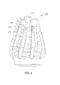
- FIG. 4 is a side view of an illustrative downhole tool having a plurality of cutting inserts coupled thereto, according to one or more embodiments of the present disclosure.
- FIG. 5 is a side view of another illustrative downhole tool having a plurality of cutting inserts coupled thereto, according to one or more embodiments of the present disclosure.
- FIG. 6 is a perspective view of yet another illustrative cutting insert, according to one or more embodiments of the present disclosure.
- FIG. 7 is a perspective view of still another illustrative cutting insert including a carbide substrate material, according to one or more embodiments of the present disclosure.
- FIG. 8 is a side view of an illustrative downhole tool having a plurality of cutting inserts coupled thereto, according to one or more embodiments of the present disclosure.
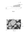
- FIG. 9 is a photograph of a composite material taken with a scanning electron microscope, according to one or more embodiments of the present disclosure.
- a cutting element e.g., cutting elements 100 , 200 , 300 , 600 , and 700 of FIGS. 1-8 .
- the cutting elements may be used for a variety of cutting operations. Such operations in which the cutting elements may be used include, but are not limited to, drilling a wellbore within a rock formation, cutting/milling a window through casing of a wellbore, drilling formation or cement after forming a window to initiate drilling of a lateral borehole, section milling a portion of casing within a wellbore, other operations, or some combination thereof.
- the cutting elements When used in a wellbore, the cutting elements may be used in connection with a downhole tool (e.g., downhole tools 400 , 500 , and 800 of FIGS. 4, 5, and 8 ).
- a downhole tool e.g., downhole tools 400 , 500 , and 800 of FIGS. 4, 5, and 8 .
- other downhole or other tools are contemplated and may be coupled to, or carry, a cutting insert according to embodiments of the present disclosure.
- Cutting elements of the present disclosure may be at least partially made from a composite material (e.g., composite material 110 of FIG. 1 ).
- the composite material may include a carbide material, a binder material, a plurality of diamond particles, other materials, or any combination of the foregoing.
- carbide material may make up between 55 wt % and 97 wt % of a total weight of the composite material.
- the binder material may make up from 3 wt % to 20 wt % of the total weight of the composite material, while the plurality of diamond particles may make up from 0.1 wt % to 25 wt % of the total weight of the composite material.
- the carbide material and the binder material may be combined and sintered together prior to being combined with the plurality of diamond particles. Combining the carbide and binder materials with the plurality of diamond particles may also be done with or without using a small or other amount of premixed metal binder or other material.
- the combined carbide and binder materials may form a plurality of pellets (e.g., pellets 910 of FIG. 9 ).
- the pellets may have an average cross-sectional length from 10 ⁇ m to 250 ⁇ m. According to at least some embodiments, the pellets may make up between 75 wt % and 99.9 wt % of the total weight of the composite material.
- the pellets may be formed of materials in addition to the carbide and binder materials.
- diamond particles may be sintered with the carbide and binder materials to form pellets.
- the size of the pellets may be between 10 ⁇ m and 500 ⁇ m.
- FIG. 1 is a perspective view of an illustrative cutting element or cutting insert 100 , according to one or more embodiments.
- the cutting insert 100 may be substantially cylindrical, and may have an outer side surface 102 and an outer end surface 104 .
- the outer end surface 104 may be substantially flat; however, as discussed in greater detail herein, the outer end surface 104 may also be curved, angled, contoured, or otherwise shaped or configured. While shown alone, it should also be appreciated that the cutting insert 100 can be used in connection with one or more other cutting inserts, and located on or in a mill, bit, reamer, or other cutting tool.
- the cutting insert 100 may be coupled to, or integral with, a directional mill, a window mill, a section mill, a reamer, a hole opener, a roller cone drill bit, an impregnated drill bit, a fixed cutter (e.g., polycrystalline diamond compact or PDC) drill bit, or other downhole tool for cutting/milling a casing or drilling into a rock formation.
- a window mill may be a mill configured to mill a window in casing made of steel or other materials.
- a section mill may be a mill configured to mill out a section of casing made of steel or other materials.
- a drill bit may be used for formation drilling.
- the cutting insert 100 may be at least partially made from a composite material 110 , which may include one or more carbide materials, one or more binder materials, a plurality of diamond particles, other materials, or any combination of the foregoing.
- the carbide material may be or include tungsten carbide (“WC”), titanium carbide (“TiC”), niobium carbide (“NbC”), tantalum carbide (“TaC”), other carbides, or any combination of the foregoing.
- the carbide material content in the composite material 110 may, in some embodiments, be within a range of 30 wt % to 99 wt % of the total weight of the composite material 110 . More particularly, the carbide material content may be within a range that includes lower and/or upper limits that include any of 30 wt %, 40 wt %, 50 wt %, 60 wt %, 70 wt %, 80 wt %, 85 wt %, 90 wt %, 95 wt %, 97 wt %, 99 wt %, or values therebetween.
- the carbide material content may be from 40 wt % to 99 wt %, from 55 wt % to 97 wt %, or from 60 wt % to 85 wt % of the total weight of the composite material 110 .
- the carbide material content may be from 40 wt % to 50 wt %, from 50 wt % to 60 wt %, from 60 wt % to 70 wt %, from 70 wt % to 80 wt %, from 70 wt % to 75 wt %, from 75 wt % to 80 wt %, from 80 wt % to 90 wt %, from 80 wt % to 85 wt %, from 85 wt % to 90 wt %, from 90 wt % to 99 wt %, from 90 wt % to 95 wt %, or from 95 wt % to 99 wt %.
- the carbide material content may be less than 30 wt % or more than 99 wt % of the total weight of the composite material 110 .
- carbide material may initially be in powder form.
- the carbide material may have a particle size or average cross-sectional length that is between 0.1 ⁇ m and 10 ⁇ m.
- the particle size may be within a range that includes lower and/or upper limits that include any of 0.1 ⁇ m, 0.5 ⁇ m, 1 ⁇ m, 1.5 ⁇ m, 2 ⁇ m, 3 ⁇ m, 4 ⁇ m, 5 ⁇ m, 7.5 ⁇ m, 10 ⁇ m, or values therebetween.
- the particle size may be from 0.1 ⁇ m to 10 ⁇ m, from 0.5 ⁇ m to 5 ⁇ m, or from 1 ⁇ m to 3 ⁇ m.
- the particle size may be from 0.1 ⁇ m to 0.5 ⁇ m, from 0.5 ⁇ m to 1 ⁇ m, from 1 ⁇ m to 3 ⁇ m, from 3 ⁇ m to 5 ⁇ m, or from 5 ⁇ m to 7.5 ⁇ m. In other embodiments, the particle size may be less than 0.1 ⁇ m or larger than 10 ⁇ m.
- the carbide material may include particles in a powder form having a particular average cross-sectional length or other particle size
- at least some of the distributions may be within a range between 0.1 ⁇ m and 10 ⁇ m.
- there may be two size distributions and 20% of the carbide materials, by weight may have a particle size between 0.5 ⁇ m and 2 ⁇ m
- 80% of the carbide materials, by weight may have a particle size between 4 ⁇ m and 6 ⁇ m.
- the composite material 110 may also include one or more binder materials.
- the one or more binder materials of the composite material 110 may include cobalt (“Co”), nickel (“Ni”), iron (“Fe”), or other metals or other materials, combinations thereof, and the like.
- the binder material content in the composite material 110 may, in some embodiments, be within a range that includes lower and/or upper limits that include any of 1 wt %, 2 wt %, 3 wt %, 4 wt %, 5 wt %, 10 wt %, 15 wt %, 20 wt %, 25 wt %, 30 wt %, or values therebetween, relative to the total weight of the composite material 110 .
- the binder material content may be from 1 wt % to 30 wt %, from 3 wt % to 20 wt %, or from 5 wt % to 15 wt % of the total weight of the composite material 110 .
- the binder material content may be from 1 wt % to 5 wt %, from 5 wt % to 10 wt %, from 10 wt % to 15 wt %, from 15 wt % to 20 wt %, or from 20 wt % to 25 wt % of the total weight of the composite material 110 .
- the composite material 110 may also include a plurality of diamond particles in some embodiments.
- the amount of the diamond particles in the composite material 110 may vary, and in some embodiments may be within a range of 0.1 wt % to 30 wt % of the total weight of the composite material 110 .
- the amount of the diamond particles may be within a range that includes lower and/or upper limits that include any of 0.1 wt %, 0.5 wt %, 1 wt %, 3 wt %, 5 wt %, 10 wt %, 15 wt %, 20 wt %, 25 wt %, 30 wt %, or any values therebetween.
- the diamond content may be from 0.1 wt % to 30 wt %, from 1 wt % to 25 wt %, from 5 wt % to 20 wt %, or from 8 wt % to 17 wt % of the total weight of the composite material 110 .
- the diamond particles may account for 0.1 wt % to 5 wt %, 5 wt % to 10 wt %, 10 wt % to 15 wt %, 15 wt % to 20 wt %, 20 wt % to 25 wt %, or 25 wt % to 30 wt % of the total weight of the composite material 110 .
- the diamond particles may account for less than 0.1 wt % or more than 30 wt % of the composite material 110 .
- a plurality of cubic boron nitride (“CBN”) particles may be used in place of, or in combination with, the diamond particles as disclosed herein. The addition of the diamond particles and/or cubic boron nitride particles may increase the wear resistance and improve the micro-chipping resistance of the cutting insert 100 .
- the particle size or average cross-sectional length of the diamond particles and/or cubic boron nitride particles may vary, and in some embodiments may range from 0.5 ⁇ m to 40 ⁇ m.
- the particle size of the diamond particles and/or cubic boron nitride particles may be within a range that includes lower and/or upper limits including any of 0.5 ⁇ m, 1 ⁇ m, 2 ⁇ m, 5 ⁇ m, 10 ⁇ m, 15 ⁇ m, 20 ⁇ m, 25 ⁇ m, 30 ⁇ m, 35 ⁇ m, 40 ⁇ m, or any values therebetween.
- the particle size may be from 1 ⁇ m to 40 ⁇ m, from 2 ⁇ m to 30 ⁇ m, or from 5 ⁇ m to 20 ⁇ m. In another embodiment, the particle size may be from 1 ⁇ m to 5 ⁇ m, from 5 ⁇ m to 10 ⁇ m, from 10 ⁇ m to 15 ⁇ m, from 15 ⁇ m to 20 ⁇ m, or from 25 ⁇ m to 30 ⁇ m. In still another embodiment, the particle size may be less than 0.5 ⁇ m or greater than 40 ⁇ m.
- the diamond particles and/or cubic boron nitride particles may include particles having a particular average cross-sectional length or other particle size
- at least some of the distributions may be within a range between 0.5 ⁇ m and 40 ⁇ m.
- there may be three size distributions and 40% of the diamond particles, by weight, may have a particle size between 0.5 ⁇ m and 5 ⁇ m
- 40% of the diamond particles, by weight may have a particle size between 10 ⁇ m and 20 ⁇ m
- 20% of the diamond particles, by weight may have a particle size between 25 ⁇ m and 40 ⁇ m.
- These percentages and ranges are, however, illustrative.
- a coating 130 may be positioned on or over at least a portion of the outer surface (e.g., outer side surface 102 and/or outer end surface 104 ) of the composite material 110 or other portion of the cutting insert 100 .
- the coating 130 may reduce the friction between the cutting insert 100 and a workpiece, such as a casing.
- the coating 130 may seal any surface defects in the cutting insert 100 , which may increase the cutting efficiency of the cutting insert 100 .
- the coating 130 may be applied in any suitable manner, including through physical vapor deposition, chemical vapor deposition, thermal spraying, ion plating, other techniques, or using combinations of the foregoing.
- the coating 130 may be placed on the outer side surface 102 of the cutting insert 100 , the outer end surface 104 of the cutting insert 100 , or both.
- the coating 130 may be or include titanium nitride (“TiN”), chromium nitride (“CrN”), titanium aluminum nitride (“TiAlN”), titanium carbide (“TiC”), titanium carbonitride (“TiCN”), silicon carbide (“SiC”), aluminum oxide (“Al 2 O 3 ”), other metals, alloys or materials, or any combination of the foregoing.
- the coating 130 may, in some embodiments, have a thickness between 0.5 ⁇ m and 30 ⁇ m.
- the thickness of the coating 130 may be within a range including lower and/or upper limits including any of 0.5 ⁇ m, 1 ⁇ m, 2 ⁇ m, 3 ⁇ m, 4 ⁇ m, 5 ⁇ m, 6 ⁇ m, 8 ⁇ m, 10 ⁇ m, 15 ⁇ m, 20 ⁇ m, or values therebetween.
- the thickness may be from 1 ⁇ m to 15 ⁇ m, from 3 ⁇ m to 10 ⁇ m, or from 4 ⁇ m to 8 ⁇ m.
- the thickness may be from 1 ⁇ m to 3 ⁇ m, from 3 ⁇ m to 5 ⁇ m, from 5 ⁇ m to 7.5 ⁇ m, from 7.5 ⁇ m to 10 ⁇ m, or from 10 ⁇ m to 15 ⁇ m. In still other embodiments, the thickness of the coating 130 may be less than 0.5 ⁇ m or more than 20 ⁇ m.
- FIG. 2 is a perspective view of another illustrative cutting insert 200 according to one or more embodiments of the present disclosure.
- the cutting insert 200 may include a composite material 110 such as that described above (i.e., including a carbide material, binder material, and a plurality of diamond particles) and a substrate material 120 .
- the composite material 110 may be a first or “upper” layer that is sintered onto, or otherwise coupled to, a second or “lower” layer of the substrate material 120 .
- the substrate material 120 may be or include a variety of materials, including carbide and/or a binder (e.g., a metal binder).
- the carbide may include tungsten carbide (“WC”), titanium carbide (“TiC”), niobium carbide (“NbC”), tantalum carbide (“TaC”), or other carbides, any combination of the foregoing, and the like.
- An included binder may be the same as the binder described above (e.g., any combination of Co, Ni, or Fe), or may have other properties.
- the binder of the substrate 120 may therefore be the same or different than a binder of the composite material 110 .
- the particle size of the components of the substrate material 120 may be substantially the same as the particle size of the components of the carbide material, or the particle size of the components of the substrate material 120 may be different.
- the height and/or thickness of the respective composite material 110 and substrate 120 may vary.
- An illustrative ratio of a height/thickness 114 of the composite material 110 to a height/thickness 116 of the substrate material 120 may be from 1:1 to 1:50.
- the ratio of height/thickness 114 of the composite material 110 to the height/thickness 116 of the substrate material 120 may be from 1:1 to 1:2, from 1:2 to 1:3, from 1:3 to 1:5, from 1:5 to 1:10, from 1:10 to 1:20, or from 1:20 to 1:50.
- a ratio of the height/thickness 114 of the composite material 110 to a height/thickness 118 of the cutting insert 200 may be from 1:1 to 1:50, or more particularly from 1:1 to 1:2, from 1:2 to 1:3, from 1:3 to 1:5, from 1:5 to 1:10, from 1:10 to 1:20, or from 1:20 to 1:50.
- the ratio of the height/thickness 114 of the composite material 110 to the height/thickness 118 of the cutting insert 200 may be 0.15:1 or 1:6.67.
- the ratio of the height/thickness 114 of the composite material 110 to a height/thickness 116 of the substrate material 120 or the cutting insert 200 may be more than 1:1 or less than 1:50.
- FIG. 3 is a cross-sectional side view of another illustrative cutting insert 300 according to some embodiments of the present disclosure.
- the cutting insert 300 may include a curved outer end surface 304 , according to one or more embodiments of the present disclosure.
- the cutting insert 300 of FIG. 3 may include the composite material 110 and the substrate material 120 , as described above with reference to FIG. 2 .
- the cutting insert 300 may include the composite material 110 without the substrate material 120 , similar to the embodiment in FIG. 1 .
- the composite material 110 of FIG. 300 may also be different than the composite material 110 of FIG. 1 and/or FIG. 2 .
- the outer end surfaces 104 of the cutting inserts 100 , 200 in FIGS. 1 and 2 may be substantially flat or planar
- the outer end surface 304 of the cutting insert 300 in FIG. 3 may optionally be contoured, curved, angled, or otherwise shaped.
- the particular embodiment shown in FIG. 3 may be referred to as a semi-round top (“SRT”) cutting insert; however, the shape of the cutting insert 300 may vary, and may have a conical top, a frustoconical top, a chisel top, a saddle top, or any other shape at the top of the cutting insert.
- the outer end surface 304 of FIG. 3 may have a radius of curvature 306 ranging from 3 mm to 20 mm.
- the radius of curvature 306 may be within a range including lower and/or upper limits that include any of 3 mm, 4 mm, 5 mm, 6 mm, 7 mm, 8 mm, 10 mm, 15 mm, 20 mm, or values therebetween.
- the radius of curvature 306 may therefore range from 3 mm to 20 mm, from 4 mm to 15 mm, from 3 mm to 4 mm, from 4 mm to 5 mm, from 6 mm to 7 mm, from 8 mm to 10 mm, or from 15 mm to 20 mm.
- the radius of curvature 306 may be less than 3 mm or more than 20 mm.
- a ratio of the radius of curvature 306 to a height 308 of the cutting insert 300 may also vary, and in some embodiments may range from 1:1 to 1:10.
- the ratio of the radius of curvature 306 to a height 308 of the cutting insert 300 may vary from 1:1 to 1:2, from 1:2 to 1:3, from 1:3 to 1:4, from 1:4 to 1:5, or from 1:5 to 1:10.
- the ratio of the radius of curvature 306 to a height 308 of the cutting insert 300 may be less than 1:1 or more than 1:10.
- the outer end surface 304 may be conical, frustoconical, chisel-shaped, or saddle-shaped.
- FIG. 4 is a side view of an illustrative cutting tool 400 having a plurality of cutting inserts 100 coupled thereto, according to one or more embodiments.
- the cutting tool 400 may include a mill.
- An example mill may include a window mill, lead mill, or taper mill for use in milling casing during a sidetracking operation.
- the particular configuration of the cutting tool 400 may, however, vary and the cutting inserts 100 may be coupled to any number of different types of tools.
- the cutting inserts 100 may instead (or additionally) be connected to any type of mill, drill bit, reamer, cutter, intervention tool, exploratory tool, or other tool.
- the cutting tool 400 , and the cutting inserts 100 may be used in a wide variety of industries such as, but not limited to, oil and gas exploration and production, water exploration and production, underground/subsea utility placement, or the like.
- the cutting tool 400 may include one or more blades 410 extending radially therefrom.
- the blades 410 may be circumferentially offset from one another with respect to a central longitudinal axis 412 through the cutting tool 400 .
- each blade 410 may include a one or more pockets 414 formed therein.
- each blade 410 may include a plurality of pockets 414 axially offset from one another with respect to the central longitudinal axis 412 through the cutting tool 400 .
- the cutting inserts 100 may be coupled to the cutting tool 400 by being positioned within the pockets 414 and secured therein via a welding, brazing, mechanical fastening, or other suitable process.
- the cutting inserts 100 may be oriented such that a central longitudinal axis 112 (see FIG. 1 ) extending therethrough is about parallel to a line that is tangential to an outer surface of the cutting tool 400 .
- FIG. 4 it should be appreciated by a person having ordinary skill in the art in view of the disclosure herein that other cutting inserts disclosed herein (e.g., cutting inserts 200 , 300 , 600 , 700 , or any combination thereof) may be used with the cutting tool 400 .
- FIG. 5 is a side view of another illustrative cutting tool 500 having a plurality of cutting inserts 300 coupled thereto, according to one or more embodiments.
- the cutting tool 500 may include a downhole, roller cone drill bit, although as described herein, the cutting tool 500 may have any number of other forms.
- the cutting tool 500 may be configured to drill a wellbore though a subterranean formation (e.g., a rock formation).
- the cutting tool 500 may include one or more cutters 510 configured to roll along the surface of the subterranean formation during drilling operations.
- the downhole tool 500 includes cutters 510 that are circumferentially offset from one another with respect to a central longitudinal axis 512 through the cutting tool 500 , and which are optionally of a substantially conical shape.
- Each conical cutter 510 may include one or more pockets 514 formed therein.
- the cutting inserts 300 may be positioned within the plurality of pockets 514 of FIG. 5 and coupled therein via a press fit, brazing, or other suitable process.
- the cutting inserts 300 may be semi-round top (“SRT”) inserts, conical top inserts, frustoconical top inserts, chisel top inserts, saddle top inserts, or the like.
- SRT semi-round top
- FIG. 6 is a cross-sectional view of yet another illustrative cutting insert 600 , according to one or more embodiments of the present disclosure.
- the cutting insert 600 may have opposing inner and outer surfaces 602 , 604 .
- the inner surface 602 may be substantially flat or planar.
- the outer surface 604 may be a serrated, textured, ridged, or otherwise configured.
- the cutting insert 600 may be made at least partially from a composite material (e.g., composite material 110 including a carbide material, binder material, and plurality of diamond particles as described herein).
- FIG. 7 is a perspective view of yet another illustrative cutting insert 700 .
- the cutting insert 700 includes an optional substrate material 120 , according to one or more embodiments.
- the cutting insert 700 of FIG. 7 may be similar to the cutting insert 600 of FIG. 6 ; however, the cutting insert 700 of FIG. 7 may also include the substrate material 120 .
- the composite material 110 may be a first or “outer” layer that is sintered or otherwise adhered, bonded, or otherwise coupled to a second or “inner” layer of the substrate material 120 .
- the substrate material 120 may be similar to the substrate material 120 described above with reference to FIG. 2 , and may include a carbide material in some embodiments.
- a ratio of a height/thickness 124 of the composite material 110 to a height/thickness 126 of the substrate material 120 may be from 5:1 to 1:50 in some embodiments.
- the ratio of a height/thickness 124 of the composite material 110 to a height/thickness 126 of the substrate material 120 may be from 5:1 to 3:1, from 3:1 to 2:1, from 2:1 to 1:1, from 1:1 to 1:2, from 1:2 to 1:3, from 1:3 to 1:5, from 1:5 to 1:10, or from 1:10 to 1:50.
- the ratio of the height/thickness 124 of the composite material 110 to the height/thickness 126 of the substrate material 120 may be greater than 5:1 or less than 1:50 in other embodiments.
- a ratio of the height/thickness 124 of the composite material 110 to a height/thickness 128 of the cutting insert 700 may also vary. In some embodiments, for instance, the ratio may be from 1:1 to 1:50. For instance, a ratio of the height/thickness 124 of the composite material 110 to a height/thickness 128 of the cutting insert 700 may be from 1:1 to 1:1.5, from 1:1.5 to 1:2, from 1:2 to 1:3, from 1:3 to 1:5, from 1:5 to 1:10, from 1:10 to 1:20, or from 1:20 to 1:50. In other embodiments, the ratio of the height/thickness 124 of the composite material 110 to the height/thickness 128 of the cutting insert 700 may be less than 1:50.
- FIG. 8 is a top view of an illustrative blade 800 that may be used in a cutting tool (e.g., a downhole tool for a section mill to cut casing) according to one or more embodiments.
- the blade 800 may include a plurality of the cutting inserts 600 coupled thereto or integral therewith.
- the cutting inserts 600 may be welded, brazed, or otherwise coupled to the blade 800 .
- the inserts 600 are shown, it may be appreciated that the inserts 100 , 200 , 300 , 600 , 700 , or any combination thereof, may be used with the blade 800 .
- carbide materials, binder materials, diamond particles, or any combination of the foregoing may initially be in a powder form having the particle sizes described above.
- the carbide material, the binder material, and the diamond particles (each in powder form) may be mixed together in suitable proportions, including the proportions described herein.
- the mixed powders may then be sintered to form the composite material.
- the mixed powders and substrate may be assembled with a pre-shaped can or mold and sintered therein such that the composite material 110 is in the shape of the cutting insert 100 , 200 , 300 , 600 , 700 (or relevant portion thereof) shown in, or described with reference to, any one of FIGS. 1-8 .
- the temperature of a suitable sintering process may range from 1200° C. to 1700° C. in some embodiments.
- the temperature of the sintering process may be within a range including lower and/or upper limits that include any of 1200° C., 1250° C., 1300° C., 1350° C., 1400° C., 1500° C., 1550° C., 1600° C., 1650° C., 1700° C., or temperatures therebetween.
- the sintering temperature may be from 1300° C. to 1600° C. or from 1400° C. to 1500° C. In other embodiments, the temperature may be less than 1200° C. or more than 1700° C.
- the pressure of a suitable sintering process may also vary, and in some embodiments may range from 3000 MPa to 8000 MPa. More particularly, the pressure of the sintering process may be within a range including lower and/or upper limits including any of 3000 MPa, 3500 MPa, 4000 MPa, 4500 MPa, 5000 MPa, 6000 MPa, 6500 MPa, 7000 MPa, 7500 MPa, 8000 MPa, or values therebetween. For example, the pressure may be between 3000 MPa and 7000 MPa, between 4000 MPa and 6000 MPa, or between 4500 MPa and 5500 MPa. In other embodiments, the pressure of the sintering process may be less than 3000 MPa or more than 8000 MPa.
- the composite material 110 may be on and/or coupled to a substrate material 120 , as shown in FIGS. 2, 3, and 7 . More particularly, the composite material 110 may be sintered or otherwise coupled to the substrate material 120 to form the cutting inserts 200 , 300 , 700 . In other embodiments, however, the substrate material 120 may be omitted, as shown in FIGS. 1 and 6 .
- FIG. 9 is a photograph of an example of a composite material as disclosed herein (e.g., composite material 110 of FIG. 1-3, 6 , or 7 ), as taken with a scanning electron microscope, according to one or more embodiments.
- a carbide material and a binder material may be mixed together prior to the addition of the diamond particles.
- the carbide material and the binder material may be sintered to form a plurality of pellets 910 .
- the pellets 910 may have a substantially spherical shape, an angled shape, or any other suitable shape.
- the pellets 910 may have a particle size or average cross-sectional length ranging from 10 ⁇ m to 300 ⁇ m in some embodiments.
- the pellets 910 may have a particle size or average cross-sectional length within a range with lower and/or upper limits including any 10 ⁇ m, 20 ⁇ m, 30 ⁇ m, 40 ⁇ m, 50 ⁇ m, 75 ⁇ m, 100 ⁇ m, 150 ⁇ m, 200 ⁇ m, 250 ⁇ m, 300 ⁇ m, or values therebetween.
- the size of the pellets 910 may be from 10 ⁇ m to 250 ⁇ m, from 20 ⁇ m to 200 ⁇ m, from 50 ⁇ m to 180 ⁇ m, or from 75 ⁇ m to 150 ⁇ m.
- the size of the pellets 910 may be from 10 ⁇ m to 50 ⁇ m, from 30 ⁇ m to 70 ⁇ m, from 50 ⁇ m to 90 ⁇ m, from 70 ⁇ m to 110 ⁇ m, from 90 ⁇ m to 130 ⁇ m, from 110 ⁇ m to 150 ⁇ m, from 130 ⁇ m to 170 ⁇ m, from 150 ⁇ m to 190 ⁇ m, or from 170 ⁇ m to 210 ⁇ m.
- the size of the pellets 910 may be less than 10 ⁇ m or more than 300 ⁇ m.
- the pellets 910 , the plurality of diamond particles, and optionally a binder may be mixed together and sintered to form the composite material.
- a binder e.g., metal binder
- the pellets 910 , the diamond particles, and a pre-mixed cobalt powder may be assembled (e.g., in the proportions described herein) with the substrate into a can or a mold and sintered therein such that the composite material is in the shape of a desired cutting insert 100 , 200 , 300 , 600 , 700 (or relevant portion thereof) shown in any one of FIGS. 1-8 .
- the binder material may be the same material as the binder material used to form the pellets 910 (e.g., cobalt), or may be different.
- the plurality of diamond particles may form a diamond network 912 .
- the pellets 910 may be located or dispersed in the diamond network 912 . At least one of the pellets 910 may be surrounded by the diamond network 912 such that the pellet 910 is not in contact with another pellet 910 .
- a hardness of the composite material may range from HV900 to HV4000 in some embodiments.
- the hardness of the composite material 110 may be within range including lower and/or upper limits including any of HV900, HV1070, HV1400, HV1700, HV1900, HV2140, HV2700, HV3300, HV4000, or values therebetween.
- the hardness of the composite material may be from HV1250 to HV4000, from HV1550 to HV3600, or from HV1700 to HV3100.
- the hardness of the composite material may be less than HV900 or more than HV4000.
- the microstructure of the composite material shown in FIG. 9 may provide a cutting insert (e.g., cutting insert 100 , 200 , 300 , 600 , 700 of FIGS. 1-8 ) having a high compressive strength, a high wear resistance, an increased toughness, other mechanical properties, or some combination of the foregoing.
- a cutting insert including the composite material shown in FIG. 9 may form self-sharpening edges.
- the diamond network 912 may chip and/or wear down before the pellets 910 , as the diamond network 912 reacts with the steel and/or graphitizes. This may cause the pellets 910 to be exposed with sharp edges, which may enhance cutting efficiency.
- Relational terms such as “bottom,” “below,” “top,” “above,” “back,” “front,” “left,” “right,” “rear,” “forward,” “up,” “down,” “horizontal,” “vertical,” “clockwise,” “counterclockwise,” “upper,” “lower,” “uphole,” “downhole,” and the like, may be used to describe various components, including their operation and/or illustrated position relative to one or more other components. Relational terms do not indicate a particular orientation for each embodiment within the scope of the description or claims.
- a component of a cutting tool, cutting insert, or bottomhole assembly that is described as “below” another component may be further from the surface while within a vertical wellbore or when oriented on a mill or other bit, but may have a different orientation during assembly, when removed from the wellbore or bit, or in a lateral borehole.
- relational descriptions are intended solely for convenience in facilitating reference to various components, but such relational aspects may be reversed, flipped, rotated, moved in space, placed in a diagonal orientation or position, placed horizontally or vertically, or similarly modified.
- Certain descriptions or designations of components as “first,” “second,” “third,” and the like may also be used to differentiate between identical components or between components which are similar in use, structure, or operation. Such language is not intended to limit a component to a singular designation.
- a component referenced in the specification as the “first” component may be the same or different than a component that is referenced in the claims as a “first” component.
- Couple refers to “in direct connection with,” or “in connection with via one or more intermediate elements or members.”
- Components that are “integral” or “integrally” formed include components made from the same piece of material, or sets of materials, such as by being commonly molded or cast from the same material, or machined from the same one or more pieces of material stock. Components that are “integral” should also be understood to be “coupled” together.
- While embodiments disclosed herein may be used in oil, gas, or other hydrocarbon exploration or production environments, such environments are merely illustrative. Systems, tools, assemblies, methods, cutting tools, cutting inserts, mills, drill bits, composite materials, substrates, and other components of the present disclosure, or which would be appreciated in view of the disclosure herein, may be used in other applications and environments. In other embodiments, milling tools, cutting inserts, or other embodiments discussed herein, or which would be appreciated in view of the disclosure herein, may be used outside of a downhole environment, including in connection with other systems, including within automotive, aquatic, aerospace, hydroelectric, manufacturing, medical, other industries, or even in other downhole environments.
- well wellbore
- borehole and the like are therefore also not intended to limit embodiments of the present disclosure to a particular industry.
- a wellbore or borehole may, for instance, be used for oil and gas production and exploration, water production and exploration, mining, utility line placement, or myriad other applications.
- the stated values include at least experimental error and variations that would be expected by a person having ordinary skill in the art, as well as the variation to be expected in a suitable manufacturing or production process.
- a value that is about or approximately the stated value and is therefore encompassed by the stated value may further include values that are within 10%, within 5%, within 1%, within 0.1%, or within 0.01% of a stated value.
Abstract
Description
Claims (18)
Priority Applications (1)
| Application Number | Priority Date | Filing Date | Title |
|---|---|---|---|
| US14/487,942 US9856702B2 (en) | 2013-09-18 | 2014-09-16 | Cutting element for a downhole tool |
Applications Claiming Priority (2)
| Application Number | Priority Date | Filing Date | Title |
|---|---|---|---|
| US201361879555P | 2013-09-18 | 2013-09-18 | |
| US14/487,942 US9856702B2 (en) | 2013-09-18 | 2014-09-16 | Cutting element for a downhole tool |
Publications (2)
| Publication Number | Publication Date |
|---|---|
| US20150075878A1 US20150075878A1 (en) | 2015-03-19 |
| US9856702B2 true US9856702B2 (en) | 2018-01-02 |
Family
ID=52666946
Family Applications (1)
| Application Number | Title | Priority Date | Filing Date |
|---|---|---|---|
| US14/487,942 Active 2036-02-29 US9856702B2 (en) | 2013-09-18 | 2014-09-16 | Cutting element for a downhole tool |
Country Status (1)
| Country | Link |
|---|---|
| US (1) | US9856702B2 (en) |
Families Citing this family (1)
| Publication number | Priority date | Publication date | Assignee | Title |
|---|---|---|---|---|
| DE102016200911A1 (en) * | 2016-01-22 | 2017-07-27 | Thyssenkrupp Ag | Wear protection element for a shredding device |
Citations (15)
| Publication number | Priority date | Publication date | Assignee | Title |
|---|---|---|---|---|
| EP0123288A1 (en) | 1983-04-22 | 1984-10-31 | LES CABLES DE LYON Société anonyme dite: | Process for manufacturing an optical fibre cable |
| US4515226A (en) | 1983-03-07 | 1985-05-07 | Norton Christensen, Inc. | Tooth design to avoid shearing stresses |
| US6612383B2 (en) | 1998-03-13 | 2003-09-02 | Smith International, Inc. | Method and apparatus for milling well casing and drilling formation |
| EP1218556B1 (en) | 1999-09-24 | 2004-06-23 | 3M Innovative Properties Company | Fused abrasive bodies comprising an oxygen scavenger metal |
| US7211218B2 (en) | 2000-03-09 | 2007-05-01 | Smith International, Inc. | Polycrystalline diamond carbide composites |
| US7350955B2 (en) * | 2005-03-09 | 2008-04-01 | Hannstar Display Corporation | Back light source module |
| US7350599B2 (en) | 2004-10-18 | 2008-04-01 | Smith International, Inc. | Impregnated diamond cutting structures |
| US20100243336A1 (en) | 2009-03-27 | 2010-09-30 | Varel International, Ind., L.P. | Backfilled polycrystalline diamond cutter with high thermal conductivity |
| US8006781B2 (en) | 2008-12-04 | 2011-08-30 | Baker Hughes Incorporated | Method of monitoring wear of rock bit cutters |
| EP2176499B1 (en) | 2007-06-15 | 2011-12-21 | Baker Hughes Incorporated | Cutting element for subterranean drilling |
| US20120005966A1 (en) | 2010-07-06 | 2012-01-12 | Baker Hughes Incorporated | Methods of forming inserts and earth-boring tools |
| US20120152622A1 (en) * | 2010-12-15 | 2012-06-21 | National Oilwell DHT, L.P. | In-Situ Boron Doped PDC Element |
| US8267204B2 (en) | 2009-08-11 | 2012-09-18 | Baker Hughes Incorporated | Methods of forming polycrystalline diamond cutting elements, cutting elements, and earth-boring tools carrying cutting elements |
| US20120247840A1 (en) | 2011-03-30 | 2012-10-04 | Baker Hughes Incorporated | Methods of forming earth boring tools and related structures |
| US8397841B1 (en) | 2000-05-01 | 2013-03-19 | Smith International, Inc. | Drill bit with cutting elements having functionally engineered wear surface |
-
2014
- 2014-09-16 US US14/487,942 patent/US9856702B2/en active Active
Patent Citations (15)
| Publication number | Priority date | Publication date | Assignee | Title |
|---|---|---|---|---|
| US4515226A (en) | 1983-03-07 | 1985-05-07 | Norton Christensen, Inc. | Tooth design to avoid shearing stresses |
| EP0123288A1 (en) | 1983-04-22 | 1984-10-31 | LES CABLES DE LYON Société anonyme dite: | Process for manufacturing an optical fibre cable |
| US6612383B2 (en) | 1998-03-13 | 2003-09-02 | Smith International, Inc. | Method and apparatus for milling well casing and drilling formation |
| EP1218556B1 (en) | 1999-09-24 | 2004-06-23 | 3M Innovative Properties Company | Fused abrasive bodies comprising an oxygen scavenger metal |
| US7211218B2 (en) | 2000-03-09 | 2007-05-01 | Smith International, Inc. | Polycrystalline diamond carbide composites |
| US8397841B1 (en) | 2000-05-01 | 2013-03-19 | Smith International, Inc. | Drill bit with cutting elements having functionally engineered wear surface |
| US7350599B2 (en) | 2004-10-18 | 2008-04-01 | Smith International, Inc. | Impregnated diamond cutting structures |
| US7350955B2 (en) * | 2005-03-09 | 2008-04-01 | Hannstar Display Corporation | Back light source module |
| EP2176499B1 (en) | 2007-06-15 | 2011-12-21 | Baker Hughes Incorporated | Cutting element for subterranean drilling |
| US8006781B2 (en) | 2008-12-04 | 2011-08-30 | Baker Hughes Incorporated | Method of monitoring wear of rock bit cutters |
| US20100243336A1 (en) | 2009-03-27 | 2010-09-30 | Varel International, Ind., L.P. | Backfilled polycrystalline diamond cutter with high thermal conductivity |
| US8267204B2 (en) | 2009-08-11 | 2012-09-18 | Baker Hughes Incorporated | Methods of forming polycrystalline diamond cutting elements, cutting elements, and earth-boring tools carrying cutting elements |
| US20120005966A1 (en) | 2010-07-06 | 2012-01-12 | Baker Hughes Incorporated | Methods of forming inserts and earth-boring tools |
| US20120152622A1 (en) * | 2010-12-15 | 2012-06-21 | National Oilwell DHT, L.P. | In-Situ Boron Doped PDC Element |
| US20120247840A1 (en) | 2011-03-30 | 2012-10-04 | Baker Hughes Incorporated | Methods of forming earth boring tools and related structures |
Also Published As
| Publication number | Publication date |
|---|---|
| US20150075878A1 (en) | 2015-03-19 |
Similar Documents
| Publication | Publication Date | Title |
|---|---|---|
| US10309157B2 (en) | Cutting element incorporating a cutting body and sleeve and an earth-boring tool including the cutting element | |
| US10267096B2 (en) | Drill bit rolling element with retaining ring | |
| US11396776B2 (en) | Multiple ridge cutting element | |
| US9957757B2 (en) | Cutting elements for drill bits for drilling subterranean formations and methods of forming such cutting elements | |
| US11156036B2 (en) | Polycrystalline diamond cutting elements with transition zones and downhole cutting tools incorporating the same | |
| US9187962B2 (en) | Methods of attaching rolling cutters in fixed cutter bits using sleeve, compression spring, and/or pin(s)/ball(s) | |
| EP2823127B1 (en) | Cutting elements retained within sleeves | |
| CA2828866C (en) | Methods of forming polycrystalline elements and structures formed by such methods | |
| US10151149B2 (en) | Rolling cutter assemblies | |
| US20100038148A1 (en) | Intermetallic Aluminide Polycrystalline Diamond Compact (PDC) Cutting Elements | |
| US20140326516A1 (en) | Rolling cutter with side retention | |
| US20140360792A1 (en) | Split sleeves for rolling cutters | |
| RU2017133614A (en) | SUPER-SOLID STRUCTURES AND METHODS FOR PRODUCING THEM | |
| US10774594B2 (en) | Rotating cutting structures and structures for retaining the same | |
| GB2464640A (en) | A cutting element having layers including diamond of different grain sizes. | |
| IE86590B1 (en) | Shear cutter with improved wear resistance of WC-CO substrate | |
| US20120199402A1 (en) | Infiltrated diamond wear resistant bodies and tools | |
| US9988853B2 (en) | Retention of multiple rolling cutters | |
| US20160168917A1 (en) | Cutting element with varied substrate length | |
| US9856702B2 (en) | Cutting element for a downhole tool | |
| GB2587458A (en) | A cutting element and methods of making same | |
| US10641046B2 (en) | Cutting elements with geometries to better maintain aggressiveness and related earth-boring tools and methods | |
| US10753156B2 (en) | Cutting element backing support |
Legal Events
| Date | Code | Title | Description |
|---|---|---|---|
| AS | Assignment |
Owner name: SMITH INTERNATIONAL, INC., TEXAS Free format text: ASSIGNMENT OF ASSIGNORS INTEREST;ASSIGNORS:XIA, SIKE;DENG, XIN;SIGNING DATES FROM 20141104 TO 20141117;REEL/FRAME:034192/0548 |
|
| STCF | Information on status: patent grant |
Free format text: PATENTED CASE |
|
| AS | Assignment |
Owner name: WELLBORE INTEGRITY SOLUTIONS LLC, TEXAS Free format text: ASSIGNMENT OF ASSIGNORS INTEREST;ASSIGNOR:SMITH INTERNATIONAL, INC.;REEL/FRAME:051470/0680 Effective date: 20191231 |
|
| AS | Assignment |
Owner name: WELLS FARGO BANK, NATIONAL ASSOCIATION, AS COLLATERAL AGENT, NORTH CAROLINA Free format text: ABL PATENT SECURITY AGREEMENT;ASSIGNOR:WELLBORE INTEGRITY SOLUTIONS LLC;REEL/FRAME:052184/0900 Effective date: 20191231 |
|
| MAFP | Maintenance fee payment |
Free format text: PAYMENT OF MAINTENANCE FEE, 4TH YEAR, LARGE ENTITY (ORIGINAL EVENT CODE: M1551); ENTITY STATUS OF PATENT OWNER: LARGE ENTITY Year of fee payment: 4 |
|
| AS | Assignment |
Owner name: WELLBORE INTEGRITY SOLUTIONS LLC, TEXAS Free format text: RELEASE BY SECURED PARTY;ASSIGNOR:WELLS FARGO BANK, NATIONAL ASSOCIATION;REEL/FRAME:056910/0165 Effective date: 20210715 |