JP4611368B2 - DC / DC converter device, vehicle, fuel cell system, and driving method of DC / DC converter device - Google Patents
DC / DC converter device, vehicle, fuel cell system, and driving method of DC / DC converter device Download PDFInfo
- Publication number
- JP4611368B2 JP4611368B2 JP2007330920A JP2007330920A JP4611368B2 JP 4611368 B2 JP4611368 B2 JP 4611368B2 JP 2007330920 A JP2007330920 A JP 2007330920A JP 2007330920 A JP2007330920 A JP 2007330920A JP 4611368 B2 JP4611368 B2 JP 4611368B2
- Authority
- JP
- Japan
- Prior art keywords
- arm
- phase
- turned
- converter
- arm element
- Prior art date
- Legal status (The legal status is an assumption and is not a legal conclusion. Google has not performed a legal analysis and makes no representation as to the accuracy of the status listed.)
- Expired - Fee Related
Links
Images


Classifications
-
- Y—GENERAL TAGGING OF NEW TECHNOLOGICAL DEVELOPMENTS; GENERAL TAGGING OF CROSS-SECTIONAL TECHNOLOGIES SPANNING OVER SEVERAL SECTIONS OF THE IPC; TECHNICAL SUBJECTS COVERED BY FORMER USPC CROSS-REFERENCE ART COLLECTIONS [XRACs] AND DIGESTS
- Y02—TECHNOLOGIES OR APPLICATIONS FOR MITIGATION OR ADAPTATION AGAINST CLIMATE CHANGE
- Y02T—CLIMATE CHANGE MITIGATION TECHNOLOGIES RELATED TO TRANSPORTATION
- Y02T10/00—Road transport of goods or passengers
- Y02T10/60—Other road transportation technologies with climate change mitigation effect
- Y02T10/64—Electric machine technologies in electromobility
Landscapes
- Dc-Dc Converters (AREA)
- Electric Propulsion And Braking For Vehicles (AREA)
Description
この発明は、直流電圧を昇降圧するDC/DCコンバータ装置と、このDC/DCコンバータ装置が搭載された車両又は燃料電池システム及びDC/DCコンバータ装置の駆動方法に関する。 The present invention relates to a DC / DC converter device that steps up and down a DC voltage, a vehicle or a fuel cell system in which the DC / DC converter device is mounted, and a driving method of the DC / DC converter device.
従来から、MOSFETあるいはIGBT等のスイッチング素子を用いたスイッチング電源であるDC/DCコンバータ装置が広汎に利用されている。 Conventionally, DC / DC converter devices, which are switching power supplies using switching elements such as MOSFETs or IGBTs, have been widely used.
例えば、走行駆動源としてモータを用いる車両の一形態として、蓄電装置とインバータ駆動モータとの間に直流電圧を昇降圧するDC/DCコンバータ装置が介装された車両(ここでは、電気自動車という。)が提案されている。この電気自動車では、モータの駆動時に、DC/DCコンバータ装置により蓄電装置の電圧を昇圧してインバータに印加し、モータの回生時には、インバータに発生する回生電圧をDC/DCコンバータ装置により降圧して蓄電装置側に印加して充電等する。 For example, as one form of a vehicle using a motor as a travel drive source, a vehicle (herein referred to as an electric vehicle) in which a DC / DC converter device for stepping up / down a DC voltage is interposed between a power storage device and an inverter drive motor. Has been proposed. In this electric vehicle, when the motor is driven, the voltage of the power storage device is boosted by the DC / DC converter device and applied to the inverter, and during regeneration of the motor, the regenerative voltage generated in the inverter is stepped down by the DC / DC converter device. The battery is charged by being applied to the power storage device side.
また、走行駆動源としてモータを用いる車両の他の形態として、燃料電池とインバータ駆動モータとを直接接続し、この接続点と蓄電装置との間に直流電圧を昇降圧するDC/DCコンバータ装置が介装され、燃料電池を主電源装置とし、蓄電装置を前記主電源装置をアシストする従電源装置とした車両(ここでは、燃料電池車両という。)も提案されている。 Further, as another form of vehicle using a motor as a travel drive source, a DC / DC converter device that directly connects a fuel cell and an inverter drive motor and steps up / down a DC voltage between the connection point and the power storage device is provided. There has also been proposed a vehicle (herein referred to as a fuel cell vehicle) in which a fuel cell is used as a main power supply device and a power storage device is a sub power supply device that assists the main power supply device.
この燃料電池車両では、モータの駆動時に、燃料電池の電圧とDC/DCコンバータ装置により昇圧した蓄電装置の電圧とを併合してインバータに印加し、モータの回生時には、インバータに発生する回生電圧をDC/DCコンバータ装置により降圧して蓄電装置側に印加して充電等する。また、燃料電池の発生電力に余剰分があるとき、降圧して蓄電装置側に印加して充電等する。 In this fuel cell vehicle, when the motor is driven, the voltage of the fuel cell and the voltage of the power storage device boosted by the DC / DC converter device are combined and applied to the inverter, and when the motor is regenerated, the regenerative voltage generated in the inverter is applied. The voltage is stepped down by the DC / DC converter device, applied to the power storage device side, and charged. Further, when there is a surplus in the generated power of the fuel cell, it is stepped down, applied to the power storage device side, and charged.
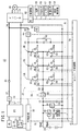
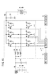
図15は、電気自動車に適用される特許文献1に開示されたDC/DCコンバータ装置16を示している。このDC/DCコンバータ装置16は、基本的には、リアクトル2A、2B、2C(2A〜2C)と、ダイオード7A、7B、7C(7A〜7C)、8A、8B、8C(8A〜8C)がトランジスタ3A、3B、3C(3A〜3C)、4A、4B、4C(4A〜4C)に逆並列接続されたスイッチング部とからなるDC/DCコンバータ6と、DC/DCコンバータ6を駆動制御する制御手段5とから構成される。
FIG. 15 shows a DC /
DC/DCコンバータ装置16は、低圧側TLの直流電源1の電圧をm倍昇圧して高圧側THの負荷11に印加する電圧に変換する機能と、逆に高圧側THの電圧をm分の1に降圧して低圧側TLの直流電源1に印加する機能を合わせ持つ。
The DC /
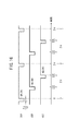
このDC/DCコンバータ装置16は、図16に示すように、昇圧時に、スイッチング周期2π中、例えば、デューティが92≒{(11/12)×100}[%]で駆動されると、3相アーム中、下アーム素子の各トランジスタ4A〜4Cが制御手段5からの駆動信号ULA、ULB、ULC(ULA〜ULC)によって位相が2π/3ずれた状態でオンされる。
As shown in FIG. 16, when the DC /
各トランジスタ4A〜4Cがオンされているときには、各リアクトル2A〜2Cの各トランジスタ4A〜4C側が接地されることになるので、各リアクトル2A〜2Cには直流電源1から電流が接地に向かって流れる。このとき各リアクトル2A〜2Cには、流れる電流の2乗と各リアクトル2A〜2Cのインダクタンスの積に比例するエネルギが蓄えられる。
When the
次に、各トランジスタ4A〜4CがオンからOFFになると、リアクトル2A〜2Cに蓄えられたエネルギに応じた電流がダイオード7A〜7Cを通じて高圧側THに流れる。このとき高圧側THの電圧は電圧検出回路6aによって監視されている。
Next, when each of the
一方、降圧時には、3相アーム中、上アーム素子の各トランジスタ3A〜3Cが制御手段5からの駆動信号UHA、UHB、UHC(UHA〜UHC)によって位相が2π/3ずれた状態で順次オンされる。各トランジスタ3A〜3Cがオンされることにより高圧側THからトランジスタ3A〜3C及びリアクトル2A〜2Cを通って低圧側TLの直流電源1へと電流が流れ、リアクトル2A〜2Cにエネルギが蓄えられる。
On the other hand, at the time of step-down, in the three-phase arm, the
次に、各トランジスタ3A〜3Cが順次OFFとされると、ダイオード8A〜8Cが対応して順次オンされ、接地からダイオード8A〜8C及びリアクトル2A〜2Cを通じて直流電源1に電流が流れる降圧回路として動作する。
Next, when each of the
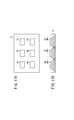
ところで、DC/DCコンバータ装置16では、スイッチング素子として大電力用のトランジスタが採用され、3相アームの場合には、図17Aの平面視に示すように、金属製の放熱板(ヒートスプレッダ)12上に6個のトランジスタ3A〜3C、4A〜4Cが固定される構造とされる。
By the way, in the DC /
上記のDC/DCコンバータ装置16では、図16に示したように、スイッチング周期2πの間で、9/12の時間で3個のトランジスタが同時オン状態となっており、残りの3/12の時間で2個のトランジスタが同時オン状態になっている。
In the DC /
しかしながら、図17Bに示すように、3個のトランジスタが同時にオン状態になっている場合には、ハッチングで示す各トランジスタからの熱の伝達の様子中、ダブルハッチングとなる部分で熱が集中し、きわめて放熱効率が悪くなる。トランジスタの最高許容温度等の熱的条件を満足させるためには、ヒートスプレッダ12の体積と表面積を増加するとともに、このヒートスプレッダ12を冷却する冷却水の流量を増加させる必要があり、結果としてDC/DCコンバータ装置16の大きさが大型になるという問題がある。
However, as shown in FIG. 17B, when three transistors are turned on at the same time, heat is concentrated at the portion where double hatching occurs in the state of heat transfer from each transistor indicated by hatching, The heat dissipation efficiency is extremely poor. In order to satisfy the thermal conditions such as the maximum allowable temperature of the transistor, it is necessary to increase the volume and surface area of the
この発明はこのような課題を考慮してなされたものであり、放熱性に優れたDC/DCコンバータ装置、並びにこのDC/DCコンバータ装置が適用された車両、燃料電池システム及びDC/DCコンバータ装置の駆動方法を提供することを目的とする。 The present invention has been made in consideration of such problems, and has a DC / DC converter device excellent in heat dissipation, and a vehicle, a fuel cell system, and a DC / DC converter device to which the DC / DC converter device is applied. An object of the present invention is to provide a driving method.
この発明に係るDC/DCコンバータ装置は、第1電力装置と第2電力装置との間に、上アーム素子と下アーム素子からなる複数の相アームが並列的に接続された多相アームのDC/DCコンバータと、複数の前記相アームを1スイッチング周期毎に交替してオンするとともに、前記相アームをオンするとき、該相アームを構成する前記上アーム素子又は前記下アーム素子の一方をオンするか交互にオンする制御部と、前記上アーム素子と前記下アーム素子の素子温度を測定する温度センサと、を備え、前記制御部は、複数の前記相アームを1スイッチング周期毎に交替してオンする際、ある相アームの前記上アーム素子と前記下アーム素子とを交互にオンした後、次の相アームの前記上アーム素子と前記下アーム素子とを交互にオンし、前記相アームを構成する前記上アーム素子又は前記下アーム素子を交互にオンするとき、デッドタイムを挟んで交互にオンし、かつ前記多相アームを構成する前記相アームを、デッドタイムを挟んで交替してオンする全アーム素子によるローテーションスイッチング駆動を行い、さらに、前記相アームをオンしようとするとき、素子温度が閾値より高い前記上アーム素子のオンを休止するが、休止した当該上アーム素子に直列に接続され相互に相アームを構成する下アーム素子に対するオン駆動信号の供給は停止せず、又は素子温度が閾値より高い前記下アーム素子のオンを休止するが、休止した当該下アーム素子に直列に接続され相互に相アームを構成する上アーム素子に対するオン駆動信号の供給は停止しないで、素子温度が前記閾値温度より低くなり正常範囲に復帰したところで、前記全アーム素子によるローテーションスイッチング駆動を再び行うことを特徴とする(請求項1)。 The DC / DC converter device according to the present invention is a multiphase arm DC in which a plurality of phase arms composed of an upper arm element and a lower arm element are connected in parallel between a first power device and a second power device. The DC / DC converter and the plurality of phase arms are alternately turned on every switching period, and when the phase arm is turned on, one of the upper arm element or the lower arm element constituting the phase arm is turned on. A control unit that turns on or turns on and a temperature sensor that measures element temperatures of the upper arm element and the lower arm element, and the control unit alternates a plurality of the phase arms for each switching period. When turning on, the upper arm element and the lower arm element of a certain phase arm are alternately turned on, and then the upper arm element and the lower arm element of the next phase arm are alternately turned on. When the upper arm element or the lower arm element constituting the phase arm is alternately turned on, the phase arm is alternately turned on with the dead time interposed therebetween, and the phase arm constituting the multiphase arm is replaced with the dead time interposed. Rotation switching drive is performed by all arm elements that are turned on , and when the phase arm is to be turned on, the upper arm element whose element temperature is higher than a threshold is paused, but the paused upper arm element is The supply of the ON drive signal to the lower arm elements that are connected in series and mutually constitute phase arms does not stop, or the on-off of the lower arm element whose element temperature is higher than the threshold value is stopped , The supply of the ON drive signal to the upper arm elements that are connected in series and mutually constitute a phase arm does not stop, and the element temperature is the threshold temperature. Ri becomes in was returned to the normal range low, and performs the rotation switching driving by full arm element again (claim 1).
この発明に係るDC/DCコンバータ装置の駆動方法は、第1電力装置と第2電力装置との間に、素子温度を測定する温度センサを備える上アーム素子と下アーム素子からなる複数の相アームが並列的に接続された多相アームのDC/DCコンバータの前記相アームをオンする際、複数の前記相アームを1スイッチング周期毎に交替してオンするとともに、前記相アームをオンするとき、該相アームを構成する前記上アーム素子又は前記下アーム素子の一方をオンするか交互にオンする手順と、複数の前記相アームを1スイッチング周期毎に交替してオンする際、ある相アームの前記上アーム素子と前記下アーム素子とを交互にオンした後、次の相アームの前記上アーム素子と前記下アーム素子とを交互にオンする手順と、前記相アームを構成する前記上アーム素子又は前記下アーム素子を交互にオンするとき、デッドタイムを挟んで交互にオンし、かつ前記多相アームを構成する前記相アームを、デッドタイムを挟んで交替してオンする全アーム素子によるローテーションスイッチング駆動を行う手順と、前記相アームをオンしようとするとき、素子温度が閾値より高い前記上アーム素子のオンを休止するが、休止した当該上アーム素子に直列に接続され相互に相アームを構成する下アーム素子に対するオン駆動信号の供給は停止せず、又は素子温度が閾値より高い前記下アーム素子のオンを休止するが、休止した当該下アーム素子に直列に接続され相互に相アームを構成する上アーム素子に対するオン駆動信号の供給は停止しないで、素子温度が前記閾値温度より低くなり正常範囲に復帰したところで、前記全アーム素子によるローテーションスイッチング駆動を再び行う手順と、を含むことを特徴とする(請求項8)。 A method for driving a DC / DC converter device according to the present invention includes a plurality of phase arms each including an upper arm element and a lower arm element having a temperature sensor for measuring an element temperature between a first power device and a second power device. When turning on the phase arm of the DC / DC converter of the multi-phase arm connected in parallel, the plurality of phase arms are switched on every switching period, and when the phase arm is turned on, When one of the upper arm element and the lower arm element constituting the phase arm is turned on or alternately turned on, and when the plurality of phase arms are alternately turned on every switching period, A procedure for alternately turning on the upper arm element and the lower arm element of the next phase arm after alternately turning on the upper arm element and the lower arm element, and configuring the phase arm. When turned on alternately the upper arm element or the lower arm element, alternately turned on with dead time, and the phase arms constituting said polyphase arm, turned on in alternation with dead time Procedure for performing rotation switching drive by all arm elements and when turning on the phase arm, the upper arm element whose element temperature is higher than a threshold value is turned on, but is connected in series to the suspended upper arm element. The supply of the ON drive signal to the lower arm elements constituting the mutual phase arm does not stop, or the ON state of the lower arm element whose element temperature is higher than the threshold is stopped, but is connected in series to the stopped lower arm element. The supply of the ON drive signal to the upper arm elements constituting the mutual phase arm does not stop, and the element temperature is lower than the threshold temperature and normal. Now that has returned to the circumference, characterized in that it comprises a, a step of performing rotation switching drive again by the entire arm device (claim 8).
この発明に係るDC/DCコンバータ装置並びにその駆動方法によれば、上アーム素子及び下アーム素子が同時にオンされることがなく、かつ異なる相アームが同時にオンされることがない。したがって、常時、多くても1つのスイッチング素子がオン状態とされるのみである。よって、放熱性に優れる(放熱設計が容易である)。結果として、DC/DCコンバータ装置の大きさを小型化し、かつ重量を軽量化することができる。 According to the DC / DC converter device and the driving method thereof according to the present invention, the upper arm element and the lower arm element are not simultaneously turned on, and different phase arms are not simultaneously turned on. Therefore, at most one switching element is always turned on. Therefore, it has excellent heat dissipation (heat dissipation design is easy). As a result, the size of the DC / DC converter device can be reduced and the weight can be reduced.
ここで、上記発明は、DC/DCコンバータに接続される前記第2電力装置を、回生電圧を発生するインバータ駆動の走行用モータとし、前記第1電力装置を蓄電装置とした、車両(電気自動車、内燃機関と蓄積装置を有するハイブリッド車両)に適用することができる(請求項5)。 Here, in the above invention, the second electric power device connected to the DC / DC converter is an inverter-driven travel motor that generates a regenerative voltage, and the first electric power device is a power storage device. it can be applied to a hybrid vehicle) having an internal combustion engine and storage device (claim 5).
また、上記発明は、DC/DCコンバータに接続される前記第2電力装置を、回生電圧を発生するインバータ駆動の走行用モータと該走行用モータを駆動する燃料電池とされ、前記第1電力装置を蓄電装置とした、車両(燃料電池車両)に適用することができる(請求項6)。 In the above invention, the second power device connected to the DC / DC converter is an inverter-driven travel motor that generates a regenerative voltage and a fuel cell that drives the travel motor, and the first power device It was used as the power storage device can be applied to the vehicle (fuel cell vehicle) (claim 6).
さらに、上記発明は、DC/DCコンバータに接続される前記第2電力装置を燃料電池とし、前記第1電力装置を蓄電装置として負荷を駆動する燃料電池システムに適用することができる(請求項7)。 Furthermore, the invention, the second power device connected to the DC / DC converter and the fuel cell can be applied to the first power unit in the fuel cell system for driving a load as an electric storage device (claim 7 ).
なお、複数の前記相アームを交替してオンする際、1スイッチング周期毎に交替してオンするようにしているので、制御が容易になる(請求項1)。n(nは、2以上の整数)スイッチング周期毎に交替してオンするようにしてもよい。 Note that when turned on by alternating a plurality of said phase arm, than are such that they are turned on by alternating every switching cycle, the control is facilitated (claim 1). n (n is an integer of 2 or more) may be switched on every switching cycle.
この場合、前記制御部は、前記相アームを構成する前記上アーム素子又は前記下アーム素子を交互にオンするときデッドタイムを挟んで交互にオンし、かつ前記多相アームを構成する前記相アームをデッドタイムを挟んで交替してオンするようにしているので、上アーム素子と下アーム素子との短絡及び相アーム間の短絡を防止することができる(請求項1)。 In this case, the control unit turns on alternately with a dead time when alternately turning on the upper arm element or the lower arm element constituting the phase arm, and the phase arm constituting the polyphase arm the than with alternate with dead time has to be turned on, it is possible to prevent short circuit and short-circuit between phases arm and upper arm device and the lower arm device (claim 1).
さらに、前記上アーム素子と前記下アーム素子の素子温度を測定する温度センサを備え、前記制御部は、前記相アームをオンしようとする際、素子温度が閾値より高い上アーム素子又は下アーム素子のオンを休止するように制御しているので、放熱設計が容易になる(放熱板を小さくすることができる)(請求項1)。 Furthermore, a temperature sensor for measuring element temperatures of the upper arm element and the lower arm element is provided, and when the control unit tries to turn on the phase arm, the upper arm element or the lower arm element whose element temperature is higher than a threshold value Therefore , the heat radiation design is facilitated (the heat radiation plate can be made smaller) (Claim 1 ).
昇降圧用のリアクトルとして1個で、この発明を実施することができる(請求項2)。もちろん相分のリアクトルを利用してこの発明を実施することもできる(請求項3)。 In one as a reactor for the buck-boost, it can be utilized to effect this invention (claim 2). Of course, the present invention can also be implemented by using the reactor of the phase (claim 3) .
前記多相アームが3相アームである場合、前記3相アームを構成する上下アーム素子合計6個を、1つの放熱板上に固定した構成とすることで、放熱板の設計が容易である(請求項3)。
When the multiphase arm is a three-phase arm, a total of six upper and lower arm elements constituting the three-phase arm are fixed on one heat sink, so that the heat sink can be easily designed ( Claim 3 ).
この発明によれば、相アームを構成する上アーム素子及び下アーム素子が同時にオンされることがなく、かつ異なる相アームが同時にオンされることがない。したがって、常時、多くても1つのスイッチング素子がオン状態とされるのみである。よって、放熱性に優れたDC/DCコンバータ装置、並びにこのDC/DCコンバータ装置が適用された車両、燃料電池システム及びDC/DCコンバータ駆動方法を実現することができる。 According to the present invention, the upper arm element and the lower arm element constituting the phase arm are not simultaneously turned on, and different phase arms are not simultaneously turned on. Therefore, at most one switching element is always turned on. Therefore, it is possible to realize a DC / DC converter device excellent in heat dissipation, and a vehicle, a fuel cell system, and a DC / DC converter driving method to which the DC / DC converter device is applied.
結果として、DC/DCコンバータ装置の大きさを小型化し、かつ重量を軽量化することができる。 As a result, the size of the DC / DC converter device can be reduced and the weight can be reduced.
以下、この発明に係るDC/DCコンバータ装置の駆動方法を実施するDC/DCコンバータ装置が適用された車両等の実施形態について図面を参照して説明する。 DESCRIPTION OF EMBODIMENTS Hereinafter, embodiments of a vehicle or the like to which a DC / DC converter device that implements a method for driving a DC / DC converter device according to the present invention is applied will be described with reference to the drawings.
図1に示すこの実施形態に係る燃料電池車両20は、基本的には、燃料電池22とエネルギストレージである蓄電装置(バッテリという。)24とから構成されるハイブリッド型の電源装置と、このハイブリッド型の電源装置から電流(電力)がインバータ34を通じて供給される走行用のモータ26と、バッテリ24が接続される1次側1Sと燃料電池22とモータ26(インバータ34)とが接続される2次側2Sとの間で電圧変換を行うDC/DCコンバータ装置{VCU(Voltage Control Unit)という。}23とから構成される。
A
VCU23は、DC/DCコンバータ36と、これを駆動制御するコンバータ制御部54とから構成される。
The
燃料電池22は、例えば固体高分子電解質膜をアノード電極とカソード電極とで両側から挟み込んで形成されたセルを積層したスタック構造にされている。燃料電池22には、水素タンク28とエアコンプレッサ30が配管により接続されている。燃料電池22内で反応ガスである水素(燃料ガス)と空気(酸化剤ガス)の電気化学反応により生成された発電電流Ifは、電流センサ32及びダイオード(ディスコネクトダイオードともいう。)33を介して、インバータ34及び(又は)DC/DCコンバータ36に供給される。
The
インバータ34は、直流/交流変換を行い、モータ電流Imをモータ26に供給する一方、回生動作に伴う交流/直流変換後のモータ電流Imを2次側2SからDC/DCコンバータ36を通じて1次側1Sに供給する。
The
この場合、回生電圧又は発電電圧Vfである2次電圧V2がDC/DCコンバータ36により低電圧に変換された1次電圧V1は、ダウンバータ42により降圧されてさらに低電圧とされ、ランプ等の補機44に補機電流Iauとして供給されるとともに、余剰分があればバッテリ電流Ibatとしてバッテリ24を充電する。
In this case, the primary voltage V1 obtained by converting the secondary voltage V2 which is the regenerative voltage or the generated voltage Vf into a low voltage by the DC /
1次側1Sに接続されるバッテリ24は、例えばリチウムイオン2次電池又はキャパシタを利用することができる。この実施形態ではリチウムイオン2次電池を利用している。
As the
バッテリ24は、ダウンバータ42を通じて補機44に補機電流Iauを供給するとともに、DC/DCコンバータ36を通じてインバータ34にモータ電流Imを供給する。
The
1次側1S及び2次側2Sには、それぞれ平滑用のコンデンサ38、39が設けられている。2次側2Sのコンデンサ39には、並列に、すなわち燃料電池22に対しても並列に、抵抗器40が接続されている。
燃料電池22を含むシステムはFC制御部50により制御され、インバータ34とモータ26を含むシステムはインバータ駆動部を含むモータ制御部52により制御され、DC/DCコンバータ36を含むシステムはコンバータ駆動部を含むコンバータ制御部54により、それぞれ基本的に制御される。
The system including the
そして、これらFC制御部50、モータ制御部52、及びコンバータ制御部54は、上位の制御部であり燃料電池22の総負荷量Lt等を決定する統括制御部56により制御される。
The
統括制御部56、FC制御部50、モータ制御部52、及びコンバータ制御部54は、それぞれCPU、ROM、RAM、タイマの他、A/D変換器、D/A変換器等の入出力インタフェース、並びに、必要に応じてDSP(Digital Signal Processor)等を有している。
The
統括制御部56、FC制御部50、モータ制御部52、及びコンバータ制御部54は、車内LANであるCAN(Controller Area Network)等の通信線70を通じて相互に接続され、各種スイッチ及び各種センサからの入出力情報を共有し、これら各種スイッチ及び各種センサからの入出力情報を入力として各CPUが各ROMに格納されたプログラムを実行することにより各種機能を実現する。
The
ここで、車両状態を検出する各種スイッチ及び各種センサとしては、発電電流Ifを検出する電流センサ32の他、1次電圧V1(バッテリ電圧Vbatに等しい。)を検出する電圧センサ61、1次電流I1を検出する電流センサ62、2次電圧V2(ディスコネクトダイオード33が導通しているとき、略燃料電池22の発電電圧Vfに等しい。)を検出する電圧センサ63、2次電流I2を検出する電流センサ64、通信線70に接続されるイグニッションスイッチ65、アクセルセンサ66,ブレーキセンサ67、車速センサ68、並びにコンバータ制御部54に接続される温度センサ69等がある。
Here, as various switches and various sensors for detecting the vehicle state, in addition to the
統括制御部56は、燃料電池22の状態、バッテリ24の状態、モータ26の状態、及び補機44の状態の他、各種スイッチ及び各種センサからの入力(負荷要求)に基づき決定した燃料電池車両20の総負荷要求量Ltから、燃料電池22が負担すべき燃料電池分担負荷量(要求出力)Lfと、バッテリ24が負担すべきバッテリ分担負荷量(要求出力)Lbと、回生電源が負担すべき回生電源分担負荷量Lrの配分(分担)を調停しながら決定し、FC制御部50、モータ制御部52及びコンバータ制御部54に指令を送出する。
The
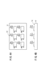
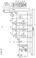
DC/DCコンバータ36は、バッテリ24(第1電力装置)と第2電力装置{燃料電池22又は回生電源(インバータ34とモータ26)}との間に、それぞれIGBT等のスイッチング素子からなる上アーム素子81{81u、81v、81w(81u〜81w)}と、下アーム素子82{82u、82v、82w(82u〜82w)}とからなる3つの相アーム{U相アームUA(81u、82u)、V相アームVA(81v、82v)、W相アームWA(81w、82w)}が並列的に接続された3相アームとして構成されている。
The DC /
各アーム素子81u、81v、81w、82u、82v、82wには、それぞれ、逆方向にダイオード83u、83v、83w、84u、84v、84wが接続されている。
理解の便宜等を考慮し、この発明においては、上アーム素子81及び下アーム素子82には逆並列ダイオード83、84が含まれないものとする。 In consideration of convenience of understanding and the like, in the present invention, it is assumed that the upper arm element 81 and the lower arm element 82 do not include the antiparallel diodes 83 and 84.
DC/DCコンバータ36により1次電圧V1と2次電圧V2との間で電圧を変換する際に、エネルギを放出及び蓄積する1個のリアクトル90が、3相アームの各相のアーム(U相アームUA、V相アームVA、W相アームWA)の中点の共通接続点とバッテリ24との間に挿入されている。
When the voltage is converted between the primary voltage V1 and the secondary voltage V2 by the DC /
上アーム素子81(81u〜81w)は、コンバータ制御部54から出力されるゲートの駆動信号(駆動電圧)UH、VH、WH(のハイレベル)によりそれぞれオンにされ、下アーム素子82(82u〜82w)は、ゲートの駆動信号(駆動電圧)UL、VL、WL(のハイレベル)によりそれぞれオンにされる。
The upper arm elements 81 (81u to 81w) are turned on by gate drive signals (drive voltages) UH, VH, and WH (high levels thereof) output from the
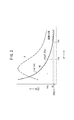
1次電圧V1、代表的には、負荷が接続されていないときのバッテリ24の開放電圧OCV(Open Circuit Voltage)は、図2の燃料電池出力特性(電流電圧特性)91上に示すように、この燃料電池22の発電電圧Vfの最低電圧Vfminより高い電圧に設定されている。なお、図2において、OCV≒V1としている。
The primary voltage V1, typically the open circuit voltage OCV (Open Circuit Voltage) of the
2次電圧V2は、燃料電池22が発電動作しているときには燃料電池22の発電電圧Vfに等しい電圧にされる。
The secondary voltage V2 is set to a voltage equal to the power generation voltage Vf of the
ただし、燃料電池22の発電電圧Vfがバッテリ24の電圧Vbat(=V1)に等しくなったときには、図2に一点鎖線の太線で示す直結状態とされる。直結状態では、上アーム素子81(81u〜81w)に供給される駆動信号UH、VH、WHのデューティが100[%]にされ、2次側2Sから1次側1Sへ電流が流れる場合には上アーム素子81(81u〜81w)がオンにされて該上アーム素子81(81u〜81w)を通じて電流が流れ、1次側1Sから2次側2Sへ電流が流れる場合にはダイオード83u〜83wが導通して該ダイオード83u〜83wを通じて電流が流れる。高出力時にDC/DCコンバータ36の2次側2Sから2次電流I2をインバータ34側に供給する{ソース(source)するという。}直結状態(高出力時直結状態又は第1直結状態という。)では、2次電圧V2がV2=V1−Vd(Vdは、ダイオード83u、83v、83wの順方向電圧降下)になる。
However, when the power generation voltage Vf of the
なお、直結状態は、高出力領域に限らず、制御上必要な場合に利用される。例えば、燃料電池車両20の停車時に直結状態を利用できる。燃料電池車両20の停車時(信号待ち等)には、燃費節約のために、エアコンプレッサ30の駆動が停止され、水素タンク28からの燃料ガスの供給も停止される。この場合、燃料電池22の発電電圧Vf(発電電流If)は抵抗器40等によるディスチャージ及びエアコンディショナ等の補機44への供給により燃料電池22内の残留燃料ガスが消尽するとゼロ値となるが、補機44への補機電流Iauの供給はバッテリ24により継続される。
The direct connection state is used not only in the high output area but also when necessary for control. For example, the direct connection state can be used when the
このような燃料電池車両20を停車時、いわゆるアイドル停止時からブレーキペダル操作の解除、アクセルペダル操作等により燃料電池22を発電状態へ復帰させるときに、VCU23による燃料電池22の出力制御を円滑に再開するために、DC/DCコンバータ36の2次側2Sの電圧を直結状態の電圧に保持しておく。この直結状態(アイドル停止直結状態又は第2直結状態という。)においては、負荷が抵抗器40とされ、DC/DCコンバータ36の2次側2Sの電圧V2がV2=V1−Vdに保持される。
When the
ここで、VCU23による燃料電池22の出力制御について説明する。
Here, output control of the
水素タンク28からの燃料ガス及びエアコンプレッサ30からの圧縮空気が供給されている発電時に、燃料電池22の発電電流Ifは、図2に示した特性91{関数F(Vf)という。}上で2次電圧V2、すなわち発電電圧Vfをコンバータ制御部54によりDC/DCコンバータ36を通じて設定することにより決定される。つまり、発電電流Ifは、発電電圧Vfの関数F(Vf)値として決定される。If=F(Vf)であり、例えば発電電圧VfをVf=Vfa=V2と設定すれば、その発電電圧Vfa(V2)の関数値としての発電電流Ifaが決定される。{Ifa=F(Vfa)=F(V2)}。
During power generation in which fuel gas from the
このように燃料電池22は二次電圧V2(発電電圧Vf)を決定することにより発電電流Ifが決定されるので、燃料電池車両20を駆動制御する際には、2次電圧V2(発電電圧Vf)が目標電圧(目標値)に設定される。ただし、ダウンバータ42とバッテリ24間の配線の断線故障等によりバッテリ24が開放状態にされる等、バッテリ24(第1電力装置)が故障とみなされる特殊な場合には、1次電圧V1が目標電圧とされる。
Since the
燃料電池車両20等燃料電池22を含むシステムでは、DC/DCコンバータ36の2次側2Sの2次電圧V2が目標電圧となるようにVCU23が制御され、このVCU23により燃料電池22の出力(発電電流If)が制御される。以上が、VCU23による燃料電池22の出力制御の説明である。
In the system including the
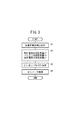
次に、コンバータ制御部54により駆動制御されるDC/DCコンバータ36の基本動作について図3のフローチャートを参照して説明する。
Next, the basic operation of the DC /
上述したように、統括制御部56は、燃料電池22の状態、バッテリ24の状態、モータ26の状態、及び補機44の状態の他、各種スイッチ及び各種センサからの入力(負荷要求)に基づき決定した燃料電池車両20の総負荷要求量Ltから、燃料電池22が負担すべき燃料電池分担負荷量(要求出力)Lfと、バッテリ24が負担すべきバッテリ分担負荷量(要求出力)Lbと、回生電源が負担すべき回生電源分担負荷量Lrの配分(分担)を調停しながら決定し、FC制御部50、モータ制御部52及びコンバータ制御部54に指令を送出する。
As described above, the
ステップS1において、統括制御部56により、それぞれが負荷要求であるモータ26の電力要求と補機44の電力要求とエアコンプレッサ30の電力要求から総負荷要求量Ltが決定(算出)されると、ステップS2において、統括制御部56は、決定した総負荷要求量Ltを出力するための燃料電池分担負荷量Lfと、バッテリ分担負荷量Lbと、回生電源分担負荷量Lrの配分を決定する。ここで、燃料電池分担負荷量Lfを決定する場合、燃料電池22の効率ηが考慮される。
In step S1, when the total load request amount Lt is determined (calculated) from the power request of the
次いで、ステップS3において、コンバータ制御部54により、燃料電池分担負荷量Lfに応じて燃料電池22の発電電圧Vf、ここでは、2次電圧V2が決定される。
Next, in step S3, the
2次電圧V2が決定されると、ステップS4において、コンバータ制御部54は、決定した2次電圧V2となるようにDC/DCコンバータ36を駆動制御する。
When the secondary voltage V2 is determined, in step S4, the
この場合、コンバータ制御部54は、決定した2次電圧V2に応じて、DC/DCコンバータ36を昇圧動作、降圧動作又は直結動作で駆動する。
In this case, the
ステップS4において、DC/DCコンバータ36の2次側2Sからインバータ34側へ2次電流I2をソースする昇圧動作では、コンバータ制御部54は、下アーム素子82uオン(リアクタンス90にバッテリ電流Ibatから補機電流Iauを差し引いた1次電流I1によりエネルギを蓄積すると同時に、コンデンサ39から2次電流I2をインバータ34へソースする。以下同様)→ダイオード83u〜83w導通(リアクタンス90からエネルギ放出しコンデンサ39にエネルギを蓄積するとともに、2次電流I2としてインバータ34へソースする。以下同様)→下アーム素子82vオン→ダイオード83u〜83w導通→下アーム素子82wオン→ダイオード83u〜83w導通→下アーム素子82uオン…の順でDC/DCコンバータ36をローテーションスイッチングする。
In step S4, in the step-up operation in which the secondary current I2 is sourced from the
なお、上アーム素子81u〜81w及び下アーム素子82u〜82wのオンデューティは、出力電圧V2が保持されるように決定される。
The on-duty of the
また、ステップS4において、DC/DCコンバータ36の2次側2Sからインバータ34側へ2次電流I2をソースする高出力直結動作では、ダイオード83u〜83wが導通状態となって2次電圧V2がV2=V1−Vdとなる。
In step S4, in the high output direct connection operation in which the secondary current I2 is sourced from the
さらに、ステップS4において、DC/DCコンバータ36の2次側2Sから1次側1Sの補機44やバッテリ24に2次電流I2を供給する(2次側2Sでは、シンク(sink)するという。)降圧動作では、上アーム素子81uオン(リアクタンス90にコンデンサ39から出力される2次電流I2によりエネルギを蓄積するとともにコンデンサ38から補機44及び要求に応じてバッテリ24に1次電流I1を供給する。以下同様)→ダイオード84u〜84w導通(ダイオード84u〜84wはフライホイールダイオードとして導通し、リアクタンス90からエネルギ放出され、コンデンサ38にエネルギを蓄積するとともに補機44及び要求に応じてバッテリ24に1次電流I1を供給する。以下同様)→上アーム素子81vオン→ダイオード84u〜84w導通→上アーム素子81wオン→ダイオード84u〜84w導通→上アーム素子81uオン…の順でDC/DCコンバータ36をローテーションスイッチングする。
Further, in step S4, the secondary current I2 is supplied from the
回生電圧が存在する場合、この降圧動作時に回生電源分担負荷量Lrがシンクされる2次電流に加算される。この降圧動作における上アーム素子81u〜81w及び下アーム素子82u〜82wのオンデューティも、決定された出力電圧V2に応じて制御される。
When a regenerative voltage is present, the regenerative power source shared load Lr is added to the sinked secondary current during the step-down operation. The on-duty of the
2次電圧V2及び1次電圧V1は、コンバータ制御部54によりDC/DCコンバータ36をフィードフォワード制御とフィードバック制御とを組み合わせたPID制御により制御される。
The secondary voltage V <b> 2 and the primary voltage V <b> 1 are controlled by the
以上が、コンバータ制御部54により駆動制御されるDC/DCコンバータ36の基本動作の説明である。
The above is the description of the basic operation of the DC /
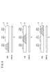
図4A、図4Bに示すように、各アーム素子81u〜81w、82u〜82wは、金属製の放熱板(ヒートスプレッダ)12上に固定された、いわゆる6in1モジュール13とされている。各アーム素子81u〜81w、82u〜82wには、温度センサ69が取り付けられ、各温度センサ69及び各アーム素子81u〜81w、82u〜82wのゲート端子は、コンバータ制御部54に接続されている。なお、各アーム素子81u〜81w、82u〜82wと対になっているダイオード83u〜83w、84u〜84wについては図示を省略している。
As shown in FIGS. 4A and 4B, the
この実施形態に係る燃料電池車両20は、モータ26を駆動するインバータ34として、DC/DCコンバータ36と同一構成の前記6in1モジュール13を利用しているので、コスト削減が可能である。
Since the
ただし、インバータ34によりモータ26を駆動する際、インバータ34の3相アームの各中点は共通接続されず、各中点がモータ26のU相コイル、V相コイル、W相コイルに接続されたフルブリッジの構成にされる。
However, when the
この実施形態に係る燃料電池車両20は、基本的には以上のように構成されかつ動作するものであり、次に、DC/DCコンバータ36を含むVCU23によるローテーションスイッチングの動作についてより詳しく説明する。
The
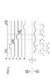
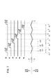
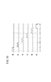
図5にVCU23の降圧動作時(2次電流I2のシンク時)のタイムチャート、図6にVCU23の昇圧動作時(2次電流I2のソース時)のタイムチャートを示す。 FIG. 5 shows a time chart during the step-down operation of the VCU 23 (when sinking the secondary current I2), and FIG. 6 shows a time chart during the step-up operation of the VCU 23 (when the secondary current I2 is sourced).
図5及び図6において、リアクトル90に流れる1次電流I1の符号は、1次側1Sから2次側2Sへ流れる昇圧時電流(DC/DCコンバータ23の2次側2Sからインバータ34へ流れ出すソース電流)を正(+)、2次側2Sから1次側1Sへ流れる降圧時電流(燃料電池22又はインバータ34から2次側2Sへ流れ込むシンク電流)を負(−)に取っている。
5 and 6, the sign of the primary current I1 flowing through the
また、コンバータ制御部54から出力される駆動信号UH、UL、VH、VL、WH、WLの波形中、ハッチングを付けた期間は、駆動信号UH、UL、VH、VL、WH、WLが供給されているアーム素子(例えば、駆動信号UHに対応するアーム素子は上アーム素子81u)が実際にオンしている(電流が流れている)期間を示している。つまり、駆動信号UH、UL、VH、VL、WH、WLが供給されていても、該当する並列ダイオード83u〜83w、84u〜84wがOFFになっていなければ該当するアーム素子に電流が流れないことに留意する。
Further, in the waveforms of the drive signals UH, UL, VH, VL, WH, WL output from the
図5及び図6に示すように、DC/DCコンバータ36の降圧動作及び昇圧動作のいずれの場合にも、コンバータ制御部54から出力される駆動信号UH、UL、VH、VL、WH、WLの波形から理解されるように、3相アームを構成するUVW各相アームUA、VA、WA(UA〜WA)を1スイッチング周期2π毎に、駆動信号UH、UL、VH、VL、WH、WLをU相、V相、W相、U相、…と交替(ローテーション)してオンするとともに、UVW各相アームUA〜WAをオンするとき、駆動信号UH、VH、WHによりUVW各相アームUA〜WAを構成する上アーム素子81(81u〜81w)をオン(図5)又は駆動信号UL、VL、WLによりUVW各相アームUA〜WAを構成する下アーム素子82(82u〜82w)をオン(図6)している。
As shown in FIGS. 5 and 6, the drive signals UH, UL, VH, VL, WH, WL output from the
この場合、図5、図6及び後述する図7から分かるように、上下アーム素子81、82間が同時にオンして電圧V2が短絡することを防止するために、上アーム素子81u〜81w又は下アーム素子82u〜82wを交互にオンするための駆動信号UHと駆動信号UL、駆動信号VHと駆動信号VL、及び駆動信号WHと駆動信号WLとの間でそれぞれデッドタイムdtを挟んでオンし、かつ多相アームを構成する相アームUA〜UWを交替してオンするとき駆動信号ULと駆動信号VHとの間、駆動信号VLと駆動信号WHとの間、及び駆動信号WLと駆動信号UHとの間にそれぞれデッドタイムdtを挟んでオンするようにしている。すなわち、デッドタイムdtを挟んで、いわゆる同期スイッチングを行っている。
In this case, as can be seen from FIGS. 5 and 6 and FIG. 7 described later, the
降圧動作を説明する図5において、例えば、時点t1〜t2の間で駆動信号UHにより上アーム素子81uがオンしている期間には、燃料電池22及び(又は)回生電源による2次電流I2により上アーム素子81uを通じてリアクトル90にエネルギが蓄積される。時点t2〜t5までのデッドタイムdt、駆動信号ULがオン(ただし、下アーム素子82uには電流が流れない。)及びデッドタイムdtの期間では、リアクトル90に蓄積されたエネルギが、フライホイールダイオードとして機能しオンとなっているダイオード84u〜84wを通じて1次側1Sに1次電流I1として放出される。時点t5以降、順次、上アーム素子81v、81w、81u、…がオンし、同様の動作を繰り返す。
In FIG. 5 for explaining the step-down operation, for example, during the period in which the
昇圧動作を説明する図6において、例えば、時点t13〜t14の間で駆動信号ULにより下アーム素子82uがオンしている期間には、バッテリ24からの1次電流I1によりリアクトル90にエネルギが蓄積される。時点t14〜t17までのデッドタイムdt、駆動信号VHがオン(ただし、上アーム素子81vには電流が流れない。)及びデッドタイムdtの期間では、リアクトル90に蓄積されたエネルギが、整流ダイオードとして機能しオンとなったダイオード83u〜83wを通じて2次側2Sに放出される。時点t17以降、順次、下アーム素子82v、82w、82u、…がオンし、同様の動作を繰り返す。
In FIG. 6 for explaining the step-up operation, for example, energy is accumulated in the
なお、昇圧動作と降圧動作の移り変わり(遷移)時の動作を説明する図7において、例えば、時点t20〜t21の間で駆動信号UHにより上アーム素子81uがオンしている期間(ハッチングで示す期間)には、燃料電池22及び(又は)回生電源による2次電流I2により上アーム素子81uを通じてリアクトル90にエネルギが蓄積される。
In FIG. 7 for explaining the operation at the time of transition between the step-up operation and the step-down operation, for example, a period during which the
時点t21から電流の流れる向きが反転する(符号が負から正に反転する)時点t22までの期間では、リアクトル90に蓄積されたエネルギが、オンとなったフライホイールダイオードとして機能するダイオード84u〜84wを通じて1次側1Sに放出される。
During the period from time t21 to the time t22 when the direction of current flow is reversed (the sign is reversed from negative to positive), the energy stored in the
時点t22〜t23の間で駆動信号ULにより下アーム素子82uがオンしている期間では、バッテリ24からの1次電流I1によりリアクトル90にエネルギが蓄積される。時点t23から電流の流れる向きが反転する(符号が正から負に反転する)時点t24までの期間では、リアクトル90に蓄積されたエネルギが、オンとなったダイオード83u〜83wを通じて2次側2Sに放出される。以下、同様の動作を繰り返す。このように、この実施形態に係る3相ローテーションスイッチングでは、昇圧動作と降圧動作との間で動作が滑らかに移り変わる。
During a period in which the
以上説明したように上述した実施形態によれば、VCU23は、燃料電池22とインバータ34の接続点である2次側2Sと、バッテリ24が接続された1次側1Sとの間に、上アーム素子81と下アーム素子82からなる相アームUA〜WAが3相並列的に接続された3相アームからなるDC/DCコンバータ36とこのDC/DCコンバータ36を駆動制御するコンバータ制御部54とを備える。
As described above, according to the above-described embodiment, the
コンバータ制御部54は、3相アームからなるDC/DCコンバータ36の相アームUA〜WAをオンする際、図5〜図7を参照して説明したように、3相アームを構成するUVW相アームUA〜WAを交替してオンし、交替してオンする際、ある相アーム、例えばU相アームUAの上アーム素子81uをオンした(図5〜図7)後、U相アームUAの下アーム素子82uをオンし(図7)、その後、次の相であるV相アームVAの上アーム素子81vをオンした後(図5〜図7)、V相アームVAの下アーム素子82vの順にオンする(図7)というように、スイッチングタイミングをローテーションしている。
When the
図8は、3相アームをU相オン→V相オン→W相オン→U相オン…とローテーションしてスイッチングしたときの各アーム素子81u〜81w、82u〜82wの放熱状態の模式図を示す。
FIG. 8 is a schematic diagram of the heat dissipation state of each of the
図8から分かるように、ローテーションスイッチングでは、一時に1つの上アーム素子81又は下アーム素子82のみをオンするようにしているので、ハッチングで示す放熱経路から理解されるように、図17Bにダブルハッチングで示したような重なり部分(放熱板12の表面積をオーバーラップして使用する部分)が発生しないことから放熱性が向上する。その結果、6in1モジュール13の小型・軽量化が図れる。
As can be seen from FIG. 8, in rotation switching, only one upper arm element 81 or lower arm element 82 is turned on at a time. Since there is no overlapping portion (portion where the surface area of the
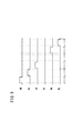
図9は、3相ローテーションの他の実施形態に係る駆動信号UH、UL、VH、VL、WH、WLのタイムチャートを示す。 FIG. 9 shows a time chart of drive signals UH, UL, VH, VL, WH, WL according to another embodiment of three-phase rotation.
この他の実施形態では、全駆動信号UH、UL、VH、VL、WH、WLをローテーションしないで駆動信号VLを休止したローテーションスイッチングとしている。図4Aに示したように全アーム素子81u、81v、81w、82u、82v、82wの素子温度を測定する温度センサ69を備えているので、素子温度が閾値温度より高い下アーム素子82vの駆動を一時的に休止し、残りのアーム素子81u、81v、81w、82u、82wでローテーションスイッチングを継続する。素子温度が閾値温度より低くなり正常範囲に復帰したところで全アーム素子81u、81v、81w、82u、82v、82wによる3相ローテーションスイッチング駆動を再び行う。休止する駆動信号は1アームに限定されない。例えば、駆動信号UH、VH、VLを休止させてもよい。
In this other embodiment, rotation switching is performed in which the drive signal VL is stopped without rotating all the drive signals UH, UL, VH, VL, WH, and WL. As shown in FIG. 4A, since the
図9例に示した間欠的なローテーションスイッチングは、ある相アームに開放等の故障を発生したとき、その故障した相アームを動作させずに、他の相アームだけでスイッチングを継続する用途に適用することができる。この動作を持つことで、VCU23、ひいては燃料電池車両20の信頼度を上げることができる。
The intermittent rotation switching shown in the example of Fig. 9 is applied to the application in which switching is continued only with another phase arm without operating the failed phase arm when a failure such as opening occurs in a certain phase arm. can do. By having this operation, the reliability of the
このように、この発明では、相アームUA〜WAを交替してオンするが、相アームUA〜WAを交替してオンするとき、相アームUA〜WAを構成する上アーム素子81(81u、81v、81wのいずれか)又は下アーム素子82(82u、82v、82wのいずれか)のいずれか一方をオンするように制御する。 As described above, in the present invention, the phase arms UA to WA are switched on and turned on, but when the phase arms UA to WA are switched on, the upper arm elements 81 (81u, 81v constituting the phase arms UA to WA) are switched on. , 81w) or the lower arm element 82 (any one of 82u, 82v, 82w) is controlled to be turned on.
なお、多相アームを構成する相アームUA〜WAを交替してオンする際、ある相の上アーム素子81u〜81wと下アーム素子82u〜82wとを順序を問わずに交互にオンした後、次の相アームの上アーム素子81u〜81wと下アーム素子82u〜82wとを順序を問わずに交互にオンすることができる。また相アームUA〜WAを交替でオンする際、1スイッチング周期2π毎に交替してオンするように制御することで制御が容易になる。2スイッチング周期4π以上の周期毎に相アームUA〜WAを交替でオンするように制御してもよい。
When the phase arms UA to WA constituting the multiphase arm are alternately turned on, the
図10の変形例に示すように、1スイッチング周期2π中に、上アーム素子81及び(又は)下アーム素子82u〜82wを複数回オンすることもこの発明に含まれる。
As shown in the modification of FIG. 10, the present invention includes turning on the upper arm element 81 and / or the
以上説明したように、上述した実施形態によれば、上アーム素子81(81u〜81w)と下アーム素子82(82u〜82w)とが同時にオンされることがなく、かつ異なる相アームUA〜WAが同時にオンされることもない。したがって、常時、多くても1つのアーム素子(スイッチング素子)がオン状態とされるのみである。よって、放熱性に優れる(放熱設計が容易である)。 As described above, according to the embodiment described above, the upper arm element 81 (81u to 81w) and the lower arm element 82 (82u to 82w) are not simultaneously turned on, and different phase arms UA to WA are used. Are not turned on at the same time. Therefore, at most, at most one arm element (switching element) is always turned on. Therefore, it has excellent heat dissipation (heat dissipation design is easy).
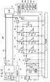
なお、この発明は、3相のDC/DCコンバータ36ではなく、図11に示すように、2相のDC/DCコンバータ36Aとした燃料電池車両20Aにも適用することができる。2相以上であれば、4相以上であっても、この発明を適用することができる。
The present invention can be applied not to the three-phase DC /
また、燃料電池車両20、20Aではなく、図12に示すように、バッテリ駆動車両(電気自動車)21に適用することもできる。もちろん、エンジンとバッテリとモータを搭載した、いわゆるパラレル方式又はシリーズパラレル方式のハイブリッド自動車にも適用することもできる。
Further, the present invention can be applied not to the
さらに、モータ26は、車両用に限らない。例えばエレベータ昇降用等のモータにも適用することもできる。
Furthermore, the
さらにまた、図13に示すように、インバータ34を単相の負荷35に代替する他、モータ制御部52を負荷制御部53に代替し、イグニッションスイッチ65を電源スイッチ65aに代替し、各種センサ66a、67a、68aに代替した燃料電池システム20Bに適用することもできる。統括制御部56は、コンバータ制御部54を通じてVCU23を制御し、結果として負荷電流ILを制御する。
Furthermore, as shown in FIG. 13, in addition to replacing the
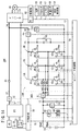
また、図14に示すように、UVW各相アームUA〜UWの中点にそれぞれリアクトル90u、90v、90wを接続した3個のリアクトル90u、90v、90wを利用するDC/DCコンバータ36Bも用いることもできる。
Further, as shown in FIG. 14, a DC /
なお、この発明は、上述の実施形態に限らず、この明細書の記載内容に基づき、種々の構成を採り得ることはもちろんである。 The present invention is not limited to the above-described embodiment, and it is needless to say that various configurations can be adopted based on the contents described in this specification.
12…放熱板(ヒートスプレッダ) 20…燃料電池車両
22…燃料電池 23…DC/DCコンバータ装置(VCU)
24…蓄電装置(バッテリ) 26…モータ
34…インバータ 36…DC/DCコンバータ
54…コンバータ制御部
81(81u〜81w)…上アーム素子
82(82u〜82w)…下アーム素子
83u、83v、83w、84u、84v、84w…ダイオード
90、90u、90v、90w…リアクトル
91…燃料電池出力特性(電流電圧特性)
UA…U相アーム VA…V相アーム
WA…W相アーム
UH、UL、VH、VL、WH、WL…駆動信号
DESCRIPTION OF
24 ... Power storage device (battery) 26 ...
UA ... U-phase arm VA ... V-phase arm WA ... W-phase arm UH, UL, VH, VL, WH, WL ... Drive signal
Claims (8)
複数の前記相アームを1スイッチング周期毎に交替してオンするとともに、前記相アームをオンするとき、該相アームを構成する前記上アーム素子又は前記下アーム素子の一方をオンするか交互にオンする制御部と、
前記上アーム素子と前記下アーム素子の素子温度を測定する温度センサと、
を備え、
前記制御部は、
複数の前記相アームを1スイッチング周期毎に交替してオンする際、ある相アームの前記上アーム素子と前記下アーム素子とを交互にオンした後、次の相アームの前記上アーム素子と前記下アーム素子とを交互にオンし、
前記相アームを構成する前記上アーム素子又は前記下アーム素子を交互にオンするとき、デッドタイムを挟んで交互にオンし、かつ前記多相アームを構成する前記相アームを、デッドタイムを挟んで交替してオンする全アーム素子によるローテーションスイッチング駆動を行い、
さらに、
前記相アームをオンしようとするとき、素子温度が閾値より高い前記上アーム素子のオンを休止するが、休止した当該上アーム素子に直列に接続され相互に相アームを構成する下アーム素子に対するオン駆動信号の供給は停止せず、又は素子温度が閾値より高い前記下アーム素子のオンを休止するが、休止した当該下アーム素子に直列に接続され相互に相アームを構成する上アーム素子に対するオン駆動信号の供給は停止しないで、
素子温度が前記閾値温度より低くなり正常範囲に復帰したところで、前記全アーム素子によるローテーションスイッチング駆動を再び行う
ことを特徴とするDC/DCコンバータ装置。 A DC / DC converter of a multiphase arm in which a plurality of phase arms composed of an upper arm element and a lower arm element are connected in parallel between the first power device and the second power device;
The plurality of phase arms are turned on alternately for each switching period, and when the phase arm is turned on, one of the upper arm element or the lower arm element constituting the phase arm is turned on or alternately turned on. A control unit,
A temperature sensor for measuring element temperatures of the upper arm element and the lower arm element;
With
The controller is
When the plurality of phase arms are alternately turned on every switching period, the upper arm element and the lower arm element of a certain phase arm are alternately turned on, and then the upper arm element of the next phase arm and the Turn on the lower arm element alternately,
When alternately turning on the upper arm element or the lower arm element constituting the phase arm, the phase arm is turned on alternately with a dead time interposed therebetween, and the phase arm constituting the polyphase arm is placed with a dead time interposed therebetween. Rotation switching drive by all arm elements that are turned on alternately ,
further,
When trying to turn on the phase arm, the upper arm element whose element temperature is higher than the threshold is turned off, but the upper arm element connected in series to the paused upper arm element is turned on for the lower arm elements that mutually constitute the phase arm. The supply of the drive signal does not stop, or the on-off of the lower arm element whose element temperature is higher than the threshold is paused, but the on-off to the upper arm elements that are connected in series to the paused lower arm element and constitute a phase arm mutually Do not stop the drive signal supply,
The DC / DC converter device characterized in that when the element temperature becomes lower than the threshold temperature and returns to the normal range, rotation switching drive by all the arm elements is performed again .
前記第1電力装置と前記第2電力装置との間で電圧を変換する際に、エネルギを放出及び蓄積する1個のリアクトルを用い、前記多相アームの各相のアームの中点を共通接続し、共通接続した前記中点と前記第1電力装置又は前記第2電力装置のいずれか一方との間に前記リアクトルを挿入して用いる
ことを特徴とするDC/DCコンバータ装置。 The DC / DC converter device according to claim 1, wherein
When converting the voltage between the first power device and the second power device, a single reactor that releases and stores energy is used, and the midpoints of the arms of each phase of the multiphase arm are connected in common. The DC / DC converter device is characterized in that the reactor is inserted between the midpoint and the first power device or the second power device connected in common.
前記第1電力装置と前記第2電力装置との間で電圧を変換する際に、エネルギを放出及び蓄積するリアクトルを相の数だけ用い、前記多相アームの各相のアームの中点に各リアクトルの一方の端子を接続し、各リアクトルの他方の端子を共通接続し、共通接続点を前記第1電力装置又は前記第2電力装置のいずれか一方に接続して用いる
ことを特徴とするDC/DCコンバータ装置。 The DC / DC converter device according to claim 1, wherein
When the voltage is converted between the first power device and the second power device, reactors that release and store energy are used by the number of phases, and each of the multiphase arms has a midpoint of each phase arm. One terminal of a reactor is connected, the other terminal of each reactor is connected in common, and a common connection point is connected to either one of the first power device or the second power device. / DC converter device.
前記多相アームが3相アームであり、
前記3相アームを構成する上下アーム素子合計6個が、1つの放熱板上に固定された構成とされている
ことを特徴とするDC/DCコンバータ装置。 In the DC / DC converter device according to any one of claims 1 to 3,
The multi-phase arm is a three-phase arm;
A DC / DC converter device characterized in that a total of six upper and lower arm elements constituting the three-phase arm are fixed on one heat sink.
複数の前記相アームを1スイッチング周期毎に交替してオンするとともに、前記相アームをオンするとき、該相アームを構成する前記上アーム素子又は前記下アーム素子の一方をオンするか交互にオンする手順と、
複数の前記相アームを1スイッチング周期毎に交替してオンする際、ある相アームの前記上アーム素子と前記下アーム素子とを交互にオンした後、次の相アームの前記上アーム素子と前記下アーム素子とを交互にオンする手順と、
前記相アームを構成する前記上アーム素子又は前記下アーム素子を交互にオンするとき、デッドタイムを挟んで交互にオンし、かつ前記多相アームを構成する前記相アームを、デッドタイムを挟んで交替してオンする全アーム素子によるローテーションスイッチング駆動を行う手順と、
前記相アームをオンしようとするとき、素子温度が閾値より高い前記上アーム素子のオンを休止するが、休止した当該上アーム素子に直列に接続され相互に相アームを構成する下アーム素子に対するオン駆動信号の供給は停止せず、又は素子温度が閾値より高い前記下アーム素子のオンを休止するが、休止した当該下アーム素子に直列に接続され相互に相アームを構成する上アーム素子に対するオン駆動信号の供給は停止しないで、素子温度が前記閾値温度より低くなり正常範囲に復帰したところで、前記全アーム素子によるローテーションスイッチング駆動を再び行う手順と、を
含むことを特徴とするDC/DCコンバータ装置の駆動方法。 DC / DC of a multi-phase arm in which a plurality of phase arms composed of an upper arm element and a lower arm element having a temperature sensor for measuring element temperature are connected in parallel between the first power device and the second power device When turning on the phase arm of the converter,
The plurality of phase arms are turned on alternately for each switching period, and when the phase arm is turned on, one of the upper arm element or the lower arm element constituting the phase arm is turned on or alternately turned on. And the steps to
When the plurality of phase arms are alternately turned on every switching period, the upper arm element and the lower arm element of a certain phase arm are alternately turned on, and then the upper arm element of the next phase arm and the A procedure for alternately turning on the lower arm element;
When alternately turning on the upper arm element or the lower arm element constituting the phase arm, the phase arm is turned on alternately with a dead time interposed therebetween, and the phase arm constituting the polyphase arm is placed with a dead time interposed therebetween. Procedure to perform rotation switching drive by all arm elements that are turned on alternately,
When attempting to turn on the phase arm, the upper arm element whose element temperature is higher than the threshold is turned on, but the upper arm element connected in series to the paused upper arm element is turned on for the lower arm elements that mutually constitute the phase arm. The supply of the drive signal does not stop, or the on-off of the lower arm element whose element temperature is higher than the threshold is paused, but the on-off to the upper arm elements that are connected in series to the paused lower arm element and constitute a phase arm mutually. A DC / DC converter comprising: a step of performing rotation switching driving by all the arm elements again when the element temperature is lower than the threshold temperature and returns to the normal range without stopping the supply of the driving signal. Device driving method.
Priority Applications (4)
| Application Number | Priority Date | Filing Date | Title |
|---|---|---|---|
| JP2007330920A JP4611368B2 (en) | 2007-12-21 | 2007-12-21 | DC / DC converter device, vehicle, fuel cell system, and driving method of DC / DC converter device |
| EP20080021827 EP2073364B1 (en) | 2007-12-21 | 2008-12-16 | Method of driving DC/DC converter and DC/DC converter |
| US12/338,399 US7843713B2 (en) | 2007-12-21 | 2008-12-18 | Method of driving DC/DC converter, and DC/DC converter |
| CN200810185225.3A CN101483388B (en) | 2007-12-21 | 2008-12-18 | DC/DC converter apparatus, vehicle, fuel cell system, and method of driving DC/DC converter apparatus |
Applications Claiming Priority (1)
| Application Number | Priority Date | Filing Date | Title |
|---|---|---|---|
| JP2007330920A JP4611368B2 (en) | 2007-12-21 | 2007-12-21 | DC / DC converter device, vehicle, fuel cell system, and driving method of DC / DC converter device |
Publications (2)
| Publication Number | Publication Date |
|---|---|
| JP2009153342A JP2009153342A (en) | 2009-07-09 |
| JP4611368B2 true JP4611368B2 (en) | 2011-01-12 |
Family
ID=40880362
Family Applications (1)
| Application Number | Title | Priority Date | Filing Date |
|---|---|---|---|
| JP2007330920A Expired - Fee Related JP4611368B2 (en) | 2007-12-21 | 2007-12-21 | DC / DC converter device, vehicle, fuel cell system, and driving method of DC / DC converter device |
Country Status (2)
| Country | Link |
|---|---|
| JP (1) | JP4611368B2 (en) |
| CN (1) | CN101483388B (en) |
Cited By (1)
| Publication number | Priority date | Publication date | Assignee | Title |
|---|---|---|---|---|
| US12611965B2 (en) | 2022-09-21 | 2026-04-28 | Hyundai Motor Company | Vehicle including DC-DC converter and method of controlling for the same |
Families Citing this family (10)
| Publication number | Priority date | Publication date | Assignee | Title |
|---|---|---|---|---|
| JP5275687B2 (en) * | 2008-06-04 | 2013-08-28 | 住友重機械工業株式会社 | Converter device |
| TWI397805B (en) * | 2009-11-11 | 2013-06-01 | Giga Byte Tech Co Ltd | Circuit system and control method thereof |
| CN102104326A (en) * | 2009-12-16 | 2011-06-22 | 台达电子工业股份有限公司 | Vehicle DC-DC conversion device with communication function |
| JP2013191788A (en) | 2012-03-15 | 2013-09-26 | Denso Corp | Semiconductor module and semiconductor device |
| CN103414336A (en) * | 2013-08-15 | 2013-11-27 | 中山市利富科电子有限公司 | DC-DC Power Module |
| JP6507305B2 (en) * | 2016-02-24 | 2019-04-24 | 本田技研工業株式会社 | POWER SUPPLY DEVICE, DEVICE, AND CONTROL METHOD |
| JP6702154B2 (en) * | 2016-11-21 | 2020-05-27 | 株式会社デンソー | Switch drive |
| JP6686857B2 (en) * | 2016-11-30 | 2020-04-22 | トヨタ自動車株式会社 | Short-circuit fault detection device |
| CN110450678A (en) * | 2019-08-21 | 2019-11-15 | 浙江比洛德新能源有限公司 | A kind of hydrogen fuel cell system |
| JP7844649B2 (en) * | 2023-09-08 | 2026-04-13 | 寧徳時代(上海)智能科技有限公司 | Vehicle power distribution integrated architecture, vehicle management system, automobile |
Family Cites Families (7)
| Publication number | Priority date | Publication date | Assignee | Title |
|---|---|---|---|---|
| JPH11113253A (en) * | 1997-10-06 | 1999-04-23 | Hitachi Ltd | Boost chopper circuit |
| US6043634A (en) * | 1998-12-22 | 2000-03-28 | Intel Corporation | Interleaved switching regulator |
| JP4110470B2 (en) * | 2003-05-28 | 2008-07-02 | 株式会社デンソー | Multiphase multiple control system |
| JP4678719B2 (en) * | 2005-04-12 | 2011-04-27 | 株式会社小松製作所 | Control device and control program for motor of construction machine |
| JP2006311776A (en) * | 2005-05-02 | 2006-11-09 | Toyota Motor Corp | Multiphase voltage converter and vehicle |
| JP2007159315A (en) * | 2005-12-07 | 2007-06-21 | Toyota Motor Corp | Multiphase converter, hybrid fuel cell system, and power supply control method |
| JP4618183B2 (en) * | 2006-03-30 | 2011-01-26 | トヨタ自動車株式会社 | DC-DC converter and control method thereof |
-
2007
- 2007-12-21 JP JP2007330920A patent/JP4611368B2/en not_active Expired - Fee Related
-
2008
- 2008-12-18 CN CN200810185225.3A patent/CN101483388B/en not_active Expired - Fee Related
Cited By (1)
| Publication number | Priority date | Publication date | Assignee | Title |
|---|---|---|---|---|
| US12611965B2 (en) | 2022-09-21 | 2026-04-28 | Hyundai Motor Company | Vehicle including DC-DC converter and method of controlling for the same |
Also Published As
| Publication number | Publication date |
|---|---|
| CN101483388A (en) | 2009-07-15 |
| JP2009153342A (en) | 2009-07-09 |
| CN101483388B (en) | 2014-03-12 |
Similar Documents
| Publication | Publication Date | Title |
|---|---|---|
| JP4611368B2 (en) | DC / DC converter device, vehicle, fuel cell system, and driving method of DC / DC converter device | |
| JP4538057B2 (en) | DC / DC converter device | |
| JP4852028B2 (en) | Hybrid DC power supply system and fuel cell vehicle | |
| JP5887077B2 (en) | Power supply system and fuel cell vehicle | |
| US7538449B2 (en) | Circuitry and related control method for an electric or hybrid vehicle with two direct current sources | |
| JP6228620B2 (en) | Power supply system | |
| JP2020202605A (en) | Power supply system | |
| CN102648108A (en) | How to start the power supply unit | |
| JP7039520B2 (en) | Power system | |
| JP2020162251A (en) | Power system | |
| US8143835B2 (en) | Method of driving DC/DC converter, method of controlling DC/DC converter apparatus, method of controlling driving operation of vehicle, and method of driving fuel cell system | |
| EP2073364B1 (en) | Method of driving DC/DC converter and DC/DC converter | |
| JP6104635B2 (en) | Electric power system and fuel cell vehicle | |
| US8222763B2 (en) | Method of controlling DC/DC converter apparatus | |
| JP4533927B2 (en) | DC / DC converter, DC / DC converter device, vehicle, fuel cell system, and DC / DC converter driving method | |
| JP4704417B2 (en) | Vehicle equipped with a DC / DC converter device | |
| CN112895933B (en) | Vehicle and control method for vehicle | |
| JP4769258B2 (en) | VEHICLE POWER SYSTEM CONTROL METHOD AND VEHICLE POWER SYSTEM | |
| JP4829915B2 (en) | DC / DC converter device, fuel cell vehicle, and control method of DC / DC converter device | |
| JP4536110B2 (en) | DC / DC converter, DC / DC converter device, vehicle, fuel cell system, and DC / DC converter driving method | |
| EP2080662B1 (en) | Fuel cell vehicle and DC/DC converter apparatus | |
| JP5220571B2 (en) | DC / DC converter device and DC / DC converter driving method | |
| Shaikh et al. | Bi-directional Multifunctionality Optimum Power Converter For Electric Vehicle Application With Provision For V2G and G2V | |
| JP2019110656A (en) | Power supply system | |
| JP2022107885A (en) | Power system of vehicle |
Legal Events
| Date | Code | Title | Description |
|---|---|---|---|
| A977 | Report on retrieval |
Free format text: JAPANESE INTERMEDIATE CODE: A971007 Effective date: 20091112 |
|
| A131 | Notification of reasons for refusal |
Free format text: JAPANESE INTERMEDIATE CODE: A131 Effective date: 20091117 |
|
| A521 | Request for written amendment filed |
Free format text: JAPANESE INTERMEDIATE CODE: A523 Effective date: 20100118 |
|
| A131 | Notification of reasons for refusal |
Free format text: JAPANESE INTERMEDIATE CODE: A131 Effective date: 20100420 |
|
| A521 | Request for written amendment filed |
Free format text: JAPANESE INTERMEDIATE CODE: A523 Effective date: 20100617 |
|
| TRDD | Decision of grant or rejection written | ||
| A01 | Written decision to grant a patent or to grant a registration (utility model) |
Free format text: JAPANESE INTERMEDIATE CODE: A01 Effective date: 20100914 |
|
| A01 | Written decision to grant a patent or to grant a registration (utility model) |
Free format text: JAPANESE INTERMEDIATE CODE: A01 |
|
| A61 | First payment of annual fees (during grant procedure) |
Free format text: JAPANESE INTERMEDIATE CODE: A61 Effective date: 20101013 |
|
| FPAY | Renewal fee payment (event date is renewal date of database) |
Free format text: PAYMENT UNTIL: 20131022 Year of fee payment: 3 |
|
| R150 | Certificate of patent or registration of utility model |
Ref document number: 4611368 Country of ref document: JP Free format text: JAPANESE INTERMEDIATE CODE: R150 Free format text: JAPANESE INTERMEDIATE CODE: R150 |
|
| R250 | Receipt of annual fees |
Free format text: JAPANESE INTERMEDIATE CODE: R250 |
|
| LAPS | Cancellation because of no payment of annual fees |