JP6104635B2 - Electric power system and fuel cell vehicle - Google Patents
Electric power system and fuel cell vehicle Download PDFInfo
- Publication number
- JP6104635B2 JP6104635B2 JP2013037516A JP2013037516A JP6104635B2 JP 6104635 B2 JP6104635 B2 JP 6104635B2 JP 2013037516 A JP2013037516 A JP 2013037516A JP 2013037516 A JP2013037516 A JP 2013037516A JP 6104635 B2 JP6104635 B2 JP 6104635B2
- Authority
- JP
- Japan
- Prior art keywords
- motor
- voltage
- converter
- fuel cell
- power
- Prior art date
- Legal status (The legal status is an assumption and is not a legal conclusion. Google has not performed a legal analysis and makes no representation as to the accuracy of the status listed.)
- Active
Links
Images


Classifications
-
- Y—GENERAL TAGGING OF NEW TECHNOLOGICAL DEVELOPMENTS; GENERAL TAGGING OF CROSS-SECTIONAL TECHNOLOGIES SPANNING OVER SEVERAL SECTIONS OF THE IPC; TECHNICAL SUBJECTS COVERED BY FORMER USPC CROSS-REFERENCE ART COLLECTIONS [XRACs] AND DIGESTS
- Y02—TECHNOLOGIES OR APPLICATIONS FOR MITIGATION OR ADAPTATION AGAINST CLIMATE CHANGE
- Y02E—REDUCTION OF GREENHOUSE GAS [GHG] EMISSIONS, RELATED TO ENERGY GENERATION, TRANSMISSION OR DISTRIBUTION
- Y02E60/00—Enabling technologies; Technologies with a potential or indirect contribution to GHG emissions mitigation
- Y02E60/30—Hydrogen technology
- Y02E60/50—Fuel cells
-
- Y—GENERAL TAGGING OF NEW TECHNOLOGICAL DEVELOPMENTS; GENERAL TAGGING OF CROSS-SECTIONAL TECHNOLOGIES SPANNING OVER SEVERAL SECTIONS OF THE IPC; TECHNICAL SUBJECTS COVERED BY FORMER USPC CROSS-REFERENCE ART COLLECTIONS [XRACs] AND DIGESTS
- Y02—TECHNOLOGIES OR APPLICATIONS FOR MITIGATION OR ADAPTATION AGAINST CLIMATE CHANGE
- Y02T—CLIMATE CHANGE MITIGATION TECHNOLOGIES RELATED TO TRANSPORTATION
- Y02T10/00—Road transport of goods or passengers
- Y02T10/60—Other road transportation technologies with climate change mitigation effect
- Y02T10/72—Electric energy management in electromobility
Landscapes
- Fuel Cell (AREA)
- Electric Propulsion And Braking For Vehicles (AREA)
Description
本発明は、燃料電池と、モータと、燃料電池の出力電圧を昇圧してモータに供給するDC/DCコンバータとを備える電力システム及び燃料電池車両に関する。 The present invention relates to a power system and a fuel cell vehicle including a fuel cell, a motor, and a DC / DC converter that boosts an output voltage of the fuel cell and supplies the boosted voltage to the motor.
燃料電池からの電力により走行モータを駆動する車両が提案されている(特許文献1)。特許文献1では、燃料電池システムからDC−DCコンバータを介して駆動装置に電力を供給する場合に、効率向上と耐久性の向上という2つの要求に配慮した電力供給システムを提供することが課題とされている(要約、[0005])。
A vehicle that drives a traveling motor with electric power from a fuel cell has been proposed (Patent Document 1). In
この課題を解決するため、特許文献1の電力供給システムは、駆動装置16の駆動に伴う負荷回路15への要求電圧を算出する手段と、燃料電池スタック11の端子電圧が負荷回路15の要求電圧を超える場合に、第1の電圧変換器12を停止させて燃料電池スタックの出力電力を負荷回路に伝達する手段と、第2の電圧変換器14を通じて負荷回路の入力電圧を制御することによって燃料電池スタック11の端子電圧を所定の基準電圧以下に制限する第1の電圧制限手段とを有する(要約)。
In order to solve this problem, the power supply system of
この電力供給システムによれば、燃料電池スタックの端子電圧が負荷回路の要求電圧を超える場合には、第1の電圧変換器を停止させる。したがって、不必要に、第1の電圧変換器を動作させず、特に、負荷回路の要求電圧が低いときに、電力供給の効率を向上できるとされている([0008])。加えて、第2の電圧変換器によって燃料電池スタックの端子電圧を制御し、基準電圧以下に制限することができるとされている([0008])。 According to this power supply system, when the terminal voltage of the fuel cell stack exceeds the required voltage of the load circuit, the first voltage converter is stopped. Accordingly, it is said that the efficiency of power supply can be improved without operating the first voltage converter unnecessarily, especially when the required voltage of the load circuit is low ([0008]). In addition, it is said that the terminal voltage of the fuel cell stack can be controlled by the second voltage converter and limited to a reference voltage or less ([0008]).
上記のように、特許文献1では、燃料電池スタックの端子電圧が負荷回路の要求電圧を超える場合には、第1の電圧変換器を停止させることで、電力供給の効率化を図っている。
As described above, in
しかしながら、電力システム全体におけるエネルギ効率(電力効率)の観点からすれば、未だ改善の余地がある。 However, there is still room for improvement from the viewpoint of energy efficiency (power efficiency) in the entire power system.
本発明はこのような課題を考慮してなされたものであり、全体としてのエネルギ効率又は電力効率を向上することが可能な電力システム及び燃料電池車両を提供することを目的とする。 The present invention has been made in consideration of such problems, and an object thereof is to provide an electric power system and a fuel cell vehicle capable of improving the energy efficiency or electric power efficiency as a whole.
本発明に係る電力システムは、燃料電池と、モータと、前記燃料電池と前記モータの間に配置され、前記燃料電池からの直流電力を交流電力に変換して前記モータに供給するインバータと、前記燃料電池と前記インバータの間に配置され、前記燃料電池の出力電圧を昇圧するDC/DCコンバータと、前記DC/DCコンバータを制御する制御装置とを備えるものであって、前記制御装置は、前記モータの負荷が負荷閾値を下回るとき、前記DC/DCコンバータの昇圧動作を停止させて、前記燃料電池から前記モータに電力を供給させ、前記モータの負荷が前記負荷閾値を上回るとき、前記DC/DCコンバータに昇圧動作を実行させ、前記燃料電池の出力電圧に応じて前記負荷閾値を変化させることを特徴とする。 The power system according to the present invention includes a fuel cell, a motor, an inverter that is disposed between the fuel cell and the motor, converts DC power from the fuel cell into AC power, and supplies the AC power to the motor, A DC / DC converter disposed between a fuel cell and the inverter and boosting an output voltage of the fuel cell; and a controller for controlling the DC / DC converter, wherein the controller is When the load on the motor falls below the load threshold, the DC / DC converter stops the boosting operation to supply power from the fuel cell to the motor, and when the load on the motor exceeds the load threshold, the DC / DC The step-up operation is performed by a DC converter, and the load threshold is changed according to the output voltage of the fuel cell.
本発明によれば、モータの負荷が負荷閾値を下回るとき(すなわち、モータが低負荷状態であるとき)、DC/DCコンバータの昇圧動作を停止させて、燃料電池からモータに電力を供給させる(以下、この処理を「直結処理」という。)。従って、低負荷時におけるDC/DCコンバータの電力損失(スイッチング損失)を低減することが可能となる。 According to the present invention, when the load of the motor is lower than the load threshold (that is, when the motor is in a low load state), the boosting operation of the DC / DC converter is stopped and power is supplied from the fuel cell to the motor ( Hereinafter, this processing is referred to as “direct connection processing”). Therefore, it is possible to reduce the power loss (switching loss) of the DC / DC converter at the time of low load.
また、本発明によれば、燃料電池の出力電圧に応じて負荷閾値を変化させる。従って、モータの負荷に応じて直結処理を用いる構成において、燃料電池の出力電圧に応じて直結処理の実行タイミング又は停止タイミングを切り替えることが可能となる。その結果、直結処理を効率的に利用することが可能となる。 Further, according to the present invention, the load threshold is changed according to the output voltage of the fuel cell. Therefore, in the configuration using the direct connection process according to the motor load, the execution timing or stop timing of the direct connection process can be switched according to the output voltage of the fuel cell. As a result, the direct connection process can be used efficiently.
前記制御装置は、モータ回転数の閾値である回転数閾値を設定し、前記モータの負荷が前記負荷閾値を下回り且つ前記モータ回転数が前記回転数閾値を上回る場合、前記DC/DCコンバータでの電力損失と前記モータでの電力損失の合算値を低下させることを基準として前記DC/DCコンバータの昇圧率を算出してもよい。 The control device sets a rotation speed threshold that is a threshold of the motor rotation speed, and when the load of the motor falls below the load threshold and the motor rotation speed exceeds the rotation speed threshold, the DC / DC converter The step-up rate of the DC / DC converter may be calculated on the basis of reducing the sum of the power loss and the power loss at the motor.
上記によれば、モータの負荷が負荷閾値を下回り且つモータ回転数が回転数閾値を上回る場合(すなわち、モータが低負荷状態及び高回転状態である場合)、DC/DCコンバータでの電力損失とモータでの電力損失の合算値が低くなるようにDC/DCコンバータの昇圧率を算出する。従って、モータが低負荷状態且つ高回転状態(例えば、下り坂を走行中の場合)における電力システム全体としての電力損失を低減することが可能となる。なお、ここにいう昇圧率は、昇圧率を示す指標(例えば、DC/DCコンバータの目標出力電圧又は駆動デューティ)を含む。 According to the above, when the motor load is lower than the load threshold and the motor rotation speed exceeds the rotation speed threshold (that is, when the motor is in a low load state and a high rotation state), the power loss in the DC / DC converter is The step-up rate of the DC / DC converter is calculated so that the total value of power loss in the motor is low. Therefore, it is possible to reduce the power loss of the entire power system when the motor is in a low load state and a high rotation state (for example, when traveling on a downhill). The step-up rate here includes an index (for example, a target output voltage or drive duty of a DC / DC converter) indicating the step-up rate.
前記モータの電力効率を考慮して要求モータトルク及び前記モータ回転数に基づいて特定される前記モータへの目標入力電圧を要求モータ電圧と定義するとき、前記制御装置は、前記モータの負荷が前記負荷閾値を上回り且つ前記要求モータトルクがトルク閾値を上回る場合、前記DC/DCコンバータの目標出力電圧として前記要求モータ電圧を設定し、前記モータの負荷が前記負荷閾値を上回り且つ前記要求モータトルクが前記トルク閾値を下回る場合、前記DC/DCコンバータの目標出力電圧として前記要求モータ電圧より小さい値を設定してもよい。 When the target input voltage to the motor specified based on the required motor torque and the motor rotational speed is defined as the required motor voltage in consideration of the power efficiency of the motor, the control device is configured such that the load of the motor is When the load threshold is exceeded and the required motor torque exceeds the torque threshold, the required motor voltage is set as the target output voltage of the DC / DC converter, the load of the motor exceeds the load threshold, and the required motor torque is When the torque threshold value is below, a value smaller than the required motor voltage may be set as the target output voltage of the DC / DC converter.
一般に、高トルク状態の場合、モータの電力効率は高くなり(電力損失が小さくなり)、低トルク状態の場合、モータの電力効率は低くなる(電力損失が大きくなる)。 In general, in the high torque state, the power efficiency of the motor is high (power loss is small), and in the low torque state, the power efficiency of the motor is low (power loss is large).
上記によれば、高負荷且つ高トルク状態の場合、要求モータトルク及びモータ回転数に基づく要求モータ電圧をDC/DCコンバータの目標出力電圧としてそのまま用いる。従って、モータを高効率で動作させることが可能となる。 According to the above, in the case of a high load and high torque state, the required motor voltage based on the required motor torque and the motor speed is used as it is as the target output voltage of the DC / DC converter. Therefore, the motor can be operated with high efficiency.
また、高負荷且つ低トルク状態の場合、要求モータ電圧より小さい値をDC/DCコンバータの目標出力電圧として用いる。従って、低トルク状態の場合、DC/DCコンバータの昇圧率を下げて、DC/DCコンバータの電力損失(スイッチング損失)の低減を図ることが可能となる。その結果、モータ及びDC/DCコンバータの両方を考慮した際のエネルギ効率を向上することが可能となる。 In a high load and low torque state, a value smaller than the required motor voltage is used as the target output voltage of the DC / DC converter. Therefore, in the low torque state, it is possible to reduce the power loss (switching loss) of the DC / DC converter by lowering the step-up rate of the DC / DC converter. As a result, it is possible to improve energy efficiency when considering both the motor and the DC / DC converter.
本発明に係る燃料電池車両は、上記電力システムを有し、前記モータが走行用モータであることを特徴とする。これにより、電力効率に優れた燃料電池車両を提供することが可能となる。 A fuel cell vehicle according to the present invention has the above power system, and the motor is a travel motor. As a result, it is possible to provide a fuel cell vehicle having excellent power efficiency.
本発明によれば、モータの負荷が負荷閾値を下回るとき(すなわち、モータが低負荷状態であるとき)、DC/DCコンバータの昇圧動作を停止させて、燃料電池からモータに電力を供給させる(直結処理)。従って、低負荷時におけるDC/DCコンバータの電力損失(スイッチング損失)を低減することが可能となる。 According to the present invention, when the load of the motor is lower than the load threshold (that is, when the motor is in a low load state), the boosting operation of the DC / DC converter is stopped and power is supplied from the fuel cell to the motor ( Direct connection processing). Therefore, it is possible to reduce the power loss (switching loss) of the DC / DC converter at the time of low load.
また、本発明によれば、燃料電池の出力電圧に応じて負荷閾値を変化させる。従って、モータの負荷に応じて直結処理を用いる構成において、燃料電池の出力電圧に応じて直結処理の実行タイミング又は停止タイミングを切り替えることが可能となる。その結果、直結処理を効率的に利用することが可能となる。 Further, according to the present invention, the load threshold is changed according to the output voltage of the fuel cell. Therefore, in the configuration using the direct connection process according to the motor load, the execution timing or stop timing of the direct connection process can be switched according to the output voltage of the fuel cell. As a result, the direct connection process can be used efficiently.
1.全体的な構成の説明
[1−1.全体構成]
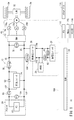
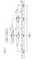
図1は、本発明の一実施形態に係る燃料電池車両10(以下「FC車両10」又は「車両10」という。)の概略全体構成図である。FC車両10は、燃料電池システム12(以下「FCシステム12」という。)と、走行モータ14(以下「モータ14」という。)と、インバータ16とを有する。
1. Explanation of overall configuration [1-1. overall structure]
FIG. 1 is a schematic overall configuration diagram of a fuel cell vehicle 10 (hereinafter referred to as “FC vehicle 10” or “vehicle 10”) according to an embodiment of the present invention. The FC vehicle 10 includes a fuel cell system 12 (hereinafter referred to as “FC
FCシステム12は、燃料電池ユニット20(以下「FCユニット20」という。)と、高電圧バッテリ22(以下「バッテリ22」ともいう。)(蓄電装置)と、昇圧コンバータ24と、昇降圧コンバータ26と、補機28と、電子制御装置30(以下「ECU30」という。)とを有する。
The
[1−2.駆動系]
本実施形態のモータ14は、3相交流ブラシレス式である。モータ14は、FCユニット20及びバッテリ22から供給される電力に基づいて駆動力を生成し、当該駆動力によりトランスミッション32を通じて車輪34を回転させる。また、モータ14は、回生を行うことで生成した電力(回生電力Preg)[W]をバッテリ22等に出力する。モータ14の各相(U相、V相、W相)の電流は、電流センサ36u、36v、36wにより検出される。或いは、3相のうち2相のみ電流を検出し、これらの電流から残りの1相の電流を検出してもよい。
[1-2. Drive system]
The
インバータ16は、3相ブリッジ型の構成を有し、直流−交流変換を行う。より具体的には、インバータ16は、直流を3相の交流に変換してモータ14に供給する一方、回生動作に伴う交流−直流変換後の直流を昇降圧コンバータ26を通じてバッテリ22等に供給する。なお、モータ14とインバータ16を併せて負荷40という。
The
[1−3.FCユニット20]
FCユニット20は、燃料電池スタック50(以下「FCスタック50」又は「FC50」という。)と、その周辺部品とを備える。FCスタック50は、例えば、固体高分子電解質膜をアノード電極とカソード電極とで両側から挟み込んで形成された燃料電池セルを積層した構造を有する。前記周辺部品には、FCスタック50のアノードに対して水素(燃料ガス)を給排するアノード系と、FCスタック50のカソードに対して酸素を含む空気(酸化剤ガス)を給排するカソード系と、FCスタック50を冷却する冷却系と、セル電圧モニタとが含まれる。後述するように、前記周辺部品の一部は、補機28にも含まれる。なお、図1に示すように、FCユニット20(FC50)とインバータ16の間において昇圧コンバータ24と並列に、逆流防止ダイオード52が配置されている。
[1-3. FC unit 20]
The
FC50の出力電圧(以下「FC電圧Vfc」という。)は、電圧センサ54により検出され、FC50の出力電流(以下「FC電流Ifc」という。)は、電流センサ56により検出され、いずれもECU30に出力される。
The output voltage of the FC 50 (hereinafter referred to as “FC voltage Vfc”) is detected by the
[1−4.高電圧バッテリ22]
バッテリ22は、複数のバッテリセルを含む蓄電装置(エネルギストレージ)であり、例えば、リチウムイオン2次電池、ニッケル水素2次電池又はキャパシタ等を利用することができる。本実施形態ではリチウムイオン2次電池を利用している。バッテリ22の出力電圧(以下「バッテリ電圧Vbat」という。)[V]は、電圧センサ60により検出され、バッテリ22の出力電流(以下「バッテリ電流Ibat」という。)[A]は、電流センサ62により検出され、それぞれECU30に出力される。ECU30は、バッテリ電圧Vbatとバッテリ電流Ibatとに基づいて、バッテリ22の残容量(SOC)[%]を算出する。
[1-4. High voltage battery 22]
The
[1−5.昇圧コンバータ24]
昇圧コンバータ24は、FC50の出力電圧(FC電圧Vfc)を昇圧してインバータ16に供給する昇圧チョッパ型の電圧変換装置(DC/DCコンバータ)である。昇圧コンバータ24は、FC50とインバータ16との間に配置される。換言すると、昇圧コンバータ24は、一方がFC50のある1次側1Sfに接続され、他方がバッテリ22と負荷40との接続点である2次側2Sに接続されている。以下では、昇圧コンバータ24を、FC50用電圧制御ユニットの意味で「FC−VCU24」とも称する。
[1-5. Boost Converter 24]
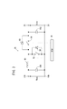
The
図2は、FC−VCU24の構成例を示す模式的回路図である。FC−VCU24は、インダクタ70、スイッチング素子72、ダイオード74及び平滑コンデンサ76を備え、ECU30を通じてスイッチング素子72がスイッチング(デューティ制御)されることでFC電圧Vfcを昇圧する。昇圧された電圧は、インバータ16の入力端電圧(以下「インバータ入力端電圧Vinv」又は「入力端電圧Vinv」という。)となる。インバータ入力端電圧Vinvは、電圧センサ78(図1)により検出される。また、FC−VCU24の出口端電流(以下「出口端電流Ifcvcu」という。)は、電流センサ80により検出される。
FIG. 2 is a schematic circuit diagram illustrating a configuration example of the FC-
スイッチング素子72がオフ状態(開状態)に維持されると、FC50からの電力(以下「FC電力Pfc」という。)は、ダイオード52を有する配線又はインダクタ70及びダイオード74を有する配線を通じて昇圧なしに供給可能となる。以下では、昇圧なしにFC電力Pfcが供給させる状態を「直結状態」といい、直結状態を実現するための動作を「直結処理」といい、直結状態を実現するための処理を「直結処理」という。
When the switching
直結状態では、FC−VCU24による昇圧が行われないため、インバータ入力端電圧Vinvは、FC電圧Vfcと等しくなる。より正確には、直結状態では、入力端電圧Vinvは、FC電圧Vfcからダイオード52、74による電圧降下分を引いた値となるが、以下では、入力端電圧VinvがFC電圧Vfcと実質的に等しいものとして説明をする。
In the direct connection state, boosting by the FC-
なお、ダイオード74は、ダイオード52と同じように、直結用且つ逆流防止用として動作するので、ダイオード52を省略してもよい。
Note that the
[1−6.昇降圧コンバータ26]
昇降圧コンバータ26は、昇降圧チョッパ型の電圧変換装置(DC/DCコンバータ)である。すなわち、昇降圧コンバータ26は、バッテリ22の出力電圧(バッテリ電圧Vbat)を昇圧してインバータ16に供給すると共に、モータ14の回生電圧(以下「回生電圧Vreg」という。)又はFC電圧Vfcとしてのインバータ入力端電圧Vinvを降圧してバッテリ22に供給することが可能である。昇降圧コンバータ26は、バッテリ22とインバータ16との間に配置される。換言すると、昇降圧コンバータ26は、一方がバッテリ22のある1次側1Sbに接続され、他方がFC50と負荷40との接続点である2次側2Sに接続されている。以下では、昇降圧コンバータ26を、バッテリ22用電圧制御ユニットの意味で「BAT−VCU26」とも称する。
[1-6. Buck-Boost Converter 26]
The step-up / down
図3は、BAT−VCU26の構成例を示す模式的回路図である。BAT−VCU26は、インダクタ90と、スイッチング素子92、94と、これらスイッチング素子92、94にそれぞれ並列に接続されるダイオード96、98と、平滑コンデンサ100、102とを備える。
FIG. 3 is a schematic circuit diagram showing a configuration example of the BAT-
昇圧時(バッテリ22を用いた力行時)には、ECU30により、スイッチング素子94がオフ状態とされ、スイッチング素子92がスイッチング(デューティ制御)されることでバッテリ電圧Vbatを昇圧する。昇圧された電圧は、インバータ入力端電圧Vinvとなる。
At the time of boosting (during power running using the battery 22), the
降圧時(回生時又はバッテリ22を用いない力行時)には、ECU30により、スイッチング素子92がオフ状態とされ、スイッチング素子94がスイッチング(デューティ制御)されることでインバータ入力端電圧Vinvをバッテリ電圧Vbatまで降圧する。
At the time of step-down (during regeneration or power running without using the battery 22), the
上記のように、インバータ入力端電圧Vinvは、電圧センサ78(図1)により検出される。また、BAT−VCU26の出口端電流(以下「出口端電流Ibatvcu」という。)は、電流センサ104により検出される。
As described above, the inverter input terminal voltage Vinv is detected by the voltage sensor 78 (FIG. 1). Further, the outlet end current of the BAT-VCU 26 (hereinafter referred to as “outlet end current Ibatvcu”) is detected by the
BAT−VCU26においても、FC−VCU24と同様の直結状態を実現することが可能であり、BAT−VCU26は、直結動作又は直結処理を行うことができる。
The BAT-
本実施形態では、ECU30によりFC−VCU24及びBAT−VCU26を制御することにより、FCユニット20からのFC電力Pfcと、バッテリ22から供給される電力(以下「バッテリ電力Pbat」という。)[W]と、モータ14からの回生電力Pregとの供給先を制御する。
In the present embodiment, the
[1−7.補機28]
補機28としては、例えば、エアポンプ、ウォータポンプ、エアコンディショナ、降圧型DC−DCコンバータ、低電圧バッテリ、アクセサリ、ラジエータファン及びECU30の少なくとも1つを含むことができる。
[1-7. Auxiliary machine 28]
As the
前記エアポンプは、FC50にエアを供給する。前記ウォータポンプは、FC50を冷却する冷媒としての水を循環させる。前記エアコンディショナは、車両10内の気温等を調整する。前記降圧型DC−DCコンバータは、昇降圧コンバータ26(BAT−VCU26)の1次側1Sbにおける電圧を降圧して前記低電圧バッテリ、前記アクセサリ、前記ラジエータファン及びECU30に供給する。前記低電圧バッテリは、低電圧機器を作動させるためのバッテリ(例えば、12Vバッテリ)である。前記アクセサリは、オーディオ機器、ナビゲーション装置等の機器を含む。前記ラジエータファンは、前記ウォータポンプにより循環させる冷媒をラジエータにおいて冷却させるためのファンである。
The air pump supplies air to the
補機28のうち前記エアポンプ、前記ウォータポンプ及び前記ラジエータファンは、FCユニット20にも含まれる。
The air pump, the water pump, and the radiator fan among the
[1−8.ECU30]
ECU30は、通信線106(図1)を介して、モータ14、インバータ16、FCユニット20、バッテリ22、昇圧コンバータ24、昇降圧コンバータ26及び補機28を制御する。当該制御に際しては、ECU30は、記憶部に記憶されたプログラムを実行する。また、ECU30は、電圧センサ54、60、78、電流センサ36u、36v、36w、56、62、80、104等の各種センサの検出値を用いる。
[1-8. ECU 30]
The
ここでの各種センサには、上記センサに加え、開度センサ110及びモータ回転数センサ112(図1)が含まれる。開度センサ110は、アクセルペダル114の開度θp[度]を検出する。回転数センサ112は、モータ14の回転数(以下「モータ回転数Nmot」又は「回転数Nmot」という。)[rpm]を検出する。ECU30は、回転数Nmotを用いてFC車両10の車速V[km/h]を検出する。さらに、ECU30には、メインスイッチ116(以下「メインSW116」という。)が接続される。メインSW116は、FCユニット20及びバッテリ22からモータ14への電力供給の可否を切り替えるものであり、ユーザにより操作可能である。
The various sensors here include an
ECU30は、マイクロコンピュータを含み、必要に応じて、A/D変換器、D/A変換器等の入出力インタフェースを有する。なお、ECU30は、1つのECUのみからなるのではなく、モータ14、FCユニット20、バッテリ22、昇圧コンバータ24、昇降圧コンバータ26及び補機28毎の複数のECUから構成することもできる。
The
ECU30は、FCスタック50の状態、バッテリ22の状態及びモータ14の状態の他、各種スイッチ及び各種センサからの入力(負荷要求)に基づき決定したFC車両10全体としてFCシステム12に要求される負荷から、FCスタック50が負担すべき負荷と、バッテリ22が負担すべき負荷と、回生電源(モータ14)が負担すべき負荷の配分(分担)を調停しながら決定し、モータ14、インバータ16、FCユニット20、バッテリ22、昇圧コンバータ24及び昇降圧コンバータ26に指令を送出する。
The
2.本実施形態の制御
次に、ECU30における制御について説明する。
2. Control of this Embodiment Next, the control in ECU30 is demonstrated.
[2−1.基本制御]
図4には、ECU30における基本的な制御のフローチャートが示されている。メインSW116がオンでない場合(S1:NO)、ECU30は起動しない。メインSW116がオンである場合(S1:YES)、ECU30が起動し、ステップS2に進む。ステップS2において、ECU30は、FCシステム12に要求される負荷(システム負荷Psys)[W]を計算する。
[2-1. Basic control]
FIG. 4 shows a flowchart of basic control in the
ステップS3において、ECU30は、FCシステム12のエネルギマネジメントを行う。ここにいうエネルギマネジメントは、FCシステム12の各部の動作制御を行う処理である。例えば、エネルギマネジメントでは、システム負荷Psysを各電力源(力行時にはバッテリ22及び/又はFC50であり、回生時にはモータ14(及び該当する場合、FC50)である。)のいずれにどのように割り振るかを設定する。また、当該割り振りに伴い、FC50の発電量(FC電力Pfc)及びFC50の周辺機器の動作、各コンバータ24、26の動作等を設定する。
In step S3, the
ステップS4において、ECU30は、ステップS3のエネルギマネジメントの演算結果に基づいて、FCスタック50の周辺機器の制御(FC発電制御)を行う。ここにいう周辺機器には、例えば、前記エアポンプ、前記ウォータポンプ及び前記ラジエータファンに加え、FCユニット20の各種の弁(循環弁、背圧弁等)が含まれる。
In step S4, the
ステップS5において、ECU30は、ステップS3のエネルギマネジメントの演算結果に基づいて、モータ14のトルク制御(モータトルク制御)を行う。ここにいうモータトルク制御は、インバータ16の制御を含む。
In step S5, the
ステップS6において、メインSW116がオフでない場合(S6:NO)、ステップS2に戻る。メインSW116がオフである場合(S6:YES)、ECU30は停止して処理を終了する。
If the
[2−2.システム負荷Psysの計算]
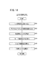
図5には、システム負荷Psysを計算するフローチャート(図4のS2の詳細)が示されている。ステップS11において、ECU30は、開度センサ110からアクセルペダル114の開度θpを読み込む。ステップS12において、ECU30は、回転数センサ112からモータ14の回転数Nmotを読み込む。
[2-2. Calculation of system load Psys]
FIG. 5 shows a flowchart for calculating the system load Psys (details of S2 in FIG. 4). In step S <b> 11, the
ステップS13において、ECU30は、開度θpと回転数Nmotに基づいてモータ14の予想消費電力Pmot_cons[W]を算出する。具体的には、図6に示すマップにおいて、開度θp毎に回転数Nmotと予想消費電力Pmot_consの関係を記憶しておく。例えば、開度θpがθp1であるとき、特性120を用いる。同様に、開度θpがθp2、θp3、θp4、θp5、θp6であるとき、それぞれ特性122、124、126、128、130を用いる。なお、開度θ1〜θ6の関係は、θp1<θp2<θp3<θp4<θp5<θp6である。そして、開度θpに基づいて回転数Nmotと予想消費電力Pmot_consとの関係を示す特性を特定した上で、回転数Nmotに応じた予想消費電力Pmot_consを特定する。
In step S13, the
ステップS14において、ECU30は、補機28から現在の動作状況を読み込む。ここでの補機28には、例えば、前記エアポンプ、前記ウォータポンプ及び前記エアコンディショナを含む高電圧系の補機や、前記低電圧バッテリ、前記アクセサリ、前記ラジエータファン及びECU30を含む低電圧系の補機が含まれる。例えば、前記エアポンプ及び前記ウォータポンプであれば、それぞれの回転数[rpm]を読み込む。前記エアコンディショナであれば、その出力設定を読み込む。
In step S <b> 14, the
ステップS15において、ECU30は、各補機28の現在の動作状況に応じて補機28の消費電力Pa[W]を算出する。ステップS16において、ECU30は、モータ14の予想消費電力Pmot_consと補機28の消費電力Paの和をFC車両10全体での予想消費電力(すなわち、システム負荷Psys)として算出する。
In step S15, the
[2−3.エネルギマネジメント]
上記のように、本実施形態におけるエネルギマネジメントでは、FCシステム12の各部の動作制御を行う。以下では、特に車両10が力行中である場合に絞って説明する。
[2-3. Energy management]
As described above, in the energy management in the present embodiment, operation control of each unit of the
(2−3−1.作動させるDC/DCコンバータの選択)
エネルギマネジメントの一環として、ECU30は、昇圧コンバータ24(FC−VCU24)及び昇降圧コンバータ26(BAT−VCU26)のいずれを作動させるかを選択する。例えば、寒冷地においてメインSW116がオンにされた直後には、FC50を暖機させるため、バッテリ22のみから電力供給する。この場合、BAT−VCU26のみを作動させる。また、車両10の加速時(特に急加速時)には、バッテリ22及びFC50の両方から電力供給する。この場合、FC−VCU24及びBAT−VCU26の両方を作動させる。さらに、車両10の巡航時には、FC50のみから電力供給する。この場合、FC−VCU24のみを作動させる。
(2-3-1. Selection of DC / DC converter to be operated)
As part of energy management, the
作動させるDC/DCコンバータの選択方法としては、例えば、特開2009−165244号公報(図14等)の方法を用いてもよい。 As a method for selecting a DC / DC converter to be operated, for example, a method disclosed in JP 2009-165244 A (FIG. 14 and the like) may be used.
(2−3−2.インバータ入力端電圧Vinvの制御)
本実施形態では、車両10の力行時には、インバータ入力端電圧Vinvを制御対象としてFC−VCU24及びBAT−VCU26の少なくとも一方を作動させる。すなわち、入力端電圧Vinvの目標値(以下「目標入力端電圧Vinv_tar」という。)を設定し、入力端電圧Vinvが目標入力端電圧Vinv_tarと等しくなるように、FC−VCU24及びBAT−VCU26を制御する。
(2-3-2. Control of inverter input terminal voltage Vinv)
In the present embodiment, when the vehicle 10 is powered, at least one of the FC-
図7は、インバータ入力端電圧Vinvを制御するフローチャートである。ステップS21において、ECU30は、モータ回転数Nmotを取得する。ここにいうモータ回転数Nmotは、実測値又は要求値のいずれであってもよい。本実施形態では、回転数センサ112からモータ回転数Nmot(実測値)を取得する。
FIG. 7 is a flowchart for controlling the inverter input terminal voltage Vinv. In step S21, the
ステップS22において、ECU30は、モータトルクTmotを取得する。ここにいうモータ回転数Nmotは、実測値(以下「検出モータトルクTmot_det」という。)又は要求値(以下「要求モータトルクTmot_req」)のいずれであってもよい。検出モータトルクTmot_detは、例えば、図示しないトルクセンサの検出値を用いることができる。また、要求モータトルクTmot_reqは、例えば、アクセルペダル114の開度θpに応じて設定される。或いは、要求モータトルクTmot_reqとして、後述する図14の処理で算出する目標トルクTtarを用いてもよい。なお、図4では、図14の処理(図4のS5)は本処理(図4のS3)よりも後に行われる。この場合、本処理では、例えば、前回の演算周期で用いた目標トルクTtarを用いることができる。
In step S22, the
ステップS23において、ECU30は、FC50の出力電圧の実測値(すなわち、FC電圧Vfc)又はその目標値を取得する。本実施形態では、電圧センサ54からFC電圧Vfcを取得する。
In step S23, the
ステップS24において、ECU30は、FC電圧Vfcに応じて目標電圧マップ150(図9参照)を変化させる。目標電圧マップ150(以下「マップ150」ともいう。)は、モータ回転数Nmot及びモータトルクTmotの組合せとインバータ入力端電圧Vinvの目標値(目標入力端電圧Vinv_tar)の関係を規定したものであり、ECU30の図示しない記憶部に記憶されている。或いは、マップ150は、図示しない通信装置を用いて外部機器(外部サーバ、光ビーコン、周辺車両等)から取得したものであってもよい。マップ150の詳細については後述する。
In step S24, the
ステップS25において、ECU30は、ステップS24で変化させたマップ150を用いて、ステップS21のモータ回転数Nmot及びステップS22のモータトルクTmotに基づいて目標入力端電圧Vinv_tarを算出する。
In step S25, the
ステップS26において、ECU30は、電圧センサ78からインバータ入力端電圧Vinv(実測値)を取得する。
In step S <b> 26, the
ステップS27において、ECU30は、インバータ入力端電圧Vinv及び目標入力端電圧Vinv_tarに基づいて昇圧コンバータ24及び昇降圧コンバータ26の少なくとも一方を制御する。
In step S27, the
具体的には、入力端電圧Vinvが目標入力端電圧Vinv_tarよりも小さい場合(Vinv<Vinv_tar)、作動させるコンバータ24、26の昇圧率(デューティ比)を増加させる。入力端電圧Vinvが目標入力端電圧Vinv_tarよりも大きい場合(Vinv>Vinv_tar)、作動させるコンバータ24、26の昇圧率(デューティ比)を減少させる。入力端電圧Vinvが目標入力端電圧Vinv_tarと等しい場合(Vinv=Vinv_tar)、作動させるコンバータ24、26の昇圧率(デューティ比)を維持する。
Specifically, when the input terminal voltage Vinv is smaller than the target input terminal voltage Vinv_tar (Vinv <Vinv_tar), the boosting rate (duty ratio) of the
(2−3−3.目標電圧マップ150)
次に、目標電圧マップ150の基本的な考え方について説明する。
(2-3-3. Target voltage map 150)
Next, the basic concept of the
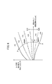
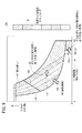
(2−3−3−1.モータ14の電力効率を考慮した参考マップ140)
図8は、モータ回転数Nmot及びモータトルクTmotの組合せと要求モータ電圧Vmot_reqとの関係を規定した参考マップ140の一例を示す。ここにいうモータ回転数Nmot及びモータトルクTmotは、実測値又は要求値のいずれであってもよい。また、要求モータ電圧Vmot_reqは、例えば、アクセルペダル114の開度θpに応じて特定されるモータ14の目標入力電圧であり、モータ14の電力効率(以下「電力効率Emot」という。)を考慮して設定される。本実施形態の要求モータ電圧Vmot_reqは、モータ14の電力効率Emotに加え、インバータ16の電力効率(以下「電力効率Einv」という。)も考慮して設定される。要求モータ電圧Vmot_reqをモータ14の目標入力電圧としてそのまま用いた場合、要求モータ電圧Vmot_reqは、目標入力端電圧Vinv_tarと同じ値となる。
(2-3-3-1.
FIG. 8 shows an example of a
上記のように、図8の参考マップ140では、モータ14及びインバータ16の電力効率Emot、Einvを考慮して、モータ回転数Nmot及びモータトルクTmotと要求モータ電圧Vmot_reqとの関係を規定している。以下では、モータ14及びインバータ16の電力効率Emot、Einvを統合して負荷40の電力効率Eloadともいう。
As described above, the
モータ14の電力効率Emot及びインバータ16の電力効率Einv(すなわち、負荷40の電力効率Eload)は、負荷40への入力電圧(ここではインバータ入力端電圧Vinv)に応じて変化する。すなわち、特開2009−165244号公報の図24A〜図24Cにも示されているように、モータ14又は負荷40の高効率領域は、入力端電圧Vinvが高くなるほど、モータ回転数Nmotが高くなる方向又はモータトルクTmotが高くなる方向に移動する傾向にある。換言すると、モータ回転数Nmotが高い場合又はモータトルクTmotが高い場合、入力端電圧Vinvが高くなる程、モータ14の電力効率Emot及びインバータ16の電力効率Einvは高くなる傾向にある。
The power efficiency Emot of the
そこで、参考マップ140では、モータ回転数Nmotが高い場合又はモータトルクTmotが高い場合、要求モータ電圧Vmot_reqを高くする。本実施形態では、参考マップ140に基づく目標電圧マップ150を用いるが、参考マップ140自体は使用しないことに留意されたい。
Therefore, in the
(2−3−3−2.FCシステム12全体の電力効率を考慮した目標電圧マップ150の概要)
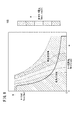
図9は、モータ回転数Nmot及びモータトルクTmotの組合せとインバータ入力端電圧Vinvの目標値(目標入力端電圧Vinv_tar)との関係を規定した目標電圧マップ150の一例を示す。マップ150は、参考マップ140に基づいて設定されるものであり、本実施形態において実際に用いられるマップである。ここにいうモータ回転数Nmot及びモータトルクTmotは、実測値又は目標値のいずれであってもよい。
(2-3-3-2. Outline of
FIG. 9 shows an example of a
図9に示すように、マップ150では、主として4つの領域(第1〜第4領域A1〜A4)を設ける。各領域A1〜A4は、FCシステム12全体としての電力効率(以下「電力効率Etotal」という。)を考慮して区分される。すなわち、FCシステム12の電力効率Etotalには、モータ14及びインバータ16の電力効率Emot、Einvに加え、昇圧コンバータ24(FC−VCU24)の電力効率(以下「電力効率Efcvcu」という。)も反映される。
As shown in FIG. 9, in the
第1領域A1は、参考マップ140と同じ特性を有する領域である。第2領域A2は、モータ14の高負荷状態において、モータ14、インバータ16及び昇圧コンバータ24(FC−VCU24)の電力効率Emot、Einv、Efcvcuを考慮して、参考マップ140よりも電圧を低くした領域である。図9の矢印152は、図9の第2領域A2の特性が、参考マップ140において第2領域A2に対応する領域の特性よりも電圧が低くなること、すなわち、モータ回転数Nmot及びモータトルクTmotが同じ場合、参考マップ140における要求モータ電圧Vmot_reqよりも目標電圧マップ150の目標入力端電圧Vinv_tarの方が低いことを示している。
The first area A1 is an area having the same characteristics as the
図9の第3領域A3は、モータ14の低負荷状態において、モータ14の電力損失Lmot及びFC−VCU24の電力損失Lfcvcuを考慮して、参考マップ140よりも電圧を低くした領域である。図9の矢印154は、図9の第3領域A3の特性が、参考マップ140において第3領域A3に対応する領域の特性よりも電圧が低くなること、すなわち、モータ回転数Nmot及びモータトルクTmotが同じ場合、参考マップ140における要求モータ電圧Vmot_reqよりも目標電圧マップ150の目標入力端電圧Vinv_tarの方が低いことを示している。
A third region A3 in FIG. 9 is a region where the voltage is lower than that of the
第4領域A4は、モータ14、インバータ16及びFC−VCU24の電力効率Emot、Einv、Efcvcuを考慮して、FC−VCU24を直結状態とした領域である。本実施形態の第4領域A4は、FC電圧Vfcに応じて可変である。図9の矢印156は、図9の第4領域A4が、FC電圧Vfcに応じて可変であることを示している。
The fourth area A4 is an area in which the FC-
第1・第2領域A1、A2は、モータ14の高負荷状態に対応し、第3・第4領域A3、A4は、モータ14の低負荷状態に対応する。ここにいう「高負荷状態」及び「低負荷状態」は、例えば、次のように定義する。すなわち、モータ14、インバータ16及びFC−VCU24の電力効率Emot、Einv、Efcvcuを総合的に考えた際(すなわち、FCシステム12の電力効率Etotalを考えた際)、FC−VCU24により昇圧を行う場合よりも、FC−VCU24を直結状態にした場合の方がFCシステム12全体の電力効率Etotalが高くなる範囲を「低負荷状態」と定義する。反対に、FC−VCU24により昇圧を行う場合よりも、FC−VCU24を直結状態にした場合の方がFCシステム12全体の電力効率Etotalが低くなる範囲を「高負荷状態」と定義する。
The first and second regions A1 and A2 correspond to the high load state of the
「高負荷状態」及び「低負荷状態」のいずれであるかは、モータ14の負荷又は出力(以下「モータ出力Pmot」という。)が、所定の閾値(負荷閾値又はモータ出力閾値)を超えるか否かで判断する。換言すると、前記負荷閾値又は前記モータ出力閾値は、高負荷状態及び低負荷状態を判定するための閾値である。モータ出力閾値の一例が、後述する第2モータ出力閾値THpmot2(図11のS31)である。モータ14の負荷又はモータ出力Pmotは、モータ回転数NmotとモータトルクTmotの積(Nmot×Tmot)として定義される。図9において、曲線158は、高負荷領域(第1・第2領域A1、A2)と、低負荷領域(第3・第4領域A3、A4)の境界線を示す。
Whether the load is high or low (whether the load or output of the motor 14 (hereinafter referred to as “motor output Pmot”) exceeds a predetermined threshold (load threshold or motor output threshold). Judge by no. In other words, the load threshold or the motor output threshold is a threshold for determining a high load state and a low load state. An example of the motor output threshold is a second motor output threshold THpmot2 (S31 in FIG. 11) described later. The load of the
なお、FC−VCU24により昇圧を行う場合と、FC−VCU24を直結状態にした場合とのFCシステム12全体の電力効率Etotalの比較は、例えば、シミュレーション値又は理論値により行うことができる。
Note that the comparison of the power efficiency Etotal of the
(2−3−3−3.昇圧コンバータ24(FC−VCU24)の電力損失)
FC50のみから電力を供給している場合、FCシステム12全体の電力効率Etotalには、モータ14、インバータ16の電力効率Emot、Einv又は電力損失(以下「電力損失Lmot、Linv」という。)に加え、FC−VCU24の電力効率Efcvcu又は電力損失(以下「電力損失Lfcvcu」という。)が影響する。以下では、FC−VCU24の電力損失Lfcvcuについて述べる。
(2-3-3-3. Power Loss of Boost Converter 24 (FC-VCU24))
When power is supplied only from the
図10は、FC−VCU24の通過電力(以下「通過電力Pfcvcu」という。)と電力損失Lfcvcuの関係をFC−VCU24の出力電圧(すなわち、インバータ入力端電圧Vinv)毎に示した図である。図10において、「Vfc」は、FC電圧Vfcであり、M1〜M4は昇圧率である(1<M1<M2<M3<M4)。図10では、FC電圧Vfcは一定であると仮定していることに留意されたい。 FIG. 10 is a diagram showing the relationship between the passing power of the FC-VCU 24 (hereinafter referred to as “passing power Pfccvcu”) and the power loss Lfcvcu for each output voltage of the FC-VCU 24 (that is, the inverter input terminal voltage Vinv). In FIG. 10, “Vfc” is the FC voltage Vfc, and M1 to M4 are step-up rates (1 <M1 <M2 <M3 <M4). Note that FIG. 10 assumes that the FC voltage Vfc is constant.
図10に示すように、通過電力Pfcvcuが等しいとすれば、FC−VCU24が直結状態にあるとき、FC−VCU24の電力損失Lfcvcuが小さく、FC−VCU24の出力電圧(インバータ入力端電圧Vinv)が高くなる程、電力損失Lfcvcuが大きくなる。
As shown in FIG. 10, if the passing power Pfcvcu is equal, when the FC-
なお、FC−VCU24が直結状態である場合、FC−VCU24が昇圧動作をしている場合と比べて極端に電力損失Lfcvcuが小さい。これは、昇圧動作をしているときには、FC−VCU24の電力損失Lfcvcuに固定分(固定損失)が発生するためである。
Note that when the FC-
(2−3−3−4.第4領域A4)
本実施形態では、FCシステム12全体の電力効率Etotalを考慮して第1〜第4領域A1〜A4(図9)を設定する。説明の都合上、以下では第4領域A4、第3領域A3、第2領域A2及び第1領域A1の順に説明する。
(2-3-3-4. Fourth region A4)
In the present embodiment, the first to fourth regions A1 to A4 (FIG. 9) are set in consideration of the power efficiency Etotal of the
第4領域A4は、モータ14が低負荷状態であり且つモータ回転数Nmotが比較的低い状態に用いる領域である。モータ14が低負荷状態であれば、FC−VCU24の通過電力Pfcvcuは低くなる。このため、本実施形態において、FCシステム12全体としての電力効率Etotalは、モータ14の電力効率EmotよりもFC−VCU24の電力効率Efcvcuの方が支配的となる。また、モータトルクTmotが比較的高い状態(高トルク状態)であっても、FC−VCU24が直結状態であれば、FC50は比較的大きな電流を出力可能であるため、高トルク状態に対応可能である。
The fourth region A4 is a region used when the
そこで、FC−VCU24の電力効率Efcvcuを中心に考えて、FC−VCU24を直結状態とする。図9においてモータ回転数Nmotの閾値(モータ回転数閾値THnmot)を設定しているのは、モータ14が低負荷であっても、モータ回転数Nmotを高く維持するため又は回転数Nmotを過度に低下させないためには、インバータ入力端電圧Vinvを高くする必要が生じるためである(図8の参考マップ140参照)。すなわち、高いモータ回転数Nmotを維持するため又は回転数Nmotを過度に低下させないために、インバータ入力端電圧Vinvを高くする場合、FC−VCU24の電力効率Efcvcuと比較してモータ14の電力効率Emotも無視できなくなるため、FC−VCU24を直結状態にはしないのである。
Therefore, the FC-
また、図7のステップS24で言及したように、本実施形態では、第4領域A4をFC電圧Vfcに応じて変化させる。この点については、図11及び図12を参照して後述する。 Further, as mentioned in step S24 of FIG. 7, in the present embodiment, the fourth region A4 is changed according to the FC voltage Vfc. This point will be described later with reference to FIGS. 11 and 12.
(2−3−3−5.第3領域A3)
第3領域A3は、モータ出力Pmotが比較的低い状態(低負荷状態)であり且つモータ回転数Nmotが比較的高い状態に用いる領域である。第4領域A4に関連して説明したように、モータ14が低負荷であっても、高いモータ回転数Nmotを維持するため又は回転数Nmotを過度に低下させないためには、インバータ入力端電圧Vinvを高くする必要が生じる(図8の参考マップ140参照)。高いモータ回転数Nmotを維持するため又は回転数Nmotを過度に低下させないために、入力端電圧Vinvを高くする場合、FC−VCU24の電力効率Efcvcuと比較してモータ14の電力効率Emotも無視できなくなる。さらに、低負荷状態且つ高回転状態の場合、モータトルクTmotは低くなる。そこで、FC−VCU24を直結状態とはせず、FC−VCU24による昇圧を行う。
(2-3-3-5. Third region A3)
The third region A3 is a region used when the motor output Pmot is in a relatively low state (low load state) and the motor rotational speed Nmot is relatively high. As described in relation to the fourth region A4, in order to maintain the high motor rotation speed Nmot or not excessively reduce the rotation speed Nmot even when the
但し、第3領域A3では、参考マップ140における特性よりもインバータ入力端電圧Vinvを低くする。これは、モータ14及びインバータ16の電力効率Emot、Einvに加え、FC−VCU24の電力効率Efcvcuを考慮したためである。
However, in the third region A3, the inverter input terminal voltage Vinv is made lower than the characteristic in the
(2−3−3−6.第2領域A2)
第2領域A2は、モータ出力Pmotが比較的高い状態(高負荷状態)であり且つモータトルクTmotが比較的低い状態(低トルク状態)に用いる領域である。上記のように、モータ14が高負荷状態であれば、FC−VCU24の通過電力Pfcvcuは大きくなり、FC−VCU24の電力効率EfcvcuがFCシステム12の電力効率Etotalに与える影響が大きくなる。
(2-3-3-6. Second region A2)
The second region A2 is a region used when the motor output Pmot is relatively high (high load state) and the motor torque Tmot is relatively low (low torque state). As described above, when the
そこで、モータ14及びインバータ16の電力効率Emot、Einvに加え、FC−VCU24の電力効率Efcvcuを考慮して、FC−VCU24の昇圧率を参考マップ140よりも低くする。これにより、FCシステム12全体としての電力効率Etotalを向上させることが可能となる。
Therefore, the boosting rate of the FC-
(2−3−3−7.第1領域A1)
第1領域A1は、モータ出力Pmotが比較的高い状態(高負荷状態)であり且つモータトルクTmotが比較的高い状態(高トルク状態)に用いる領域である。第1領域A1では、参考マップ140の特性をそのまま用いる。これは、高負荷且つ高トルク状態では、モータ14及びインバータ16の電力効率Emot、Einvが、FCシステム12の電力効率Etotalにおいて支配的となるためである。
(2-3-3-7. First region A1)
The first region A1 is a region used when the motor output Pmot is relatively high (high load state) and the motor torque Tmot is relatively high (high torque state). In the first area A1, the characteristics of the
なお、図9では、第1領域A1と第2領域A2の境界線160が右上に向かって傾斜している。これは、FCシステム12の電力効率Etotalを反映した結果である。
In FIG. 9, the
(2−3−3−8.目標電圧マップ150における各領域A1〜A4の具体的設定方法)
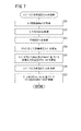
図11は、目標電圧マップ150における各領域(第1〜第4領域A1〜A4)の設定方法を示すフローチャートである。本実施形態において、図11は、ECU30が実際に実行する処理ではなく、ECU30が用いるマップ150を設定する際の基準又は指標であることに留意されたい。但し、ECU30が実行する処理として図11の内容を用いてもよい。
(2-3-3-8. Specific Setting Method for Each Area A1 to A4 in Target Voltage Map 150)
FIG. 11 is a flowchart illustrating a method for setting each region (first to fourth regions A1 to A4) in the
ステップS31において、モータ14が低負荷状態であるか否かを判断する。具体的には、モータ14の出力(モータ出力Pmot)が第1閾値(以下「第1モータ出力閾値THpmot1」又は「閾値THpmot1」という。)を上回り且つ第2閾値(以下「第2モータ出力閾値THpmot2」又は「閾値THpmot2」という。)を下回るか否かを判断する。閾値THpmot1は、モータ14が回生状態ではなく駆動状態であるか否かを判定する値(下限値)であり、例えば、0kW又はその近傍値である。また、閾値THpmot2は、モータ14が低負荷状態であるかを判定するための上限値である。
In step S31, it is determined whether or not the
図7のステップS24で述べたように、本実施形態では、FC電圧Vfcに応じてマップ150を変化させる。具体的には、FC電圧Vfcに応じて閾値THpmot2を切り替えることにより、マップ150を変化させる。
As described in step S24 of FIG. 7, in the present embodiment, the
図12は、FC電圧Vfcと第2モータ出力閾値THpmot2の関係の一例を示す図である。図12に示すように、FC電圧Vfcが閾値(以下「FC電圧閾値THvfc」という。)以下であるときは、第2モータ出力閾値THpmot2を一定とする。また、FC電圧VfcがFC電圧閾値THvfcを上回るときは、第2モータ出力閾値THpmot2を徐々に増加させる。これにより、FC電圧Vfcが比較的高い場合、第2モータ出力閾値THpmot2が徐々に大きくなる。従って、FC電圧Vfcが高くなると、第4領域A4が広くなる(図11参照)。その結果、FC電圧Vfcが高い場合、直結処理を行い易くなる。 FIG. 12 is a diagram illustrating an example of the relationship between the FC voltage Vfc and the second motor output threshold THpmot2. As shown in FIG. 12, when the FC voltage Vfc is less than or equal to a threshold value (hereinafter referred to as “FC voltage threshold value THvfc”), the second motor output threshold value THpmot2 is made constant. On the other hand, when the FC voltage Vfc exceeds the FC voltage threshold THvfc, the second motor output threshold THpmot2 is gradually increased. Thus, when the FC voltage Vfc is relatively high, the second motor output threshold THpmot2 gradually increases. Therefore, as the FC voltage Vfc increases, the fourth region A4 becomes wider (see FIG. 11). As a result, when the FC voltage Vfc is high, the direct connection process is easily performed.
なお、上記のように、図9における矢印156は、FC電圧Vfcに応じて第2モータ出力閾値THpmot2を切り替えた結果、各領域A1〜A4(特に第4領域A4)が変化する様子を示している。
As described above, the
図11のステップS31においてモータ14が低負荷状態でない場合(S31:NO)、ステップS32において、モータトルクTmotが高いか否かを判定する。具体的には、モータトルクTmotがトルク閾値THtmotを上回るか否かにより判定する。
If the
モータトルクTmotが高い場合(S32:YES)、ステップS33において、要求モータ電圧Vmot_reqをそのまま目標入力端電圧Vinv_tarに設定する(Vinv_tar←Vmot_req)。当該値は、マップ150の第1領域A1の値となる。
When the motor torque Tmot is high (S32: YES), in step S33, the required motor voltage Vmot_req is set to the target input terminal voltage Vinv_tar as it is (Vinv_tar ← Vmot_req). This value is the value of the first area A1 of the
モータトルクTmotが高くない場合(S32:NO)、ステップS34において、要求モータ電圧Vmot_reqから正の所定値αを引いた値を目標入力端電圧Vinv_tarに設定する(Vinv_tar←Vmot_req−α)。当該値は、マップ150の第2領域A2の値となる。所定値αは、モータ14及びインバータ16の電力効率Emot、Einvに加え、FC−VCU24の電力効率Efcvcuを考慮した値(すなわち、FCシステム12の電力効率Etotalを考慮した値)である。
When the motor torque Tmot is not high (S32: NO), in step S34, a value obtained by subtracting a predetermined positive value α from the required motor voltage Vmot_req is set as the target input terminal voltage Vinv_tar (Vinv_tar ← Vmot_req−α). This value is the value of the second area A2 of the
ステップS31に戻り、モータ14が低負荷状態である場合(S31:YES)、ステップS35において、モータ回転数Nmotが高いか否か(高回転状態であるか否か)を判定する。具体的には、モータ回転数Nmotが所定の閾値(回転数閾値THnmot)(図9参照)を上回るか否かを判定する。回転数閾値THnmotは、モータ回転数Nmotが高いか否かを判定するための閾値であり、高回転状態を維持するため又は回転数Nmotを過度に低下させないためのインバータ入力端電圧Vinv及びモータトルクTmotを考慮して設定される。
Returning to step S31, when the
モータ回転数Nmotが高い場合(S35:YES)、ステップS36において、要求モータ電圧Vmot_reqから正の所定値βを引いた値を目標入力端電圧Vinv_tarに設定する(Vinv_tar←Vmot_req−β)。当該値は、マップ150の第3領域A3の値となる。所定値βは、モータ14の電力損失Lmot及び昇圧コンバータ24の電力損失Lfcvcuを考慮した値である。例えば、電力損失Lmot、Lfcvcuの合計が最小値又はその近傍値となる値に設定する。或いは、所定値βは、モータ14及び昇圧コンバータ24の電力損失Lmot、Lfcvcuに加え、インバータ16の電力損失Linvを考慮した値としてもよい。例えば、電力損失Lmot、Linv、Lfcvcuの合計が最小値又はその近傍値となる値に設定する。
When the motor rotation speed Nmot is high (S35: YES), in step S36, a value obtained by subtracting a predetermined positive value β from the required motor voltage Vmot_req is set as the target input terminal voltage Vinv_tar (Vinv_tar ← Vmot_req−β). The value is the value of the third area A3 of the
モータ回転数Nmotが高くない場合(S35:NO)、ステップS37において、FC電圧Vfcを目標入力端電圧Vinv_tarに設定する(Vinv_tar←Vfc)。当該値は、マップ150の第4領域A4の値になる。また、FC電圧Vfcを目標入力端電圧Vinv_tarに設定するということは、昇圧コンバータ24を昇圧動作させないこと、すなわち、直結処理を意味する。なお、ここでは、実測値としてのFC電圧Vfcの代わりにその目標値を用いてもよい。
When the motor rotation speed Nmot is not high (S35: NO), in step S37, the FC voltage Vfc is set to the target input terminal voltage Vinv_tar (Vinv_tar ← Vfc). This value is the value of the fourth area A4 of the
以上のように、図11では、モータ14が低負荷状態であるか否か(S31)、モータ14が高トルク状態であるか否か(S32)及びモータ14が高回転状態であるか否か(S35)に基づいて第1〜第4領域A1〜A4を区分する。
As described above, in FIG. 11, whether the
或いは、上記3つの基準を判断する順番を変更することにより第1〜第4領域A1〜A4を区分してもよい。或いは、領域の数を4つとせず、2、3又は5以上の領域に区分してもよい。 Alternatively, the first to fourth regions A1 to A4 may be divided by changing the order in which the above three criteria are determined. Alternatively, the number of regions may not be four, but may be divided into two, three, or five or more regions.
(2−3−4.各種制御の例)
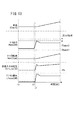
図13は、本実施形態に係る各種制御を用いた場合のタイムチャートの一例を示す。図13の時点t1〜t2の間は、車両10が相対的に低車速で巡航状態であり、モータ出力Pmot、モータ回転数Nmot、目標入力端電圧Vinv_tar及びFC−VCU24の電力損失Lfcvcuはいずれも略一定である。ここでは、FC−VCU24が直結状態(目標入力端電圧Vinv_tar=FC電圧Vfc)であり、モータ回転数Nmot及びモータトルクTmotから特定される目標入力端電圧Vinv_tarは第4領域A4に属する(図11のS37参照)。
(2-3-4. Examples of various controls)
FIG. 13 shows an example of a time chart when various controls according to the present embodiment are used. During time t1 to t2 in FIG. 13, the vehicle 10 is in a cruising state at a relatively low vehicle speed, and the motor output Pmot, the motor rotation speed Nmot, the target input terminal voltage Vinv_tar and the power loss Lfcvcu of the FC-
時点t2になると、アクセルペダル114が踏み込まれ、モータ出力Pmotが増加する。なお、時点t2〜t3の間、目標入力端電圧Vinv_tar及びFC−VCU24の電力損失Lfcvcuが一定であるのは、FC−VCU24が直結状態であるためである。
At time t2, the
時点t3になると、モータ出力Pmotが閾値THpmot2を上回る(図11のS31:YES)。これに伴い、FC−VCU24は、直結処理を終了し、昇圧動作を開始する。但し、本実施形態におけるECU30の実際の動作としては、モータ回転数Nmot及びモータトルクTmotから目標入力端電圧Vinv_tarを特定しているに過ぎず、その結果として算出される目標入力端電圧Vinv_tarが第4領域A4に属すること(図11のS37参照)に留意されたい。
At time t3, the motor output Pmot exceeds the threshold THpmot2 (S31 in FIG. 11: YES). Along with this, the FC-
また、時点t3では、モータ14は高トルク状態でないため(図11のS32:NO)、モータ回転数Nmot及びモータトルクTmotから特定される目標入力端電圧Vinv_tarは、要求モータ電圧Vmot_reqから正の所定値αを引いた値となる。すなわち、目標入力端電圧Vinv_tarは第2領域A2に属する値に設定される。
At time t3, since the
[2−4.FC発電制御]
図4のFC発電制御(S4)について説明する。上記のように、FC発電制御として、ECU30は、FCスタック50の周辺機器を制御する。具体的には、ECU30は、エネルギマネジメント(図4のS3)で算出したこれらの機器の指令値を用いてこれらの機器を制御する。
[2-4. FC power generation control]
The FC power generation control (S4) in FIG. 4 will be described. As described above, the
[2−5.モータ14のトルク制御]
図14を参照して、図4のモータトルク制御(S5)について説明する。図14には、モータトルク制御のフローチャート(図4のS5の詳細)が示されている。ステップS41において、ECU30は、回転数センサ112からモータ回転数Nmotを読み込む。ステップS42において、ECU30は、開度センサ110からアクセルペダル114の開度θpを読み込む。
[2-5. Torque control of motor 14]
The motor torque control (S5) in FIG. 4 will be described with reference to FIG. FIG. 14 shows a flowchart of motor torque control (details of S5 in FIG. 4). In step S41, the
ステップS43において、ECU30は、モータ回転数Nmotと開度θpに基づいてモータ14の仮目標トルクTtar_p[N・m]を算出する。具体的には、回転数Nmot、開度θp及び仮目標トルクTtar_pを関連付けたマップを図示しない記憶手段に記憶しておき、当該マップと、回転数Nmot及び開度θpに基づいて仮目標トルクTtar_pを算出する。
In step S43, the
ステップS44において、ECU30は、FCシステム12からモータ14に供給可能な電力の限界値(限界供給電力Ps_lim)[W]に等しいモータ14の限界出力(モータ限界出力Pm_lim)[W]を算出する。具体的には、限界供給電力Ps_lim及びモータ限界出力Pm_limは、FCスタック50からのFC電力Pfcとバッテリ22から供給可能な電力の限界値(限界出力Pbat_lim)[W]との和から補機28の消費電力Paを引いたものである(Pm_lim=Ps_lim←Pfc+Pbat_lim−Pa)。
In step S44, the
ステップS45において、ECU30は、モータ14のトルク制限値Tlim[N・m]を算出する。具体的には、モータ限界出力Pm_limを車速Vで除したものをトルク制限値Tlimとする(Tlim←Pm_lim/V)。
In step S45, the
一方、ステップS44において、ECU30は、モータ14が回生中であると判定した場合には、限界供給回生電力Ps_reglimを算出する。限界供給回生電力Ps_reglimは、バッテリ22に充電可能な電力の限界値(限界充電Pbat_chglim)とFCスタック50からのFC電力Pfcとの和から補機28の消費電力Paを引いたものである(Ps_reglim=Pbat_chglim+Pfc−Pa)。回生中である場合、ステップS45において、ECU30は、モータ14の回生トルク制限値Treglim[N・m]を算出する。具体的には、限界供給回生電力Ps_reglimを車速Vsで除したものをトルク制限値Tlimとする(Tlim←Ps_reglim/Vs)。
On the other hand, when it is determined in step S44 that the
ステップS46において、ECU30は、目標トルクTtar[N・m]を算出する。具体的には、ECU30は、仮目標トルクTtar_pに対してトルク制限値Tlimによる制限を加えたものを目標トルクTtarとする。例えば、仮目標トルクTtar_pがトルク制限値Tlim以下である場合(Ttar_p≦Tlim)、仮目標トルクTtar_pをそのまま目標トルクTtarとする(Ttar←Ttar_p)。一方、仮目標トルクTtar_pがトルク制限値Tlimを超える場合(Ttar_p>Tlim)、トルク制限値Tlimを目標トルクTtarとする(Ttar←Tlim)。
In step S46, the
そして、算出した目標トルクTtarを用いてモータ14を制御する。
Then, the
3.本実施形態の効果
以上説明したように、本実施形態によれば、モータ出力Pmot(モータ14の負荷)が閾値THpmot2(負荷閾値)を下回るとき(すなわち、モータ14が低負荷状態であるとき)(図11のS31:YES)、FC−VCU24(DC/DCコンバータ)の昇圧動作を停止させて、FC50からモータ14に電力を供給させる、すなわち、直結処理を行う(図11のS37及び図9の第4領域A4参照)。従って、低負荷時におけるFC−VCU24の電力損失Lfcvcu(スイッチング損失)を低減することが可能となる。
3. Effects of the Present Embodiment As described above, according to the present embodiment, when the motor output Pmot (load of the motor 14) is lower than the threshold value THpmot2 (load threshold value) (that is, when the
また、本実施形態によれば、FC電圧Vfcに応じて閾値THpmot2(負荷閾値)を変化させる。従って、モータ14の負荷に応じて直結処理を用いる構成において、FC電圧Vfcに応じて直結処理の実行タイミング又は停止タイミングを切り替えることが可能となる。その結果、直結処理を効率的に利用することが可能となる。
Further, according to the present embodiment, the threshold value THpmot2 (load threshold value) is changed according to the FC voltage Vfc. Therefore, in the configuration using the direct connection process according to the load of the
本実施形態において、ECU30(制御装置)は、回転数閾値THnmot(図9)を設定し、モータ出力Pmot(モータ14の負荷)が閾値THpmot2(負荷閾値)を下回り(図11のS31:YES)且つモータ回転数Nmotが回転数閾値THnmotを上回る場合(S35:YES)、FC−VCU24での電力損失Lfcvcuとモータ14での電力損失Lmotの合算値としての電力損失Ltotalを算出し、電力損失Ltotalが低くなるようにFC−VCU24の昇圧率を算出する(図11のS36及び図9の第3領域A3参照)。
In the present embodiment, the ECU 30 (control device) sets the rotation speed threshold THnmot (FIG. 9), and the motor output Pmot (load of the motor 14) falls below the threshold THpmot2 (load threshold) (S31 of FIG. 11: YES). When the motor rotation speed Nmot exceeds the rotation speed threshold THnmot (S35: YES), a power loss Ltotal is calculated as a sum of the power loss Lfcvcu at the FC-
上記によれば、モータ出力Pmotが閾値THpmot2を下回り且つモータ回転数Nmotがモータ回転数閾値THnmotを上回る場合(すなわち、モータ14が低負荷状態及び高回転状態である場合)、FC−VCU24での電力損失Lfcvcuとモータ14での電力損失Lmotの合算値としてのFCシステム12全体の電力損失Ltotalが低くなるようにFC−VCU24の昇圧率を算出する。従って、モータ14が低負荷状態且つ高回転状態(例えば、下り坂を走行中の場合)におけるFCシステム12(電力システム)全体としての電力損失Ltotalを低減することが可能となる。
According to the above, when the motor output Pmot is lower than the threshold value THpmot2 and the motor rotational speed Nmot is higher than the motor rotational speed threshold value THnmot (that is, when the
本実施形態では、高負荷且つ高トルクの状態の場合、要求モータトルクTmot_req及びモータ回転数Nmotに基づく要求モータ電圧Vmot_reqを目標入力端電圧Vinv_tarとしてそのまま用いる(図9の領域A1)。従って、モータ14を高効率で動作させることが可能となる。
In the present embodiment, in the case of a high load and high torque state, the required motor voltage Vmot_req based on the required motor torque Tmot_req and the motor rotation speed Nmot is used as it is as the target input terminal voltage Vinv_tar (area A1 in FIG. 9). Therefore, the
また、高負荷且つ低トルクの状態の場合、要求モータ電圧Vmot_reqより小さい値(Vmot_req−α)を目標入力端電圧Vinv_tarとして用いる(図9の領域A2)。従って、低トルク状態の場合、FC−VCU24の昇圧率を下げて、FC−VCU24の電力損失Lfcvcu(スイッチング損失)の低減を図ることが可能となる。その結果、モータ14及びFC−VCU24の両方を考慮した際のエネルギ効率を向上することが可能となる。
In the case of a high load and low torque state, a value (Vmot_req−α) smaller than the required motor voltage Vmot_req is used as the target input terminal voltage Vinv_tar (region A2 in FIG. 9). Therefore, in the low torque state, it is possible to reduce the boosting rate of the FC-
本実施形態によれば、FC車両10はFCシステム12を有し、モータ14が走行用モータである。これにより、電力効率に優れたFC車両10を提供することが可能となる。
According to this embodiment, the FC vehicle 10 has the
4.変形例
なお、本発明は、上記実施形態に限らず、この明細書の記載内容に基づき、種々の構成を採り得ることはもちろんである。例えば、以下の構成を採用することができる。
4). Modifications It should be noted that the present invention is not limited to the above-described embodiment, and it is needless to say that various configurations can be adopted based on the description in this specification. For example, the following configuration can be adopted.
[4−1.搭載対象]
上記実施形態では、FCシステム12をFC車両10に搭載したが、これに限らず、例えば、FC電圧Vfcを昇圧してモータ14に供給するFC−VCU24(DC/DCコンバータ)を利用する観点からすれば、FCシステム12を別の対象に搭載してもよい。例えば、FCシステム12を船舶や航空機等の移動体に用いることもできる。或いは、FCシステム12を、ロボット、製造装置、家庭用電力システム又は家電製品に適用してもよい。
[4-1. Installation target]
In the above embodiment, the
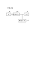
[4−2.FCシステム12の構成]
上記実施形態では、FC50と高電圧バッテリ22を並列に配置し、FC50の手前に昇圧コンバータ24を配置し、バッテリ22の手前に昇降圧コンバータ26を配置する構成としたが、これに限らない。例えば、バッテリ22の手前に配置するDC/DCコンバータを昇降圧式ではなく、昇圧式としてもよい。或いは、図15に示すように、FC50とバッテリ22を並列に配置し、昇圧式、降圧式又は昇降圧式のDC/DCコンバータ170をFC50の手前に配置する構成であってもよい。或いは、FC50とDC/DCコンバータ170のみを用い、バッテリ22及び昇降圧コンバータ26を用いない構成も可能である。
[4-2. Configuration of FC system 12]
In the above embodiment, the
上記実施形態では、モータ14を交流式としたが、例えば、FC電圧Vfcを昇圧してモータ14に供給するFC−VCU24(DC/DCコンバータ)を利用する観点からすれば、モータ14は、直流式とすることも可能である。この場合、インバータ16を省略することも可能である。
In the above embodiment, the
上記実施形態では、モータ14をFC車両10の走行用又は駆動用としたが、例えば、FC電圧Vfcを昇圧してモータ14に供給するFC−VCU24(DC/DCコンバータ)を利用する観点からすれば、これに限らない。例えば、モータ14を車載機器(例えば、電動パワーステアリング、エアコンプレッサ、エアコンディショナ)用に用いてもよい。
In the above embodiment, the
上記実施形態では、FC−VCU24の構成例として図2の回路を示し、BAT−VCU26の構成例として図3の回路を示した。しかしながら、DC/DCコンバータとしての機能の観点からすれば、FC−VCU24及びBAT−VCU26の構成はこれに限らない。例えば、図2の回路の代わりに、特開2009−165244号公報の図2に示される構成の昇圧コンバータ(及びそのための制御)を用いることも可能である。
In the above embodiment, the circuit of FIG. 2 is shown as a configuration example of the FC-
[4−3.FCシステム12の制御]
上記実施形態では、目標電圧マップ150の領域を主として4つに分けたが、その他の特徴(例えば、第4領域A4をFC電圧Vfcに応じて変化させる点)に着目すれば、これに限らない。例えば、第1〜第4領域A1〜A4のうちいずれか2つ又は3つのみを用いてもよい。例えば、第1・第2・第4領域A1、A2、A4のみの組合せ、第1・第3・第4領域A1、A3、A4のみの組合せ、第1・第4領域A1、A4のみの組合せ又は第2・第4領域A2、A4のみの組合せも可能である。或いは、第1〜第4領域A1〜A4に加え、その他の領域を設定することも可能である。
[4-3. Control of FC system 12]
In the above-described embodiment, the
上記実施形態では、目標電圧マップ150の第4領域A4をFC電圧Vfcに応じて変化させた(図7のS24)。しかしながら、その他の特徴(例えば、第1〜第4領域A1〜A4に区分する点)に着目すれば、第4領域A4は固定としてもよい。
In the above embodiment, the fourth region A4 of the
10…燃料電池車両 12…燃料電池システム(電力システム)
14…モータ 16…インバータ
24…昇圧コンバータ(DC/DCコンバータ)
26…昇降圧コンバータ 30…ECU(制御装置)
50…燃料電池スタック(燃料電池) 170…DC/DCコンバータ
Emot…モータの電力効率 Lfcvcu…昇圧コンバータの電力損失
Lmot…モータの電力損失 Nmot…モータ回転数
Pmot…モータ出力(モータの負荷) THnmot…モータ回転数閾値
THpmot2…第2モータ出力閾値(負荷閾値)
THtmot…トルク閾値 Tmot_req…要求モータトルク
Vfc…FC電圧(燃料電池の出力電圧)
Vinv_tar…目標入力端電圧(DC/DCコンバータの目標出力電圧)
Vmot_req…要求モータ電圧
10 ...
14 ...
26 ... Buck-
50: Fuel cell stack (fuel cell) 170: DC / DC converter Emot: Motor power efficiency Lfcvcu: Boost converter power loss Lmot: Motor power loss Nmot: Motor rotation speed Pmot: Motor output (motor load) THnmot ... Motor rotation speed threshold THpmot2 ... second motor output threshold (load threshold)
THtmot ... Torque threshold value Tmot_req ... Required motor torque Vfc ... FC voltage (fuel cell output voltage)
Vinv_tar Target input terminal voltage (DC / DC converter target output voltage)
Vmot_req: Requested motor voltage
Claims (3)
モータと、
前記燃料電池と前記モータの間に配置され、前記燃料電池からの直流電力を交流電力に変換して前記モータに供給するインバータと、
前記燃料電池と前記インバータの間に配置され、前記燃料電池の出力電圧を昇圧するDC/DCコンバータと、
前記DC/DCコンバータを制御する制御装置と
を備える電力システムであって、
前記制御装置は、
モータ回転数の閾値である回転数閾値を設定し、
前記モータの負荷が負荷閾値を下回り且つ前記モータ回転数が前記回転数閾値を下回る場合、前記DC/DCコンバータの昇圧動作を停止させて、前記燃料電池から前記モータに電力を供給させ、
前記モータの負荷が前記負荷閾値を下回り且つ前記モータ回転数が前記回転数閾値を上回る場合、前記DC/DCコンバータでの電力損失と前記モータでの電力損失の合算値を低下させることを基準として前記DC/DCコンバータの昇圧率を算出し、
前記モータの負荷が前記負荷閾値を上回るとき、前記DC/DCコンバータに昇圧動作を実行させ、
前記燃料電池の出力電圧に応じて前記負荷閾値を変化させる
ことを特徴とする電力システム。 A fuel cell;
A motor,
An inverter that is disposed between the fuel cell and the motor, converts direct current power from the fuel cell into alternating current power, and supplies the alternating current power to the motor;
A DC / DC converter disposed between the fuel cell and the inverter and boosting an output voltage of the fuel cell;
A control device for controlling the DC / DC converter;
A power system comprising:
The controller is
Set the rotation speed threshold that is the motor rotation speed threshold,
When the load of the motor falls below a load threshold value and the motor rotation speed falls below the rotation speed threshold value, the DC / DC converter is stopped from boosting operation to supply power from the fuel cell to the motor,
When the load of the motor falls below the load threshold and the motor rotation speed exceeds the rotation speed threshold, the sum of the power loss at the DC / DC converter and the power loss at the motor is reduced as a reference. Calculating the step-up rate of the DC / DC converter ;
When the load of the motor exceeds the load threshold, the DC / DC converter is caused to perform a boost operation,
An electric power system, wherein the load threshold is changed according to an output voltage of the fuel cell .
モータと、
前記燃料電池と前記モータの間に配置され、前記燃料電池からの直流電力を交流電力に変換して前記モータに供給するインバータと、
前記燃料電池と前記インバータの間に配置され、前記燃料電池の出力電圧を昇圧するDC/DCコンバータと、
前記DC/DCコンバータを制御する制御装置と
を備える電力システムであって、
前記モータの電力効率を考慮して要求モータトルク及びモータ回転数に基づいて特定される前記モータへの目標入力電圧を要求モータ電圧と定義するとき、
前記制御装置は、
前記モータの負荷が負荷閾値を下回るとき、前記DC/DCコンバータの昇圧動作を停止させて、前記燃料電池から前記モータに電力を供給させ、
前記モータの負荷が前記負荷閾値を上回り且つ前記要求モータトルクがトルク閾値を上回る場合、前記DC/DCコンバータの目標出力電圧として前記要求モータ電圧を設定して、前記DC/DCコンバータに昇圧動作を実行させ、
前記モータの負荷が前記負荷閾値を上回り且つ前記要求モータトルクが前記トルク閾値を下回る場合、前記DC/DCコンバータの目標出力電圧として前記要求モータ電圧より小さい値を設定して、前記DC/DCコンバータに昇圧動作を実行させ、
前記燃料電池の出力電圧に応じて前記負荷閾値を変化させる
ことを特徴とする電力システム。 A fuel cell;
A motor,
An inverter that is disposed between the fuel cell and the motor, converts direct current power from the fuel cell into alternating current power, and supplies the alternating current power to the motor;
A DC / DC converter disposed between the fuel cell and the inverter and boosting an output voltage of the fuel cell;
A control device for controlling the DC / DC converter;
A power system comprising:
When the target input voltage to the motor that is identified to define the required motor voltage based on the required motor torque及beauty motors rotation speed in consideration of the power efficiency of the motor,
The controller is
When the load of the motor falls below a load threshold, the boost operation of the DC / DC converter is stopped and power is supplied from the fuel cell to the motor.
When the load of the motor exceeds the load threshold and the required motor torque exceeds the torque threshold, the required motor voltage is set as a target output voltage of the DC / DC converter, and the DC / DC converter is boosted. Let it run
When the load of the motor exceeds the load threshold and the required motor torque is lower than the torque threshold, a value smaller than the required motor voltage is set as a target output voltage of the DC / DC converter, and the DC / DC converter To perform the boost operation,
An electric power system, wherein the load threshold is changed according to an output voltage of the fuel cell .
前記モータが走行用モータである
ことを特徴とする燃料電池車両。 The power system according to claim 1 or 2 ,
The fuel cell vehicle, wherein the motor is a traveling motor.
Priority Applications (1)
| Application Number | Priority Date | Filing Date | Title |
|---|---|---|---|
| JP2013037516A JP6104635B2 (en) | 2013-02-27 | 2013-02-27 | Electric power system and fuel cell vehicle |
Applications Claiming Priority (1)
| Application Number | Priority Date | Filing Date | Title |
|---|---|---|---|
| JP2013037516A JP6104635B2 (en) | 2013-02-27 | 2013-02-27 | Electric power system and fuel cell vehicle |
Publications (2)
| Publication Number | Publication Date |
|---|---|
| JP2014166103A JP2014166103A (en) | 2014-09-08 |
| JP6104635B2 true JP6104635B2 (en) | 2017-03-29 |
Family
ID=51616227
Family Applications (1)
| Application Number | Title | Priority Date | Filing Date |
|---|---|---|---|
| JP2013037516A Active JP6104635B2 (en) | 2013-02-27 | 2013-02-27 | Electric power system and fuel cell vehicle |
Country Status (1)
| Country | Link |
|---|---|
| JP (1) | JP6104635B2 (en) |
Families Citing this family (6)
| Publication number | Priority date | Publication date | Assignee | Title |
|---|---|---|---|---|
| JP6310888B2 (en) | 2015-09-04 | 2018-04-11 | 本田技研工業株式会社 | Control method for fuel cell system and fuel cell vehicle |
| JP6228620B2 (en) | 2016-03-09 | 2017-11-08 | 本田技研工業株式会社 | Power supply system |
| KR101878036B1 (en) * | 2016-06-07 | 2018-07-16 | 현대자동차주식회사 | Control method and system for converter of vehicle |
| JP6724585B2 (en) * | 2016-06-17 | 2020-07-15 | トヨタ自動車株式会社 | Fuel cell system |
| JP7251913B2 (en) * | 2017-06-28 | 2023-04-04 | トヨタ自動車株式会社 | Machine design method |
| JP2024061945A (en) * | 2022-10-24 | 2024-05-09 | 三菱電機株式会社 | Power Conversion Equipment |
Family Cites Families (5)
| Publication number | Priority date | Publication date | Assignee | Title |
|---|---|---|---|---|
| JP4624272B2 (en) * | 2006-02-03 | 2011-02-02 | 本田技研工業株式会社 | Fuel cell vehicle control method and fuel cell vehicle |
| JP5326228B2 (en) * | 2006-09-04 | 2013-10-30 | トヨタ自動車株式会社 | Fuel cell system |
| JP4844556B2 (en) * | 2007-12-28 | 2011-12-28 | トヨタ自動車株式会社 | Power supply system |
| JP5143665B2 (en) * | 2008-08-11 | 2013-02-13 | 本田技研工業株式会社 | Electric power system and fuel cell vehicle |
| US8853989B2 (en) * | 2009-07-09 | 2014-10-07 | Toyota Jidosha Kabushiki Kaisha | Fuel cell system and motor driving method |
-
2013
- 2013-02-27 JP JP2013037516A patent/JP6104635B2/en active Active
Also Published As
| Publication number | Publication date |
|---|---|
| JP2014166103A (en) | 2014-09-08 |
Similar Documents
| Publication | Publication Date | Title |
|---|---|---|
| US8600599B2 (en) | Fuel cell vehicle | |
| JP6228620B2 (en) | Power supply system | |
| JP6104635B2 (en) | Electric power system and fuel cell vehicle | |
| CN108454419B (en) | Control device for battery system and battery system | |
| JP2009225522A (en) | Hybrid dc power supply system, fuel cell vehicle, and method of protecting electricity storage device | |
| JP2017011940A (en) | Fuel cell vehicle control method and fuel cell vehicle | |
| JP2009165244A (en) | Power supply system | |
| JP2020202605A (en) | Power supply system | |
| JP2009153344A (en) | Hybrid DC power supply system and fuel cell vehicle | |
| WO2016009476A1 (en) | Power system | |
| JP2009153342A (en) | DC / DC converter device, vehicle, fuel cell system, and driving method of DC / DC converter device | |
| JP6186315B2 (en) | Power system | |
| US10431836B2 (en) | Power supply system | |
| JP2017011883A (en) | Fuel cell automobile | |
| JP5631826B2 (en) | Fuel cell system | |
| JP5651531B2 (en) | Fuel cell vehicle | |
| JP6174553B2 (en) | Control method for fuel cell system and fuel cell vehicle | |
| JP6104637B2 (en) | Dual power load drive system and fuel cell vehicle | |
| JP2017091882A (en) | Power adjusting system | |
| JP2010124689A (en) | Fuel cell vehicle | |
| JP5763483B2 (en) | Fuel cell vehicle | |
| JP6063298B2 (en) | Electric power system and fuel cell vehicle | |
| JP6054918B2 (en) | Dual power load drive fuel cell system and fuel cell vehicle | |
| JP2009159798A (en) | DC / DC converter, DC / DC converter device, vehicle, fuel cell system, and DC / DC converter driving method | |
| JP5736282B2 (en) | Fuel cell vehicle |
Legal Events
| Date | Code | Title | Description |
|---|---|---|---|
| A621 | Written request for application examination |
Free format text: JAPANESE INTERMEDIATE CODE: A621 Effective date: 20151127 |
|
| A977 | Report on retrieval |
Free format text: JAPANESE INTERMEDIATE CODE: A971007 Effective date: 20160622 |
|
| A131 | Notification of reasons for refusal |
Free format text: JAPANESE INTERMEDIATE CODE: A131 Effective date: 20160705 |
|
| A521 | Written amendment |
Free format text: JAPANESE INTERMEDIATE CODE: A523 Effective date: 20160905 |
|
| TRDD | Decision of grant or rejection written | ||
| A01 | Written decision to grant a patent or to grant a registration (utility model) |
Free format text: JAPANESE INTERMEDIATE CODE: A01 Effective date: 20170214 |
|
| A61 | First payment of annual fees (during grant procedure) |
Free format text: JAPANESE INTERMEDIATE CODE: A61 Effective date: 20170301 |
|
| R150 | Certificate of patent or registration of utility model |
Ref document number: 6104635 Country of ref document: JP Free format text: JAPANESE INTERMEDIATE CODE: R150 |