JP4608564B2 - Abnormality diagnosis method for low-speed rotating machinery - Google Patents
Abnormality diagnosis method for low-speed rotating machinery Download PDFInfo
- Publication number
- JP4608564B2 JP4608564B2 JP2008087417A JP2008087417A JP4608564B2 JP 4608564 B2 JP4608564 B2 JP 4608564B2 JP 2008087417 A JP2008087417 A JP 2008087417A JP 2008087417 A JP2008087417 A JP 2008087417A JP 4608564 B2 JP4608564 B2 JP 4608564B2
- Authority
- JP
- Japan
- Prior art keywords
- low
- rotating machine
- speed rotating
- signal
- abnormality
- Prior art date
- Legal status (The legal status is an assumption and is not a legal conclusion. Google has not performed a legal analysis and makes no representation as to the accuracy of the status listed.)
- Active
Links
Images
Landscapes
- Testing Of Devices, Machine Parts, Or Other Structures Thereof (AREA)
- Measurement Of Mechanical Vibrations Or Ultrasonic Waves (AREA)
Description
本発明は、低速回転駆動される低速回転機械のアンバランス、ミスアライメント、及び軸亀裂などの構造系異常を診断する複合センシングによる低速回転機械の異常診断方法に関する。 The present invention relates to an abnormality diagnosis method for a low-speed rotating machine by composite sensing for diagnosing structural system abnormalities such as unbalance, misalignment, and axial cracks of a low-speed rotating machine driven at a low speed.
従来、低速回転機械の異常診断方法としては、以下に示す方法が開示されている。
例えば、特許文献1には、軸受が発生するアコースティックエミッションをAE信号として検出し、このAE信号を基準値と比較して、AE信号が基準値を超えている時間を算出し、この持続時間が基準値を超えたときに軸受に損傷などの異常が発生したと診断する方法が記載されている。
また、特許文献2には、図7に示すように、回転機械を支える転がり軸受部の振動を加速度振動センサーで検出し、その振動信号を複数のバンドパスフィルターに個別に通過させ、これらフィルター出力を包絡線回路で包絡線処理すると共に、加速度センサーで検出する加速度信号を二回積分して振動変位に変換し、この振動変位と包絡線回路の出力を比較して、その相関関係から異常の有無と、異常の原因及び種別を診断する方法が記載されている。
そして、特許文献3には、回転機械の振動を振動加速度センサーで検出し、該振動検出信号をバンドパスフィルター処理して、診断対象の異常状態を表す固有帯域成分の波高率を算出し、算出した波高率の更に波高率を算出し、算出した波高率の波高率を予め設定した閾値と比較して、当該閾値を超えるピークを生じたときに異常であると診断する方法が記載されている。
Conventionally, the following method has been disclosed as an abnormality diagnosis method for a low-speed rotating machine.
For example, in
Further, in
In
しかしながら、前記従来の方法は、低速回転機械の一例である軸受の異常診断だけに適用されている。
また、特許文献1の方法は、軸受が発生するアコースティックエミッションをAE信号として検出しているが、AEセンサー自体が高価であり、例えば、連続鋳造機のローラエプロンのように、センサーの取付箇所が多い場合に費用が増加して経済的でない。しかも、診断の実施には、高い専門知識が必要であるという課題があった。
また、特許文献2、3の方法は、回転機械の振動を振動加速度センサーで検出し、その振動検出信号に基づいて異常診断を行うようにしているので、診断装置全体のコストが安価である。しかし、前述した連続鋳造機のローラエプロンのように、加振力の弱い低速回転軸受では、振動検出信号が微弱であるため、ノイズと異常に基づく有効信号成分との判別が困難であり、正確な異常診断を行うことが難しいという課題があった。
更に、回転機械の振動を振動加速度センサーで検出し、1回又は2回積分して振動速度と振動変位へ変換して低速回転機械の構造系異常を診断しているので、振動加速度センサーの仕様により検出可能な振動周波数域が制限される(振動加速度センサーの仕様:一般的に3Hz以上)。また、検出した振動加速度の電気信号を電気回路で2回積分すると、更に低周波域の信号成分がカットされ、異常に基づく有効信号成分が失われ、異常診断を正確に行うことが難しいという課題があった。
However, the conventional method is applied only to an abnormality diagnosis of a bearing which is an example of a low-speed rotating machine.
Further, in the method of
In the methods of
Furthermore, vibration of the rotating machine is detected by a vibration acceleration sensor, and it is integrated once or twice and converted into vibration speed and vibration displacement to diagnose structural abnormalities of the low-speed rotating machine. The vibration frequency range that can be detected is limited by (acceleration acceleration sensor specification: generally 3 Hz or more). In addition, if the detected electrical signal of vibration acceleration is integrated twice by the electric circuit, the signal component in the lower frequency range is further cut, the effective signal component based on the abnormality is lost, and it is difficult to accurately perform the abnormality diagnosis. was there.
本発明はかかる事情に鑑みてなされたもので、AEセンサーのように高価なセンサーを使用することなく、市販の汎用かつ安価なひずみゲージと変位計を使用し、しかも複雑な信号処理手段と判断方法を用いることなく、低速回転機械の異常診断を精度よく実施できる低速回転機械の異常診断方法を提供することを目的とする。 The present invention has been made in view of such circumstances, and uses a commercially available general-purpose and inexpensive strain gauge and displacement meter without using an expensive sensor such as an AE sensor, and is determined to be a complicated signal processing means. An object of the present invention is to provide an abnormality diagnosis method for a low-speed rotating machine that can accurately perform abnormality diagnosis for a low-speed rotating machine without using the method.
前記目的に沿う本発明に係る低速回転機械の異常診断方法は、診断対象となる低速回転機械の非回転部の動的ひずみをひずみゲージにより検出し、前記低速回転機械の回転部又は前記非回転部の動的変位を変位計により検出する検出工程と、
前記動的ひずみと前記動的変位から得られる各電気信号をフィルター処理し、前記低速回転機械の異常状態を表す周波数の固有帯域成分をそれぞれ抽出する成分抽出工程と、
前記各固有帯域成分をそれぞれ異なる複数の周波数に分解し、その周波数ごとに得られる前記各電気信号の信号レベルA、Bを、前記低速回転機械の正常状態の信号レベルと比較して、該低速回転機械の異常を診断する診断工程とを有する。
The abnormality diagnosis method for a low-speed rotating machine according to the present invention in accordance with the above object is to detect a dynamic strain of a non-rotating part of a low-speed rotating machine to be diagnosed with a strain gauge, and to rotate the rotating part or the non-rotating part of the low-speed rotating machine. Detection step of detecting the dynamic displacement of the part by a displacement meter;
A component extraction step of filtering each electrical signal obtained from the dynamic strain and the dynamic displacement and extracting a natural band component of a frequency representing an abnormal state of the low-speed rotating machine;
Each natural band component is decomposed into a plurality of different frequencies, and the signal levels A and B of the electric signals obtained for the respective frequencies are compared with the signal levels in the normal state of the low-speed rotating machine. A diagnostic process for diagnosing abnormalities in the rotating machine.
本発明に係る低速回転機械の異常診断方法において、前記検出工程では、更に、前記低速回転機械の非回転部の動的振動を振動加速度センサーにより検出し、前記成分抽出工程により、前記動的振動から得られる電気信号をフィルター処理して周波数の帯域別に信号を検出し、前記診断工程により、該周波数の帯域別に抽出した信号の信号レベルCを、前記低速回転機械の正常状態の信号レベルと比較することが好ましい。 In the abnormality diagnosis method for a low-speed rotating machine according to the present invention, in the detecting step, a dynamic vibration of a non-rotating portion of the low-speed rotating machine is further detected by a vibration acceleration sensor, and the dynamic vibration is detected by the component extracting step. The electric signal obtained from the filter is filtered to detect the signal for each frequency band, and the signal level C of the signal extracted for each frequency band is compared with the signal level of the normal state of the low-speed rotating machine by the diagnosis step. It is preferable to do.
本発明に係る低速回転機械の異常診断方法において、前記診断工程で得られる前記信号レベルA、Bにより、前記低速回転機械の構造系に関する異常の種類を特定することが好ましい。
本発明に係る低速回転機械の異常診断方法において、前記変位計に非接触型のレーザー変位センサーを使用することが好ましい。
In the abnormality diagnosis method for a low-speed rotating machine according to the present invention, it is preferable that the type of abnormality relating to the structural system of the low-speed rotating machine is specified by the signal levels A and B obtained in the diagnosis step.
In the abnormality diagnosis method for a low-speed rotating machine according to the present invention, it is preferable to use a non-contact type laser displacement sensor for the displacement meter.
請求項1〜4記載の低速回転機械の異常診断方法は、ひずみゲージにより得られる動的ひずみの電気信号と、変位計により得られる動的変位の電気信号が、低周波帯域成分の検出感度に優れているので、検出工程、成分抽出工程、及び診断工程を順次行うことで、周波数の信号成分の強さによる低速回転機械の構造系の異常の有無や異常の原因を、精度よく診断できる。なお、ひずみゲージと変位計を使用するので、高価な測定機器を使用する必要がなく、しかも検出工程、成分抽出工程、及び診断工程を行うので、特殊なデータ処理方法を使用しないため、動的振動のみで検出し診断することが難しい低速回転機械の構造系の異常、例えばアンバランスや軸折れ、ミスアライメントなどを、経済的で簡単に精度よく診断できる。
The abnormality diagnosis method for a low-speed rotating machine according to any one of
特に、請求項2記載の低速回転機械の異常診断方法は、更に、振動加速度センサーにより得られる動的振動の電気信号を検出することで、従来行っていた低速回転機械の異常診断も実施できる。
請求項3記載の低速回転機械の異常診断方法は、診断工程で得られる信号レベルA、Bにより、低速回転機械の構造に関する異常の種類を特定できるので、その後のメンテナンス作業が容易になる。
In particular, the abnormality diagnosis method for a low-speed rotating machine according to the second aspect of the present invention can also perform a conventional abnormality diagnosis for a low-speed rotating machine by detecting an electric signal of dynamic vibration obtained by a vibration acceleration sensor.
In the abnormality diagnosis method for a low-speed rotating machine according to the third aspect, the type of abnormality related to the structure of the low-speed rotating machine can be specified based on the signal levels A and B obtained in the diagnosis step, so that the subsequent maintenance work becomes easy.
請求項4記載の低速回転機械の異常診断方法は、変位計に非接触型のレーザー変位センサーを使用するので、例えば、従来からよく使用されている渦電流型の変位計と比較して、測定対象物の範囲が広く、分解能が高く、更に測定範囲を広くでき、低速回転機械の回転部の動的変位を、更に精度よく測定できる。
The abnormality diagnosis method for a low-speed rotating machine according to
続いて、添付した図面を参照しつつ、本発明を具体化した実施の形態につき説明し、本発明の理解に供する。
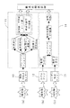
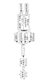
図1に示すように、本発明の一実施の形態に係る低速回転機械の異常診断方法は、診断対象となる撹拌機(低速回転機械の一例)の構造に関する異常を検出するため、検出工程、成分抽出工程、及び診断工程を順次行う方法である。なお、図1に示す(a)は、市販の振動加速度センサー10と低速回転機械の診断に対応できる振動計測診断器11による診断の流れである。また、(b)は、汎用のひずみゲージ12による診断の流れである。そして、(c)は、市販の非接触型のレーザー変位センサー(変位計の一例)13による診断の流れである。また、図1中の14は、データ処理ソフトである。以下、撹拌機の撹拌軸を回転部、撹拌軸を支持する転がり軸受のケーシング部(軸受箱)を非回転部として説明する。なお、撹拌軸の回転数は、300rpm以下、更には180rpm以下(ここでは、20〜50rpm程度)である。
Next, embodiments of the present invention will be described with reference to the accompanying drawings for understanding of the present invention.
As shown in FIG. 1, the abnormality diagnosis method for a low-speed rotating machine according to an embodiment of the present invention detects an abnormality related to the structure of a stirrer (an example of a low-speed rotating machine) to be diagnosed. In this method, a component extraction step and a diagnosis step are sequentially performed. In addition, (a) shown in FIG. 1 is the flow of diagnosis by the vibration measurement
まず、検出工程について説明する。
撹拌機の振動を検出する振動加速度センサー10を、撹拌機の撹拌軸を支持する転がり軸受のケーシング部に取り付ける。これにより、転がり軸受の振動加速度に応じた振幅(動的振動)の電気信号を、振動検出信号として出力できる。
また、外力によるケーシング部の変形を検出するひずみゲージ12を、上記した転がり軸受のケーシング部に貼り付ける。なお、ひずみゲージ12を貼り付ける場所は、転がり軸受の回転負荷により応力を一番大きく受ける場所(例えば、過去の経験から得られた場所)を選択する。これにより、応力に応じた動的ひずみの電気信号を、ひずみ検出信号として出力できる。
そして、撹拌機の撹拌軸の回転中に発生する変位を検出するレーザー変位センサー13を、撹拌軸の変位を検出できる位置(ケーシング部の変位を検出できる位置でもよい)に配置する。なお、レーザー変位センサー13による変位検出箇所は、撹拌軸の回転負荷により応力を一番大きく受ける箇所(例えば、過去の経験から得られた箇所)を選択する。これにより、撹拌軸の回転中に発生する変位に応じた動的変位の電気信号を、変位検出信号として出力できる。
First, the detection process will be described.
A
Moreover, the
And the
次に、成分抽出工程について説明する。
振動加速度センサー10から出力された振動検出信号は、従来技術と同様に、まずアンプにより増幅した後、バンドパスフィルターでフィルター処理し、周波数の帯域別に検出信号を得る。具体的には、高周波域(10〜40kHz)信号から加速度Hiの信号、中低周波域(3Hz〜10kHz)信号から加速度Mdの信号、低周波域(3〜20Hz)信号を1回積分した速度Loの信号、同様に、低周波域(5〜20Hz)の信号を2回積分した変位Dispの信号を、それぞれ取得する。
また、ひずみゲージ12から出力されたひずみ検出信号と、レーザー変位センサー13から出力された変位検出信号を、それぞれバンドパスフィルターでフィルター処理する。このとき、通過帯域の周波数は、撹拌軸の回転周波数の10〜20倍である例えば0Hzを超え20Hz以下に選定されているので、撹拌機の異常状態を表す周波数の固有帯域成分を抽出できる。
このひずみ検出信号の処理と変位検出信号の処理を行う成分抽出工程は、従来公知のデータ処理方法により行われる。
なお、バンドパスフィルターとは、低域周波数遮断のハイパスフィルターと、高域周波数遮断のローパスフィルターを組み合わせた従来公知のものである。
Next, the component extraction process will be described.
The vibration detection signal output from the
Further, the strain detection signal output from the
The component extraction process for processing the strain detection signal and the displacement detection signal is performed by a conventionally known data processing method.
The band-pass filter is a conventionally known filter that combines a high-pass filter with low-frequency cutoff and a low-pass filter with high-frequency cutoff.
続いて、診断工程について説明する。
振動加速度センサー10から検出した各帯域の検出信号、即ち加速度検出信号、速度信号、及び変位信号を、それぞれFFT変換してスペクトル(信号レベルC)を算出し、撹拌機の正常状態のスペクトル(信号レベル)と比較して、撹拌機の異常診断を行う。なお、上記した検出信号から、更に、実効値、平均値、及びピーク値を算出し、撹拌機の異常診断を行ってもよい。
ここで、FFT変換とは、高速フーリエ変換(Fast Fourier Transform)の略称であって、信号を周波数領域に変換する方法であり、周波数成分や位相を観察するのに用いる従来公知の方法である(以下同様)。
なお、振動加速度センサー10から出力された振動検出信号の処理を行う成分抽出工程と診断工程は、診断計測診断器11により行う。
Next, the diagnosis process will be described.
The detection signal of each band detected from the
Here, the FFT transform is an abbreviation for Fast Fourier Transform, which is a method of transforming a signal into the frequency domain, and is a conventionally known method used for observing frequency components and phases ( The same applies below).
The component extraction process and the diagnostic process for processing the vibration detection signal output from the
また、ひずみゲージ12で検出され、バンドパスフィルターで処理されたひずみ検出信号は、それぞれ異なる複数の周波数に分解され、FFT変換されるので、0Hzを超え20Hz以下(更には、10Hz以下)のスペクトル(周波数ごとに得られる信号レベルA)を表す。
これにより、例えば、アンバランス(撹拌翼のバランスのずれ)、ミスアライメント(撹拌機の設置時における撹拌軸の位置調整ミス)、及び軸折れ(撹拌機の使用に伴う撹拌軸の損傷)のいずれか1又は2以上の種類の構造に関する異常、即ち構造系異常があった場合、回転周波数のひずみ(応力)成分が大きくなるため、回転周波数frのひずみ成分Frが他の周波数のひずみ成分より際立つことから、異常を確認できる。
In addition, the strain detection signal detected by the
As a result, for example, any of imbalance (stirring blade misalignment), misalignment (stirring shaft misalignment when the stirrer is installed), and shaft breakage (stirring shaft damage due to use of the stirrer) If there is an abnormality related to one or more types of structures, that is, a structural system abnormality, the strain (stress) component of the rotational frequency increases, so the strain component Fr of the rotational frequency fr stands out from the strain components of other frequencies. Therefore, the abnormality can be confirmed.
そして、回転周波数frのひずみ成分Frの値ε(fr)と、10倍の回転周波数までのすべての成分Σε(fi)の実効値の比、即ち、回転周波数の信号成分に対する波高率を求め、その値が予め設定した閾値を超えているか否かを比較し判定して、異常の有無を判断する。ここで、予め設定した閾値は、撹拌機の正常状態の信号レベルから得られる値である。
更に、各方向から検出したひずみ信号のスペクトルの特徴(例えば、信号レベルAの周波数とそのひずみ強度)を観察することで、異常の原因と部位(異常の種類)を特定できる。
Then, the ratio of the value ε (fr) of the distortion component Fr of the rotational frequency fr to the effective value of all the components Σε (fi) up to 10 times the rotational frequency, that is, the crest factor for the signal component of the rotational frequency is obtained. Whether or not there is an abnormality is determined by comparing whether or not the value exceeds a preset threshold value. Here, the preset threshold value is a value obtained from the signal level in the normal state of the stirrer.
Further, by observing the characteristics of the spectrum of the strain signal detected from each direction (for example, the frequency of the signal level A and the strain intensity thereof), the cause and part of the abnormality (kind of abnormality) can be specified.
また、レーザー変位センサー13で検出され、バンドパスフィルターで処理された変位検出信号は、それぞれ異なる複数の周波数に分解され、FFT変換されるので、0Hzを超え20Hz以下(更には、10Hz以下)のスペクトル(周波数ごとに得られる信号レベルB)を表す。
これにより、例えば、アンバランス、ミスアライメント、及び軸折れのいずれか1又は2以上の構造系異常があった場合、回転周波数の変位成分が高くなり、その回転周波数frの変位成分Drを、異常によりノイズから際立たせることができる。
Further, the displacement detection signal detected by the
Thereby, for example, when there is one or more structural system abnormalities of imbalance, misalignment, and shaft breakage, the displacement component of the rotational frequency becomes high, and the displacement component Dr of the rotational frequency fr becomes abnormal. Can stand out from the noise.
そして、回転周波数frの変位成分Drの値D(fr)と,10倍の回転周波数までのすべての成分ΣD(fi)の実行値の比、即ち、回転周波数の信号成分に対する波高率を求め、その値が予め設定した閾値を超えているか否かを比較し判定して、異常の有無を判断する。ここで、予め設定した閾値は、撹拌機の正常状態の信号レベルから得られる値である。
更に、各方向から検出した変位信号のスペクトルの特徴(例えば、信号レベルBの周波数とその軸振れ強度)を観察することで、異常の原因と部位(異常の種類)を特定できる。
Then, the ratio of the value D (fr) of the displacement component Dr of the rotational frequency fr to the effective value of all the components ΣD (fi) up to 10 times the rotational frequency, that is, the crest factor for the signal component of the rotational frequency is obtained. Whether or not there is an abnormality is determined by comparing whether or not the value exceeds a preset threshold value. Here, the preset threshold value is a value obtained from the signal level in the normal state of the stirrer.
Furthermore, by observing the characteristics of the spectrum of the displacement signal detected from each direction (for example, the frequency of the signal level B and its axial runout intensity), the cause and part of the abnormality (type of abnormality) can be specified.
なお、上記した診断工程での撹拌機の異常の診断は、動的ひずみと動的変位から得られる各電気信号を組み合わせて行うことが好ましいが、得られた電気信号のいずれか一方のみを使用して行ってもよい。
以上に示したように、振動加速度センサー10、ひずみゲージ12、及びレーザー変位センサー13から得られた各信号レベルの周波数とその振幅の大きさの特徴を、撹拌機の正常状態の同じ信号レベルの周波数とその振幅の大きさの特徴と比較することで、撹拌機の異常の有無を診断すると共に、異常の原因と種別を正確に診断できる。
なお、撹拌機の診断に際しては、簡易診断と精密診断のいずれか一方又は双方を行う。ここで、簡易診断とは、信号から算出される実行値、平均値、及びピーク値が、正常状態の撹拌機の値より大きいか否かを判定する診断であり、精密診断とは、信号レベルの周波数及びその振幅の大きさ検討し、異常箇所の特定を行う診断である。
It should be noted that the diagnosis of the stirrer abnormality in the above-described diagnosis process is preferably performed by combining each electric signal obtained from dynamic strain and dynamic displacement, but only one of the obtained electric signals is used. You may do it.
As described above, the characteristics of the frequency and amplitude of each signal level obtained from the
In the diagnosis of the stirrer, either simple diagnosis or precise diagnosis or both are performed. Here, the simple diagnosis is a diagnosis for determining whether the execution value, average value, and peak value calculated from the signal are larger than the value of the stirrer in a normal state, and the precise diagnosis is a signal level. This is a diagnosis that examines the frequency and amplitude of the signal and identifies the abnormal part.
次に、本発明の作用効果を確認するために行った実施例について説明する。
ここでは、低速回転機械である撹拌機を使用して、その診断を行った結果について説明する。なお、撹拌機の仕様は、モータ:縦置き型、モータ定格:0.75kW(1780rpm)、撹拌軸の回転数:0を超え108rpm以下、撹拌翼の枚数:2枚、タンクの容積:約3075リットル、貯水量:429リットル、である。このモータの回転数は、インバータにより制御される。また、動力は、モータから減速機を経て、撹拌軸へ伝達される。そして、撹拌機の診断対象部位は、減速機以降の低速回転の撹拌軸部とする。
以下、アンバランス状態は、撹拌翼の1枚におもりを付けて診断した。
Next, examples carried out for confirming the effects of the present invention will be described.
Here, the result of having performed the diagnosis using the stirrer which is a low-speed rotating machine is demonstrated. The specifications of the stirrer are as follows: motor: vertical type, motor rating: 0.75 kW (1780 rpm), rotation speed of the stirring shaft: over 0 and 108 rpm, number of stirring blades: 2, tank volume: about 3075 Liter, water storage capacity: 429 liters. The rotation speed of this motor is controlled by an inverter. The power is transmitted from the motor to the stirring shaft via the speed reducer. And the diagnostic object part of a stirrer is made into the stirring shaft part of the low speed rotation after a reduction gear.
Hereinafter, the unbalanced state was diagnosed by attaching a weight to one of the stirring blades.
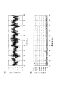
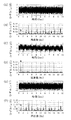
まず、撹拌機の非回転部である軸受箱(ケーシングの下方)にひずみゲージを貼り付け、撹拌機の撹拌軸の回転数を20rpm(fr=0.33Hz)にした場合に検出した軸受箱のひずみ検出信号の結果について、図2(A)、(B)、図3(A)、(B)を参照しながら説明する。なお、図2(A)、(B)は、撹拌機が正常状態の場合の結果であり、図3(A)、(B)は、アンバランス状態の場合の結果である。また、図2(A)、図3(A)、は、それぞれひずみ検出信号の時間波形であり、図2(B)、図3(B)は、それぞれひずみ検出信号をFFT変換したスペクトルである。 First, a strain gauge is attached to the bearing box (below the casing), which is a non-rotating part of the stirrer, and the bearing box detected when the rotation speed of the stirring shaft of the stirrer is 20 rpm (fr = 0.33 Hz). The result of the strain detection signal will be described with reference to FIGS. 2 (A), 2 (B), 3 (A), and 3 (B). 2A and 2B show the results when the stirrer is in a normal state, and FIGS. 3A and 3B show the results when the stirrer is in an unbalanced state. 2A and 3A are time waveforms of strain detection signals, respectively, and FIGS. 2B and 3B are spectra obtained by FFT transforming the strain detection signals, respectively. .
撹拌機が正常状態を示す図2(B)では、撹拌翼の通過周波数(図2(A)中の2fr)とその高調波成分は現れていたが、回転周波数の成分が全く確認されなかった。これは、撹拌機の運転特性に一致している(アンバランス状態とミスアライメント状態ではない)ことを意味している。
一方、撹拌機がアンバランス状態を示す図3(B)では、目立ってはいないが、撹拌翼の通過周波数(図3(B)中の2fr)のほかに、回転周波数(図3(B)中のfr)のピークも現れていた。
In FIG. 2B where the stirrer is in a normal state, the passing frequency of the stirring blade (2 fr in FIG. 2A) and its harmonic components appeared, but no component of the rotational frequency was confirmed. . This means that it matches the operating characteristics of the stirrer (not the unbalanced state and the misaligned state).
On the other hand, in FIG. 3 (B) where the stirrer is in an unbalanced state, although not conspicuous, in addition to the passing frequency of the stirring blade (2fr in FIG. 3 (B)), the rotation frequency (FIG. 3 (B) The fr) peak in the middle also appeared.
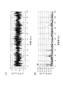
次に、撹拌機の撹拌軸の回転数を50rpm(fr=0.83Hz)にした場合に検出した軸受箱のひずみ検出信号の結果について、図4(A)〜(D)を参照しながら説明する。なお、図4(A)、(B)は、撹拌機が正常状態の場合の結果であり、図4(C)、(D)は、アンバランス状態の場合の結果である。また、図4(A)、(C)、は、それぞれひずみ検出信号の時間波形であり、図4(B)、(D)は、それぞれひずみ検出信号をFFT変換したスペクトルである。
撹拌軸の回転数を50rpmにした場合も、前記した20rpmの場合と同様、撹拌機が正常状態を示す図4(B)では、回転周波数の成分が全く確認されなかったが、撹拌機がアンバランス状態を示す図4(D)では、回転周波数(図4(D)中のfr)のピークが顕著に現れていた。
Next, the result of the bearing box strain detection signal detected when the rotation speed of the stirring shaft of the stirrer is 50 rpm (fr = 0.83 Hz) will be described with reference to FIGS. To do. 4A and 4B show the results when the stirrer is in a normal state, and FIGS. 4C and 4D show the results when the stirrer is in an unbalanced state. 4A and 4C are time waveforms of strain detection signals, respectively, and FIGS. 4B and 4D are spectra obtained by FFT transforming the strain detection signals, respectively.
Even when the rotation speed of the stirring shaft was 50 rpm, as in the case of 20 rpm described above, in FIG. 4B where the stirrer is in a normal state, the rotational frequency component was not confirmed at all. In FIG. 4D showing the balance state, the peak of the rotation frequency (fr in FIG. 4D) appeared prominently.
以上の結果から、ひずみゲージで検出されたひずみ検出信号を用いて、そのスペクトルから回転周波数の成分の変化と強さにより、撹拌機のアンバランス状態の診断と識別が可能であることを確認できた。
なお、撹拌軸の動的変位を、軸受箱に固定したレーザー変位センサーで計測したが、この場合、計測データは、軸受箱に対する撹拌軸の動的変位となるため、アンバランス状態の診断には使用できないことも確認された。
From the above results, it can be confirmed that the strain detection signal detected by the strain gauge can be used to diagnose and identify the unbalanced state of the stirrer based on the change and strength of the rotational frequency component from the spectrum. It was.
The dynamic displacement of the agitation shaft was measured with a laser displacement sensor fixed to the bearing housing.In this case, the measurement data is the dynamic displacement of the agitation shaft relative to the bearing housing. It was also confirmed that it could not be used.
続いて、低速回転機械である実験用回転機シミュレータ(以下、単にシミュレータという)を使用して、その異常を検出した結果について説明する。なお、シミュレータの仕様は、モータ定格が0.75kW(1780rpm)である。このモータの回転数は、インバータにより制御される。また、動力は、モータからベルトを経て、カップリングで接続された回転軸とロータへ伝達される。そして、シミュレータの診断対象部位は、カップリング、ロータ、回転軸、及び軸受箱である。
以下、アンバランス状態を、ロータの一箇所に107gのおもりを付けることで設定し、ミスアライメント状態を、反駆動側(従動側)の軸受箱の位置を水平方向に微調整し、カップリングを中心に回転軸と駆動側の角度を0.5度ずらすことにより設定して診断した。
Next, the result of detecting the abnormality using an experimental rotating machine simulator (hereinafter simply referred to as a simulator) that is a low-speed rotating machine will be described. The simulator has a motor rating of 0.75 kW (1780 rpm). The rotation speed of this motor is controlled by an inverter. The power is transmitted from the motor via the belt to the rotating shaft and the rotor connected by the coupling. And the diagnostic object part of a simulator is a coupling, a rotor, a rotating shaft, and a bearing box.
Hereinafter, the unbalanced state is set by attaching a weight of 107 g to one part of the rotor, the misaligned state is finely adjusted in the horizontal direction with the position of the bearing box on the non-driving side (driven side), and the coupling is adjusted. The diagnosis was made by setting the rotation axis and the drive side angle at the center by shifting by 0.5 degrees.
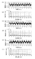
まず、シミュレータの回転部である回転軸を59rpm(fr=0.98Hz)に調整した場合に、回転軸の反駆動側をレーザー変位センサーで検出した変位検出信号の結果について、図5(A)〜(F)を参照しながら説明する。なお、図5(A)、(B)は、シミュレータが正常状態の場合の結果であり、図5(C)、(D)は、アンバランス状態の場合の結果であり、図5(E)、(F)は、ミスアライメント状態の場合の結果である。また、図5(A)、(C)、(E)は、それぞれ変位検出信号の時間波形であり、図5(B)、(D)、(F)は、それぞれ変位検出信号をFFT変換したスペクトルである。 First, FIG. 5A shows the result of the displacement detection signal obtained by detecting the counter-drive side of the rotating shaft with the laser displacement sensor when the rotating shaft, which is the rotating portion of the simulator, is adjusted to 59 rpm (fr = 0.98 Hz). This will be described with reference to (F). 5A and 5B show the results when the simulator is in a normal state, and FIGS. 5C and 5D show the results when the simulator is in an unbalanced state. FIG. , (F) are the results in the misalignment state. 5A, 5C, and 5E are time waveforms of displacement detection signals, respectively, and FIGS. 5B, 5D, and 5F are FFT-transformed displacement detection signals, respectively. It is a spectrum.
シミュレータが正常状態を示す図5(B)では、回転周波数の成分(図5(B)中のfr)とその2倍の成分が、同程度に強く現れていた。
一方、シミュレータがアンバランス状態を示す図5(D)、及びミスアライメント状態を示す図5(F)では、回転周波数の成分(図5(D)、(F)中のfr)のみが最も強く現れており、また図5(C)、(E)に示す時間波形についても、回転周波数の周期性が強く現れていた。
In FIG. 5B in which the simulator is in a normal state, the rotational frequency component (fr in FIG. 5B) and its double component appear as strong as the same.
On the other hand, only the rotational frequency component (fr in FIGS. 5D and 5F) is strongest in FIG. 5D in which the simulator shows an unbalanced state and FIG. 5F in which the misaligned state is shown. In addition, with respect to the time waveforms shown in FIGS. 5C and 5E, the periodicity of the rotation frequency was also strong.
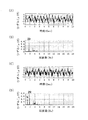
次に、シミュレータの非回転部である軸受箱の側面にひずみゲージを貼り付け、回転軸の回転数を59rpmにした場合に検出した軸受箱のひずみ検出信号の結果について、図6(A)〜(F)を参照しながら説明する。なお、図6(A)、(B)は、シミュレータが正常状態の場合の結果であり、図6(C)、(D)は、アンバランス状態の場合の結果であり、図6(E)、(F)は、ミスアライメント状態の場合の結果である。また、図6(A)、(C)、(E)は、それぞれひずみ検出信号の時間波形であり、図6(B)、(D)、(F)は、それぞれひずみ検出信号をFFT変換したスペクトルである。 Next, with respect to the result of the bearing box strain detection signal detected when a strain gauge is attached to the side surface of the bearing box, which is a non-rotating part of the simulator, and the rotational speed of the rotating shaft is 59 rpm, FIG. This will be described with reference to (F). 6A and 6B show the results when the simulator is in a normal state, and FIGS. 6C and 6D show the results when the simulator is in an unbalanced state. FIG. , (F) are the results in the misalignment state. 6 (A), (C), and (E) are time waveforms of strain detection signals, respectively, and FIGS. 6 (B), (D), and (F) are FFT-transformed strain detection signals, respectively. It is a spectrum.
シミュレータが正常状態を示す図6(B)では、回転周波数の成分(図6(B)中のfr)のピークが現れていなかった。
一方、シミュレータがアンバランス状態を示す図6(D)では、正常状態を示す図6(B)と比較して、回転周波数の成分(図6(D)中のfr)のピークが、主成分として目立って現れていた。また、ミスアライメント状態を示す図6(F)では、回転周波数の成分(図6(F)中のfr)のピークが、明らかに現れていた。
以上の結果は、アンバランス状態とミスアライメント状態の発生時の力学特性と合致しており、異常の診断が可能であることが確認された。
In FIG. 6B where the simulator is in a normal state, the peak of the rotational frequency component (fr in FIG. 6B) did not appear.
On the other hand, in FIG. 6D in which the simulator shows an unbalanced state, the peak of the rotation frequency component (fr in FIG. 6D) is the main component compared to FIG. 6B which shows the normal state. As it appeared prominently. Further, in FIG. 6F showing the misalignment state, the peak of the rotation frequency component (fr in FIG. 6F) clearly appeared.
The above results were consistent with the mechanical characteristics at the time of occurrence of the unbalanced state and the misaligned state, and it was confirmed that an abnormality could be diagnosed.
従って、低速回転機械のアンバランス状態とミスアライメント状態を診断する場合、回転数がおよそ180rpm以下の低速回転機械に対して、振動検出信号よりも、ひずみ検出信号と変位検出信号を用いて診断するのが有効であることを確認できた。更に、回転数が180rpm以上300rpm以下の低速回転機械に対しては、振動検出信号も有効ではあるが、ひずみ検出信号と変位検出信号を併用することで、より確実に状態の識別診断ができることを確認できた。 Therefore, when diagnosing the unbalanced state and the misalignment state of the low-speed rotating machine, the low-speed rotating machine whose rotation speed is approximately 180 rpm or less is diagnosed using the strain detection signal and the displacement detection signal rather than the vibration detection signal. Was confirmed to be effective. Furthermore, vibration detection signals are also effective for low-speed rotating machines with a rotational speed of 180 rpm or more and 300 rpm or less, but by using a strain detection signal and a displacement detection signal together, it is possible to more reliably identify and diagnose the state. It could be confirmed.
以上、本発明を、実施の形態を参照して説明してきたが、本発明は何ら上記した実施の形態に記載の構成に限定されるものではなく、特許請求の範囲に記載されている事項の範囲内で考えられるその他の実施の形態や変形例も含むものである。例えば、前記したそれぞれの実施の形態や変形例の一部又は全部を組合せて本発明の低速回転機械の異常診断方法を構成する場合も本発明の権利範囲に含まれる。
また、前記実施の形態においては、低速回転機械として撹拌機の異常を診断した場合について説明したが、これに限定されるものではなく、他の低速回転機械、例えば、連続鋳造機の異常を診断することもできる。
そして、前記実施の形態においては、振動加速度センサーを使用した場合について説明したが、回転数が非常に低く機械の回転にかかる荷重が大きい低速回転機械の異常を診断するには、振動加速度センサーを使用することなく、ひずみゲージとレーザー変位センサーの2つを使用して、異常の有無の診断を行ってもよい。
As described above, the present invention has been described with reference to the embodiment. However, the present invention is not limited to the configuration described in the above embodiment, and the matters described in the scope of claims. Other embodiments and modifications conceivable within the scope are also included. For example, the case where the abnormality diagnosis method for a low-speed rotating machine of the present invention is configured by combining some or all of the above-described embodiments and modifications is also included in the scope of the right of the present invention.
In the above embodiment, the case where the abnormality of the stirrer is diagnosed as the low-speed rotating machine has been described. However, the present invention is not limited to this, and an abnormality of another low-speed rotating machine, for example, a continuous casting machine is diagnosed. You can also
In the above embodiment, the case where the vibration acceleration sensor is used has been described. However, in order to diagnose an abnormality in a low-speed rotating machine having a very low rotational speed and a large load on the rotation of the machine, the vibration acceleration sensor is used. Without using it, the presence or absence of abnormality may be diagnosed using two strain gauges and a laser displacement sensor.
10:振動加速度センサー、11:振動計測診断器、12:ひずみゲージ、13:レーザー変位センサー(変位計)、14:データ処理ソフト 10: vibration acceleration sensor, 11: vibration measurement diagnostic device, 12: strain gauge, 13: laser displacement sensor (displacement meter), 14: data processing software
Claims (4)
前記動的ひずみと前記動的変位から得られる各電気信号をフィルター処理し、前記低速回転機械の異常状態を表す周波数の固有帯域成分をそれぞれ抽出する成分抽出工程と、
前記各固有帯域成分をそれぞれ異なる複数の周波数に分解し、その周波数ごとに得られる前記各電気信号の信号レベルA、Bを、前記低速回転機械の正常状態の信号レベルと比較して、該低速回転機械の異常を診断する診断工程とを有することを特徴とする低速回転機械の異常診断方法。 Detecting the dynamic strain of the non-rotating part of the low-speed rotating machine to be diagnosed with a strain gauge, and detecting the dynamic displacement of the rotating part of the low-speed rotating machine or the non-rotating part with a displacement meter;
A component extraction step of filtering each electrical signal obtained from the dynamic strain and the dynamic displacement and extracting a natural band component of a frequency representing an abnormal state of the low-speed rotating machine;
Each natural band component is decomposed into a plurality of different frequencies, and the signal levels A and B of the electric signals obtained for the respective frequencies are compared with the signal levels in the normal state of the low-speed rotating machine. And a diagnostic process for diagnosing abnormality of the rotating machine.
Priority Applications (1)
| Application Number | Priority Date | Filing Date | Title |
|---|---|---|---|
| JP2008087417A JP4608564B2 (en) | 2008-03-28 | 2008-03-28 | Abnormality diagnosis method for low-speed rotating machinery |
Applications Claiming Priority (1)
| Application Number | Priority Date | Filing Date | Title |
|---|---|---|---|
| JP2008087417A JP4608564B2 (en) | 2008-03-28 | 2008-03-28 | Abnormality diagnosis method for low-speed rotating machinery |
Publications (2)
| Publication Number | Publication Date |
|---|---|
| JP2009243908A JP2009243908A (en) | 2009-10-22 |
| JP4608564B2 true JP4608564B2 (en) | 2011-01-12 |
Family
ID=41305998
Family Applications (1)
| Application Number | Title | Priority Date | Filing Date |
|---|---|---|---|
| JP2008087417A Active JP4608564B2 (en) | 2008-03-28 | 2008-03-28 | Abnormality diagnosis method for low-speed rotating machinery |
Country Status (1)
| Country | Link |
|---|---|
| JP (1) | JP4608564B2 (en) |
Cited By (2)
| Publication number | Priority date | Publication date | Assignee | Title |
|---|---|---|---|---|
| JP7515645B1 (en) | 2023-02-27 | 2024-07-12 | Ntn株式会社 | Bearing condition monitoring system |
| KR20240117218A (en) * | 2023-01-25 | 2024-08-01 | (주)이포즌 | Apparatus and method for detecting machine parts vibration anomalies using multi columns autoencoder |
Families Citing this family (8)
| Publication number | Priority date | Publication date | Assignee | Title |
|---|---|---|---|---|
| US20150247778A1 (en) * | 2012-05-02 | 2015-09-03 | Siemens Aktiengesellschaft | Method for monitoring damage to a shaft |
| KR101663820B1 (en) * | 2014-12-26 | 2016-10-10 | 주식회사 아이티매직 | Method and apparatus of machine diagnosis using sound signal |
| CN106950069A (en) * | 2017-02-08 | 2017-07-14 | 河南中烟工业有限责任公司 | A kind of mechanical Fault Monitoring of HV method and device of packaging facilities |
| CN110926810A (en) * | 2019-11-11 | 2020-03-27 | 山东科技大学 | Ultrasonic radial bearing friction torque and high-speed running stability test device |
| JP7075466B1 (en) | 2020-11-17 | 2022-05-25 | 株式会社酉島製作所 | Abnormality diagnosis device and abnormality diagnosis method for vibrating machines |
| CN114104224B (en) * | 2021-11-15 | 2023-05-16 | 中国船舶集团有限公司第七一一研究所 | Device management method, device, electronic device and computer readable storage medium |
| CN117160336A (en) * | 2023-11-02 | 2023-12-05 | 南通凯赛生化工程设备有限公司 | Rotating speed control method and system of material mixer |
| CN119939438B (en) * | 2025-04-10 | 2025-07-22 | 福建威而特旋压科技有限公司 | A method for automatically detecting abnormality of a high-speed rotating transmission device |
Family Cites Families (6)
| Publication number | Priority date | Publication date | Assignee | Title |
|---|---|---|---|---|
| JPS6435238A (en) * | 1987-07-30 | 1989-02-06 | Anritsu Corp | Abnormality diagnosing apparatus for mechanical equipment |
| JPH0663938B2 (en) * | 1990-03-19 | 1994-08-22 | 新日本製鐵株式会社 | Misalignment status diagnosis method |
| JP3566002B2 (en) * | 1996-09-26 | 2004-09-15 | 光洋精工株式会社 | Diagnosis method of rolling bearing and rolling bearing device |
| JP3449194B2 (en) * | 1997-01-28 | 2003-09-22 | 松下電工株式会社 | Method and apparatus for diagnosing abnormalities in rotating equipment |
| JP2003177059A (en) * | 2001-12-12 | 2003-06-27 | Toshiba Corp | Vibration measuring method and vibration measuring device |
| JP2005345277A (en) * | 2004-06-03 | 2005-12-15 | Nsk Ltd | Monitoring device and monitoring method |
-
2008
- 2008-03-28 JP JP2008087417A patent/JP4608564B2/en active Active
Cited By (5)
| Publication number | Priority date | Publication date | Assignee | Title |
|---|---|---|---|---|
| KR20240117218A (en) * | 2023-01-25 | 2024-08-01 | (주)이포즌 | Apparatus and method for detecting machine parts vibration anomalies using multi columns autoencoder |
| KR102803594B1 (en) * | 2023-01-25 | 2025-05-08 | (주)이포즌 | Apparatus and method for detecting machine parts vibration anomalies using multi columns autoencoder |
| JP7515645B1 (en) | 2023-02-27 | 2024-07-12 | Ntn株式会社 | Bearing condition monitoring system |
| WO2024181292A1 (en) * | 2023-02-27 | 2024-09-06 | Ntn株式会社 | Bearing condition monitoring system |
| JP2024121320A (en) * | 2023-02-27 | 2024-09-06 | Ntn株式会社 | Bearing condition monitoring system |
Also Published As
| Publication number | Publication date |
|---|---|
| JP2009243908A (en) | 2009-10-22 |
Similar Documents
| Publication | Publication Date | Title |
|---|---|---|
| JP4608564B2 (en) | Abnormality diagnosis method for low-speed rotating machinery | |
| Singh et al. | Motor current signature analysis for bearing fault detection in mechanical systems | |
| JP5565120B2 (en) | High-frequency electromagnetic vibration component removal method and high-frequency electromagnetic vibration component removal device, rolling bearing diagnosis method and bearing diagnosis device for a rotating machine | |
| CA2687785C (en) | Parameter independent detection of rotating machinery faults | |
| JP5958932B2 (en) | Dynamic equipment condition monitoring system, method and program | |
| CN203432784U (en) | State monitoring device used for rotary mechanical components | |
| CN110044610B (en) | Gear fault diagnosis method | |
| WO2008117765A1 (en) | Abnormality diagnostic method and device of extremely low speed rotary machine | |
| JP2001304954A (en) | Failure diagnosis method and device | |
| JP6450575B2 (en) | Inverter noise elimination method and diagnostic method for equipment including inverter | |
| CN105452835A (en) | Bearing-device vibration analysis method, bearing-device vibration analysis device, and rolling-bearing status-monitoring device | |
| JP2013224853A (en) | Method of diagnosing anomalies in low speed rotational bearing of elevator | |
| JP2017122635A (en) | Abnormality diagnosis equipment for wind power generation facilities | |
| JP3875981B2 (en) | Anomaly diagnosis method and apparatus for rolling bearing | |
| JP3827896B2 (en) | Rolling bearing diagnostic device | |
| Gu et al. | Detection of faults in gearboxes using acoustic emission signal | |
| Segla et al. | Bearing fault diagnosis with an improved high frequency resonance technique | |
| JPH10281076A (en) | Pump station fault diagnosis method and pump station fault diagnosis device | |
| Blodt et al. | Mechanical fault detection in induction motor drives through stator current monitoring-theory and application examples | |
| JP6714844B2 (en) | Abnormality diagnosis method | |
| Tan et al. | An experimental study of cavitation detection in a centrifugal pump using envelope analysis | |
| Shan et al. | A novel experimental research on vibration characteristics of the running high-speed motorized spindles | |
| JP6869156B2 (en) | Status monitoring device and status monitoring method | |
| Alabied et al. | Empirical mode decomposition of motor current signatures for centrifugal pump diagnostics | |
| JP7394031B2 (en) | Abnormality detection device and abnormality detection method for rolling bearings |
Legal Events
| Date | Code | Title | Description |
|---|---|---|---|
| A621 | Written request for application examination |
Free format text: JAPANESE INTERMEDIATE CODE: A621 Effective date: 20100906 |
|
| A871 | Explanation of circumstances concerning accelerated examination |
Free format text: JAPANESE INTERMEDIATE CODE: A871 Effective date: 20100907 |
|
| TRDD | Decision of grant or rejection written | ||
| A975 | Report on accelerated examination |
Free format text: JAPANESE INTERMEDIATE CODE: A971005 Effective date: 20100928 |
|
| A01 | Written decision to grant a patent or to grant a registration (utility model) |
Free format text: JAPANESE INTERMEDIATE CODE: A01 Effective date: 20101005 |
|
| A01 | Written decision to grant a patent or to grant a registration (utility model) |
Free format text: JAPANESE INTERMEDIATE CODE: A01 |
|
| A61 | First payment of annual fees (during grant procedure) |
Free format text: JAPANESE INTERMEDIATE CODE: A61 Effective date: 20101008 |
|
| R150 | Certificate of patent or registration of utility model |
Ref document number: 4608564 Country of ref document: JP Free format text: JAPANESE INTERMEDIATE CODE: R150 Free format text: JAPANESE INTERMEDIATE CODE: R150 |
|
| FPAY | Renewal fee payment (event date is renewal date of database) |
Free format text: PAYMENT UNTIL: 20131015 Year of fee payment: 3 |
|
| R250 | Receipt of annual fees |
Free format text: JAPANESE INTERMEDIATE CODE: R250 |
|
| R250 | Receipt of annual fees |
Free format text: JAPANESE INTERMEDIATE CODE: R250 |
|
| R250 | Receipt of annual fees |
Free format text: JAPANESE INTERMEDIATE CODE: R250 |
|
| R250 | Receipt of annual fees |
Free format text: JAPANESE INTERMEDIATE CODE: R250 |
|
| R250 | Receipt of annual fees |
Free format text: JAPANESE INTERMEDIATE CODE: R250 |
|
| R250 | Receipt of annual fees |
Free format text: JAPANESE INTERMEDIATE CODE: R250 |
|
| R250 | Receipt of annual fees |
Free format text: JAPANESE INTERMEDIATE CODE: R250 |
|
| R250 | Receipt of annual fees |
Free format text: JAPANESE INTERMEDIATE CODE: R250 |
|
| R250 | Receipt of annual fees |
Free format text: JAPANESE INTERMEDIATE CODE: R250 |
|
| R250 | Receipt of annual fees |
Free format text: JAPANESE INTERMEDIATE CODE: R250 |
|
| R250 | Receipt of annual fees |
Free format text: JAPANESE INTERMEDIATE CODE: R250 |
|
| R250 | Receipt of annual fees |
Free format text: JAPANESE INTERMEDIATE CODE: R250 |
|
| R250 | Receipt of annual fees |
Free format text: JAPANESE INTERMEDIATE CODE: R250 |