JP4606473B2 - Valve timing control device for internal combustion engine, controller for the valve timing control device, and controller used for valve timing changing mechanism - Google Patents
Valve timing control device for internal combustion engine, controller for the valve timing control device, and controller used for valve timing changing mechanism Download PDFInfo
- Publication number
- JP4606473B2 JP4606473B2 JP2008018463A JP2008018463A JP4606473B2 JP 4606473 B2 JP4606473 B2 JP 4606473B2 JP 2008018463 A JP2008018463 A JP 2008018463A JP 2008018463 A JP2008018463 A JP 2008018463A JP 4606473 B2 JP4606473 B2 JP 4606473B2
- Authority
- JP
- Japan
- Prior art keywords
- angle
- internal combustion
- combustion engine
- valve timing
- assembly
- Prior art date
- Legal status (The legal status is an assumption and is not a legal conclusion. Google has not performed a legal analysis and makes no representation as to the accuracy of the status listed.)
- Expired - Fee Related
Links
Images


Classifications
-
- Y—GENERAL TAGGING OF NEW TECHNOLOGICAL DEVELOPMENTS; GENERAL TAGGING OF CROSS-SECTIONAL TECHNOLOGIES SPANNING OVER SEVERAL SECTIONS OF THE IPC; TECHNICAL SUBJECTS COVERED BY FORMER USPC CROSS-REFERENCE ART COLLECTIONS [XRACs] AND DIGESTS
- Y02—TECHNOLOGIES OR APPLICATIONS FOR MITIGATION OR ADAPTATION AGAINST CLIMATE CHANGE
- Y02T—CLIMATE CHANGE MITIGATION TECHNOLOGIES RELATED TO TRANSPORTATION
- Y02T10/00—Road transport of goods or passengers
- Y02T10/10—Internal combustion engine [ICE] based vehicles
- Y02T10/12—Improving ICE efficiencies
Description
この出願の発明は、内燃機関の吸気側または排気側の機関弁の開閉タイミングを運転状態に応じて可変制御する内燃機関のバルブタイミング制御装置に関する。 The invention of this application relates to a valve timing control device for an internal combustion engine that variably controls the opening / closing timing of an intake-side or exhaust-side engine valve of the internal combustion engine in accordance with an operating state.
この種のバルブタイミング制御装置として、次のようなものが案出されている。 As this type of valve timing control device, the following has been devised.
このバルブタイミング制御装置は、クランクシャフトにタイミングチェーン等を介して連係されたハウジング(駆動回転体)がカムシャフトの端部に回動可能に組み付けられ、ハウジングの内側端面に形成された径方向ガイドに可動案内部が径方向に沿って摺動自在に係合支持されると共に、径方向外側に突出するレバーを有するレバー軸(従動回転体)がカムシャフトの端部にボルト結合され、可動案内部とレバー軸のレバーとがリンクによって枢支連結されている。そして、前記径方向ガイドに対向する位置には、渦巻き状ガイドを有する中間回転体がハウジングとレバー軸に対して相対回動可能に設けられ、前記可動案内部の軸方向の一方の端部に突設された略円弧状の複数の突条が前記渦巻き状ガイドに案内係合されている。また、中間回転体はハウジングに対して回転を進める側にゼンマイばねによって付勢されると共に、電磁ブレーキによって回転を遅らせる側の力を適宜受けるようになっている。この装置の場合、中間回転体に操作力を付与するゼンマイばね及び電磁ブレーキと、中間回転体の回動に応じてハウジング(駆動回転体)とレバー軸(従動回転体)の組付角を回動操作するリンクと、によって組付角変更手段が構成されている。 In this valve timing control device, a housing (drive rotary member) linked to a crankshaft via a timing chain or the like is rotatably assembled to an end portion of a camshaft, and a radial guide formed on an inner end surface of the housing. The movable guide is slidably engaged and supported along the radial direction, and a lever shaft (driven rotor) having a lever protruding radially outward is bolted to the end of the camshaft, so that the movable guide The part and the lever of the lever shaft are pivotally connected by a link. An intermediate rotating body having a spiral guide is provided at a position facing the radial guide so as to be rotatable relative to the housing and the lever shaft, and is provided at one end in the axial direction of the movable guide portion. A plurality of substantially arc-shaped protruding protrusions are guided and engaged with the spiral guide. Further, the intermediate rotating body is biased by a mainspring spring toward the side where the rotation is advanced with respect to the housing, and appropriately receives a force on the side of delaying rotation by an electromagnetic brake. In the case of this device, the springs and electromagnetic brakes that apply operating force to the intermediate rotating body, and the assembly angle of the housing (drive rotating body) and lever shaft (driven rotating body) are rotated according to the rotation of the intermediate rotating body. An assembling angle changing means is constituted by the link to be operated dynamically.
この装置においては、電磁ブレーキがOFF状態のときには、中間回転体がゼンマイばねの付勢力を受けハウジングに対して初期位置に位置されており、渦巻き状ガイドに突条でもって噛合う可動案内部は径方向外側に最大に変位し、リンクを引き起こしてハウジングとレバー軸の組付角を最遅角位相の角度位置(以下、「最遅角位置」と呼ぶ。)または最進角位相の角度位置(以下、「最進角位置」と呼ぶ。)に維持している。そして、この状態から電磁ブレーキがONにされると、中間回転体が減速されてハウジングに対して遅れ側に相対回転する結果、渦巻き状ガイドに噛合う可動案内部が径方向内側に変位し、今まで引き起こされていたリンクを次第に倒すようにしてハウジングとレバー軸の組付角を最進角位置または最遅角位置に変更する。
前記従来のバルブタイミング制御装置においては、内燃機関の停止時に、駆動回転体と従動回転体の組付角が機関の始動に適した角度位置からずれてしまうことがある。このため、内燃機関の始動時において迅速に始動に適した角度位置に変更することが望まれていた。
本発明は、内燃機関の停止時に、駆動回転体と従動回転体の組付角が機関始動に適した角度位置に変更することができる内燃機関のバルブタイミング制御装置及びそのコントローラを提供するものである。
In the conventional valve timing control device, when the internal combustion engine is stopped, the assembly angle of the drive rotator and the driven rotator may deviate from an angular position suitable for starting the engine. For this reason, it has been desired to quickly change to an angular position suitable for starting when the internal combustion engine is started.
The present invention provides a valve timing control device for an internal combustion engine and a controller for the internal combustion engine that can change the assembly angle of the drive rotor and the driven rotor to an angular position suitable for starting the engine when the internal combustion engine is stopped. is there.
請求項1に記載の発明は、内燃機関の運転状態に応じて機関弁を制御する内燃機関のバルブタイミング制御装置であって、前記内燃機関のクランクシャフトによって回転駆動される駆動回転体と、カムシャフトに結合され、前記駆動回転体に対して相対回動できるように組み付けられた従動回転体と、前記駆動回転体と従動回転体を相対回動させて両者の組付角を調整する組付角変更手段と、通電することにより操作力を発生させ、該操作力により前記組付角変更手段を作動させるアクチュエータと、前記駆動回転体と従動回転体の組付角を検出する組付角検出手段と、内燃機関の停止時に、前記組付角検出手段によって検出した組付角を記憶するメモリーと、内燃機関を始動させるための始動モータがオンされてから内燃機関が始動するまでの間に、最遅角位相の角度位置と最進角位相の角度位置の間に設定された前記内燃機関の始動に適した始動時組付角と前記メモリーに記憶された組付角とに基づいた指令信号を前記アクチュエータに出力して前記組付角変更手段によって前記始動時組付角に調整する制御手段と、を備えたことを特徴としている。 According to a first aspect of the present invention, there is provided a valve timing control device for an internal combustion engine that controls an engine valve in accordance with an operating state of the internal combustion engine, a drive rotating body that is rotationally driven by a crankshaft of the internal combustion engine, and a cam A driven rotator coupled to a shaft and assembled so as to be able to rotate relative to the drive rotator, and an assembly for adjusting the assembly angle of the drive rotator and the driven rotator relative to each other. An angle changing means, an actuator that generates an operating force when energized and activates the assembly angle changing means by the operating force, and an assembly angle detection that detects an assembly angle of the drive rotating body and the driven rotating body means and, when the stop of the internal combustion engine, a memory for storing the assembling angle detected by said assembling angle detecting means, the starting motor is an internal combustion engine from being turned on starts until for starting the internal combustion engine Between the most retarded angle phase position and the most advanced angle phase angle position suitable for starting the internal combustion engine and the assembly angle stored in the memory. Control means for outputting a command signal based on the actuator to the actuator and adjusting the assembly angle at the start by the assembly angle changing means.
本発明は、内燃機関の停止時に、駆動回転体と従動回転体の組付角が機関始動に適した角度位置からずれていたとしても、機関始動に適した角度位置に迅速に変更することができる。 According to the present invention, when the internal combustion engine is stopped, even if the assembly angle of the drive rotor and the driven rotor is deviated from the angular position suitable for engine starting, it can be quickly changed to the angular position suitable for engine starting. it can.
次に、この出願の発明の一実施形態を、図6を参照しつつ図1〜図5に基づいて説明する。 Next, an embodiment of the invention of this application will be described based on FIGS. 1 to 5 with reference to FIG.
この実施形態は、この出願の発明にかかるバルブタイミング制御装置を内燃機関の吸気側の動弁系に適用したものであるが、排気側の動弁系に同様に適用することも可能である。 In this embodiment, the valve timing control device according to the invention of this application is applied to the valve system on the intake side of the internal combustion engine, but can also be applied to the valve system on the exhaust side.
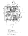
バルブタイミング制御装置は、図1に示すように内燃機関のシリンダヘッド(図示せず)に回転自在に支持されたカムシャフト1と、このカムシャフト1の前端部に結合された従動軸部材7(従動回転体)と、この従動軸部材7に必要に応じて相対回動できるように組み付けられ、チェーン(図示せず)を介してクランクシャフト(図示せず)に連係されるタイミングスプロケット2を外周に有する駆動リング3(駆動回転体)と、この駆動リング3と従動軸部材7の前方側(図1中左側)に配置され、両者3,1を相対回動させて組付角を操作する組付角変更手段4と、内燃機関の図外のシリンダヘッドとヘッドカバーの前面に跨って取り付けられて組付角変更手段4の前面と周域を覆う図外のVTCカバーと、を備えている。尚、組付角変更手段4は、回動操作力を発生する操作力発生部40と、その操作力発生部40で発生した回動操作力を駆動リング3と従動軸部材7の相対的な回転力に変換する変換機構部41と、によって構成されている。
As shown in FIG. 1, the valve timing control device includes a
駆動リング3は、段差状の挿通孔6を備えた略円板状に形成され、この挿通孔6部分が従動軸部材7(従動回転体)に回転可能に組み付けられている。そして、駆動リング3の前面(カムシャフト1と逆側の面)には、図2,図3に示すように、対面する平行な側壁を有する3つの径方向溝8(径方向ガイド)が同リング3のほぼ半径方向に沿うように形成されている。
The
また、従動軸部材7は、図1に示すように、カムシャフト1の前端部に突き合される基部側の外周に拡径部が形成されると共に、その拡径部よりも前方側の外周面に放射状に突出する三つのレバー9が一体に形成され、軸芯部を貫通するボルト10によってカムシャフト1に結合されている。各レバー9には、リンク11の基端がピン12によって枢支連結され、各リンク11の先端には前記各径方向溝8に摺動自在に係合する円柱状の突出部13が一体に形成されている。
Further, as shown in FIG. 1, the driven
各リンク11は、突出部13が対応する径方向溝8に係合した状態において、ピン12を介して従動軸部材7に連結されているため、リンク11の先端側が外力を受けて径方向溝8に沿って変位すると、駆動リング3と従動軸部材7はリンク11の作用でもって突出部13の変位に応じた方向及び角度だけ相対回動する。
Each
また、各リンク11の先端部には、軸方向前方側に開口する収容穴14が形成され、この収容穴14に、後述する渦巻き溝15(渦巻き状ガイド)に係合する係合ピン16と、この係合ピン16を前方側(渦巻き溝15側)に付勢するコイルばね17とが収容されている。尚、この実施形態の場合、リンク11の先端の突出部13と係合ピン16、コイルばね17等によって径方向に変位可能な可動案内部が構成されている。
In addition, a
一方、従動軸部材7のレバー9の突設位置よりも前方側には、円板状のフランジ壁を有する中間回転体18が軸受19を介して回転自在に支持されている。この中間回転体18のフランジ壁の後面側には断面半円状の前述の渦巻き溝15が形成され、この渦巻き溝15に、前記各リンク11の先端の係合ピン16が転動自在に案内係合されている。渦巻き溝15の渦巻きは、機関回転方向Rに沿って次第に縮径するように形成されている。したがって、各リンク11先端の係合ピン16が渦巻き溝15に係合した状態において、中間回転体18が駆動リング3に対して遅れ方向に相対回転すると、リンク11の先端部は径方向溝8に案内されつつ、渦巻き溝15の渦巻き形状に誘導されて半径方向内側に移動し、逆に、中間回転体18が進み方向に相対変位すると、半径方向外側に移動する。
On the other hand, an intermediate rotating
組付角変更手段4の変換機構部41は、以上説明した駆動リング3の径方向溝8、リンク11、突出部13、係合ピン16、レバー9、中間回転体18、渦巻き溝15等によって構成されている。この変換機構部41は、後述する操作力発生部40から中間回転体18にカムシャフト1に対する相対的な回動操作力が入力されると、その操作力が渦巻き溝15と係合ピン16の係合部を通してリンク11の先端を径方向に変位させ、このときリンク11が揺動してその揺動量に応じて駆動リング3と従動軸部材7を相対回動させる。
The
一方、操作力発生部5は、中間回転体18を駆動リング3に対して機関回転方向Rに付勢する付勢手段としてのゼンマイばね45と、中間回転体18を駆動リング3に対して機関回転方向Rと逆方向に作動させる(付勢手段に抗する力を発生する)アクチュエータとしてのヒステリシスブレーキ20と、を備え、ゼンマイばね45の付勢力とヒステリシスブレーキ20の作動力とのバランスによって中間回転体18を回動操作するようになっている。
On the other hand, the operating force generator 5 includes a
ゼンマイばね45は、駆動リング3に延設された円筒壁21にその外周端部が結合される一方、内周端部が中間回転体18の円筒状の基部に結合されている。
The
また、中間回転体18のカムシャフト1と逆側の端面には、封止壁46が一体に結合され、その封止壁46の外周面が前記円筒壁21の内面に摺動自在に密接している。
A
図1,図4に示すように、ヒステリシスブレーキ20は、非回転部材であるVTCカバーに取り付けられると共に、略円筒状の隙間を挟む対向面を備えた磁気誘導部材22と、前記対向面に設けられた内側極歯23、及び、外側極歯24と、磁気誘導部材22に取り付けられて内側極歯23と外側極歯24の間に磁界を生じさせる電磁コイル25と、前記両極歯23,24間に非接触状態で挿入配置された円筒状のヒステリシスリング26と、外周端がこのヒステリシスリング26に一体に結合された状態で中間回転体18に連結ピン47とゴムブッシュ48を介して結合された円環プレート27と、を備え、電磁コイル25がコントローラ42の出力信号によって適宜通電制御されるようになっている。
As shown in FIGS. 1 and 4, the
磁気誘導部材22の内側極歯23と外側極歯24は夫々軸方向に沿って延出する複数の極歯要素を有している。両極歯23,24の極歯要素は夫々円周方向に沿って配置され、極歯23,24の極歯要素相互は円周方向にオフセットされている。したがって、電磁コイル25が通電されると、両極歯23,24間には、オフセットした位置関係にある相手極歯要素に向かう磁界が発生する。
Each of the
ヒステリシスリング26は、磁気的ヒステリシス特性を有するヒステリシス材から成り、同リング26の回転中に内側極歯23と外側極歯24の間に磁界が発生すると、その磁界の向きとヒステリシスリング26内の磁束の向きとにずれが生じるようになっている。ヒステリシスブレーキ20は、このずれによって制動力を発生する。また、円環プレート27は、磁気誘導部材22の内周面に軸受28,29を介して支持された軸部材30に一体に結合されている。したがって、ヒステリシスリング20は、円環プレート27と軸部材30を介して磁気誘導部材22に相対回転可能に支持されている。
The
尚、図中43は、中間回転体13と駆動リング3の間に設けられ、両者13,3の相対回動範囲を規制するストッパである。
In the figure,
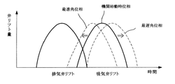
ここで、駆動リング3と従動軸部材7は、前記ストッパ43による中間回転体18の回動規制によって組付角が規制され、それによって両者の遅角側と進角側の最大角度位置である最遅角位置と最進角位置とが決定されているが、このバルブタイミング制御装置の場合、内燃機関の始動に適した組付角(確実な始動が可能な組付角)は前記最遅角位置と最進角位置のほぼ中間位置に設定されている。即ち、この実施形態のバルブタイミング制御装置は、吸気側の動弁系に適用されているため、時間軸に対する機関弁のリフト特性は、図6中の右側の山形の線図のようになるが、このとき内燃機関の始動に適した位相(図中実線)は、最遅角位相と最進角位相のほぼ中間の位相となっている。
Here, the assembly angle of the
また、内燃機関の始動時には、駆動リング3と従動軸部材7の組付角が始動に適した角度位置になっていなければならないが、この装置においては、内燃機関のクランキング時、つまり、イグニッションキー等による操作によって始動モータがオンにされているときに、コントローラ42から組付角変更手段4に組付角を始動に適した角度位置に制御すべく出力信号が発されるようになっている。
Further, when the internal combustion engine is started, the assembly angle of the
このバルブタイミング制御装置は以上のような構成であるため、クランクシャフトとカムシャフト1の回転位相(機関弁の開閉タイミング)を最進角側に変更する場合には、コントローラ42による制御によってヒステリシスブレーキ20に所定の電流を通電することにより、ゼンマイばね45の力に抗する制動力が円環プレート27から中間回転体18に連結ピン47とゴムブッシュ48を介して伝達される。これにより、中間回転体18が駆動リング3に対して逆方向に回転し、それによってリンク11の先端の係合ピン16が渦巻き溝15に誘導されてリンク11の先端部が径方向内側に変位し、このとき、図3に示すようにリンク11の作用によって駆動リング3と従動軸部材7の組付角が最進角位置に変更される。
Since this valve timing control device is configured as described above, the hysteresis brake is controlled by the
また、クランクシャフトとカムシャフト1の回転位相(機関弁の開閉タイミング)を最遅角側に変更する場合には、コントローラ42による制御によってヒステリシスブレーキ20の通電をオフにすることにより、中間回転体18がゼンマイばね45の力によって機関回転方向に回転させられる。すると、渦巻き溝15による係合ピン16の誘導によってリンク11の先端部が径方向外側に変位し、このとき、図2に示すようにリンク11の作用によって駆動リング3と従動軸部材7の組付角が最遅角位置に変更される。
Further, when the rotational phase of the crankshaft and the camshaft 1 (opening / closing timing of the engine valve) is changed to the most retarded angle side, the intermediate rotating body is turned off by turning off the
また、内燃機関の始動時には、前述のように始動モータがオンにされたときに、コントローラから組付角変更手段に組付角を始動に適した角度位置に変更すべく指令が発され、それによって迅速、かつ確実に内燃機関が始動される。 Further, when the internal combustion engine is started, when the starter motor is turned on as described above, a command is issued from the controller to the assembly angle changing means to change the assembly angle to an angle position suitable for starting. By this, the internal combustion engine is started quickly and reliably.
この内燃機関の始動時における具体的な制御は、例えば、図5のフローチャートに示すように行われる。 The specific control at the time of starting the internal combustion engine is performed as shown in the flowchart of FIG. 5, for example.
図5のフローにおいては、まず、S1において、始動モータがオンにされているかどうかが判断され、オンにされているときにのみ次のS2のステップに進み、S2においては、組付角を機関始動に適した組付角に変更すべく出力指令がコントローラ42から発され、それによってヒステリシスブレーキ20に所定の電流が通電される。S3においては、内燃機関が始動を完了したかどうかの判断が行われ、このとき始動が完了していればS4において通常のバルブタイミング制御に移行し、完了していなければS3の条件を満たすまでS2に戻るループが繰り返される。したがって、この処理によれば、内燃機関が確実に始動されるまでの間、最適な組付角(機関始動が可能な組付角)となるようにヒステリシスブレーキ20の通電制御が続けられ、内燃機関が始動されたところで通常のバルブタイミング制御に切換えられる。
In the flow of FIG. 5, first, in S1, it is determined whether or not the starter motor is turned on, and the process proceeds to the next step S2 only when it is turned on. An output command is issued from the
尚、S3の機関始動の完了の判断にあたっては、専用の検出機器を設けることも考えられるが、例えば、始動モータの通電信号がオフで、かつ、カム角センサからカムシャフト1の回転を示す信号が出力されているときに機関が始動したものと判断するようにしても良い。ただし、この場合、内燃機関の始動の有無を速やかに判断するため、カム角センサによる検出信号は角度変化に対して細かく設定することが望ましい。
In the determination of the completion of engine start in S3, a dedicated detection device may be provided. For example, a signal indicating the rotation of the
また、この実施形態の場合、組付角変更手段4は、ゼンマイばね45とヒステリシスブレーキ20の力のバランスによって組付角を操作するものであるため、クランクキング時等のカムシャフト1の回転速度がほぼ決まっている条件下においては、組付角をある角度位置に維持するのに要するヒステリシスブレーキ20の作動力(制動力)はゼンマイばね45の変形量との関係で一義的に決定される。このため、この実施形態においては、ヒステリシスブレーキ20に通電する電流値のみを管理することにより、機関始動に適した組付角に変更、乃至は保持するようにしている。したがって、この実施形態の場合、クランクシャフトとカムシャフト1の位相を逐次に検出して組付角操作を行う必要が無いため、コントローラ42による制御が容易となる。
Further, in the case of this embodiment, the assembly
尚、この発明の実施形態は以上で説明したものに限るものではなく、例えば、上記の実施形態においては、組付角変更手段の操作力発生部はゼンマイばねとヒステリシスブレーキによって構成したが、操作力発生部はこれら以外の付勢手段とアクチュエータによって構成するようにしても良い。また、操作力発生部は必ずしも付勢手段を用いる必要はなく、正転逆転操作ができるアクチュエータを用いれば付勢手段を無くすこともできる。 The embodiment of the present invention is not limited to the above-described embodiment. For example, in the above embodiment, the operating force generating portion of the assembly angle changing means is configured by a spring and a hysteresis brake. You may make it comprise a force generation part with an urging means and an actuator other than these. Further, the operating force generator does not necessarily need to use an urging means, and if an actuator capable of forward / reverse rotation is used, the urging means can be eliminated.
また、上記の実施形態においては、クランクキング時に、ヒステリシスブレーキに常に一定電流を通電するようにしたが、駆動リングと従動軸部材の組付角を検出する(例えば、クランク角センサとカム角センサの各検出値に基づいて組付角を算出する。)組付角検出手段を設け、その組付角検出手段によって検出した機関停止時の組付角をメモリに記憶させておき、機関を再始動させるときのクランクキング時に、メモリに記憶してある組付角のデータをコントローラに読み込み、そのデータに基づいてヒステリシスブレーキに通電する電流を適宜制御するようにしても良い。 In the above embodiment, a constant current is always supplied to the hysteresis brake during cranking, but the assembly angle between the drive ring and the driven shaft member is detected (for example, a crank angle sensor and a cam angle sensor). Assembling angles are calculated based on the detected values of each of the above.) An assembling angle detecting means is provided, and the assembling angle at the time of engine stop detected by the assembling angle detecting means is stored in the memory, and the engine is restarted. At the time of cranking at the time of starting, the assembly angle data stored in the memory may be read into the controller, and the current supplied to the hysteresis brake may be appropriately controlled based on the data.
この場合の電流制御は、例えば、機関の始動に適した組付角と機関停止時の組付角との乖離度合いに応じた大きさの電流を通電初期に流すようにすれば、より迅速に組付角を目的の角度位置に変更することができる。 In this case, the current control can be performed more quickly, for example, by supplying a current having a magnitude corresponding to the degree of deviation between the assembly angle suitable for starting the engine and the assembly angle when the engine is stopped. The assembly angle can be changed to a desired angular position.
次に、上記の各実施形態から把握し得る請求項に記載以外の発明について、以下にその作用効果と共に記載する。 Next, inventions other than those described in the claims that can be grasped from each of the above embodiments will be described below together with the effects thereof.
(イ)駆動回転体と従動回転体の組付角を検出する組付角検出手段を設け、内燃機関の停止時に、前記組付角検出手段によって検出した組付角を記憶させておき、機関を再始動させるときのクランクキング時に、前記記憶されている組付角に応じた作動信号を組付角変更手段に出力することを特徴とする請求項1または2に記載の内燃機関のバルブタイミング制御装置。
(A) An assembly angle detecting means for detecting the assembly angle of the driving rotating body and the driven rotating body is provided, and the assembly angle detected by the assembly angle detecting means when the internal combustion engine is stopped is stored, and the engine The valve timing of the internal combustion engine according to
この場合、機関停止時の組付角のデータを基にして、クランクキング時に、最も効率の良い作動信号を組付角変更手段に出力することができるため、内燃機関をより迅速に始動させることができる。 In this case, since the most efficient operation signal can be output to the assembly angle changing means at the time of cranking based on the assembly angle data when the engine is stopped, the internal combustion engine can be started more quickly. Can do.
(ロ)組付角変更手段の操作力発生部として電磁アクチュエータを用いたことを特徴とする請求項1、2、前記(イ)のいずれかに記載の内燃機関のバルブタイミング制御装置。
(B) The valve timing control device for an internal combustion engine according to any one of
この場合、操作力発生部に電磁アクチュエータを用いるため、通電とほぼ同時に大きな作動力を得ることができる。したがって、組付角変更手段を速やかに作動させ、より迅速に内燃機関を始動させることができる。 In this case, since an electromagnetic actuator is used for the operating force generation unit, a large operating force can be obtained almost simultaneously with energization. Therefore, the assembly angle changing means can be operated quickly and the internal combustion engine can be started more quickly.
(ハ)組付角変更手段は、
駆動回転体と従動回転体のいずれか一方に設けられた径方向ガイドと、
前記駆動回転体と従動回転体に対して相対回転可能に設けられ、前記径方向ガイドに対峙する側の面に渦巻き状ガイドを有する中間回転体と、
前記径方向ガイドと渦巻き状ガイドに変位可能に案内係合される可動案内部と、
前記駆動回転体と従動回転体のいずれか他方のものの回転中心から離間した部位と前記可動案内部とを揺動可能に連結するリンクと、
前記中間回転体を回動させる回動操作力を発生する操作力発生部と、を備え、
中間回転体に入力された回動操作力を、渦巻き状ガイドと可動案内部の係合部によって増幅して、駆動回転体と従動回転体の組付角操作力に変換することを特徴とする請求項1、2、前記(イ)、(ロ)のいずれかに記載の内燃機関のバルブタイミング制御装置。
(C) The assembly angle changing means is
A radial guide provided on one of the drive rotor and the driven rotor,
An intermediate rotator that is provided so as to be relatively rotatable with respect to the drive rotator and the driven rotator, and that has a spiral guide on a surface facing the radial guide;
A movable guide unit that is movably guided and engaged with the radial guide and the spiral guide;
A link that oscillates and couples the movable guide portion with a portion spaced from the rotation center of the other of the drive rotator and the driven rotator,
An operation force generating unit that generates a rotation operation force for rotating the intermediate rotating body,
The rotating operation force input to the intermediate rotating body is amplified by the engaging portion of the spiral guide and the movable guide portion, and converted into an assembly angle operating force of the driving rotating body and the driven rotating body. The valve timing control apparatus for an internal combustion engine according to any one of
この場合、操作力発生部から中間回転体に入力された回動操作力を増幅して駆動回転体と従動回転体の組付角操作力に変換するため、内燃機関がクランキング時にある場合であっても、駆動回転体と従動回転体の組付角を所望の組付角位置に確実に変更することができる。 In this case, when the internal combustion engine is at the time of cranking, the rotational operation force input from the operation force generator to the intermediate rotator is amplified and converted into the assembly angle operation force of the drive rotator and the driven rotator. Even if it exists, the assembly | attachment angle | corner of a drive rotary body and a driven rotary body can be reliably changed to a desired assembly | attachment angle position.
1…カムシャフト
3…駆動リング(駆動回転体)
4…組付角変更手段
7…従動軸部材(従動回転体)
20…ヒステリシスブレーキ(アクチュエータ)
42…コントローラ
45…ゼンマイばね(付勢手段)
DESCRIPTION OF
4 ... Assembly
20 ... Hysteresis brake (actuator)
42 ...
Claims (7)
前記内燃機関のクランクシャフトによって回転駆動される駆動回転体と、
カムシャフトに結合され、前記駆動回転体に対して相対回動できるように組み付けられた従動回転体と、
前記駆動回転体と従動回転体を相対回動させて両者の組付角を調整する組付角変更手段と、
通電することにより操作力を発生させ、該操作力により前記組付角変更手段を作動させるアクチュエータと、
前記駆動回転体と従動回転体の組付角を検出する組付角検出手段と、
内燃機関の停止時に、前記組付角検出手段によって検出した組付角を記憶するメモリーと、
内燃機関を始動させるための始動モータがオンされてから内燃機関が始動するまでの間に、最遅角位相の角度位置と最進角位相の角度位置の間に設定された前記内燃機関の始動に適した始動時組付角と前記メモリーに記憶された組付角とに基づいた指令信号を前記アクチュエータに出力して前記組付角変更手段によって前記始動時組付角に調整する制御手段と、を備えたことを特徴とする内燃機関のバルブタイミング制御装置。 A valve timing control device for an internal combustion engine that controls an engine valve in accordance with an operating state of the internal combustion engine,
A drive rotator driven to rotate by a crankshaft of the internal combustion engine;
A driven rotator coupled to a camshaft and assembled to be rotatable relative to the drive rotator;
An assembling angle changing means for adjusting the assembling angle between the driving rotating body and the driven rotating body relative to each other;
An actuator that generates an operating force by energization and activates the assembly angle changing means by the operating force;
An assembly angle detecting means for detecting an assembly angle of the drive rotor and the driven rotor;
A memory for storing an assembly angle detected by the assembly angle detection means when the internal combustion engine is stopped;
Starting of the internal combustion engine set between the angle position of the most retarded phase and the angle position of the most advanced angle phase between the time when the starting motor for starting the internal combustion engine is turned on and the time when the internal combustion engine is started Control means for outputting a command signal to the actuator based on the start-up assembly angle suitable for the engine and the assembly angle stored in the memory and adjusting the start-up assembly angle by the assembly-angle changing means; And a valve timing control device for an internal combustion engine.
前記制御手段は、前記内燃機関を始動させるための始動モータがオンされてから内燃機関が始動するまでの間に、前記始動時組付角と前記メモリーに記憶された組付角の乖離度合いに応じた指令信号を前記アクチュエータに出力して前記組付角変更手段によって前記始動時組付角に調整することを特徴とする内燃機関のバルブタイミング制御装置。 The valve timing control apparatus for an internal combustion engine according to claim 1,
The control means sets the degree of divergence between the assembling angle at the time of starting and the assembling angle stored in the memory from when the starting motor for starting the internal combustion engine is turned on until the internal combustion engine is started. A valve timing control device for an internal combustion engine, wherein a corresponding command signal is output to the actuator and adjusted to the assembly angle at start by the assembly angle changing means.
前記組付角検出手段は、カム角センサとクランク角センサとによって構成され、前記始動モータがオフされかつ前記カム角センサからカムシャフトの回転角度を検出した信号が出力されているときに前記内燃機関が始動したと判断することを特徴とする内燃機関のバルブタイミング制御装置。 The valve timing control apparatus for an internal combustion engine according to claim 1,
The assembly angle detection means includes a cam angle sensor and a crank angle sensor, and the internal combustion engine is turned off when the start motor is turned off and a signal indicating the rotation angle of the camshaft is output from the cam angle sensor. A valve timing control device for an internal combustion engine, characterized in that it is determined that the engine has started.
カムシャフトに結合され、前記駆動回転体に対して相対回動できるように組み付けられた従動回転体と、
前記駆動回転体と従動回転体とを相対回動させて該両者の組付角を操作する組付角変更手段と、
通電することにより操作力を発生させ、該操作力により前記組付角変更手段を作動させるアクチュエータと、
前記駆動回転体と従動回転体の組付角を検出する組付角検出手段と、
を備えたバルブタイミング変更機構を制御するコントローラであって、
内燃機関の停止時に、前記組付角検出手段によって検出した組付角を記憶しておき、
内燃機関を始動させるための始動モータがオンされてから内燃機関が始動するまでの間に、最遅角位相の角度位置と最進角位相の角度位置の間に設定された前記内燃機関の始動に適した始動時組付角と前記記憶された組付角とに基づいた指令信号を前記アクチュエータに出力して前記組付角変更手段によって前記始動時組付角に調整することを特徴とするバルブタイミング変更機構を制御するコントローラ。 A drive rotor that is driven to rotate by the crankshaft of the internal combustion engine;
A driven rotator coupled to a camshaft and assembled to be rotatable relative to the drive rotator;
An assembling angle changing means for operating the assembling angle of the drive rotator and the driven rotator relative to each other;
An actuator that generates an operating force by energization and activates the assembly angle changing means by the operating force;
An assembly angle detecting means for detecting an assembly angle of the drive rotor and the driven rotor;
A controller for controlling a valve timing changing mechanism comprising:
Storing the assembly angle detected by the assembly angle detection means when the internal combustion engine is stopped;
Starting of the internal combustion engine set between the angle position of the most retarded phase and the angle position of the most advanced angle phase between the time when the starting motor for starting the internal combustion engine is turned on and the time when the internal combustion engine is started And a command signal based on the stored assembly angle and the stored assembly angle are output to the actuator and adjusted to the startup assembly angle by the assembly angle changing means. A controller that controls the valve timing change mechanism.
内燃機関を始動させるための始動モータがオンされてから内燃機関が始動するまでの間に、前記始動時組付角と前記記憶された組付角の乖離度合いに応じた指令信号を前記アクチュエータに出力して組付角変更手段によって始動時組付角に調整することを特徴とするバルブタイミング変更機構を制御するコントローラ。 In the controller of the valve timing changing mechanism according to claim 4,
A command signal corresponding to the degree of divergence between the start-up assembly angle and the stored assembly angle is supplied to the actuator between the time when the start motor for starting the internal combustion engine is turned on and the time when the internal combustion engine is started. A controller for controlling a valve timing changing mechanism that outputs and adjusts to an assembling angle at start-up by an assembling angle changing means.
前記組付角検出手段は、カム角センサとクランク角センサとによって構成され、前記始動モータがオフされかつ前記カム角センサからカムシャフトの回転角度を検出した信号が出力されているときに前記内燃機関が始動したと判断することを特徴とするバルブタイミング変更機構を制御するコントローラ。 In the controller for controlling the valve timing changing mechanism according to claim 4,
The assembly angle detection means includes a cam angle sensor and a crank angle sensor, and the internal combustion engine is turned off when the start motor is turned off and a signal indicating the rotation angle of the camshaft is output from the cam angle sensor. A controller for controlling a valve timing changing mechanism characterized in that it is determined that the engine has started.
カムシャフトに結合され、前記駆動回転体に対して相対回動できるように組み付けられた従動回転体と、
前記駆動回転体と従動回転体とを相対回動させて該両者の組付角を調整する組付角変更手段と、
通電することにより操作力を発生させ、該操作力により前記組付角変更手段を作動させるアクチュエータと、
前記駆動回転体と従動回転体の組付角を検出する組付角検出手段と、
を備えた内燃機関のバルブタイミング制御装置のコントローラであって、
内燃機関を始動させるための始動モータがオンされてから内燃機関が始動するまでの間に、最遅角位相の角度位置と最進角位相の角度位置の間に設定された前記内燃機関の始動に適した始動時組付角と前記内燃機関の停止時の組付角とに基づいた指令信号を前記アクチュエータに出力して前記組付角変更手段によって前記始動時組付角に調整する制御手段と、
を備えたことを特徴とする内燃機関のバルブタイミング制御装置のコントローラ。 A drive rotor that is driven to rotate by the crankshaft of the internal combustion engine;
A driven rotator coupled to a camshaft and assembled to be rotatable relative to the drive rotator;
An assembling angle changing means for adjusting the assembling angle between the driving rotating body and the driven rotating body relative to each other;
An actuator that generates an operating force by energization and activates the assembly angle changing means by the operating force;
An assembly angle detecting means for detecting an assembly angle of the drive rotor and the driven rotor;
A controller for a valve timing control device for an internal combustion engine comprising:
During a period from the starter motor is turned on for starting the internal combustion engine until the starting the internal combustion engine, the starting of the internal combustion engine, which is set between the angular position of the angular position and the most advanced angle phase of the most retarded angle phase A control means for outputting a command signal based on an assembly angle at start suitable for the engine and an assembly angle when the internal combustion engine is stopped to the actuator, and adjusting the assembly angle at the start by the assembly angle changing means When,
A controller for a valve timing control device for an internal combustion engine, comprising:
Priority Applications (1)
| Application Number | Priority Date | Filing Date | Title |
|---|---|---|---|
| JP2008018463A JP4606473B2 (en) | 2008-01-30 | 2008-01-30 | Valve timing control device for internal combustion engine, controller for the valve timing control device, and controller used for valve timing changing mechanism |
Applications Claiming Priority (1)
| Application Number | Priority Date | Filing Date | Title |
|---|---|---|---|
| JP2008018463A JP4606473B2 (en) | 2008-01-30 | 2008-01-30 | Valve timing control device for internal combustion engine, controller for the valve timing control device, and controller used for valve timing changing mechanism |
Related Parent Applications (1)
| Application Number | Title | Priority Date | Filing Date |
|---|---|---|---|
| JP2002299784A Division JP4163482B2 (en) | 2002-10-15 | 2002-10-15 | Valve timing control device for internal combustion engine |
Publications (3)
| Publication Number | Publication Date |
|---|---|
| JP2008111445A JP2008111445A (en) | 2008-05-15 |
| JP2008111445A5 JP2008111445A5 (en) | 2009-07-16 |
| JP4606473B2 true JP4606473B2 (en) | 2011-01-05 |
Family
ID=39444066
Family Applications (1)
| Application Number | Title | Priority Date | Filing Date |
|---|---|---|---|
| JP2008018463A Expired - Fee Related JP4606473B2 (en) | 2008-01-30 | 2008-01-30 | Valve timing control device for internal combustion engine, controller for the valve timing control device, and controller used for valve timing changing mechanism |
Country Status (1)
| Country | Link |
|---|---|
| JP (1) | JP4606473B2 (en) |
Cited By (1)
| Publication number | Priority date | Publication date | Assignee | Title |
|---|---|---|---|---|
| US11002163B2 (en) | 2018-12-21 | 2021-05-11 | Denso Corporation | Valve timing controller and valve timing control method |
Citations (3)
| Publication number | Priority date | Publication date | Assignee | Title |
|---|---|---|---|---|
| JPH09195840A (en) * | 1996-01-24 | 1997-07-29 | Nissan Motor Co Ltd | Fuel injection control device of internal combustion engine furnishing variable moving valve mechanism |
| JP2001082191A (en) * | 1999-09-20 | 2001-03-27 | Unisia Jecs Corp | Control position detecting device for variable valve system of internal combustion engine |
| JP2002227668A (en) * | 2001-01-31 | 2002-08-14 | Mitsubishi Electric Corp | Valve timing control device for internal combustion engine |
-
2008
- 2008-01-30 JP JP2008018463A patent/JP4606473B2/en not_active Expired - Fee Related
Patent Citations (3)
| Publication number | Priority date | Publication date | Assignee | Title |
|---|---|---|---|---|
| JPH09195840A (en) * | 1996-01-24 | 1997-07-29 | Nissan Motor Co Ltd | Fuel injection control device of internal combustion engine furnishing variable moving valve mechanism |
| JP2001082191A (en) * | 1999-09-20 | 2001-03-27 | Unisia Jecs Corp | Control position detecting device for variable valve system of internal combustion engine |
| JP2002227668A (en) * | 2001-01-31 | 2002-08-14 | Mitsubishi Electric Corp | Valve timing control device for internal combustion engine |
Cited By (2)
| Publication number | Priority date | Publication date | Assignee | Title |
|---|---|---|---|---|
| US11002163B2 (en) | 2018-12-21 | 2021-05-11 | Denso Corporation | Valve timing controller and valve timing control method |
| DE102019133630B4 (en) | 2018-12-21 | 2023-07-27 | Denso Corporation | VALVE TIMING CONTROL DEVICE AND METHOD FOR CONTROLLING VALVE TIMING |
Also Published As
| Publication number | Publication date |
|---|---|
| JP2008111445A (en) | 2008-05-15 |
Similar Documents
| Publication | Publication Date | Title |
|---|---|---|
| JP3986371B2 (en) | Valve timing control device for internal combustion engine | |
| JP2008002324A (en) | Phase angle detector and valve timing controller of internal-combustion engine using the same | |
| JP4156346B2 (en) | Valve timing control device for internal combustion engine | |
| JP2005226543A (en) | Learning device for variable valve system | |
| JP2006299867A (en) | Valve timing control device for internal combustion engine | |
| JP2009222037A (en) | Valve timing regulating device | |
| JP3736627B2 (en) | Valve timing adjustment device | |
| JP2009222036A (en) | Valve timing control device of internal combustion engine | |
| JP4295081B2 (en) | Valve timing control device for internal combustion engine | |
| JP2005146993A (en) | Valve timing control device for internal combustion engine | |
| JP4606473B2 (en) | Valve timing control device for internal combustion engine, controller for the valve timing control device, and controller used for valve timing changing mechanism | |
| JP4163482B2 (en) | Valve timing control device for internal combustion engine | |
| JP5379555B2 (en) | Valve timing control device for internal combustion engine | |
| JP2009091928A (en) | Valve timing control device for internal combustion engine | |
| JP4698696B2 (en) | Valve timing control device for internal combustion engine and its controller | |
| JP4233308B2 (en) | Valve timing control device for internal combustion engine | |
| JP4109972B2 (en) | Valve timing control device for internal combustion engine | |
| JP4299164B2 (en) | Control device for variable valve timing mechanism | |
| JP4109967B2 (en) | Valve timing control device for internal combustion engine | |
| JP2006274957A (en) | Valve timing control device for internal combustion engine | |
| JP2005299605A (en) | Valve timing control device for internal combustion engine | |
| JP4076398B2 (en) | Valve timing control device for internal combustion engine | |
| JP3989764B2 (en) | Valve timing control device for internal combustion engine | |
| JP2008082343A (en) | Valve timing control device for internal combustion engine | |
| JP2008101611A (en) | Variable valve gear for internal combustion engine |
Legal Events
| Date | Code | Title | Description |
|---|---|---|---|
| A621 | Written request for application examination |
Free format text: JAPANESE INTERMEDIATE CODE: A621 Effective date: 20080130 |
|
| A521 | Written amendment |
Free format text: JAPANESE INTERMEDIATE CODE: A523 Effective date: 20090515 |
|
| A521 | Written amendment |
Free format text: JAPANESE INTERMEDIATE CODE: A523 Effective date: 20090529 |
|
| A711 | Notification of change in applicant |
Free format text: JAPANESE INTERMEDIATE CODE: A712 Effective date: 20090922 |
|
| RD03 | Notification of appointment of power of attorney |
Free format text: JAPANESE INTERMEDIATE CODE: A7423 Effective date: 20090922 |
|
| A131 | Notification of reasons for refusal |
Free format text: JAPANESE INTERMEDIATE CODE: A131 Effective date: 20100216 |
|
| A521 | Written amendment |
Free format text: JAPANESE INTERMEDIATE CODE: A523 Effective date: 20100326 |
|
| TRDD | Decision of grant or rejection written | ||
| A01 | Written decision to grant a patent or to grant a registration (utility model) |
Free format text: JAPANESE INTERMEDIATE CODE: A01 Effective date: 20100928 |
|
| A01 | Written decision to grant a patent or to grant a registration (utility model) |
Free format text: JAPANESE INTERMEDIATE CODE: A01 |
|
| A61 | First payment of annual fees (during grant procedure) |
Free format text: JAPANESE INTERMEDIATE CODE: A61 Effective date: 20101005 |
|
| R150 | Certificate of patent or registration of utility model |
Ref document number: 4606473 Country of ref document: JP Free format text: JAPANESE INTERMEDIATE CODE: R150 Free format text: JAPANESE INTERMEDIATE CODE: R150 |
|
| FPAY | Renewal fee payment (event date is renewal date of database) |
Free format text: PAYMENT UNTIL: 20131015 Year of fee payment: 3 |
|
| FPAY | Renewal fee payment (event date is renewal date of database) |
Free format text: PAYMENT UNTIL: 20131015 Year of fee payment: 3 |
|
| FPAY | Renewal fee payment (event date is renewal date of database) |
Free format text: PAYMENT UNTIL: 20141015 Year of fee payment: 4 |
|
| R250 | Receipt of annual fees |
Free format text: JAPANESE INTERMEDIATE CODE: R250 |
|
| R250 | Receipt of annual fees |
Free format text: JAPANESE INTERMEDIATE CODE: R250 |
|
| R250 | Receipt of annual fees |
Free format text: JAPANESE INTERMEDIATE CODE: R250 |
|
| R250 | Receipt of annual fees |
Free format text: JAPANESE INTERMEDIATE CODE: R250 |
|
| R250 | Receipt of annual fees |
Free format text: JAPANESE INTERMEDIATE CODE: R250 |
|
| R250 | Receipt of annual fees |
Free format text: JAPANESE INTERMEDIATE CODE: R250 |
|
| LAPS | Cancellation because of no payment of annual fees |