JP4601774B2 - Winding device - Google Patents
Winding device Download PDFInfo
- Publication number
- JP4601774B2 JP4601774B2 JP2000202799A JP2000202799A JP4601774B2 JP 4601774 B2 JP4601774 B2 JP 4601774B2 JP 2000202799 A JP2000202799 A JP 2000202799A JP 2000202799 A JP2000202799 A JP 2000202799A JP 4601774 B2 JP4601774 B2 JP 4601774B2
- Authority
- JP
- Japan
- Prior art keywords
- winding
- coil bobbin
- unit
- winding shaft
- wire
- Prior art date
- Legal status (The legal status is an assumption and is not a legal conclusion. Google has not performed a legal analysis and makes no representation as to the accuracy of the status listed.)
- Expired - Lifetime
Links
Images
Landscapes
- Coil Winding Methods And Apparatuses (AREA)
Description
【0001】
【発明の属する技術分野】
この発明は、コイルボビンに対し線材の巻き付け作業など各種の作業を順次行う巻線装置に関する。
【0002】
【従来の技術】
従来から、コイルボビンに対して線材の巻き付けおよび、巻き付けた線材の端部をコイルボビンの端子に半田付けするなど各種の作業を一貫して行う巻線装置が知られている。この巻線装置は、各種の作業ユニットをコンベアに沿って順次配列し、パレットに搭載したコイルボビンをコンベアによって移動させている。各種作業ユニットの位置にコイルボビンが到達したら、パレットをストッパなどで停止、位置決めした後、パレットからコイルボビンを作業ユニット側に受け渡す。作業ユニットがコイルボビンに対し所定の作業を終了したら、再びコイルボビンをコンベア上のパレットに戻し、パレットのストッパを解除して、そのパレットを次の作業ユニットへ移動させる。
【0003】
【発明が解決しようとする課題】
しかしながら、上記した従来の巻線装置は、コンベア上のパレットと作業ユニットとの間で、コイルボビンを受け渡す作業が必要なことから、受け渡し時にミスが発生する場合があり、特にパレットから作業ユニットへの受け渡し時にミスが発生すると、作業ユニットで正常な作業が行われず、不良品を作ってしまうという問題がある。
【0004】
また、受け渡しに要する時間も必要になり、作業時間がその分余計にかかる上、受け渡しのための専用の受け渡しユニットが必要となり、その分費用がかかるという問題もある。
【0005】
そこで、この発明は、コイルボビンの受け渡し作業を必要とすることなく、コイルボビンに対して線材の巻き付け作業を始め各種の作業を一貫して行えるようにすることを目的としている。
【0006】
【課題を解決するための手段】
前記目的を達成するために、請求項1の発明は、コイルボビンを保持して回転可能な巻軸と、この巻軸を上下方向および水平方向に移動させる移動機構とを有し、前記移動機構による前記巻軸の水平方向への移動方向に沿って、前記巻軸に保持されたコイルボビンに対して線材を巻き付ける巻線ユニットならびに前記巻軸に保持されたコイルボビンに対する各種の作業ユニットをそれぞれ配列した巻線装置であって、前記巻線ユニットならびに前記作業ユニットを、装置基台のベース部上に配置するとともに、このベース部の側縁から立設される上部フレームの前記ベース部側の前面に、前記移動機構を配置した構成としてある。
【0007】
このような構成の巻線装置によれば、巻軸に保持されたコイルボビンが、移動機構によって水平方向に移動することで、巻線ユニットおよび各種作業ユニットに対応する位置となる。そして、各ユニットにおいて巻軸に保持されたコイルボビンが、移動機構によって適宜上下方向に移動して、各作業に適した上下位置となる。巻線ユニットにおいては、巻軸自身が回転して線材がコイルボビンに巻き付けられる。
【0008】
請求項2の発明は、請求項1の発明の構成において、巻軸と直交する軸回りに前記巻軸を回転させるインデックス機構を移動機構により上下方向および水平方向に移動可能に設けた構成としてある。
【0009】
上記構成によれば、巻軸に保持されたコイルボビンが、巻線ユニットおよび各種作業ユニットにおけるそれぞれの作業に適した姿勢となるように、インデックス機構によって回転する。
【0010】
請求項3の発明は、請求項1または2の発明の構成において、巻軸は、コイルボビンに設けた保持穴に挿入して保持する構成である。
【0011】
上記構成によれば、コイルボビンは、巻軸を保持穴に挿入するだけで容易に巻軸に保持される。
【0012】
請求項4の発明は、請求項3の発明の構成において、保持穴が上方を向いた状態のコイルボビンがセットされるワークセット部を、巻線ユニットによる巻線作業の前工程としてインデックス機構の水平方向への移動方向に沿って配置した構成としてある。
【0013】
上記構成によれば、コイルボビンは、巻軸が挿入される保持穴が上方を向いた状態でワークセット部にセットされ、この状態で巻軸が、移動機構によってインデックス機構とともに下降することで、保持穴に挿入されて、コイルボビンが巻軸に保持された状態となる。
【0014】
請求項5の発明は、請求項4の発明の構成において、ワークセット部にコイルボビンを順次送り込むパーツフィーダを設けた構成としてある。
【0015】
上記構成によれば、コイルボビンは、パーツフィーダからワークセット部に順次送り込まれる。
【0016】
請求項6の発明は、請求項3の発明の構成において、巻軸に保持されたコイルボビンを、巻軸と平行に移動して巻軸から引き抜く排出具を備えた排出ユニットを、各種の作業ユニットによる各種作業の後工程としてインデックス機構の水平方向への移動方向に沿って配置した構成としてある。
【0017】
上記構成によれば、排出具が、コイルボビンを移動させるべく巻軸と平行に移動することで、コイルボビンが巻軸から引き抜かれる。
【0018】
請求項7の発明は、請求項1ないし6のいずれかの発明の構成において、各種の作業ユニットは、コイルボビンに巻かれた線材を前記コイルボビンの端子に対して半田付けする半田付けユニットと、半田付けされたコイルボビンの抵抗値を測定する検査ユニットとから構成してある。
【0019】
上記構成によれば、巻線ユニットによって線材が巻き付けられたコイルボビンが、半田ユニットまで移動し、ここで巻軸に保持されたまま、コイルボビンに巻かれた線材が端子に半田付けされる。半田付け作業後、コイルボビンは検査ユニットまで移動し、コイルボビンの抵抗値が巻軸に保持されたまま測定される。
【0020】
請求項8の発明は、請求項1ないし7のいずれかの発明の構成において、巻線ユニットは、線材を保持する線材保持部と、前記線材を案内するノズルと、このノズルを三次元方向に移動させる三次元移動機構とを備えた構成としてある。
【0021】
上記構成によれば、線材は、線材保持部に保持された状態で、三次元方向に適宜移動するノズルに案内されて順次繰り出され、回転する巻軸に巻き付けられる。
【0022】
請求項9の発明は、請求項7の発明の構成において、半田付けユニットは、巻軸に保持されているコイルボビンの下方に半田槽が配置される構成としてある。
【0023】
上記構成によれば、コイルボビンを保持している巻軸が水平となっている状態で、コイルボビンの端子が下部位置となるよう自身が軸周りに回転するとともに、移動機構によって下方に移動することで、コイルボビンの端子が半田槽に浸されて半田付けされる。
【0024】
請求項10の発明は、請求項7の発明の構成において、検査ユニットは、巻軸に保持されているコイルボビンの下方にプローブが配置される構成としてある。
【0025】
上記構成によれば、コイルボビンを保持している巻軸が水平でかつ、コイルボビンの端子が下部位置となっている状態で、コイルボビンが移動機構によって下方に移動することで、コイルボビンの端子がプローブに接触して抵抗値が測定される。
【0026】
【発明の実施の形態】
以下、この発明の実施の形態を図面に基づき説明する。
【0027】
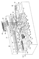
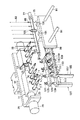
図1は、この発明の実施の一形態を示す巻線装置の全体構成を示す斜視図で、図2は、コイルボビン1を保持する巻軸としての複数の巻治具3周辺の拡大された斜視図である。巻治具3は、先端が先細のテーパ部を備えてスピンドル軸5に挿入され、止めねじ7によって固定されている。一方コイルボビン1は、保持穴9を備え、この保持穴9に巻治具3が挿入されることで巻治具3に保持される。
【0028】
各スピンドル軸5の基端部は、インデックス機構11におけるハウジング13の内部に配置され、その基端部にはプーリ15が装着されている。隣接するスピンドル軸5のプーリ15相互は、歯付きベルト17によって連結されている。ハウジング13の図中で右側の端部には、スピンドルモータ19が設けられ、スピンドルモータ19は、図中で右側端部のスピンドル軸5に、図示しないギアなどを介して連動連結されている。すなわち、スピンドルモータ19の駆動によって各スピンドル軸5が同期して回転する。
【0029】
インデックス機構11のハウジング13の図中で左側の端部には、インデックスモータ21の駆動軸23が連結され、インデックスモータ21の駆動によりハウジング13が、巻治具3と直交する軸回りにスピンドル軸5および巻治具3とともに回転する。
【0030】
インデックスモータ21は、上下移動ブラケット25に取り付けられ、上下移動ブラケット25は、図1に示してある水平移動ブラケット27に対し、上下ガイドレール29にガイドされて上下方向に移動する。水平移動ブラケット27には上下移動モータ31が設置され、上下移動モータ31の駆動軸は、上下移動ブラケット25に螺合しているボールねじ33に連結されている。すなわち、上下移動モータ31の駆動により上下移動ブラケット25が上下ガイドレール29に沿って上下方向に移動する。
【0031】
水平移動ブラケット27は、装置基台35の上部フレーム37の前面に左右方向に延長して設けられた取付板39上の水平ガイドレール41にガイドされて水平方向に移動する。取付板39上の図中で右側の端部には、水平移動モータ43が設置され、水平移動モータ43の駆動軸は、水平移動ブラケット27に螺合しているボールねじ45に連結されている。ボールねじ45の端部は、取付板39の図中で左側の端部に設けられたねじ保持具47に回転可能に保持されている。すなわち、水平移動モータ43の駆動により水平移動ブラケット27が水平ガイドレール41に沿って水平方向に移動する。
【0032】
上記した上下移動モータ31,上下ガイドレール29,水平移動モータ43、水平ガイドレール41およびボールねじ33,45などにより、インデックス機構11を上下方向および水平方向に移動させる移動機構を構成している。
【0033】
装置基台35のベース部48上には、図1中で右側の端部から、パーツフィーダ49、ワークセット部50,巻線ユニット51,半田付けユニット53、検査ユニット55および排出ユニット57が、インデックス機構11の水平移動方向に沿って配置されている。半田付けユニット53および検査ユニット55は、各種の作業ユニットを構成している。
【0034】
パーツフィーダ49は、コイルボビン1をワークセット部50まで順次送り出す。ワークセット59上でのコイルボビン1は、保持穴9が上方を向いた状態であり、複数の巻治具3に対応してその配列方向に沿ってセットされる。
【0035】
巻線ユニット51は、装置基台35における上部フレーム37の上部に設けた線材スプール61からの線材63を、テンション装置65およびガイドローラ67を経由して、ノズル69に挿入し、このノズル69の先端(下端)から線材63を繰り出す構成であり、ノズル69から繰り出された線材63の端部付近は、線材保持部としての線材クランプ71により保持されている。
【0036】
ノズル69は、複数の巻治具3に対応して複数のものがノズル保持ロッド73に直線状に保持固定されており、ノズル保持ロッド73は、ノズル保持ブラケット75に回転可能に保持されている。ノズル保持ブラケット75の一方の端部には、ノズル保持ロッド73を旋回させるノズル旋回シリンダ77が装着されている。
【0037】
ノズル保持ブラケット75は、図1に示してあるように、三次元移動機構79によって、上部フレーム37に対して接近離反する方向に対応するX方向、インデックス機構11の水平移動方向に対応するY方向および、上下方向に対応するZ方向の三次元方向に移動可能である。三次元移動機構79は、装置基台35上に固定されたベース板81上のガイドレール83に沿って枠体85がY方向に移動可能であり、この枠体85は、ベース板81上に設置されたY方向モータ87および、Y方向モータ87によって回転し枠体85に螺合しているボールねじ89によって移動する。
【0038】
枠体85には、X方向に延長される2本のガイドロッド91がその軸方向に移動可能に挿入され、ガイドロッド91の両端は枠体85の外部に突出している。枠体85内における2本のガイドロッド91には、ブロック93が固定されている。ブロック93の中央には、ガイドロッド91と平行なボールねじ95が螺合し、ボールねじ95の基端側は枠体85の外部に装着されたX方向モータ97に連結され、同先端側は、枠体85に対して回転可能に支持されている。すなわち、X方向モータ97の駆動によりブロック93が2本のガイドロッド91とともにX方向に移動する。
【0039】
上記した2本のガイドロッド91の上部フレーム37側の端部は、上下可動板99に連結され、この上下可動板99に対し、前記したノズル保持ブラケット75がガイドレール101に沿って上下方向に移動可能となっている。上下可動板99のノズルブラケット75側には、図示していないがZ方向モータが設置され、このZ方向モータの駆動軸は、ノズル保持ブラケット75に螺合している上下方向に延長されるボールねじ103に連結されている。すなわち、Z方向モータの駆動により、ノズル保持ブラケット75が、ノズル69およびノズル保持ロッド73とともにZ(上下)方向に移動する。
【0040】
線材クランプ71は、各ノズル69に対応して設けられ、装置基台35のベース部48上に設置されたクランプ支持台105に支持されている。クランプ支持台105は、左右一対の側板107と、各側板107の上端に装着される上板109とから構成され、上板109に線材クランプ71を構成する固定クランプ板111および可動クランプ板113がそれぞれ設けられている。可動クランプ板113は、上板109に形成した貫通孔115に上下に突出するよう挿入されている。一方、側板107の一方には、クランプシリンダ117が装着され、クランプシリンダ117のピストンロッド119が、前記可動クランプ板113の下方への突出した部位に連結されている。すなわち、クランプシリンダ117の駆動により、可動クランプ板113が上板109の長手方向に移動して、固定クランプ板111との間で線材63をクランプ、アンクランプする。
【0041】
クランプ支持台105に隣接してその上部フレーム37側には、線材63をカットするカット鋏121が設置されている。カット鋏121は、支持板123上に固定された駆動部125によって駆動して線材63をカットするもので、装置基台35のベース部48上に設置されたカット鋏支持台127上のシリンダ129により、支持板123とともに上下動する。
【0042】
なお、上記した線材クランプ71およびカット鋏121は、それらを支持するクランプ支持台105およびカット鋏支持台127などとともに図1では省略してある。
【0043】
半田付けユニット53は、装置基台35のベース部48上に支持台131が設置され、この支持台131上に半田槽133が設けられている。半田槽133の下面には、下方に向けて延長されて支持台131に対して上下動可能な一対のガイドロッド135が取り付けられている。一方、支持台131の下面には、モータ137が装着され、モータ137の駆動軸に連結する図示しないボールねじが、支持台131を貫通してその先端が半田槽133に螺合している。すなわち、モータ137の駆動により半田槽133が上下動する。
【0044】
また、上記した半田付けユニット53は、半田槽133に満たされた半田液の表面に浮遊する半田かすなどの異物を除去する異物除去具141が、前記巻線ユニット51におけるX方向に移動可能に設けられている。異物除去具141は、支持台131上に設置された一対のブラケット143,145に対して前記X方向に移動可能に支持された2本のガイドロッド146の端部に連結され、このガイドロッド146に固定してある連結板147に、ブラケット143に装着してあるシリンダ149のピストンロッドの先端が連結されている。すなわち、シリンダ149の駆動により、異物除去具141がX方向に移動する。
【0045】
検査ユニット55は、巻治具3と倍数のプローブ153が、複数の巻治具3の配列方向に沿って配置され、これら各プローブ153は、装置基台35のベース部48上に設置された支持台155に、スプリング157によって上方に付勢された状態で取り付けられている。各プローブ153は、リード線159を介し、ベース部48上に設置されている抵抗チェッカ161に接続されている。
【0046】
排出ニット57は、良品排出部163と不良品排出部165とに分かれており、いずれもコイルボビン1を巻治具3から引き抜くためのフォーク状の排出具167,169を、巻治具3と同数それぞれ備えるとともに、排出されたコイルボビン1を収容する収容箱171,173をそれぞれ備えている。排出具167,169は、装置基台35のベース部48上に設置した支持ブラケット175に取り付けたシリンダ177,179によって、互いに別々に前記X方向に移動する。
【0047】
次に、上記した構成の巻線装置の動作を説明する。パーツフィーダ49からワークセット部50に送り出されたコイルボビン1は、巻治具3と同数のものが、保持穴9が上方を向いた状態となってセットされている。ここで、水平移動ブラケット27は、図1に示した位置より右方向へ移動して、巻治具3がワークセット部50に対応する位置となるようにするとともに、上方に移動させておく。この状態で巻治具3は、インデックスモータ21の駆動により、先端が下方を向く状態となるよう図1および図2の状態から90度回転させ、この状態からインデックス機構11を上下移動モータ31の駆動により下方に移動させることで、各巻治具3がワークセット部50上のコイルボビン1の保持穴9に挿入され、これによりコイルボビン1が巻治具3によって保持される。
【0048】
コイルボビン1を巻治具3に保持させたインデックス機構11は、上下移動モータ31の駆動により上昇し、さらにインデックスモータ21の駆動により巻治具3が図1および図2に示してある水平状態となるようにする。その後さらに、水平移動モータ43の駆動により、コイルボビン1が巻線ユニット51に対応する位置となるようインデックス機構11を水平移動させる。一方、パーツフィーダ49は、次の複数のコイルボビン1をワークセット部50に送り出す作業を行う。
【0049】
巻線ユニット51では、ノズル69から繰り出されている線材63は、線材クランプ71によってクランプされており、この状態で三次元移動機構79およびノズル旋回シリンダ77の適宜の駆動により、ノズル69がコイルボビン1の巻始め端子1aに線材63を絡ませる。その後、線材クランプ71と巻始め端子1aとの間の線材63を、巻始め端子1aに近い位置でカット鋏121によりカットする。このカット作業は、シリンダ129の駆動によりカット鋏121を適宜上昇させるなどして行う。
【0050】
次に、ノズル69をコイルボビン1の巻胴部に移動させてから、スピンドルモータ19の駆動によって巻治具3を回転させることで、ノズル69から繰り出される線材63をコイルボビン1の巻胴部に巻き付ける。このとき、コイルボビン1の回転に同期させて、ノズル69をX方向に移動させることで線材63を巻胴部に整列状態で巻き付けることが可能となる。
【0051】
巻胴部に線材63を所定回数巻き付けたら、線材63をコイルボビン1の巻終わり端子1bに絡ませた後、ノズル69と巻終わり端子1bとの間の線材63を線材クランプ71によりクランプし、適宜上昇させたカット鋏121により、線材クランプ71と巻終わり端子1bとの間の線材63を、巻終わり端子1b近くでカットする。その後、X方向モータ97の駆動によりノズル69をノズル保持ブラケット75などとともに後退させておく。
【0052】
巻線ユニット51による巻線作業が終了したら、インデックス機構11は、水平移動モータ43の駆動により水平方向に移動して半田付けユニット53に達する。半田付けユニット53では、スピンドルモータ19の駆動により、コイルボビン1をスピンドル軸5回りに巻治具3とともに180度回転させて、巻始めおよび巻終わりの各端子1a,1bが下部位置となるようにする。この状態で、上下移動モータ31の駆動により、上下移動ブラケット25とともにコイルボビン1を半田槽133に向けて下降させ、コイルボビン1の各端子1a,1bを半田液に浸し、各端子1a,1bに絡ませた線材63を各端子1a,1bに半田付けする。なお、この半田付け作業に先立って、半田液表面に浮遊する半田かすなどの異物を異物除去具141により除去しておく。
【0053】
コイルボビン1を所定時間半田液に浸して半田付け作業が終了したら、コイルボビン1を半田槽133から引き上げた後、インデックス機構11は、巻治具3が水平状態のまま水平移動モータ43の駆動により水平移動して検査ユニット55に達する。
【0054】
検査ユニット55では、上下移動モータ31の駆動により、上下移動ブラケット25とともにコイルボビン1をプローブ153に向けて下降させる。コイルボビン1の各端子1a,1bがプローブ153に接触し、さらに下降すると、プローブ153はスプリング157の弾性力に抗して下降し、各端子とプローブ153との間で適度な接触圧が確保され、この状態でコイルボビン1の抵抗値が抵抗チェッカ161によって検査される。この抵抗値の検査により、良品と不良品とが判別され、この判別データが次の排出ユニット57に送られる。
【0055】
抵抗値の検査が終了したら、コイルボビン1をプローブ135から引き上げた後、インデックス機構11は、水平移動モータ43の駆動により水平移動して、良品排出部163および不良品排出部165に順次到達し、検査ユニット55からの判別データに基づく排出具167,169の適宜の前進移動により、コイルボビン1が巻治具3から引き抜かれ、良品およよび不良品が対応する収容箱171,173にそれぞれ収容される。
【0056】
上記したような巻線装置によれば、コイルボビン1を巻治具3に保持させた状態で、コイルボビン1に対し、線材63の巻き付け作業、各端子1a,1bへの半田付け作業および抵抗チェック作業が行え、従来行っているコンベア上のパレットと作業ユニットとの間でのコイルボビンの受け渡し作業が不要になる。これにより、特にコンベアから作業ユニットへの受け渡しミスによる作業ユニットでの不良品発生を回避できるとともに、作業時間の短縮および、受け渡しユニット不要による費用の削減が達成される。
【0057】
また、巻治具3へのコイルボビン1の保持作業は、巻治具3をコイルボビン1の保持穴9に挿入するだけなので、簡単かつ確実に行うことができる。
【0058】
なお、上記実施の形態では、巻線ユニット51において線材63をカットする際にカット鋏121を使用した例を示したが、叩き棒により端子1a,1b近くの線材63を端子1a,1b付近に押し付けてカットするようにしても、またノズル69自身を移動させて線材63を端子1a,1b付近に押し付けてカットするようにしてもよい。
【0059】
また、上記実施の形態では、各種作業ユニットを、巻線ユニット51,半田付けユニット53,検査ユニット55として説明したが、これに限定されるものではない。
【0060】
【発明の効果】
請求項1の発明によれば、コイルボビンを保持した巻軸を水平方向に移動可能とし、この移動方向に沿って巻軸に保持された状態のコイルボビンに対する巻線作業や各種作業を行う作業ユニットを配列したので、従来行っているコンベア上のパレットと作業ユニットとの間でのコイルボビンの受け渡し作業が不要となり、特にコンベアから作業ユニットへの受け渡しミスによる作業ユニットでの不良品発生を回避できるとともに、受け渡し作業の不要による作業時間の短縮および、受け渡しユニット不要による費用の削減を達成することができる。
【0061】
請求項2の発明によれば、巻軸と直交する軸回りに前記巻軸を回転させるインデックス機構を設けたので、巻軸に保持されたコイルボビンを、巻線ユニットおよび各種作業ユニットにおけるそれぞれの作業に適した状態とすることができる。
請求項3の発明によれば、巻軸は、コイルボビンに設けた保持穴に挿入して保持する構成としたので、コイルボビンの保持動作が容易かつ確実にできる。
【0062】
請求項4の発明によれば、保持穴が上方を向いた状態のコイルボビンがセットされるワークセット部を、巻線ユニットによる巻線作業の前工程としてインデックス機構の水平方向への移動方向に沿って配置したので、巻軸は、移動機構によってインデックス機構とともに下降することで、ワークセット部にて保持穴に挿入されて、コイルボビンを保持することができ、巻軸に保持されたコイルボビンを、移動機構によって水平移動することで、次の巻線作業工程にて、巻線作業を行うことができる。
【0063】
請求項5の発明によれば、ワークセット部にコイルボビンを順次送り込むパーツフィーダを設けたので、ワークセット部へのコイルボビンのセット作業が容易となる。
【0064】
請求項6の発明によれば、巻軸に保持されたコイルボビンを、巻軸と平行に移動して巻軸から引き抜く排出具を備えた排出ユニットを、各種の作業ユニットによる各種作業の後工程としてインデックス機構の水平方向への移動方向に沿って配置したので、巻軸に保持されて各種の作業がなされたコイルボビンを、排出具が巻軸と平行に移動することで、巻軸から容易に引き抜くことでができる。
【0065】
請求項7の発明によれば、各種の作業ユニットは、コイルボビンに巻かれた線材を前記コイルボビンの端子に対して半田付けする半田付けユニットと、半田付けされたコイルボビンの抵抗値を測定する検査ユニットとから構成したので、コイルボビンに対する半田付け作業および検査作業を、コイルボビンが巻軸に保持された状態のまま行うことができる。
【0066】
請求項8の発明によれば、巻線ユニットは、線材を保持する線材保持部と、前記線材を案内するノズルと、このノズルを三次元方向に移動させる三次元移動機構とを備える構成としたので、線材保持部に線材を保持させた状態で、ノズルを三次元方向に適宜移動させかつ、巻軸の回転によりノズルから繰り出される線材を巻軸に巻き付けることができる。
【0067】
請求項9の発明によれば、半田付けユニットは、巻軸に保持されているコイルボビンの下方に半田槽が配置される構成としたので、コイルボビンの端子が下部位置となった状態で、コイルボビンを保持している巻軸を、移動機構によって下方に移動させることで、線材が巻き付けられているコイルボビンの端子が半田槽に浸され、容易に半田付け作業を行うことができる。
【0068】
請求項10の発明によれば、検査ユニットは、巻軸に保持されているコイルボビンの下方にプローブが配置される構成としたので、コイルボビンの端子が下部位置となった状態で、コイルボビンを保持している巻軸を、移動機構によって下方に移動させることで、線材が巻き付けられているコイルボビンの端子がプローブに接触し、抵抗値の測定作業を容易に行うことができる。
【図面の簡単な説明】
【図1】この発明の実施の一形態を示す巻線装置の全体構成を示す斜視図である。
【図2】コイルボビンを保持する複数の巻治具周辺の拡大された斜視図である。
【符号の説明】
1 コイルボビン
1a 巻始め端子
1b 巻終わり端子
3 巻治具(巻軸)
9 保持穴
11 インデックス機構
49 パーツフィーダ
50 ワーク保持部
51 巻線ユニット
53 半田付けユニット(作業ユニット)
55 検査ユニット(作業ユニット)
57 排出ユニット
63 線材
69 ノズル
71 線材保持部
79 三次元移動機構
133 半田槽
153 プローブ[0001]
BACKGROUND OF THE INVENTION
The present invention relates to a winding device that sequentially performs various operations such as winding a wire around a coil bobbin.
[0002]
[Prior art]
2. Description of the Related Art Conventionally, a winding device is known that consistently performs various operations such as winding a wire around a coil bobbin and soldering the end of the wound wire to a terminal of the coil bobbin. In this winding apparatus, various work units are sequentially arranged along a conveyor, and a coil bobbin mounted on a pallet is moved by the conveyor. When the coil bobbin reaches the position of the various work units, the pallet is stopped and positioned by a stopper or the like, and then the coil bobbin is transferred from the pallet to the work unit side. When the work unit finishes the predetermined work on the coil bobbin, the coil bobbin is returned to the pallet on the conveyor again, the pallet stopper is released, and the pallet is moved to the next work unit.
[0003]
[Problems to be solved by the invention]
However, the above-described conventional winding device requires an operation of transferring the coil bobbin between the pallet on the conveyor and the work unit, so that an error may occur at the time of transfer, particularly from the pallet to the work unit. If a mistake occurs during delivery, there is a problem that normal work is not performed in the work unit and a defective product is produced.
[0004]
In addition, the time required for delivery is also required, and the work time is increased accordingly. In addition, a dedicated delivery unit for delivery is required, which increases costs.
[0005]
SUMMARY OF THE INVENTION Accordingly, an object of the present invention is to make it possible to consistently perform various operations including a wire winding operation around a coil bobbin without requiring a coil bobbin delivery operation.
[0006]
[Means for Solving the Problems]
In order to achieve the object, the invention of claim 1 includes a winding shaft that can rotate while holding a coil bobbin, and a moving mechanism that moves the winding shaft in the vertical direction and the horizontal direction. A winding unit for winding a wire around a coil bobbin held by the winding shaft and various work units for the coil bobbin held by the winding shaft are arranged along the moving direction of the winding shaft in the horizontal direction.A winding device, wherein the winding unit and the working unit are arranged on a base portion of the device base, and are arranged on a front surface of the upper frame that is erected from a side edge of the base portion. , Arranged the moving mechanismAs a configuration.
[0007]
According to the winding device having such a configuration, the coil bobbin held by the winding shaft is moved in the horizontal direction by the moving mechanism, thereby being positioned corresponding to the winding unit and various work units. Then, the coil bobbin held by the winding shaft in each unit is appropriately moved in the vertical direction by the moving mechanism, and becomes a vertical position suitable for each work. In the winding unit, the winding shaft itself rotates to wind the wire around the coil bobbin.
[0008]
According to a second aspect of the present invention, in the configuration of the first aspect of the invention, an index mechanism that rotates the winding shaft around an axis orthogonal to the winding shaft is provided so as to be movable in the vertical direction and the horizontal direction by a moving mechanism. .
[0009]
According to the above configuration, the coil bobbin held by the winding shaft is rotated by the index mechanism so as to have a posture suitable for each work in the winding unit and various work units.
[0010]
According to a third aspect of the invention, in the configuration of the first or second aspect of the invention, the winding shaft is inserted and held in a holding hole provided in the coil bobbin.
[0011]
According to the said structure, a coil bobbin is easily hold | maintained at a winding axis only by inserting a winding axis in a holding hole.
[0012]
According to a fourth aspect of the present invention, in the configuration of the third aspect of the invention, the work set portion in which the coil bobbin with the holding hole facing upward is set as a pre-process of winding work by the winding unit as a horizontal step of the index mechanism. It is set as the structure arrange | positioned along the moving direction to a direction.
[0013]
According to the above configuration, the coil bobbin is set in the work set unit with the holding hole into which the winding shaft is inserted facing upward, and in this state, the winding shaft is lowered together with the index mechanism by the moving mechanism. The coil bobbin is inserted into the hole and held on the winding shaft.
[0014]
According to a fifth aspect of the present invention, in the configuration of the fourth aspect of the invention, a parts feeder for sequentially feeding the coil bobbins to the work set unit is provided.
[0015]
According to the above configuration, the coil bobbin is sequentially fed from the parts feeder to the work set unit.
[0016]
According to a sixth aspect of the present invention, in the configuration of the third aspect of the present invention, a discharge unit having a discharge tool for moving the coil bobbin held by the winding shaft in parallel with the winding shaft and pulling it out from the winding shaft is used as various working units. As a post-process of various operations according to the above, the index mechanism is arranged along the horizontal movement direction.
[0017]
According to the above configuration, the coil bobbin is pulled out of the winding shaft by the ejector moving in parallel with the winding shaft to move the coil bobbin.
[0018]
According to a seventh aspect of the present invention, in the configuration of any of the first to sixth aspects, the various working units include: a soldering unit for soldering a wire wound around a coil bobbin to a terminal of the coil bobbin; And an inspection unit for measuring the resistance value of the attached coil bobbin.
[0019]
According to the above configuration, the coil bobbin around which the wire is wound by the winding unit moves to the solder unit, and the wire wound around the coil bobbin is soldered to the terminal while being held by the winding shaft. After the soldering operation, the coil bobbin moves to the inspection unit, and the resistance value of the coil bobbin is measured while being held on the winding shaft.
[0020]
According to an eighth aspect of the present invention, in the configuration according to any one of the first to seventh aspects, the winding unit includes a wire rod holding portion that holds the wire rod, a nozzle that guides the wire rod, and the nozzle in a three-dimensional direction. The configuration includes a three-dimensional movement mechanism for movement.
[0021]
According to the above configuration, the wire is guided by the nozzle that is appropriately moved in the three-dimensional direction while being held by the wire holding portion, and is sequentially drawn out and wound around the rotating winding shaft.
[0022]
According to a ninth aspect of the present invention, in the configuration of the seventh aspect of the invention, the soldering unit is configured such that a solder bath is disposed below the coil bobbin held by the winding shaft.
[0023]
According to the above configuration, in a state where the winding shaft holding the coil bobbin is horizontal, the coil bobbin terminal itself rotates around the axis so as to be in the lower position, and is moved downward by the moving mechanism. The terminal of the coil bobbin is immersed in a solder bath and soldered.
[0024]
According to a tenth aspect of the present invention, in the configuration of the seventh aspect of the invention, the inspection unit is configured such that the probe is disposed below the coil bobbin held by the winding shaft.
[0025]
According to the above configuration, the coil bobbin is moved downward by the moving mechanism in a state where the winding axis holding the coil bobbin is horizontal and the terminal of the coil bobbin is at the lower position. The resistance value is measured by contact.
[0026]
DETAILED DESCRIPTION OF THE INVENTION
Embodiments of the present invention will be described below with reference to the drawings.
[0027]
FIG. 1 is a perspective view showing an entire configuration of a winding device showing an embodiment of the present invention, and FIG. 2 is an enlarged perspective view around a plurality of winding jigs 3 as winding shafts for holding a coil bobbin 1. FIG. The winding jig 3 has a tapered portion with a tapered tip, is inserted into the
[0028]
A base end portion of each
[0029]
The
[0030]
The
[0031]
The
[0032]
The above-described
[0033]
On the
[0034]
The
[0035]
The winding
[0036]
A plurality of
[0037]
As shown in FIG. 1, the
[0038]
Two
[0039]
The ends of the two
[0040]
The wire rod clamp 71 is provided corresponding to each
[0041]
A cutting
[0042]
Note that the wire clamp 71 and the
[0043]
In the soldering unit 53, a support base 131 is installed on the
[0044]
In the soldering unit 53 described above, the foreign
[0045]
In the
[0046]
The
[0047]
Next, the operation of the winding apparatus having the above configuration will be described. The same number of coil bobbins 1 sent from the
[0048]
The
[0049]
In the winding
[0050]
Next, after moving the
[0051]
After the
[0052]
When the winding work by the winding
[0053]
After the coil bobbin 1 is immersed in the solder solution for a predetermined time and the soldering operation is completed, after the coil bobbin 1 is lifted from the
[0054]
In the
[0055]
When the inspection of the resistance value is completed, after the coil bobbin 1 is pulled up from the
[0056]
According to the winding device as described above, the wire bobbin 1 is wound around the coil bobbin 1 while the coil bobbin 1 is held by the winding jig 3, and the soldering work and the resistance check work on the
[0057]
In addition, the holding operation of the coil bobbin 1 to the winding jig 3 can be performed easily and reliably because the winding jig 3 is simply inserted into the holding hole 9 of the coil bobbin 1.
[0058]
In the above embodiment, an example in which the cutting
[0059]
In the above-described embodiment, the various work units have been described as the winding
[0060]
【The invention's effect】
According to the first aspect of the present invention, there is provided a work unit for performing a winding operation and various operations on the coil bobbin in a state where the winding shaft holding the coil bobbin is movable in the horizontal direction and held on the winding shaft along the moving direction. Since it has been arranged, the coil bobbin delivery work between the pallet on the conveyor and the work unit that has been performed conventionally becomes unnecessary, and in particular, it is possible to avoid the occurrence of defective products in the work unit due to a mistake in delivery from the conveyor to the work unit, It is possible to reduce the work time due to the absence of the delivery work and the cost reduction due to the absence of the delivery unit.
[0061]
According to the invention of claim 2, since the index mechanism for rotating the winding shaft around the axis orthogonal to the winding shaft is provided, the coil bobbin held by the winding shaft can be used for each work in the winding unit and various work units. Can be in a suitable stateThe
According to the invention of claim 3, since the winding shaft is inserted and held in the holding hole provided in the coil bobbin, the holding operation of the coil bobbin can be easily and reliably performed.
[0062]
According to the invention of claim 4, the work set portion in which the coil bobbin with the holding hole facing upward is set along the moving direction of the index mechanism in the horizontal direction as a pre-process of winding work by the winding unit. The winding shaft is lowered together with the index mechanism by the moving mechanism, so that the coil bobbin can be held by being inserted into the holding hole at the work set unit, and the coil bobbin held by the winding shaft can be moved. By moving horizontally by the mechanism, the winding work can be performed in the next winding work process.
[0063]
According to the invention of
[0064]
According to invention of Claim 6, the discharge unit provided with the discharge tool which moves the coil bobbin hold | maintained at the winding axis in parallel with the winding axis, and pulls out from a winding shaft is used as a post process of various operations by various work units. Since the index mechanism is arranged along the horizontal direction of movement, the coil bobbin held by the winding shaft and subjected to various operations can be easily pulled out of the winding shaft by the ejector moving parallel to the winding shaft. It can be done.
[0065]
According to the invention of claim 7, the various working units include a soldering unit for soldering a wire wound around a coil bobbin to a terminal of the coil bobbin, and an inspection unit for measuring a resistance value of the soldered coil bobbin. Therefore, the soldering operation and the inspection operation for the coil bobbin can be performed while the coil bobbin is held on the winding shaft.
[0066]
According to the invention of claim 8, the winding unit includes a wire holding part that holds the wire, a nozzle that guides the wire, and a three-dimensional movement mechanism that moves the nozzle in a three-dimensional direction. Therefore, in a state where the wire rod is held by the wire rod holding portion, the nozzle can be appropriately moved in the three-dimensional direction, and the wire rod fed from the nozzle by the rotation of the winding shaft can be wound around the winding shaft.
[0067]
According to the ninth aspect of the present invention, since the soldering unit has a configuration in which the solder tank is disposed below the coil bobbin held by the winding shaft, the coil bobbin is placed in a state where the terminal of the coil bobbin is at the lower position. By moving the holding winding shaft downward by the moving mechanism, the terminal of the coil bobbin around which the wire is wound is immersed in the solder bath, and the soldering operation can be easily performed.
[0068]
According to the invention of claim 10, since the inspection unit is configured such that the probe is disposed below the coil bobbin held by the winding shaft, the coil bobbin is held with the coil bobbin terminal in the lower position. By moving the winding shaft downward by the moving mechanism, the terminal of the coil bobbin around which the wire is wound comes into contact with the probe, and the resistance value can be easily measured.
[Brief description of the drawings]
FIG. 1 is a perspective view showing an overall configuration of a winding device according to an embodiment of the present invention.
FIG. 2 is an enlarged perspective view around a plurality of winding jigs holding a coil bobbin.
[Explanation of symbols]
1 Coil bobbin
1a Winding terminal
1b End terminal
3 Winding jig (winding shaft)
9 Holding hole
11 Index mechanism
49 Parts feeder
50 Work holding part
51 Winding unit
53 Soldering unit (work unit)
55 Inspection unit (work unit)
57 Discharge unit
63 Wire
69 nozzles
71 Wire holding part
79 Three-dimensional moving mechanism
133 Solder bath
153 probe
Claims (10)
Priority Applications (1)
| Application Number | Priority Date | Filing Date | Title |
|---|---|---|---|
| JP2000202799A JP4601774B2 (en) | 2000-07-04 | 2000-07-04 | Winding device |
Applications Claiming Priority (1)
| Application Number | Priority Date | Filing Date | Title |
|---|---|---|---|
| JP2000202799A JP4601774B2 (en) | 2000-07-04 | 2000-07-04 | Winding device |
Publications (2)
| Publication Number | Publication Date |
|---|---|
| JP2002025845A JP2002025845A (en) | 2002-01-25 |
| JP4601774B2 true JP4601774B2 (en) | 2010-12-22 |
Family
ID=18700271
Family Applications (1)
| Application Number | Title | Priority Date | Filing Date |
|---|---|---|---|
| JP2000202799A Expired - Lifetime JP4601774B2 (en) | 2000-07-04 | 2000-07-04 | Winding device |
Country Status (1)
| Country | Link |
|---|---|
| JP (1) | JP4601774B2 (en) |
Families Citing this family (9)
| Publication number | Priority date | Publication date | Assignee | Title |
|---|---|---|---|---|
| KR100425669B1 (en) * | 2001-07-25 | 2004-04-03 | (주)누리 이엔지 | Bobbin unit for winding a coreless coil, spindle unit for winding machine, winding machine of multi-spindle type, apparatus for controlling tension of wire, and winding system for winding a coil |
| TWI456606B (en) * | 2013-01-25 | 2014-10-11 | All Ring Tech Co Ltd | Winding machine clamping positioning method and device |
| CN109119242B (en) * | 2018-09-04 | 2024-02-20 | 柳州源创电喷技术有限公司 | Automatic production line for oil sprayer coil |
| CN113178321A (en) * | 2020-01-09 | 2021-07-27 | 昆山均裕昌精密电子有限公司 | Inductance coil forming equipment based on automatic feeding and winding machine |
| CN113148758B (en) * | 2021-04-07 | 2024-09-17 | 日特机械工程(深圳)有限公司 | Multi-wire winding device and winding method thereof |
| CN113178323B (en) * | 2021-05-15 | 2024-10-01 | 蒋红博 | Winding and cutting integrated machine for electronic element |
| CN113314337B (en) * | 2021-05-21 | 2023-06-20 | 浙江田中精机股份有限公司 | Full-automatic winding equipment for VCM coil framework and coil winding method thereof |
| CN114050047A (en) * | 2021-10-27 | 2022-02-15 | 浙江田中精机股份有限公司 | Full-automatic annular framework type four-axis winding machine |
| CN116260410A (en) * | 2022-09-08 | 2023-06-13 | 杭州茗芯科技有限公司 | Automatic manufacturing device of LC resonator |
Family Cites Families (4)
| Publication number | Priority date | Publication date | Assignee | Title |
|---|---|---|---|---|
| IT954966B (en) * | 1972-05-03 | 1973-09-15 | Camardella G | AUTOMATIC TURRET MACHINE FOR THE WINDING OF COILS AND L ATTOR CELEBRATION AND WELDING OF TERMINA LI |
| JPH0452980Y2 (en) * | 1987-08-31 | 1992-12-14 | ||
| JPH0719713B2 (en) * | 1990-10-15 | 1995-03-06 | 株式会社多賀製作所 | Workpiece transfer method and device for automatic winding |
| JP2747167B2 (en) * | 1992-05-15 | 1998-05-06 | 日特エンジニアリング株式会社 | Automatic winding machine |
-
2000
- 2000-07-04 JP JP2000202799A patent/JP4601774B2/en not_active Expired - Lifetime
Also Published As
| Publication number | Publication date |
|---|---|
| JP2002025845A (en) | 2002-01-25 |
Similar Documents
| Publication | Publication Date | Title |
|---|---|---|
| JP4601774B2 (en) | Winding device | |
| CN108161233B (en) | Intelligent Laser stamp welding procedure | |
| CN113410965A (en) | Winding equipment applied to segmented stator and operation method thereof | |
| CN109866463B (en) | Automatic feeding and discharging machine | |
| CN216599343U (en) | Winding equipment applied to segmented stator | |
| CN110931247B (en) | An 8-head automatic winding machine | |
| CN108015426B (en) | Intelligent Laser stamp welding system | |
| KR101184649B1 (en) | Coil bobin terminal dipping device for ultra sonic soldering apparatus | |
| CN115189534B (en) | Stator automatic assembly line | |
| JPS606330A (en) | Tool damage monitor apparatus | |
| JP4003367B2 (en) | Coil manufacturing equipment | |
| JP4497699B2 (en) | Winding device | |
| JP2005051916A (en) | Coil, winding method and winding apparatus | |
| JPH0719713B2 (en) | Workpiece transfer method and device for automatic winding | |
| CN215815595U (en) | Novel eight wire winding soldering tin machines | |
| CN221625474U (en) | Winding machine | |
| CN209515440U (en) | A two-axis winding soldering machine | |
| CN223843314U (en) | A multi-functional all-in-one machine | |
| CN220439406U (en) | Transformer wire winding loading attachment for new forms of energy automobile-used | |
| JP3420833B2 (en) | Core processing equipment of wire electric discharge machine | |
| CN116631774B (en) | Vertical multi-station coil winding machine | |
| JPH0625948Y2 (en) | Winding machine | |
| CN219876333U (en) | PCB (printed circuit board) patch synthesis type production equipment | |
| CN219442525U (en) | Coil sorting machine | |
| CN220489998U (en) | Automatic change part measuring machine |
Legal Events
| Date | Code | Title | Description |
|---|---|---|---|
| A621 | Written request for application examination |
Free format text: JAPANESE INTERMEDIATE CODE: A621 Effective date: 20070615 |
|
| A977 | Report on retrieval |
Free format text: JAPANESE INTERMEDIATE CODE: A971007 Effective date: 20091130 |
|
| A131 | Notification of reasons for refusal |
Free format text: JAPANESE INTERMEDIATE CODE: A131 Effective date: 20091208 |
|
| A521 | Request for written amendment filed |
Free format text: JAPANESE INTERMEDIATE CODE: A523 Effective date: 20100129 |
|
| TRDD | Decision of grant or rejection written | ||
| A01 | Written decision to grant a patent or to grant a registration (utility model) |
Free format text: JAPANESE INTERMEDIATE CODE: A01 Effective date: 20100921 |
|
| A01 | Written decision to grant a patent or to grant a registration (utility model) |
Free format text: JAPANESE INTERMEDIATE CODE: A01 |
|
| A61 | First payment of annual fees (during grant procedure) |
Free format text: JAPANESE INTERMEDIATE CODE: A61 Effective date: 20100929 |
|
| FPAY | Renewal fee payment (event date is renewal date of database) |
Free format text: PAYMENT UNTIL: 20131008 Year of fee payment: 3 |
|
| R150 | Certificate of patent or registration of utility model |
Ref document number: 4601774 Country of ref document: JP Free format text: JAPANESE INTERMEDIATE CODE: R150 Free format text: JAPANESE INTERMEDIATE CODE: R150 |
|
| R250 | Receipt of annual fees |
Free format text: JAPANESE INTERMEDIATE CODE: R250 |
|
| R250 | Receipt of annual fees |
Free format text: JAPANESE INTERMEDIATE CODE: R250 |
|
| R250 | Receipt of annual fees |
Free format text: JAPANESE INTERMEDIATE CODE: R250 |
|
| R250 | Receipt of annual fees |
Free format text: JAPANESE INTERMEDIATE CODE: R250 |
|
| R250 | Receipt of annual fees |
Free format text: JAPANESE INTERMEDIATE CODE: R250 |
|
| R250 | Receipt of annual fees |
Free format text: JAPANESE INTERMEDIATE CODE: R250 |
|
| R250 | Receipt of annual fees |
Free format text: JAPANESE INTERMEDIATE CODE: R250 |
|
| EXPY | Cancellation because of completion of term |