JP4598655B2 - Exhaust gas purification device - Google Patents
Exhaust gas purification device Download PDFInfo
- Publication number
- JP4598655B2 JP4598655B2 JP2005327885A JP2005327885A JP4598655B2 JP 4598655 B2 JP4598655 B2 JP 4598655B2 JP 2005327885 A JP2005327885 A JP 2005327885A JP 2005327885 A JP2005327885 A JP 2005327885A JP 4598655 B2 JP4598655 B2 JP 4598655B2
- Authority
- JP
- Japan
- Prior art keywords
- sound pressure
- exhaust
- dpf
- exhaust gas
- measured
- Prior art date
- Legal status (The legal status is an assumption and is not a legal conclusion. Google has not performed a legal analysis and makes no representation as to the accuracy of the status listed.)
- Expired - Fee Related
Links
Images


Classifications
-
- F—MECHANICAL ENGINEERING; LIGHTING; HEATING; WEAPONS; BLASTING
- F01—MACHINES OR ENGINES IN GENERAL; ENGINE PLANTS IN GENERAL; STEAM ENGINES
- F01N—GAS-FLOW SILENCERS OR EXHAUST APPARATUS FOR MACHINES OR ENGINES IN GENERAL; GAS-FLOW SILENCERS OR EXHAUST APPARATUS FOR INTERNAL COMBUSTION ENGINES
- F01N3/00—Exhaust or silencing apparatus having means for purifying, rendering innocuous, or otherwise treating exhaust
- F01N3/02—Exhaust or silencing apparatus having means for purifying, rendering innocuous, or otherwise treating exhaust for cooling, or for removing solid constituents of, exhaust
- F01N3/021—Exhaust or silencing apparatus having means for purifying, rendering innocuous, or otherwise treating exhaust for cooling, or for removing solid constituents of, exhaust by means of filters
- F01N3/023—Exhaust or silencing apparatus having means for purifying, rendering innocuous, or otherwise treating exhaust for cooling, or for removing solid constituents of, exhaust by means of filters using means for regenerating the filters, e.g. by burning trapped particles
-
- F—MECHANICAL ENGINEERING; LIGHTING; HEATING; WEAPONS; BLASTING
- F01—MACHINES OR ENGINES IN GENERAL; ENGINE PLANTS IN GENERAL; STEAM ENGINES
- F01N—GAS-FLOW SILENCERS OR EXHAUST APPARATUS FOR MACHINES OR ENGINES IN GENERAL; GAS-FLOW SILENCERS OR EXHAUST APPARATUS FOR INTERNAL COMBUSTION ENGINES
- F01N3/00—Exhaust or silencing apparatus having means for purifying, rendering innocuous, or otherwise treating exhaust
- F01N3/02—Exhaust or silencing apparatus having means for purifying, rendering innocuous, or otherwise treating exhaust for cooling, or for removing solid constituents of, exhaust
-
- B—PERFORMING OPERATIONS; TRANSPORTING
- B01—PHYSICAL OR CHEMICAL PROCESSES OR APPARATUS IN GENERAL
- B01D—SEPARATION
- B01D46/00—Filters or filtering processes specially modified for separating dispersed particles from gases or vapours
- B01D46/0084—Filters or filtering processes specially modified for separating dispersed particles from gases or vapours provided with safety means
- B01D46/0086—Filter condition indicators
-
- B—PERFORMING OPERATIONS; TRANSPORTING
- B01—PHYSICAL OR CHEMICAL PROCESSES OR APPARATUS IN GENERAL
- B01D—SEPARATION
- B01D46/00—Filters or filtering processes specially modified for separating dispersed particles from gases or vapours
- B01D46/42—Auxiliary equipment or operation thereof
-
- F—MECHANICAL ENGINEERING; LIGHTING; HEATING; WEAPONS; BLASTING
- F01—MACHINES OR ENGINES IN GENERAL; ENGINE PLANTS IN GENERAL; STEAM ENGINES
- F01N—GAS-FLOW SILENCERS OR EXHAUST APPARATUS FOR MACHINES OR ENGINES IN GENERAL; GAS-FLOW SILENCERS OR EXHAUST APPARATUS FOR INTERNAL COMBUSTION ENGINES
- F01N11/00—Monitoring or diagnostic devices for exhaust-gas treatment apparatus, e.g. for catalytic activity
-
- F—MECHANICAL ENGINEERING; LIGHTING; HEATING; WEAPONS; BLASTING
- F01—MACHINES OR ENGINES IN GENERAL; ENGINE PLANTS IN GENERAL; STEAM ENGINES
- F01N—GAS-FLOW SILENCERS OR EXHAUST APPARATUS FOR MACHINES OR ENGINES IN GENERAL; GAS-FLOW SILENCERS OR EXHAUST APPARATUS FOR INTERNAL COMBUSTION ENGINES
- F01N3/00—Exhaust or silencing apparatus having means for purifying, rendering innocuous, or otherwise treating exhaust
- F01N3/02—Exhaust or silencing apparatus having means for purifying, rendering innocuous, or otherwise treating exhaust for cooling, or for removing solid constituents of, exhaust
- F01N3/021—Exhaust or silencing apparatus having means for purifying, rendering innocuous, or otherwise treating exhaust for cooling, or for removing solid constituents of, exhaust by means of filters
-
- B—PERFORMING OPERATIONS; TRANSPORTING
- B01—PHYSICAL OR CHEMICAL PROCESSES OR APPARATUS IN GENERAL
- B01D—SEPARATION
- B01D2279/00—Filters adapted for separating dispersed particles from gases or vapours specially modified for specific uses
- B01D2279/30—Filters adapted for separating dispersed particles from gases or vapours specially modified for specific uses for treatment of exhaust gases from IC Engines
-
- F—MECHANICAL ENGINEERING; LIGHTING; HEATING; WEAPONS; BLASTING
- F01—MACHINES OR ENGINES IN GENERAL; ENGINE PLANTS IN GENERAL; STEAM ENGINES
- F01N—GAS-FLOW SILENCERS OR EXHAUST APPARATUS FOR MACHINES OR ENGINES IN GENERAL; GAS-FLOW SILENCERS OR EXHAUST APPARATUS FOR INTERNAL COMBUSTION ENGINES
- F01N2550/00—Monitoring or diagnosing the deterioration of exhaust systems
- F01N2550/04—Filtering activity of particulate filters
-
- F—MECHANICAL ENGINEERING; LIGHTING; HEATING; WEAPONS; BLASTING
- F01—MACHINES OR ENGINES IN GENERAL; ENGINE PLANTS IN GENERAL; STEAM ENGINES
- F01N—GAS-FLOW SILENCERS OR EXHAUST APPARATUS FOR MACHINES OR ENGINES IN GENERAL; GAS-FLOW SILENCERS OR EXHAUST APPARATUS FOR INTERNAL COMBUSTION ENGINES
- F01N2560/00—Exhaust systems with means for detecting or measuring exhaust gas components or characteristics
- F01N2560/12—Other sensor principles, e.g. using electro conductivity of substrate or radio frequency
-
- Y—GENERAL TAGGING OF NEW TECHNOLOGICAL DEVELOPMENTS; GENERAL TAGGING OF CROSS-SECTIONAL TECHNOLOGIES SPANNING OVER SEVERAL SECTIONS OF THE IPC; TECHNICAL SUBJECTS COVERED BY FORMER USPC CROSS-REFERENCE ART COLLECTIONS [XRACs] AND DIGESTS
- Y02—TECHNOLOGIES OR APPLICATIONS FOR MITIGATION OR ADAPTATION AGAINST CLIMATE CHANGE
- Y02T—CLIMATE CHANGE MITIGATION TECHNOLOGIES RELATED TO TRANSPORTATION
- Y02T10/00—Road transport of goods or passengers
- Y02T10/10—Internal combustion engine [ICE] based vehicles
- Y02T10/40—Engine management systems
Description
本発明は、排気ガス中の微粒子を捕集するパーティキュレートフィルタを有し、ディーゼルエンジン等の内燃機関の排気系に備えられる、排気ガス浄化装置の技術に関する。 The present invention relates to a technology of an exhaust gas purification device that has a particulate filter that collects particulates in exhaust gas and is provided in an exhaust system of an internal combustion engine such as a diesel engine.
従来から、内燃機関の排気系には、排気ガス中の微粒子(以下、PMという。)を捕集、除去するためのパーティキュレートフィルタ(以下、DPFという。)が備えられている。そして、該DPFのPM堆積量の判定方法には、DPF前後の差圧を測定する方法(例えば、特許文献1参照。)や、前もって判明しているエンジンのPM排出量マップとエンジン運転履歴から算出する方法(例えば、特許文献2参照。)等が公知となっており、このような測定結果に従って、堆積したPMを除去する「DPF再生」を行なっている。
しかし、DPF前後の差圧を測定する場合、エンジンの運転状況、例えばエンジン負荷や回転数等によって差圧が変動するため、該運転状況に応じてPM堆積量判定のしきい値を変更する必要があった。そのため、エンジン回転数・負荷・背圧・DPF前後差圧等を測定する手段が別途必要となっていた。また、差圧が安定するまでには時間がかかる、即ち、PM堆積量の測定を実施するのに時間がかかるため、運転状況の変化に応じた最適なPM堆積量の測定を行なうことが出来なかった。
そこで、本発明の課題は、差圧測定よりも感度及び応答性に優れたDPFのPM堆積量測定手段を有した排気ガス浄化装置を提供するものである。
However, when measuring the differential pressure before and after the DPF, the differential pressure fluctuates depending on the operating condition of the engine, for example, the engine load and the rotational speed. was there. Therefore, a separate means for measuring the engine speed, load, back pressure, differential pressure across the DPF, and the like has been required. In addition, since it takes time to stabilize the differential pressure, that is, it takes time to measure the amount of accumulated PM, it is possible to measure the optimum amount of accumulated PM according to changes in operating conditions. There wasn't.
Accordingly, an object of the present invention is to provide an exhaust gas purifying apparatus having a DPF PM deposition amount measuring means that is superior in sensitivity and responsiveness to differential pressure measurement.
本発明の解決しようとする課題は以上の如くであり、次にこの課題を解決するための手段を説明する。 The problem to be solved by the present invention is as described above. Next, means for solving the problem will be described.
即ち、請求項1においては、
内燃機関の排気系に備えられるDPFを有した排気ガス浄化装置であって、
前記DPFの上流側に配設され、前記内燃機関の排気音圧を測定する音圧測定手段と、
前記内燃機関の運転状況に応じた音圧マップを記憶する記憶手段と、
前記第一の音圧測定手段により測定された排気音圧および前記記憶手段により記憶された音圧マップに基づいてPM堆積量を算出する演算手段と、
を具備するものである。
That is, in
An exhaust gas purification device having a DPF provided in an exhaust system of an internal combustion engine,
A sound pressure measuring means disposed on the upstream side of the DPF for measuring the exhaust sound pressure of the internal combustion engine ;
Storage means for storing a sound pressure map corresponding to the operating condition of the internal combustion engine;
Calculating means for calculating the PM deposition amount based on the exhaust sound pressure measured by the first sound pressure measuring means and the sound pressure map stored by the storage means ;
It comprises.
請求項2においては、
前記DPFの下流側に配設され、前記内燃機関の排気音圧を測定する音圧測定手段を具備し、
前記演算手段は、
前記DPFの上流側に配設される音圧測定手段により測定された排気音圧と前記DPFの下流側に配設される音圧測定手段により測定された排気音圧との差である音圧差に基づいてPM堆積量を算出するものである。
In claim 2,
A sound pressure measuring means disposed on the downstream side of the DPF for measuring the exhaust sound pressure of the internal combustion engine;
The computing means is
The sound pressure difference, which is the difference between the exhaust sound pressure measured by the sound pressure measuring means disposed on the upstream side of the DPF and the exhaust sound pressure measured by the sound pressure measuring means disposed on the downstream side of the DPF. Based on the above, the amount of PM deposition is calculated .
請求項3においては、
前記DPFの上流側に排気温度測定手段及び排気ガス昇温手段を配設し、
前記演算手段によって算出されたPM堆積量が予め設定された既定値よりも高く、且つ、排気温度測定手段によって測定された排気ガス温度が該DPFの再生可能温度域下限以下の場合に、該排気ガス昇温手段を作動させるものである。
In claim 3 ,
An exhaust temperature measuring means and an exhaust gas temperature raising means are disposed upstream of the DPF,
When the PM accumulation amount calculated by the calculation means is higher than a preset default value, and the exhaust gas temperature measured by the exhaust temperature measurement means is equal to or lower than the lower limit of the regeneratable temperature range of the DPF, the exhaust gas The gas temperature raising means is operated.
請求項4においては、
音圧測定手段の測定可能周波数の全域、若しくは一部周波数帯域の排気音圧を測定するものである。
In claim 4 ,
The exhaust sound pressure in the entire measurable frequency or a part of the frequency band of the sound pressure measuring means is measured.
請求項5においては、
前記音圧測定手段によって、複数の周波数帯域において排気音圧を測定し、
前記演算手段が、測定された複数の周波数帯域の排気音圧からPM堆積量を算出するものである。
In claim 5 ,
The sound pressure measuring means measures exhaust sound pressure in a plurality of frequency bands,
The calculation means calculates the PM deposition amount from the measured exhaust sound pressures in a plurality of frequency bands.
請求項6においては、
内燃機関の回転数に応じて、前記音圧測定手段により測定する排気音圧の周波数帯域を変更するものである。
In claim 6 ,
The frequency band of the exhaust sound pressure measured by the sound pressure measuring means is changed according to the rotational speed of the internal combustion engine.
請求項7においては、
排気ガス温度に応じて、前記音圧測定手段により測定する排気音圧の周波数帯域を変更するものである。
In claim 7 ,
According to the exhaust gas temperature, the frequency band of the exhaust sound pressure measured by the sound pressure measuring means is changed.
本発明の効果として、以下に示すような効果を奏する。 As effects of the present invention, the following effects can be obtained.
請求項1においては、従来までの差圧を測定する場合と比べて、排気音圧の測定感度が良く、応答性も速い。そのため、PM堆積量の判定を瞬時に行なうことができる。
また、トランジェント運転中であっても、PM堆積量の判定が可能である。
また、1つの音圧測定手段を配設することにより、DPFのPM堆積量を認識することができるため、製造コストを低減することができる。
According to the first aspect, compared to the conventional case of measuring the differential pressure, the exhaust sound pressure measurement sensitivity is good and the response is fast. Therefore, the PM accumulation amount can be determined instantaneously.
Further, the PM accumulation amount can be determined even during transient operation.
Further, by providing one sound pressure measuring means, it is possible to recognize the PM accumulation amount of the DPF, so that the manufacturing cost can be reduced.
請求項2においては、音圧差に基づいてもPM堆積量を算出することが可能であるため、PM堆積量を精度良く算出することが可能である。According to the second aspect of the present invention, since the PM accumulation amount can be calculated based on the sound pressure difference, the PM accumulation amount can be accurately calculated.
請求項3においては、応答性に優れた排気音圧の測定結果によりPM堆積量を判定して、頻繁に排気ガス昇温手段を作動させることが可能となり、その結果燃費の悪化を防止することができる。 According to the third aspect of the present invention, it is possible to determine the PM accumulation amount based on the measurement result of the exhaust sound pressure having excellent responsiveness, and to frequently operate the exhaust gas temperature raising means, thereby preventing deterioration of fuel consumption. Can do.
請求項4においては、回転数の影響による補正を行なうことなく、音圧測定の精度を向上させることができる。 According to the fourth aspect of the present invention, the accuracy of the sound pressure measurement can be improved without performing correction due to the influence of the rotational speed.
請求項5においては、高精度な音圧測定を行なうことができる。 According to the fifth aspect , it is possible to perform highly accurate sound pressure measurement.
請求項6においては、高精度な音圧測定を行なうことができる。 According to the sixth aspect , it is possible to perform highly accurate sound pressure measurement.
請求項7においては、高精度な音圧測定を行なうことができる。 According to the seventh aspect , it is possible to perform highly accurate sound pressure measurement.
次に、発明の実施の形態を説明する。
図1は本発明の排気ガス浄化装置101の第1の実施例を示す模式図、図2はDPF33の使用時間とDPF33前後部音圧差との関係を示した図、図3は本発明の排気ガス浄化装置102の第2の実施例を示す模式図、図4は本発明の排気ガス浄化装置103の第3の実施例を示す模式図、図5はDPF33にPMが堆積していない状態のエンジン回転数及びトルクに応じた等音圧線を示した図、図6は測定可能周波数の全域若しくは一部周波数帯域においての測定結果から得られたDPF33の使用時間とDPF33前後部音圧差との関係を示した図、図7はDPF33の使用時間と2種類の周波数で測定したDPF33前後部音圧差との関係を示した図である。
Next, embodiments of the invention will be described.
FIG. 1 is a schematic diagram showing a first embodiment of an exhaust
本発明の排気ガス浄化装置は、ディーゼルエンジン等の内燃機関の排気系に備えられるものであり、排気ガス中の微粒子を捕集するDPF33を有し、該DPF33のPM堆積量を認識することができる排気ガス浄化装置である。
本実施形態は、トラクタ用のディーゼルエンジン1に搭載される排気ガス浄化装置101・102・103についての説明を行なうものであるが、本発明の排気ガス浄化装置101・102・103が適用されるエンジンは、ディーゼルエンジン1に限定するものではなく、ガスエンジンやガソリンエンジン等であっても良い。また本発明は、自動車や発電機等に搭載されるエンジンに対しても適用可能である。
The exhaust gas purifying apparatus of the present invention is provided in an exhaust system of an internal combustion engine such as a diesel engine, has a
In the present embodiment, the exhaust
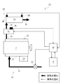
図1に示すように、ディーゼルエンジン等の内燃機関には、エンジン本体1の一方側(図中下側)に吸気系20が、他方側(図中上側)に排気系30がそれぞれ接続されている。
吸気系20には、吸気配管21、吸気マニホールド22及び燃料ポンプ23等が備えられている。吸気配管21及び吸気マニホールド22を経て、エンジン本体1のシリンダ内(吸入工程のシリンダ内)に空気を導入した後、該シリンダの圧縮工程完了時点で燃料ポンプ23から燃焼室に燃料を圧送することにより、燃焼室での混合気の自己着火燃焼に伴う膨張行程が行われるようになっている。
As shown in FIG. 1, an internal combustion engine such as a diesel engine is connected to an
The
そして、上記吸気配管21には、吸気絞り装置24が備えられている。具体的には、この吸気絞り装置24は、バタフライバルブと、このバタフライバルブを回動させて吸気配管21の流路面積を変更するアクチュエータとを備えている(共に図示省略)。尚、この弁機構としては、バタフライバルブに限らずシャッタバルブ等種々のものが適用可能である。
該吸気絞り装置24によって、前記シリンダへの空気の供給量を調節し、空気と燃料との混合比を調節している。
The
The
一方、排気系30には、排気マニホールド32及び排気配管31が備えられている。上記膨張行程後の排気行程において、シリンダから排気マニホールド32に排出された排気ガスは、排気配管31を通って、大気に放出されるようになっている。
該排気配管31には、排気ガス中に含まれるPMを捕集するためのDPF33や排気ガスを加熱するための排気ガス昇温手段34が備えられている。DPF33は、ケーシング内にフィルタ本体が収容されて成っており、該フィルタ本体は、ろ過性能を有する隔壁で区画された多数のセルを有するハニカム構造で構成されている。
On the other hand, the
The
具体的には、例えば上記の一部のセルでは一方の端部が、他のセルでは他方の端部がそれぞれ封鎖されており、セル間を排気ガスが透過する際にPMが捕集される構成となっている。該フィルタ本体を構成する材料には、耐熱性・耐酸化性・耐熱衝撃性を有するものが適しており、例えば多孔質コージェライトセラミックス、炭化珪素、アルミナ、ムライト、窒化珪素、焼結合金等が適用可能である。
また、該フィルタ本体には、白金等の酸化触媒が担持されている。そして、排気ガス温度が所定温度(例えば、約300℃、以下「再生可能温度域下限」という。)を超えた状況において、化学反応が行なわれて、即ち、PMが酸化除去されて、DPF33の機能が再生されるようになっている。
Specifically, for example, one of the above-mentioned cells is closed at one end, and the other is closed at the other, and PM is collected when exhaust gas permeates between the cells. It has a configuration. Suitable materials for the filter body include heat resistance, oxidation resistance, and thermal shock resistance, such as porous cordierite ceramics, silicon carbide, alumina, mullite, silicon nitride, and sintered alloys. Applicable.
The filter main body carries an oxidation catalyst such as platinum. In a situation where the exhaust gas temperature exceeds a predetermined temperature (for example, about 300 ° C., hereinafter referred to as “renewable temperature range lower limit”), a chemical reaction is performed, that is, PM is oxidized and removed, and the
そして、この排気系30の特徴として、図1に示すように、DPF33には音圧センサ(音圧測定手段)8F・8Rが配設されている。詳しくは、該音圧センサ8F・8Rは、マイク等によって構成されるものであり、DPF33の内部や、排気配管31内側のDPF33の上流側や下流側に配設されて、DPF33の内部や、排気配管31内側のDPF33の上流側や下流側の排気音圧(排気音の大きさ若しくは音量)を測定するものである。
As a feature of the
前記排気配管31におけるDPF33の上流側には排気ガス昇温手段(排気ガス加熱手段)34が備えられている。排気ガス昇温手段34は、電気ヒータ等によって構成されており、図示しない発電機(オルタネータ)から電力を受けて発熱し、排気配管31を流れる排気ガスを加熱可能になっている。具体的には、排気配管31を過熱することによって排気ガスを間接的に加熱する構成であっても良いし、排気配管31内部にヒータ線を配置して排気ガスを直接的に過熱する構成であっても良い。尚、この排気ガス昇温手段34としては火炎バーナーを適用しても良い。
An exhaust gas temperature raising means (exhaust gas heating means) 34 is provided upstream of the
上記排気ガス昇温手段34には、排気ガス温度を測定するための排気温度測定センサ(排気温度測定手段)36が配設されている。排気温度測定センサ36は、排気ガス昇温手段34の内部に配置されていても良いし、上記DPF33の直上流側の排気配管31内に取り付けられても良い。
該排気温度測定センサ36により、排気ガスの温度がDPF33の前記再生可能温度域下限より高いか低いかを測定することによって、前記DPF33の再生が行なわれているか否かを認識することができる。
The exhaust gas temperature raising means 34 is provided with an exhaust temperature measuring sensor (exhaust temperature measuring means) 36 for measuring the exhaust gas temperature. The exhaust
By measuring whether the exhaust gas temperature is higher or lower than the lower limit of the regenerating temperature range of the
前記音圧センサ8F・8R、排気温度測定センサ36、排気ガス昇温手段34は、演算手段10に接続されている。演算手段10は、音圧センサ8F・8Rから測定された音圧に関する信号を受け取り、該信号及び後述する記憶手段9に記憶されている音圧マップを基に、DPF33のPM堆積量を演算するものである。ここで、DPF33のPM堆積量とは、DPF33の内部に形成されている多数の前記セル(目)に付着しているPMの量を言うものである。
The
演算手段10は、DPF33のPM堆積量が予め定められた既定値以上であると判断すると、排気温度測定センサ36から排気ガス温度に関する信号を受け取って、該信号から排気ガスの温度がDPF33の前記再生可能温度域下限より高いか否かを判断する。そして、該排気ガスの温度が再生可能温度域下限より低い場合には、排気ガス昇温手段34を作動させて排気配管31を流れる排気ガスの温度を上昇させる。
When the calculation means 10 determines that the PM accumulation amount of the
前記記憶手段9は、演算手段10に接続されており、エンジン回転数やトルクや排気ガス温度に応じた音圧マップのデータが格納されている。ここで、音圧マップとは、該エンジン回転数やトルクや排気ガス温度等のエンジンの運転状況ごとに作成される、排気音圧に対するDPF33のPM堆積量の対応表である。換言すると、音圧マップとは、測定された排気音圧からDPF33のPM堆積量を求めるための変換テーブルのことを言う。
前記演算手段10は、必要に応じて、該記憶手段9から該音圧マップを呼び出して、排気音圧に関する信号からDPF33のPM堆積量を演算する。
The storage means 9 is connected to the calculation means 10 and stores sound pressure map data corresponding to the engine speed, torque and exhaust gas temperature. Here, the sound pressure map is a correspondence table of the PM accumulation amount of the
The calculation means 10 calls the sound pressure map from the storage means 9 as necessary, and calculates the PM accumulation amount of the
本実施例においては、図1に示すように、DPF33の直前(直上流)の排気配管31に、前音圧センサ(音圧測定手段)8Fを、DPF33の直後(直下流)に後音圧センサ(音圧測定手段)8Rを配設しているが、配設箇所は限定するものではない。図1に示す排気ガス浄化装置101においては、前音圧センサ8FによってDPF33直前の排気音圧(音の大きさ:db)を測定し、後音圧センサ8RによってDPF33直後の排気音圧(音の大きさ:db)を測定している。そして、該音圧の測定結果は演算手段10へと送信され、該演算手段10は、受け取った信号からDPF33の前後の音圧差を演算する。
In the present embodiment, as shown in FIG. 1, a front sound pressure sensor (sound pressure measuring means) 8F is disposed in the
図2に示すように、再生を行なうことなく使用したDPF33は、使用時間が増すとともに、DPF33上流側の前音圧センサ8Fと下流側の後音圧センサ8Rとの音圧差が大きくなってくる。これは、使用時間の経過とともに、DPF33のPM堆積量が増して、DPF33内のフィルタの目が詰まるため、DPF33前方のエンジンから伝わってくる排気音圧がDPF33によって妨げられ、DPF33前後の音圧差が拡大することが原因である。
本発明は、このような性質を利用して、排気音圧からDPF33のPM堆積量を求めることを特徴としている。
As shown in FIG. 2, the
The present invention is characterized in that the PM accumulation amount of the
そして、演算手段10は、記憶手段9から呼び出した前記音圧マップと、測定された音圧差から、DPF33のPM堆積量を演算し、該PM堆積量が予め設定された既定値以上であるか否かの判定を行なう。
そして、DPF33のPM堆積量が該既定値以上である場合には、排気温度測定センサ36によって排気ガスの温度を測定して、排気ガスの温度が前記再生可能温度域下限以下の場合は、排気ガス昇温手段34を作動させて、排気ガスの温度を上昇させる。これにより、DPF33が排気ガスによって温められ、DPF33の再生が行なわれる。
Then, the calculation means 10 calculates the PM accumulation amount of the
When the PM accumulation amount of the
このように、内燃機関の排気系30に備えられるDPF33を有した排気ガス浄化装置101・102・103であって、排気音圧を測定する1又は複数の音圧測定手段8F・8Rと、測定された該排気音圧からPM堆積量を算出する演算手段10とを具備したので、従来までの差圧を測定する場合と比べて、排気音圧の測定は測定感度が良く、応答性も速い。そのため、PM堆積量の判定を瞬時に行なうことができる。また、トランジェント運転中であっても、PM堆積量の判定が可能である。
As described above, the exhaust
また、前記DPF33の上流側に排気温度測定手段36及び排気ガス昇温手段34を配設し、前記演算手段10によって算出されたPM堆積量が予め設定された既定値よりも高く、且つ、排気温度測定手段36によって測定された排気ガス温度が該DPF33の再生可能温度域下限以下の場合に、該排気ガス昇温手段34を作動させるので、応答性に優れた排気音圧の測定結果によりPM堆積量を判定して、頻繁に排気ガス昇温手段を作動させることが可能となり、その結果燃費の悪化を防止することができる。
Further, an exhaust temperature measuring means 36 and an exhaust gas temperature raising means 34 are arranged upstream of the
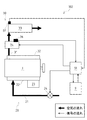
次に、排気ガス浄化装置102の第2の実施例について説明する。
図3に示すように、本実施例の排気ガス浄化装置102においては、DPF33の前部つまり上流側にのみ前音圧センサ8Fを配設する。つまり、実施例1においては、音圧センサ8F・8Fの配設位置は限定していないが、本実施例においては、DPF33の上流側にのみ前音圧センサ8Fを配設し、DPF33の上流側での排気音圧変化のみを測定することによって、DPF33のPM堆積量を認識している。
これは、DPF33のPM堆積量が増すに従って、エンジンで発生した排気音がDPF33で反射し易くなり、DPF33の上流側の排気音圧が変化する性質を利用するものである。
Next, a second embodiment of the exhaust
As shown in FIG. 3, in the exhaust
This utilizes the property that the exhaust sound generated in the engine is easily reflected by the
そして、実施例1と同様に、前記演算手段10は前記記憶手段9に接続されており、該記憶手段9には、予め実験的に測定されたDPF33のPM堆積量に応じた前音圧センサ8F用の音圧マップが記憶されている。本実施例においては、該演算手段10が、前音圧センサ8Fによって測定されたDPF33上流側の排気音圧のみから、後述する音圧マップを基にして、DPF33のPM堆積量を認識する。
As in the first embodiment, the calculation means 10 is connected to the storage means 9, and the storage means 9 includes a pre-sound pressure sensor corresponding to the PM accumulation amount of the
ここで、音圧マップとは、エンジン回転数やトルクや排気ガス温度等のエンジンの運転状況ごとに実験的に作成された、前音圧センサ8Fにて測定された排気音圧からDPF33のPM堆積量への変換テーブルである。即ち、該演算手段10は、測定時のエンジン回転数やトルク等から記憶手段9に記憶された最適な音圧マップを選択し、該音圧マップを用いて、前音圧センサ8Fにて測定された音圧からDPF33のPM堆積量を演算するのである。
参考のため、図5に、DPF33にPMが堆積していない状態においての、前後音圧センサ8F・8Rによって測定されたエンジン回転数及びトルクに応じた音圧を示す。
Here, the sound pressure map refers to the PM of the
For reference, FIG. 5 shows the sound pressure corresponding to the engine speed and torque measured by the front and rear
演算手段10は、前音圧センサ8Fで測定された排気音圧と該音圧マップからDPF33のPM堆積量を演算し、該PM堆積量が既定値以上である場合には、排気温度測定センサ36によって、排気ガス温度を測定する。そして、排気ガス温度が前記再生可能温度域下限以下の場合は、排気ガス昇温手段34を作動させて、排気ガスの温度を上昇させる。これによって、排気ガスがDPF33の温度を前記再生可能温度域にまで温め、DPF33の再生が行なわれる。
The calculating means 10 calculates the PM accumulation amount of the
このように、内燃機関の運転状況に応じた前記DPF33上流側の音圧マップを記憶する記憶手段9を具備し、前記DPF33の上流側に1の前記音圧測定手段8Fを配設し、前記演算手段10により、該音圧測定手段8Fによって測定された排気音圧と該音圧マップからPM堆積量を演算するので、1つの音圧測定手段8Fを配設することにより、DPF33のPM堆積量を認識することができるため、製造コストを低減することができる。
As described above, the storage means 9 for storing the sound pressure map on the upstream side of the
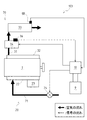
次に、排気ガス浄化装置103の第3の実施例について説明する。
図4に示すように、本実施例の排気ガス浄化装置103においては、DPF33の後部つまり下流側にのみ音圧センサ8Rを配設する。つまり、実施例1においては、音圧センサ8F・8Fの配設位置は限定していないが、本実施例においては、DPF33の下流側にのみ後音圧センサ8Rを配設し、DPF33の下流側での排気音圧変化のみを測定することによって、DPF33のPM堆積量を認識している。
これは、DPF33のPM堆積量が増すに従って、エンジンで発生した排気音がDPF33によって遮蔽され易くなるため、DPF33の下流側の排気音圧が変化する性質を利用するものである。
Next, a third embodiment of the exhaust
As shown in FIG. 4, in the exhaust
This is because the exhaust sound generated in the engine is easily shielded by the
演算手段10は記憶手段9に接続されており、該記憶手段9には、予め実験的に測定されたDPF33のPM堆積量に応じた後音圧センサ8Rの音圧マップが記憶されている。そして、演算手段10は、該音圧マップと、後音圧センサ8Rによって測定されたDPF33下流側の排気音圧のみから、DPF33のPM堆積量を演算する。
ここで、音圧マップとは、エンジン回転数やトルク等ごとに実験的によって作成された、後音圧センサ8Rにて測定された音圧からDPF33のPM堆積量への変換テーブルである。即ち、該演算手段10は、測定時のエンジン回転数やトルクから記憶手段9に記憶された最適な音圧マップを選択し、該音圧マップを用いて、後音圧センサ8Rにて測定された排気音圧からDPF33のPM堆積量を演算するのである。
The calculation means 10 is connected to the storage means 9, and the storage means 9 stores a sound pressure map of the rear
Here, the sound pressure map is a conversion table from the sound pressure measured by the rear
演算手段10は、後音圧センサ8Rで測定された排気音圧と該音圧マップからDPF33のPM堆積量を演算し、該PM堆積量が既定値以上である場合には、排気温度測定センサ36によって、排気ガス温度を測定する。そして、排気ガス温度が前記所定温度以下の場合は、排気ガス昇温手段34を作動させて、排気ガスの温度を上昇させる。これによって、排気ガスがDPF33の温度を前記再生可能温度域にまで温め、DPF33の再生が行なわれる。
The calculation means 10 calculates the PM accumulation amount of the
このように、内燃機関の運転状況に応じた前記DPF33下流側の音圧マップを記憶する記憶手段9を具備し、前記DPF33の下流側に1の前記音圧測定手段8Rを配設し、前記演算手段10により、該音圧測定手段8Rによって測定された排気音圧と該音圧マップからPM堆積量を演算するので、1つの音圧測定手段8Rを配設することにより、DPF33のPM堆積量を認識することができるため、製造コストを低減することができる。
Thus, the storage means 9 for storing the sound pressure map on the downstream side of the
次に、本発明の音圧測定で測定する周波数帯域について説明する。
DPF33周辺で測定する周波数は、前記音圧センサ8F・8Rで測定することができる周波数の全域の排気音圧を測定しても良いし、音圧センサ8F・8Rで測定することができる周波数の一部周波数帯域のみの排気音圧を測定しても良いものとする。
即ち、周波数を限定せずに、音圧センサ8F・8Rが検知した全ての排気音圧の振幅を検知しても良いし、音圧とDPF33のPM堆積量との相関係数が高い一部の周波数帯域においてのみ、排気音圧を測定する構成であっても良い。相関係数が高い該一部の周波数帯域は、エンジンの運転状況ごとに予め実験的に定めておき、該周波数帯域の範囲は記憶手段9に格納されている。
Next, the frequency band measured by the sound pressure measurement of the present invention will be described.
The frequency measured around the
That is, the amplitude of all exhaust sound pressures detected by the
図6に示すように、測定可能周波数の全域において、排気音圧を測定した場合には、測定された音圧差のばらつきが大きいが、エンジン回転数やトルクの影響を受け難い。そして、一部周波数帯域において排気音圧を測定した場合は、即ちDPF33の堆積量との相関関係が低い帯域を除いて排気音圧を測定した場合には、測定された音圧差のばらつきを小さくすることができる。
As shown in FIG. 6, when the exhaust sound pressure is measured over the entire measurable frequency range, the measured sound pressure difference varies greatly, but is hardly affected by the engine speed or torque. When the exhaust sound pressure is measured in a part of the frequency band, that is, when the exhaust sound pressure is measured except for a band having a low correlation with the amount of deposition of the
このように、音圧測定手段8F・8Rの測定可能周波数の全域、若しくは一部周波数帯域の排気音圧を測定するので、回転数の影響による補正を行なうことなく、音圧測定の精度を向上させることができる。 As described above, the exhaust sound pressure in the entire measurable frequency or a part of the frequency band of the sound pressure measuring means 8F and 8R is measured, so that the accuracy of the sound pressure measurement is improved without performing the correction due to the influence of the rotational speed. Can be made.
音圧若しくは音圧差の大きさとDPF33のPM堆積量との相関係数が高い周波数は、エンジン回転数やトルクによって異なる。一例として、回転数が2400/minの場合においての、2種類の周波数で排気音圧を測定した結果を、DPF33の使用時間と前後排気音圧差との関係として図7に示す。周波数が160Hzの排気音圧差の測定結果においては、DPF33の詰まりが進行するにつれて前後音圧センサ8F・8Rによって測定される前後音圧差は増大していくが、周波数が80Hzの排気音圧の測定結果においては、前後音圧差がほとんど変化してない。
つまり、回転数が2400/minの場合には、周波数160Hzでの排気音圧差測定によりDPF33の正確なPM堆積量を認識することができるが、周波数80Hzでの排気音圧差測定では音圧差の変化が小さいため、正確なPM堆積量を認識できない可能性がある。
The frequency at which the correlation coefficient between the sound pressure or the magnitude of the sound pressure difference and the PM deposition amount of the
That is, when the rotational speed is 2400 / min, the accurate PM accumulation amount of the
そのため、記憶手段9には、エンジン回転数やトルク等に応じた、DPF33の測定に最適な周波数帯域が記憶されている。詳しくは、記憶手段9に、エンジン回転数やトルク等に応じて、排気音圧若しくは排気音圧差とDPF33のPM堆積量との相関係数が高い周波数帯域が記憶されており、音圧センサ8F・8Rは、エンジン回転数やトルク等に応じて、複数の周波数帯域の中から相関係数が高い周波数帯域を選択して、または、組み合わせて、排気音圧若しくは排気音圧差を測定する構成となっている。そして、演算手段10は、得られた複数の排気音圧若しくは排気音圧差から、前記音圧マップに基いてPM堆積量を演算する構成となっている。
Therefore, the
このように、前記音圧測定手段8F・8Rによって、複数の周波数帯域において排気音圧を測定し、前記演算手段10が、測定された複数の周波数帯域の排気音圧からPM堆積量を算出するので、高精度な音圧測定を行なうことができる。 Thus, the sound pressure measuring means 8F and 8R measure the exhaust sound pressure in a plurality of frequency bands, and the calculation means 10 calculates the PM deposition amount from the measured exhaust sound pressures in the plurality of frequency bands. Therefore, highly accurate sound pressure measurement can be performed.
また、内燃機関の回転数に応じて、前記音圧測定手段8F・8Rにより測定する排気音圧の周波数帯域を変更するので、図7において比較した様に、高精度な音圧測定を行なうことができる。 Further, since the frequency band of the exhaust sound pressure measured by the sound pressure measuring means 8F and 8R is changed according to the rotational speed of the internal combustion engine, highly accurate sound pressure measurement is performed as compared in FIG. Can do.
また、排気ガスの温度によって、排気ガスによって伝播する排気音圧の伝播特性が異なるため、排気音圧若しくは排気音圧差とDPF33のPM堆積量の相関係数が高い周波数帯域は、排気ガスの温度によっても異なる。そのため、記憶手段9には、排気ガス温度ごとにも、音圧の大きさとDPF33のPM堆積量の相関係数が高い周波数帯域が記憶されている。
そして、排気ガス温度を前記排気温度測定センサ36によって測定し、音圧センサ8F・8R及び演算手段10は、排気ガスの温度に応じた最適な周波数帯域の排気音圧若しくは排気音圧差を測定して、DPF33のPM堆積量を演算する構成としている。
Further, since the propagation characteristics of the exhaust sound pressure propagated by the exhaust gas differ depending on the temperature of the exhaust gas, the frequency band where the correlation coefficient between the exhaust sound pressure or the exhaust sound pressure difference and the PM deposition amount of the
Then, the exhaust gas temperature is measured by the exhaust
このように、排気ガス温度に応じて、前記音圧測定手段8F・8Rにより測定する排気音圧の周波数帯域を変更するので、高精度な音圧測定を行なうことができる。 Thus, since the frequency band of the exhaust sound pressure measured by the sound pressure measuring means 8F and 8R is changed according to the exhaust gas temperature, highly accurate sound pressure measurement can be performed.
8F・8R 音圧測定手段(音圧センサ)
9 記憶手段
10 演算手段
30 排気系
33 DPF(パーティキュレートフィルタ)
34 排気ガス昇温手段
36 排気温度測定手段(排気温度測定センサ)
101・102・103 排気ガス浄化装置
8F ・ 8R Sound pressure measurement means (Sound pressure sensor)
9 Storage means 10 Calculation means 30
34 Exhaust gas temperature raising means 36 Exhaust temperature measuring means (exhaust temperature measuring sensor)
101, 102, 103 Exhaust gas purification equipment
Claims (7)
前記DPFの上流側に配設され、前記内燃機関の排気音圧を測定する音圧測定手段と、
前記内燃機関の運転状況に応じた音圧マップを記憶する記憶手段と、
前記第一の音圧測定手段により測定された排気音圧および前記記憶手段により記憶された音圧マップに基づいてPM堆積量を算出する演算手段と、
を具備することを特徴とする排気ガス浄化装置。 An exhaust gas purification device having a DPF provided in an exhaust system of an internal combustion engine,
A sound pressure measuring means disposed on the upstream side of the DPF for measuring the exhaust sound pressure of the internal combustion engine ;
Storage means for storing a sound pressure map corresponding to the operating condition of the internal combustion engine;
Calculating means for calculating the PM deposition amount based on the exhaust sound pressure measured by the first sound pressure measuring means and the sound pressure map stored by the storage means ;
An exhaust gas purification apparatus comprising:
前記演算手段は、
前記DPFの上流側に配設される音圧測定手段により測定された排気音圧と前記DPFの下流側に配設される音圧測定手段により測定された排気音圧との差である音圧差に基づいてPM堆積量を算出することを特徴とする請求項1に記載の排気ガス浄化装置。 A sound pressure measuring means disposed on the downstream side of the DPF for measuring the exhaust sound pressure of the internal combustion engine;
The computing means is
The sound pressure difference, which is the difference between the exhaust sound pressure measured by the sound pressure measuring means disposed on the upstream side of the DPF and the exhaust sound pressure measured by the sound pressure measuring means disposed on the downstream side of the DPF. The exhaust gas purification device according to claim 1, wherein the PM accumulation amount is calculated based on
前記演算手段によって算出されたPM堆積量が予め設定された既定値よりも高く、且つ、排気温度測定手段によって測定された排気ガス温度が該DPFの再生可能温度域下限以下の場合に、該排気ガス昇温手段を作動させることを特徴とする請求項1または請求項2に記載の排気ガス浄化装置。 An exhaust temperature measuring means and an exhaust gas temperature raising means are disposed upstream of the DPF,
When the PM accumulation amount calculated by the calculation means is higher than a preset default value, and the exhaust gas temperature measured by the exhaust temperature measurement means is equal to or lower than the lower limit of the regeneratable temperature range of the DPF, the exhaust gas The exhaust gas purifying device according to claim 1 or 2 , wherein the gas temperature raising means is operated.
前記演算手段が、測定された複数の周波数帯域の排気音圧からPM堆積量を算出することを特徴とする請求項1乃至請求項4の何れか一項に記載の排気ガス浄化装置。 The sound pressure measuring means measures exhaust sound pressure in a plurality of frequency bands,
The exhaust gas purification apparatus according to any one of claims 1 to 4 , wherein the calculation means calculates a PM accumulation amount from the measured exhaust sound pressures in a plurality of frequency bands.
Priority Applications (8)
| Application Number | Priority Date | Filing Date | Title |
|---|---|---|---|
| JP2005327885A JP4598655B2 (en) | 2005-11-11 | 2005-11-11 | Exhaust gas purification device |
| CA2632184A CA2632184C (en) | 2005-11-11 | 2006-10-19 | Exhaust gas purification device |
| PCT/JP2006/320867 WO2007058047A1 (en) | 2005-11-11 | 2006-10-19 | Exhaust gas purification device |
| KR1020087011928A KR100992305B1 (en) | 2005-11-11 | 2006-10-19 | Exhaust gas purification device |
| US12/093,171 US8122708B2 (en) | 2005-11-11 | 2006-10-19 | Exhaust gas purification device |
| CN2006800447574A CN101316990B (en) | 2005-11-11 | 2006-10-19 | Exhaust gas purification device |
| EP06812045A EP1950385B1 (en) | 2005-11-11 | 2006-10-19 | Exhaust gas purification device |
| AT06812045T ATE553287T1 (en) | 2005-11-11 | 2006-10-19 | EXHAUST GAS PURIFICATION DEVICE |
Applications Claiming Priority (1)
| Application Number | Priority Date | Filing Date | Title |
|---|---|---|---|
| JP2005327885A JP4598655B2 (en) | 2005-11-11 | 2005-11-11 | Exhaust gas purification device |
Publications (2)
| Publication Number | Publication Date |
|---|---|
| JP2007132306A JP2007132306A (en) | 2007-05-31 |
| JP4598655B2 true JP4598655B2 (en) | 2010-12-15 |
Family
ID=38048438
Family Applications (1)
| Application Number | Title | Priority Date | Filing Date |
|---|---|---|---|
| JP2005327885A Expired - Fee Related JP4598655B2 (en) | 2005-11-11 | 2005-11-11 | Exhaust gas purification device |
Country Status (7)
| Country | Link |
|---|---|
| US (1) | US8122708B2 (en) |
| EP (1) | EP1950385B1 (en) |
| JP (1) | JP4598655B2 (en) |
| KR (1) | KR100992305B1 (en) |
| CN (1) | CN101316990B (en) |
| CA (1) | CA2632184C (en) |
| WO (1) | WO2007058047A1 (en) |
Families Citing this family (5)
| Publication number | Priority date | Publication date | Assignee | Title |
|---|---|---|---|---|
| US20070251221A1 (en) * | 2006-04-28 | 2007-11-01 | Lueschow Kevin J | System and method for monitoring a filter |
| JP6155541B2 (en) * | 2012-01-12 | 2017-07-05 | いすゞ自動車株式会社 | Engine exhaust gas purification device |
| DE102017200539A1 (en) * | 2017-01-13 | 2018-07-19 | Robert Bosch Gmbh | Method and device for loading diagnosis of a particle filter |
| EP3650773A4 (en) * | 2017-07-06 | 2021-03-10 | Kondoh Industries, Ltd. | Device for measuring clogging of filter in air-conditioning equipment, and air-conditioning equipment |
| EP4074403A1 (en) * | 2021-04-14 | 2022-10-19 | Carrier Corporation | Filter monitoring using differential acoustic attenuation |
Citations (4)
| Publication number | Priority date | Publication date | Assignee | Title |
|---|---|---|---|---|
| GB2017916A (en) * | 1978-04-04 | 1979-10-10 | Benjamins L | A method and apparatus for determining the thickness of the filter- cake on a filter element of a filter assembly. |
| JPH08121150A (en) * | 1994-10-27 | 1996-05-14 | Isuzu Ceramics Kenkyusho:Kk | Control device for diesel particulate filter |
| JP2001518380A (en) * | 1997-09-30 | 2001-10-16 | ポール・コーポレーション | Apparatus and method for locating a defective filter element among a plurality of filter elements |
| WO2004026434A1 (en) * | 2002-09-12 | 2004-04-01 | Robert Bosch Gmbh | Device and method for determining the state of a particle filter |
Family Cites Families (9)
| Publication number | Priority date | Publication date | Assignee | Title |
|---|---|---|---|---|
| JP3246151B2 (en) | 1993-12-25 | 2002-01-15 | 株式会社デンソー | Diesel engine exhaust purification system |
| JP3598961B2 (en) | 2000-09-26 | 2004-12-08 | 日産自動車株式会社 | Exhaust gas purification device for internal combustion engine |
| JP3812362B2 (en) * | 2001-04-19 | 2006-08-23 | 日産自動車株式会社 | Exhaust gas purification device for internal combustion engine |
| US6964694B2 (en) * | 2002-04-29 | 2005-11-15 | Avl North America Inc. | Diesel particulate filter monitoring using acoustic sensing |
| US6871489B2 (en) * | 2003-04-16 | 2005-03-29 | Arvin Technologies, Inc. | Thermal management of exhaust systems |
| JP4120523B2 (en) * | 2003-07-31 | 2008-07-16 | 日産自動車株式会社 | Exhaust gas recirculation control device for internal combustion engine |
| JP4320621B2 (en) * | 2003-08-25 | 2009-08-26 | 株式会社デンソー | Exhaust gas purification device for internal combustion engine |
| US20080018442A1 (en) * | 2005-07-26 | 2008-01-24 | Knitt Andrew A | Particulate loading monitoring system |
| US7412889B2 (en) * | 2006-02-28 | 2008-08-19 | Caterpillar Inc. | System and method for monitoring a filter |
-
2005
- 2005-11-11 JP JP2005327885A patent/JP4598655B2/en not_active Expired - Fee Related
-
2006
- 2006-10-19 EP EP06812045A patent/EP1950385B1/en not_active Not-in-force
- 2006-10-19 WO PCT/JP2006/320867 patent/WO2007058047A1/en active Application Filing
- 2006-10-19 KR KR1020087011928A patent/KR100992305B1/en not_active IP Right Cessation
- 2006-10-19 CN CN2006800447574A patent/CN101316990B/en not_active Expired - Fee Related
- 2006-10-19 CA CA2632184A patent/CA2632184C/en not_active Expired - Fee Related
- 2006-10-19 US US12/093,171 patent/US8122708B2/en not_active Expired - Fee Related
Patent Citations (4)
| Publication number | Priority date | Publication date | Assignee | Title |
|---|---|---|---|---|
| GB2017916A (en) * | 1978-04-04 | 1979-10-10 | Benjamins L | A method and apparatus for determining the thickness of the filter- cake on a filter element of a filter assembly. |
| JPH08121150A (en) * | 1994-10-27 | 1996-05-14 | Isuzu Ceramics Kenkyusho:Kk | Control device for diesel particulate filter |
| JP2001518380A (en) * | 1997-09-30 | 2001-10-16 | ポール・コーポレーション | Apparatus and method for locating a defective filter element among a plurality of filter elements |
| WO2004026434A1 (en) * | 2002-09-12 | 2004-04-01 | Robert Bosch Gmbh | Device and method for determining the state of a particle filter |
Also Published As
| Publication number | Publication date |
|---|---|
| CN101316990A (en) | 2008-12-03 |
| US20090151325A1 (en) | 2009-06-18 |
| CA2632184C (en) | 2011-04-12 |
| EP1950385A1 (en) | 2008-07-30 |
| EP1950385B1 (en) | 2012-04-11 |
| CN101316990B (en) | 2012-04-25 |
| KR100992305B1 (en) | 2010-11-05 |
| JP2007132306A (en) | 2007-05-31 |
| WO2007058047A1 (en) | 2007-05-24 |
| KR20080081900A (en) | 2008-09-10 |
| US8122708B2 (en) | 2012-02-28 |
| EP1950385A4 (en) | 2011-01-05 |
| CA2632184A1 (en) | 2007-05-24 |
Similar Documents
| Publication | Publication Date | Title |
|---|---|---|
| JP4445314B2 (en) | Diagnostic system and method for pressure sensor by computer | |
| JP4403944B2 (en) | Exhaust gas purification device for internal combustion engine | |
| US6735941B2 (en) | Exhaust gas purification system having particulate filter | |
| JP4042476B2 (en) | Exhaust gas purification device for internal combustion engine | |
| JP4506539B2 (en) | Exhaust gas purification device for internal combustion engine | |
| KR100899967B1 (en) | Exhaust gas purifying apparatus | |
| EP1529931A1 (en) | Filter control device | |
| EP1528229A1 (en) | Filter control method and device | |
| JP2004245123A (en) | Exhaust emission control device of internal combustion engine | |
| US20040172933A1 (en) | Internal combustion engine exhaust gas purification system | |
| JP2008101606A (en) | Particulate detection sensor | |
| JP2005226519A (en) | Abnormality detection device for emission control device of internal combustion engine | |
| JP4598655B2 (en) | Exhaust gas purification device | |
| JPWO2004036002A1 (en) | Exhaust gas purification device for internal combustion engine | |
| JP2004036454A (en) | Exhaust emission control device of engine for vehicle | |
| JP4537232B2 (en) | Control method of fuel injection amount | |
| JP3918619B2 (en) | Exhaust gas purification device for internal combustion engine | |
| JP2004132358A (en) | Filter control device | |
| JP2016130456A (en) | Internal combustion engine control unit | |
| JP4534959B2 (en) | Exhaust gas purification device for internal combustion engine | |
| JP2007332905A (en) | Temperature measuring device of internal combustion engine | |
| JP3782694B2 (en) | Exhaust purification device | |
| JP7211192B2 (en) | Exhaust purification device | |
| JP6024379B2 (en) | Exhaust purification device | |
| JP2012177374A (en) | Exhaust emission control device |
Legal Events
| Date | Code | Title | Description |
|---|---|---|---|
| A621 | Written request for application examination |
Free format text: JAPANESE INTERMEDIATE CODE: A621 Effective date: 20071128 |
|
| A131 | Notification of reasons for refusal |
Free format text: JAPANESE INTERMEDIATE CODE: A131 Effective date: 20100615 |
|
| A521 | Written amendment |
Free format text: JAPANESE INTERMEDIATE CODE: A523 Effective date: 20100810 |
|
| TRDD | Decision of grant or rejection written | ||
| A01 | Written decision to grant a patent or to grant a registration (utility model) |
Free format text: JAPANESE INTERMEDIATE CODE: A01 Effective date: 20100914 |
|
| A01 | Written decision to grant a patent or to grant a registration (utility model) |
Free format text: JAPANESE INTERMEDIATE CODE: A01 |
|
| A61 | First payment of annual fees (during grant procedure) |
Free format text: JAPANESE INTERMEDIATE CODE: A61 Effective date: 20100924 |
|
| R150 | Certificate of patent or registration of utility model |
Free format text: JAPANESE INTERMEDIATE CODE: R150 |
|
| FPAY | Renewal fee payment (event date is renewal date of database) |
Free format text: PAYMENT UNTIL: 20131001 Year of fee payment: 3 |
|
| FPAY | Renewal fee payment (event date is renewal date of database) |
Free format text: PAYMENT UNTIL: 20131001 Year of fee payment: 3 |
|
| S531 | Written request for registration of change of domicile |
Free format text: JAPANESE INTERMEDIATE CODE: R313531 |
|
| FPAY | Renewal fee payment (event date is renewal date of database) |
Free format text: PAYMENT UNTIL: 20131001 Year of fee payment: 3 |
|
| R350 | Written notification of registration of transfer |
Free format text: JAPANESE INTERMEDIATE CODE: R350 |
|
| FPAY | Renewal fee payment (event date is renewal date of database) |
Free format text: PAYMENT UNTIL: 20141001 Year of fee payment: 4 |
|
| LAPS | Cancellation because of no payment of annual fees |