JP4537232B2 - Control method of fuel injection amount - Google Patents
Control method of fuel injection amount Download PDFInfo
- Publication number
- JP4537232B2 JP4537232B2 JP2005068655A JP2005068655A JP4537232B2 JP 4537232 B2 JP4537232 B2 JP 4537232B2 JP 2005068655 A JP2005068655 A JP 2005068655A JP 2005068655 A JP2005068655 A JP 2005068655A JP 4537232 B2 JP4537232 B2 JP 4537232B2
- Authority
- JP
- Japan
- Prior art keywords
- soot
- fuel injection
- amount
- injection amount
- engine
- Prior art date
- Legal status (The legal status is an assumption and is not a legal conclusion. Google has not performed a legal analysis and makes no representation as to the accuracy of the status listed.)
- Expired - Fee Related
Links
Images


Description
本発明は、燃料噴射量の制御方法、燃料噴射量の制御システム及び燃料噴射量の制御プログラムに関する。さらに詳しくは、ディーゼルエンジン等から排出される排出スート量を減少させること及び燃費を向上させることが可能な燃料噴射量の制御方法、燃料噴射量の制御システム及び燃料噴射量の制御プログラムに関する。 The present invention relates to a fuel injection amount control method, a fuel injection amount control system, and a fuel injection amount control program. More specifically, the present invention relates to a fuel injection amount control method, a fuel injection amount control system, and a fuel injection amount control program that can reduce the amount of soot discharged from a diesel engine or the like and improve fuel efficiency.
ディーゼルエンジンは燃費と耐久性に優れた動力源であり、そのエンジンから排出されるHC及びCOがガソリンエンジンに比べて少ないため、近年問題となっている地球温暖化に対しては好ましい内燃機関である。しかしながら、ディーゼルエンジンにおいては、その混合気燃焼時に発生するNOx及び排気微粒子(スート)がガソリンエンジンに比べて多く、このNOx及びスートを排出ガスから低減させることが喫緊の課題となっている。この点、ディーゼルエンジンからの排気ガスの流路中に酸化触媒を設け、さらにその下流側に、セラミックの多孔質壁をフィルタ素子とするDPFを設けておき、ディーゼルエンジンから排出された排気ガス中のNO、CO、HC等を酸化触媒によって酸化し、酸化後の排気ガスがDPFの多孔質壁を通過する際に、その気孔(ポア)部分において排気ガスに含まれるスートを捕集する排気ガス浄化システムが知られている。 Diesel engine is a power source with excellent fuel efficiency and durability, and HC and CO emitted from the engine is less than gasoline engine, so it is a preferable internal combustion engine against global warming, which has become a problem in recent years. is there. However, in a diesel engine, there are more NOx and exhaust particulates (soot) generated during the combustion of the air-fuel mixture than in a gasoline engine, and it is an urgent issue to reduce this NOx and soot from exhaust gas. In this regard, an oxidation catalyst is provided in the exhaust gas flow path from the diesel engine, and further, a DPF having a ceramic porous wall as a filter element is provided on the downstream side thereof, in the exhaust gas discharged from the diesel engine. NOx, CO, HC, etc. are oxidized by an oxidation catalyst, and when the oxidized exhaust gas passes through the porous wall of the DPF, the exhaust gas collects the soot contained in the exhaust gas at the pores. Purification systems are known.
この排気ガス浄化システムにおいては、フィルタの壁内の気孔部分及び壁表面においてスートを捕集し、捕集されたスートを燃焼除去(再生)する際に、捕集されたスート量が多すぎると燃焼時の過熱によってフィルタを破損させることがあるため、フィルタにより捕集することができるスート量には限界があった。この捕集限界スート量を検出する方法としては、DPFの上流側及び下流側における排気ガスの圧力差(「圧力損失」、略して「圧損」ということがある)及び排気ガス温度をそれぞれ検出してフィルタ内に堆積しているスート量を予測して、その予測値に基づいてDPFが捕集限界であることを検出する方法(特許文献1参照)、及び燃料噴射量、エンジン回転数、排気ガス温度等のマッピングから排出スート量を予測し、その積算量に基づいてDPFが捕集限界であることを検出する方法(特許文献2参照)等が開示されている。
しかし、特許文献1に開示されているような、DPFの上流側と下流側の圧力差からDPFが捕集限界であることを検出する方法では、DPF再生前と再生後とで堆積スート量と圧損との関係がヒステリシスを持ち、そのために圧損から予測されるスート量の精度が悪いという不都合があった。また、特許文献2に開示されているような、燃料噴射量、エンジン回転数、排気ガス温度等のマッピングから排出スート量を予測してDPFが捕集限界であることを検出する方法では、各燃料噴射器の個体バラツキや経時的な変動により、指示燃料噴射量と実燃料噴射量の誤差が生じるために、排出スート量の予測の精度が悪くなってしまうという不都合があった。 However, in the method for detecting that the DPF is at the collection limit from the pressure difference between the upstream side and the downstream side of the DPF as disclosed in Patent Document 1, the amount of accumulated soot before and after the DPF regeneration The relationship with the pressure loss has a hysteresis, which causes a disadvantage that the accuracy of the soot amount predicted from the pressure loss is poor. Further, as disclosed in Patent Document 2, the method of predicting the exhaust soot amount from the mapping of the fuel injection amount, the engine speed, the exhaust gas temperature, etc., and detecting that the DPF is at the collection limit, There is an inconvenience that the accuracy of the estimation of the exhaust soot amount deteriorates because an error between the commanded fuel injection amount and the actual fuel injection amount occurs due to individual variations in fuel injectors and fluctuations with time.
上述の不都合を解消するために、従来は再生させる予測スート量を少なくしてDPFの再生を行っていたが、再生時のスート堆積量を少なくすると再生インターバルを短くすることになり、燃費を悪化させるという問題があるとともに、スート堆積量が少ない時点において、DPF内の位置における付着スート量のバラツキから、完全にスートを再生することができない部分を残した状態のままでスートの再生を終了してしまうという問題もあった。 In order to eliminate the inconveniences described above, the DPF regeneration was conventionally performed by reducing the predicted soot amount to be regenerated. However, if the soot accumulation amount at the time of regeneration is decreased, the regeneration interval is shortened and the fuel consumption is deteriorated. When the soot accumulation amount is small, the soot regeneration is finished while leaving a portion where the soot cannot be completely regenerated due to the variation in the amount of adhering soot at the position in the DPF. There was also a problem of end up.
本発明は上述の問題に鑑みてなされたものであり、ディーゼルエンジン等から排出されるスート量の予測精度を高めてエンジンの実燃料噴射量を最適に制御することによって、排出スート量を減少させることが可能であるとともに、燃焼効率の向上に伴って燃費を向上させることが可能な燃料噴射量の制御方法、燃料噴射量の制御システム及び燃料噴射量の制御プログラムを提供することを目的とする。 The present invention has been made in view of the above-described problems, and reduces the soot amount by increasing the accuracy of predicting the soot amount discharged from a diesel engine or the like and optimally controlling the actual fuel injection amount of the engine. An object of the present invention is to provide a fuel injection amount control method, a fuel injection amount control system, and a fuel injection amount control program capable of improving fuel efficiency as combustion efficiency is improved. .
上記目的を達成するため、本発明によれば、以下の燃料噴射量の制御方法、燃料噴射量の制御システム及び燃料噴射量の制御プログラムが提供される。 To achieve the above object, according to the present invention, the following fuel injection amount control method, fuel injection amount control system, and fuel injection amount control program are provided.
[1]エンジンの燃料噴射量を、初期設定値から、走行中における所定の条件に基づき補正することによって制御する燃料噴射量の制御方法であって、スートセンサを用いて、前記エンジンから排出される排気ガスに含まれるスート排出量を測定する第1のステップと、少なくとも前記エンジンの回転数、前記排気ガスの温度及び前記エンジンの初期設定燃料噴射量を含むスート排出量推定用要素に基づいて、推定スート排出量を算定する第2のステップと、前記スート排出量及び前記推定スート排出量に基づいて設定される誤差判定基準値と、誤差閾値とを比較する第3のステップと、前記誤差判定基準値が、前記誤差閾値以上である場合、少なくとも前記スート排出量、前記エンジンの回転数及び前記排気ガスの温度を含むエンジンの実際の燃料噴射量算出要素に基づいて前記エンジンの実際の燃料噴射量を算定し、前記エンジンの初期設定燃料噴射量を前記実際の燃料噴射量に補正してから、前記第1のステップに戻るか、又は前記誤差判定基準値が、前記誤差閾値未満である場合、前記エンジンの初期設定燃料噴射量を補正することなくそのまま前記第1のステップに戻る第4のステップと、を含むことを特徴とする燃料噴射量の制御方法。 [1] A fuel injection amount control method for controlling a fuel injection amount of an engine by correcting the fuel injection amount from an initial set value based on a predetermined condition during traveling, and is discharged from the engine using a soot sensor Based on the first step of measuring the soot emission amount contained in the exhaust gas, and the soot emission amount estimation element including at least the engine speed, the exhaust gas temperature, and the initial fuel injection amount of the engine, A second step of calculating an estimated soot emission amount, a third step of comparing an error threshold value with an error determination reference value set based on the soot emission amount and the estimated soot emission amount, and the error determination When the reference value is equal to or greater than the error threshold, the engine performance including at least the soot emission amount, the engine speed, and the exhaust gas temperature is included. Whether the actual fuel injection amount of the engine is calculated based on the fuel injection amount calculation element of the engine, the initial fuel injection amount of the engine is corrected to the actual fuel injection amount, and then the process returns to the first step. Or a fourth step of returning to the first step without correcting the initial fuel injection amount of the engine when the error determination reference value is less than the error threshold. Control method of fuel injection amount.
[2]前記誤差判定基準値として、前記推定スート排出量と、前記スート排出量との間における下記式(1)に示す関係から算出される値を用いる前記[1]に記載の燃料噴射量の制御方法。
C=│1−(B/A)│………(1)
(上記式(1)中、Aはスート排出量、Bは推定スート排出量、Cは誤差判定基準値をそれぞれ示す。)
[2] The fuel injection amount according to [1], wherein a value calculated from the relationship shown in the following formula (1) between the estimated soot discharge amount and the soot discharge amount is used as the error determination reference value. Control method.
C = │1- (B / A) │ …… (1)
(In the above formula (1), A represents the soot discharge amount, B represents the estimated soot discharge amount, and C represents the error determination reference value.)
[3]前記スートセンサとして、瞬時スート濃度測定タイプ又は累積スート量測定タイプのものを用いる前記[1]又は[2]に記載の燃料噴射量の制御方法。 [3] The fuel injection amount control method according to [1] or [2], wherein an instantaneous soot concentration measurement type or cumulative soot amount measurement type is used as the soot sensor.
[4]前記瞬時スート濃度測定タイプのスートセンサとして、前記スートの瞬時における、電荷量、又は光の透過量若しくは散乱量を測定するものを用いる前記[3]に記載の燃料噴射量の制御方法。 [4] The method for controlling the fuel injection amount according to [3], wherein the soot sensor of the instantaneous soot concentration measurement type uses a sensor that measures the amount of charge, light transmission, or scattering at the instant of the soot.
[5]前記累積スート量測定タイプのスートセンサとして、前記スートの測定までの累積における、抵抗変化、温度変化、又は圧電/電歪材料の共振周波数変化を測定するものを用いる前記[3]に記載の燃料噴射量の制御方法。 [5] As described in the above [3], the soot sensor of the cumulative soot amount measurement type uses a sensor that measures a resistance change, a temperature change, or a resonance frequency change of a piezoelectric / electrostrictive material in the accumulation until the measurement of the soot. Control method of fuel injection amount.
[6]エンジンの燃料噴射量を、初期設定値から、走行中における所定の条件に基づき補正することによって制御することが可能な燃料噴射量の制御システムであって、スートセンサを有し、前記スートセンサによって、前記エンジンから排出される排気ガスに含まれるスート排出量を測定することが可能なスート排出量測定手段と、少なくとも前記エンジンの回転数、前記排気ガスの温度及び前記エンジンの初期設定燃料噴射量を含むスート排出量推定用要素に基づいて推定される推定スート排出量を算定することが可能な推定スート排出量算定手段と、前記スート排出量及び前記推定スート排出量に基づいて設定される誤差判定基準値と、誤差閾値とを比較することが可能な誤差判定基準値・誤差閾値比較手段と、前記誤差判定基準値が、前記誤差閾値以上である場合、少なくとも前記スート排出量、前記エンジンの回転数及び前記排気ガスの温度を含むエンジンの実際の燃料噴射量算出要素に基づいて前記エンジンの実際の燃料噴射量を算定し、前記エンジンの初期設定燃料噴射量を前記実際の燃料噴射量に補正してから、前記スート排出量測定手段による前記スート排出量の測定に戻るか、又は前記誤差判定基準値が、前記誤差閾値未満である場合、前記エンジンの初期設定燃料噴射量を補正することなくそのまま前記スート排出量測定手段による前記スート排出量の測定に戻ることが可能な燃料噴射量補正手段と、を備えたことを特徴とする燃料噴射量の制御システム。 [6] A fuel injection amount control system capable of controlling the fuel injection amount of the engine by correcting the fuel injection amount from an initial setting value based on a predetermined condition during traveling, the soot sensor having a soot sensor, Means for measuring the soot emission amount contained in the exhaust gas discharged from the engine, at least the engine speed, the temperature of the exhaust gas, and the initial setting fuel injection of the engine An estimated soot emission calculating means capable of calculating an estimated soot emission estimated based on a soot emission estimation element including the amount, and the soot emission and the estimated soot emission are set based on An error determination reference value / error threshold comparison means capable of comparing an error determination reference value and an error threshold, and the error determination reference value If the error threshold value is greater than or equal to the error threshold, the actual fuel injection amount of the engine is calculated based on an actual fuel injection amount calculation factor of the engine including at least the soot emission amount, the engine speed, and the exhaust gas temperature. The initial fuel injection amount of the engine is corrected to the actual fuel injection amount and then the soot discharge measuring means returns to the measurement of the soot discharge amount, or the error determination reference value is the error threshold value. A fuel injection amount correcting means capable of returning to the measurement of the soot discharge amount by the soot discharge amount measuring means without correcting the initial set fuel injection amount of the engine. A fuel injection amount control system.
[7]前記誤差判定基準値が、前記推定スート排出量と、前記スート排出量との間における下記式(1)に示す関係から算出される値である前記[6]に記載の燃料噴射量の制御システム。
C=│1−(B/A)│………(1)
(上記式(1)中、Aはスート排出量、Bは推定スート排出量、Cは誤差判定基準値をそれぞれ示す。)
[7] The fuel injection amount according to [6], wherein the error determination reference value is a value calculated from a relationship represented by the following expression (1) between the estimated soot discharge amount and the soot discharge amount. Control system.
C = │1- (B / A) │ …… (1)
(In the above formula (1), A represents the soot discharge amount, B represents the estimated soot discharge amount, and C represents the error determination reference value.)
[8]前記スートセンサが、瞬時スート濃度測定タイプ又は累積スート量測定タイプのものである前記[6]又は[7]に記載の燃料噴射量の制御システム。 [8] The fuel injection amount control system according to [6] or [7], wherein the soot sensor is of an instantaneous soot concentration measurement type or an accumulated soot amount measurement type.
[9]前記瞬時スート濃度測定タイプのスートセンサが、前記スートの瞬時における、電荷量、又は光の透過量若しくは散乱量を測定するものである前記[8]に記載の燃料噴射量の制御システム。 [9] The fuel injection amount control system according to [8], wherein the soot sensor of the instantaneous soot concentration measurement type measures a charge amount, a light transmission amount or a scattering amount at an instant of the soot.
[10]前記累積スート量測定タイプのスートセンサが、前記スートの測定までの累積における、抵抗変化、温度変化、又は圧電/電歪材料の共振周波数変化を測定するものである前記[8]に記載の燃料噴射量の制御システム。 [10] The above-mentioned [8], wherein the soot sensor of the cumulative soot measurement type measures a resistance change, a temperature change, or a resonance frequency change of the piezoelectric / electrostrictive material in the accumulation until the measurement of the soot. Fuel injection amount control system.
[11]エンジンの燃料噴射量を、初期設定値から、走行中における所定の条件に基づき補正することによって制御するための、コンピュータが読み込み可能なエンジンの燃料噴射量の制御プログラムであって、
前記コンピュータを、下記(1)〜(4)の手段として機能させることが可能なことを特徴とする燃料噴射量の制御プログラム。
(1)スートセンサに、前記エンジンから排出される排気ガスに含まれるスート排出量を測定させることが可能なスート排出量測定手段、
(2)少なくとも前記エンジンの回転数、前記排気ガスの温度及び前記エンジンの初期設定燃料噴射量を含むスート排出量推定用要素に基づいて推定される推定スート排出量を算定することが可能な推定スート排出量算定手段、
(3)前記スート排出量及び前記推定スート排出量に基づいて設定される誤差判定基準値と、誤差閾値とを比較することが可能な誤差判定基準値・誤差閾値比較手段、
(4)前記誤差判定基準値が、前記誤差閾値以上である場合、少なくとも前記スート排出量、前記エンジンの回転数及び前記排気ガスの温度を含むエンジンの実際の燃料噴射量算出要素に基づいて前記エンジンの実際の燃料噴射量を算定し、前記エンジンの初期設定燃料噴射量を前記実際の燃料噴射量に補正してから、前記スート排出量測定手段による前記スート排出量の測定に戻るか、又は前記誤差判定基準値が、前記誤差閾値未満である場合、前記エンジンの初期設定燃料噴射量を補正することなくそのまま前記スート排出量測定手段による前記スート排出量の測定に戻ることが可能な燃料噴射量補正手段。
[11] A computer-readable engine fuel injection amount control program for controlling the fuel injection amount of the engine by correcting the fuel injection amount from an initial setting value based on a predetermined condition during traveling,
A fuel injection amount control program capable of causing the computer to function as the following means (1) to (4).
(1) Soot emission measuring means capable of causing the soot sensor to measure the soot emission contained in the exhaust gas exhausted from the engine;
(2) Estimate capable of calculating an estimated soot emission amount estimated based on a soot emission amount estimation element including at least the engine speed, the exhaust gas temperature, and the initial fuel injection amount of the engine Soot emission calculation means,
(3) an error determination reference value / error threshold comparison means capable of comparing an error determination reference value set based on the soot discharge amount and the estimated soot discharge amount with an error threshold;
(4) When the error determination reference value is greater than or equal to the error threshold, the actual fuel injection amount calculation factor of the engine including at least the soot emission amount, the engine speed, and the exhaust gas temperature is used. Calculating the actual fuel injection amount of the engine and correcting the initial fuel injection amount of the engine to the actual fuel injection amount, and then returning to the measurement of the soot discharge amount by the soot discharge measuring means, or When the error determination reference value is less than the error threshold, the fuel injection that can return to the measurement of the soot discharge amount by the soot discharge amount measuring means without correcting the initial fuel injection amount of the engine Amount correction means.
[12]前記誤差判定基準値が、前記推定スート排出量と、前記スート排出量との間における下記式(1)に示す関係から算出される値である前記[11]に記載の燃料噴射量の制御プログラム。
C=│1−(B/A)│………(1)
(上記式(1)中、Aはスート排出量、Bは推定スート排出量、Cは誤差判定基準値をそれぞれ示す。)
[12] The fuel injection amount according to [11], wherein the error determination reference value is a value calculated from a relationship represented by the following formula (1) between the estimated soot discharge amount and the soot discharge amount: Control program.
C = │1- (B / A) │ …… (1)
(In the above formula (1), A represents the soot discharge amount, B represents the estimated soot discharge amount, and C represents the error determination reference value.)
[13]前記スートセンサが、瞬時スート濃度測定タイプ又は累積スート量測定タイプのものである前記[11]又は[12]に記載の燃料噴射量の制御プログラム。 [13] The fuel injection amount control program according to [11] or [12], wherein the soot sensor is of an instantaneous soot concentration measurement type or an accumulated soot amount measurement type.
[14]前記瞬時スート濃度測定タイプのスートセンサが、前記スートの瞬時における、電荷量、又は光の透過量若しくは散乱量を測定するものである前記[13]に記載の燃料噴射量の制御プログラム。 [14] The fuel injection amount control program according to [13], wherein the soot sensor of the instantaneous soot concentration measurement type measures a charge amount, a light transmission amount, or a scattering amount at an instant of the soot.
[15]前記累積スート量測定タイプのスートセンサが、前記スートの測定までの累積における、抵抗変化、温度変化、又は圧電/電歪材料の共振周波数変化を測定するものである前記[13]に記載の燃料噴射量の制御プログラム。 [15] The above-described [13], wherein the soot sensor of the cumulative soot measurement type measures a resistance change, a temperature change, or a resonance frequency change of the piezoelectric / electrostrictive material in the accumulation until the measurement of the soot. Control program for fuel injection.
なお、本発明における「プログラム」とは、コンピュータによる処理に適した命令の順番付けられた列からなるものを意味し、具体的には、コンピュータのHD(Hard Disk)、CD−RW等にインストールされているもの;CD−ROM、DVD、FD、半導体メモリ、コンピュータのHDD等の各種記録媒体に記録されているもの;インターネット等の外部ネットワークを介して配信されるもの等を意味する。 The “program” in the present invention means an ordered sequence of instructions suitable for processing by a computer. Specifically, it is installed in a computer HD (Hard Disk), CD-RW or the like. Means recorded on various recording media such as CD-ROM, DVD, FD, semiconductor memory, and computer HDD; and distributed via an external network such as the Internet.
以上説明したように、本発明によって、ディーゼルエンジン等から排出されるスート量の予測精度を高めてエンジンの実燃料噴射量を最適に制御することによって、排出スート量を減少させることが可能であるとともに、燃焼効率の向上に伴って燃費を向上させることが可能な燃料噴射量の制御方法、燃料噴射量の制御システム及び燃料噴射量の制御プログラムが提供される。 As described above, according to the present invention, it is possible to reduce the exhaust soot amount by improving the prediction accuracy of the soot amount discharged from a diesel engine or the like and optimally controlling the actual fuel injection amount of the engine. In addition, a fuel injection amount control method, a fuel injection amount control system, and a fuel injection amount control program capable of improving fuel efficiency as combustion efficiency is improved are provided.
以下、本発明を実施するための最良の形態を図面を参照しつつ具体的に説明する。 Hereinafter, the best mode for carrying out the present invention will be specifically described with reference to the drawings.
以下、本発明を実施するための最良の形態を具体的に説明する。本発明の燃料噴射量の制御方法は、上述のように、エンジンの燃料噴射量を、初期設定値から、走行中における所定の条件に基づき補正することによって制御する燃料噴射量の制御方法であり、第1〜第4のステップを含むことを特徴とする。以下各ステップごとに具体的に説明する。なお、ここでは、本発明として燃料噴射量の制御方法を中心として説明するが、燃料噴射量の制御システム及び燃料噴射量の制御プログラムの場合も基本的に同様である。 The best mode for carrying out the present invention will be specifically described below. The fuel injection amount control method of the present invention is a fuel injection amount control method that controls the fuel injection amount of the engine by correcting the fuel injection amount of the engine from an initial set value based on a predetermined condition during traveling as described above. First to fourth steps are included. Hereinafter, each step will be described in detail. Here, the fuel injection amount control method will be mainly described as the present invention, but the fuel injection amount control system and the fuel injection amount control program are basically the same.
(第1のステップ)
第1のステップは、スートセンサを用いて、エンジンから排出される排気ガスに含まれるスート排出量を測定するステップである。
(First step)
The first step is a step of measuring the soot discharge amount contained in the exhaust gas discharged from the engine using a soot sensor.
第1のステップに用いられるスートセンサとしては特に制限はないが、例えば、瞬時スート濃度測定タイプ又は累積スート量測定タイプのものを挙げることができる。瞬時スート濃度測定タイプのスートセンサとしては、例えば、スートの瞬時における、電荷量、又は光の透過量若しくは散乱量を測定するものを挙げることができる。また、累積スート量測定タイプのスートセンサとして、例えば、スートの測定までの累積における、抵抗変化、温度変化、又は圧電/電歪材料の共振周波数変化を測定するものを挙げることができる。このようなスートセンサを用いて、スート排出量を測定する方法としては、例えば、瞬時スート濃度測定タイプの場合、スートセンサ出力値をそのままスート排出量とすることを挙げることができ、また、累積スート量測定タイプの場合、今回測定した累積スート量から前回第1のステップで測定した累積スート量を減算することで、今回のスート排出量を求めるようにすることを挙げることができる。 Although there is no restriction | limiting in particular as a soot sensor used for a 1st step, For example, the thing of an instantaneous soot density | concentration measurement type or a cumulative soot amount measurement type can be mentioned. Examples of the soot sensor of the instantaneous soot concentration measurement type include a sensor that measures the amount of charge, the amount of transmitted light or the amount of scattering at the moment of soot. Further, examples of the soot sensor of the cumulative soot measurement type include a sensor that measures a resistance change, a temperature change, or a resonance frequency change of a piezoelectric / electrostrictive material in the accumulation until the soot measurement. As a method of measuring the soot discharge amount using such a soot sensor, for example, in the case of the instantaneous soot concentration measurement type, the soot sensor output value can be directly used as the soot discharge amount, and the cumulative soot discharge amount can be mentioned. In the case of the measurement type, the current soot discharge amount can be obtained by subtracting the cumulative soot amount measured in the first step from the cumulative soot amount measured this time.
(第2のステップ)
第2のステップは、少なくともエンジンの回転数、排気ガスの温度及びエンジンの初期設定燃料噴射量を含むスート排出量推定用要素に基づいて、推定スート排出量を算定するステップである。
(Second step)
The second step is a step of calculating an estimated soot emission amount based on at least a soot emission amount estimation element including an engine speed, an exhaust gas temperature, and an engine initial fuel injection amount.
スート排出量推定用要素(マッピングによるスート排出量を推定するための要素)としては、エンジンの回転数、排気ガスの温度、エンジンの初期設定燃料噴射量、アクセル開度等を挙げることができる。中でも、エンジンの回転数、排気ガスの温度及びエンジンの初期設定燃料噴射量が、スート排出量との相関が密接であり、少なくともこの3つの要素を含むものとする。スート排出量推定用要素に基づいて、推定スート排出量を算定する方法としては、エンジンの回転数の場合、例えば、特開平5−18228号公報のようにすること、排気ガスの温度の場合、例えば、特開平7−139334号公報のようにすること、初期設定燃料噴射量の場合、例えば、トヨタ技術公開集(2004年5月31日発行、発行番号15776)第4実施例のようにすることを挙げることができる。 Examples of the soot emission amount estimation element (an element for estimating the soot emission amount by mapping) include engine speed, exhaust gas temperature, engine initial fuel injection amount, accelerator opening, and the like. In particular, the engine speed, the exhaust gas temperature, and the initial fuel injection amount of the engine are closely correlated with the soot emission amount, and include at least these three elements. As a method for calculating the estimated soot emission amount based on the soot emission estimation element, in the case of the engine speed, for example, as in JP-A-5-18228, in the case of the exhaust gas temperature, For example, as in JP-A-7-139334, in the case of the initial fuel injection amount, for example, as in the fourth embodiment of the Toyota Technical Publication (issued May 31, 2004, issue number 15776) Can be mentioned.
(第3のステップ)
第3のステップは、スート排出量及び推定スート排出量に基づいて設定される誤差判定基準値と、誤差閾値とを比較するステップである。
(Third step)
The third step is a step of comparing an error determination reference value set based on the soot discharge amount and the estimated soot discharge amount with an error threshold value.
誤差判定基準値は、上述のように、スート排出量及び推定スート排出量に基づいて設定されるが、例えば、推定スート排出量と、スート排出量との間における下記式(1)に示す関係から算出される値を用いることが好ましい。
C=│1−(B/A)│………(1)
(上記式(1)中、Aはスート排出量、Bは推定スート排出量、Cは誤差判定基準値をそれぞれ示す。)
As described above, the error determination reference value is set based on the soot discharge amount and the estimated soot discharge amount. For example, the relationship shown in the following formula (1) between the estimated soot discharge amount and the soot discharge amount. It is preferable to use a value calculated from
C = │1- (B / A) │ …… (1)
(In the above formula (1), A represents the soot discharge amount, B represents the estimated soot discharge amount, and C represents the error determination reference value.)
誤差閾値は、このシステムを搭載した車両がどの程度の燃料噴射量の誤差を許容できるかによって設定される。 The error threshold is set according to how much fuel injection amount error can be allowed by a vehicle equipped with this system.
(第4のステップ)
第4のステップは、誤差判定基準値が、誤差閾値以上である場合、少なくともスート排出量、エンジンの回転数及び排気ガスの温度を含むエンジンの実際の燃料噴射量算出要素(実燃料噴射量算出要素)に基づいてエンジンの実際の燃料噴射量(実燃料噴射量)を算定し、エンジンの初期設定燃料噴射量を実燃料噴射量に補正してから、第1のステップに戻るか、又は誤差判定基準値が、誤差閾値未満である場合、エンジンの初期設定燃料噴射量を補正することなくそのまま第1のステップに戻るステップである。
(Fourth step)
In the fourth step, when the error determination reference value is equal to or greater than the error threshold, the actual fuel injection amount calculation element (actual fuel injection amount calculation) including at least the soot emission amount, the engine speed, and the exhaust gas temperature is included. The actual fuel injection amount (actual fuel injection amount) of the engine is calculated based on the element), the initial fuel injection amount of the engine is corrected to the actual fuel injection amount, and then the process returns to the first step or an error occurs. When the determination reference value is less than the error threshold, the process returns to the first step without correcting the initial fuel injection amount of the engine.
実燃料噴射量算出要素としては、例えば、スート排出量、エンジンの回転数、排気ガスの温度、アクセル開度等を挙げることができるが、中でも、スート排出量、エンジンの回転数、排気ガスの温度が実燃料噴射量との相関が密接であり、少なくともこの3つの要素に基づいてエンジンの実燃料噴射量を算定し、エンジンの初期設定燃料噴射量を算定した実燃料噴射量に、必要に応じて補正することが好ましい。この3つの要素を測定する方法としては、上述の場合と同様にすることができる。 Examples of the actual fuel injection amount calculation element include soot discharge amount, engine speed, exhaust gas temperature, accelerator opening, etc., among others, soot discharge amount, engine speed, exhaust gas The temperature is closely correlated with the actual fuel injection amount. The actual fuel injection amount of the engine is calculated based on at least these three factors, and the initial fuel injection amount of the engine is calculated. It is preferable to correct accordingly. The method for measuring these three elements can be the same as that described above.
以下、本発明の燃料噴射量の制御方法を、ディーゼルエンジンを搭載した車輌(ディーゼル車)のエンジンシステムの制御系に適用した場合について図面を参照しつつ具体的に説明する。 Hereinafter, a case where the fuel injection amount control method of the present invention is applied to a control system of an engine system of a vehicle (diesel vehicle) equipped with a diesel engine will be specifically described with reference to the drawings.
図1は、本発明を適用したディーゼル車のエンジンシステムの制御系を模式的に示す説明図である。図1に示すように、ディーゼルエンジン(以下、「エンジン」ということがある)11の吸気ポートには吸気マニホールド13aを介して吸気管13bが接続され、排気ポートには排気マニホールド16aを介して排気管16bが接続されている。吸気マニホールド16a及び排気管16bにより排気通路16が構成されている。吸気管13bには過給圧コントロール手段を備えたターボ過給機17のコンプレッサ17aと、ターボ過給機17により圧縮された吸気を冷却するインタークーラ18とがそれぞれ設けられ、排気管16bにはターボ過給機17のタービン17bが設けられている。また、図示はしないが、コンプレッサ17aの回転翼とタービン17bの回転翼とはシャフトにより連結されている。なお、エンジン11から排出される排ガスのエネルギーによりタービン17b及びシャフトを介してコンプレッサ17aが回転し、このコンプレッサ17aの回転により給機管13b内の吸入空気が圧縮されるように構成されている。
FIG. 1 is an explanatory view schematically showing a control system of an engine system of a diesel vehicle to which the present invention is applied. As shown in FIG. 1, an intake port of a diesel engine (hereinafter also referred to as “engine”) 11 is connected to an
また、排気管16bの途中にはエンジン側(排ガス上流側)から順に、NOx触媒及び酸化触媒として機能する白金系触媒等の酸化触媒21と、DPF22とが設けられている。酸化触媒21及びDPF22は、排気管16bの直径を拡大した筒状の捕集器24に収容されている。なお、コンプレッサ17aより吸気上流側の吸気管13bには吸入空気の流量を調整可能な吸気絞り弁26が設けられている。
Further, an oxidation catalyst 21 such as a platinum-based catalyst that functions as a NOx catalyst and an oxidation catalyst, and a
また、酸化触媒21の白金系触媒は、白金−アルミナ触媒、白金−ゼオライト触媒又は白金−ゼオライト−アルミナ触媒である。白金−アルミナ触媒はコージェライトからなるハニカム担体にγ−アルミナ粉末を含むスラリーをコーティングした後、Ptを担持させて構成される。また、白金−ゼオライト触媒は、コージェライトからなるハニカム担体に水素イオン交換ゼオライト粉末(H−ZSM−5)を含むスラリーをコーティングした後、Ptを担持させて構成される。さらに、白金−ゼオライト−アルミナ触媒は、コージェライトからなるハニカム担体に水素イオン交換ゼオライト粉末(H−ZSM−5)及びγ−アルミナ粉末を含むスラリーをコーティングした後、Ptを担持させて構成される。 The platinum catalyst of the oxidation catalyst 21 is a platinum-alumina catalyst, a platinum-zeolite catalyst, or a platinum-zeolite-alumina catalyst. The platinum-alumina catalyst is formed by coating Pt on a honeycomb carrier made of cordierite after coating a slurry containing γ-alumina powder. The platinum-zeolite catalyst is formed by coating a honeycomb carrier made of cordierite with a slurry containing hydrogen ion-exchanged zeolite powder (H-ZSM-5) and then supporting Pt. Further, the platinum-zeolite-alumina catalyst is formed by coating a honeycomb carrier made of cordierite with a slurry containing hydrogen ion-exchanged zeolite powder (H-ZSM-5) and γ-alumina powder, and then supporting Pt. .
DPF22はハニカム構造を有するものであって、図2に示すように、コージェライト、SiC等のセラミックスからなる多孔質の(気体は通過させるがスートはその通過を阻害(流出を遮断)して除去することができる径を持つ複数の気孔(ポア)を多数有する)隔壁22aをフィルタ要素として備えており、この隔壁22aで仕切られた、例えば、多角形断面の、流体の流路となるセルを有している。
The
このDPF22は、これらの隔壁22aにより、多数の互いに平行に形成されたセル22bの相隣接する入り口側セル22cと出口側セル22dを交互かつ千鳥状に塞いで構成されている。また、隔壁22aにPt、Pd等の貴金属を直接担持してもよく、γ−アルミナ粉末を含むスラリーを隔壁22aにコーティングした後、Pt、Pd等の貴金属を担持することにより、DPF22にスートや炭化水素(HC)の酸化力を付与してもよい。
The
図2は、本発明に用いられるDPFを模式的に示す拡大断面図である。図2に示すように、エンジン11から排気された排気ガスE1は、酸化触媒21を介してそのガス中に含まれるNO、CO、HC成分が酸化された後、その酸化反応による高温排気ガスとしてDPF22の入り口側セル22cにおける解放側セルからDPF22内に流入し、その隔壁22aの複数のポアを通過して隣接したセルに流入して、解放端の出口側セル22dを介して排気される。また、排気ガスE1が隔壁22aの各ポアを通過するとき、排気ガスE1に含まれるスートは、各ポアによって隣接するセルへの流出を遮断されて各ポア内及び隔壁22a表面に堆積し、DPF22を通過した排気ガスE2に含まれるスートの量を大幅に低減させることができる。
FIG. 2 is an enlarged cross-sectional view schematically showing a DPF used in the present invention. As shown in FIG. 2, the exhaust gas E1 exhausted from the engine 11 is oxidized as NO, CO, and HC components contained in the gas via the oxidation catalyst 21, and then is used as a high-temperature exhaust gas resulting from the oxidation reaction. It flows into the
また、エンジン11には排気成分中のNOxの低減と燃費の向上を目的として、排気を再び吸気に回して再循環させるためのEGR(Exhaust Gas Recirculation)制御バルブが取り付けられている。さらに、排気を再び吸気に回す際に排気を冷却させるEGRクーラが取り付けられている。 The engine 11 is also provided with an EGR (Exhaust Gas Recirculation) control valve for recirculating exhaust gas to intake air for the purpose of reducing NOx in exhaust components and improving fuel efficiency. In addition, an EGR cooler is provided that cools the exhaust when it is turned to intake air again.
また、タービン17bと捕集器24との間の排気管16b、すなわち酸化触媒21の入り口には、排気管16b内の排ガス温度を検出する温度センサ36が設けられ、さらにDPF22の出口側にも、排気ガスがDPF22を通過した後の通過ガスの温度を測定するための温度センサ42が設けられている。この温度センサ36と温度センサ42との検出出力は、マイクロコンピュータからなるECU(Electronic Control Unit)37の制御入力に接続されている。その他ECU37の制御入力には、エンジン11の回転速度を検出する回転センサ38と、アクセル開度及びアクセル変化速度の変化を検出するアクセル開度変化センサ39と、排気ガス中に含まれるスート排出量を測定するスートセンサ41a、41bと、車輌の走行距離を検出する走行距離センサ50との各検出出力が接続されている。
Further, a
なお、スートセンサ41aとしては、例えば、瞬時スート濃度測定タイプ、スートセンサ41bとしては、例えば、累積スート量測定タイプのものを挙げることができる。瞬時スート濃度測定タイプのスートセンサとしては、例えば、スートの瞬時における、電荷量、又は光の透過量若しくは散乱量を測定するものを挙げることができる。また、累積スート量測定タイプのスートセンサとして、例えば、スートの測定までの累積における、抵抗変化、温度変化、又は圧電/電歪材料の共振周波数変化を測定するものを挙げることができる。なお、累積スート量測定タイプの場合、センサ素子に付着したスートを焼き切るためのヒータを備えていてもよい。
Examples of the soot sensor 41a include an instantaneous soot concentration measurement type, and examples of the
また、ECU37はメモリ43を備えている。メモリ43には、エンジン回転、排ガス温度、走行距離、アクセル開度、アクセル変化速度等に応じて、EGR制御バルブ20の開閉制御、吸気絞り弁26の開閉制御、及びコンプレッサ17aの回転による空気の吸入量制御等を行うとともに、エンジン11に対してDPF22再生開始の命令を行うためのプログラムが予め記憶されている。
In addition, the
また、エンジン11の燃料噴射器40はECU37と電気的に接続しており、ECU37は燃料噴射器40に対して、燃料噴射のタイミング及び燃料噴射量を指示している。
Further, the fuel injector 40 of the engine 11 is electrically connected to the
図3は、瞬時スート濃度測定タイプのスートセンサを用いた場合の、ディーゼル車のエンジンシステムの制御系における制御動作を模式的に示すフローチャート図である。 FIG. 3 is a flowchart schematically showing a control operation in a control system of an engine system of a diesel vehicle when an instantaneous soot concentration measurement type soot sensor is used.
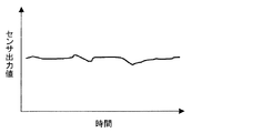
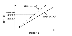
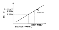
図3に示すように、まずECU37(図1参照。用語に付した符号については以下同じ)により、瞬時スート濃度測定タイプのスートセンサ41aの出力値(スート排出量)Aを読み込む(ステップS21)。なお、図5に、瞬時スート濃度測定タイプのスートセンサを用いた場合、スートセンサ出力値と時間との関係(スート排出量がほぼ一定の場合)を模式的に示す。次に、温度センサ36から排気温度を読み込み、回転センサ38からエンジンの回転数を読み込み、ECU37の初期設定燃料噴射量、排気温度、エンジン回転数等から、エンジンから排出されるであろう推定スート排出量Bを算定する(ステップS22)。次に、推定スート排出量Bをスート排出量Aで割り、その除算結果(誤差判定基準値=│1−(B/A)│)が誤差閾値以上か否かを判定する(ステップS23)。そして、誤差判定基準値が誤差閾値以上ではない(誤差閾値未満である)場合は(NO)、再度ステップS21から処理を行う。一方、誤差判定基準値が誤差閾値以上の場合には(YES)、ステップS21、S22で読み込んだスートセンサ出力値、エンジン回転数、排気温度等から実際の燃料噴射量(実燃料噴射量)を求め、初期設定燃料噴射量を実燃料噴射量に補正して(ステップS24)、再度ステップS21から処理を行う。なお、図7、8に、エンジンの初期設定燃料噴射量を実際の燃料噴射量に補正する第1及び第2の例を模式的に示す。すなわち、エンジンから排出されるであろう推定スート排出量Bの算定に用いられるエンジンの回転数、排気ガスの温度及びエンジンの初期設定燃料噴射量等を含むスート排出量推定用要素のうち、エンジンの初期設定燃料噴射量以外の要素が一定であった場合、初期における燃料噴射量とスート排出量との関係は、図7、8において実線で示される。ここで、初期設定燃料噴射量、排気温度、エンジンの回転数等から導かれる推定スート排出量Bと、スートセンサによって測定されるその時のスート排出量Aとに基づいて設定される誤差判定基準値と、誤差閾値とを比較する。この時、誤差判定基準値が誤差閾値以上の場合には、図7における点線で示すように、その燃料噴射量におけるスート排出量のマップを補正してもよいし、図8に示すように、初期設定燃料噴射量F0を実燃料噴射量Fに補正してもよい。このように二種類の補正をシステムによって使い分けることができる。
As shown in FIG. 3, first, an output value (soot discharge amount) A of the soot sensor 41a of the instantaneous soot concentration measurement type is read by the ECU 37 (see FIG. 1; the same reference numerals are used hereinafter) (step S21). FIG. 5 schematically shows the relationship between the soot sensor output value and time (when the soot discharge amount is substantially constant) when an instantaneous soot concentration measurement type soot sensor is used. Next, the exhaust temperature is read from the
以上説明したように、瞬時スート濃度測定タイプのスートセンサを用いた場合、スートセンサ41aの出力値を用いてECU37の初期設定燃料噴射量を補正することにより、個体バラツキや経時的な変動を避け得ない燃料噴射器の燃料噴射量を正しい値にすることが可能となる。これにより、マッピングによるスート排出量の予測精度を高めてエンジンの実燃料噴射量を最適に制御することが可能となり、常に、燃焼効率のよい燃料噴射量での燃焼が可能となることで、燃費の悪化という問題をも解決することができる。
As described above, when an instantaneous soot concentration measurement type soot sensor is used, individual variations and fluctuations over time cannot be avoided by correcting the initial fuel injection amount of the
図4は、累積スート量測定タイプのスートセンサを用いた場合の、ディーゼル車のエンジンシステムの制御系における制御動作を模式的に示すフローチャート図である。 FIG. 4 is a flowchart schematically showing a control operation in a control system of an engine system of a diesel vehicle when a soot sensor of a cumulative soot amount measurement type is used.
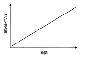
図4に示すように、まず、ECU37(図1参照。用語に付した符号については以下同じ)により、累積スート量測定タイプのスートセンサ41bの出力値(スート排出量)Xを読み込み(ステップS31)、そのスートセンサ出力値Xから、1回前の測定値Cを減算して現在のスート排出量Aを求める(ステップS32)。なお、図6に、累積スート濃度測定タイプのスートセンサを用いた場合、スートセンサ出力値と時間との関係(スート排出量がほぼ一定の場合)を模式的に示す。次に、1回前の測定値Cに今回のスートセンサ出力値Xを登録しておく(ステップS33)。次に、温度センサ36から排気温度を読み込み、回転センサ38からエンジンの回転数を読み込み、ECU37の初期設定燃料噴射量、排気温度、エンジン回転数等から、エンジンから発生するであろう推定スート排出量Bを算定する(ステップS34)。次に、推定スート排出量Bを現在のスート排出量Aで割り、その除算結果(誤差判定基準値=│1−(B/A)│)が誤差閾値以上か否かを判定する(ステップS35)。そして、誤差判定基準値が誤差閾値以上でない(誤差閾値未満である)場合は(NO)、再度ステップS31から処理を行う。一方、誤差判定基準値が誤差閾値以上の場合には(YES)、ステップS32、S34で計算した現在のスート濃度、エンジン回転数、排気温度等から実際の燃料噴射量(実燃料噴射量)を求め、指示燃料噴射量を実燃料噴射量に補正して(ステップS36)、再度ステップS31から処理を行う。なお、瞬時スート濃度測定タイプのスートセンサを用いた場合と同様に、二種類の補正をシステムによって使い分けることができる。
As shown in FIG. 4, first, an output value (soot discharge amount) X of a
以上説明したように、累積スート量測定タイプのスートセンサを用いた場合も、瞬時スート濃度測定タイプのスートセンサを用いた場合と同様な効果を発揮することができる。 As described above, even when the soot sensor of the cumulative soot amount measurement type is used, the same effect as when the soot sensor of the instantaneous soot concentration measurement type is used can be exhibited.
本発明は、ディーゼルエンジンを搭載した各種車両等を製造する自動車工業等の各種産業分野において有効に利用される。 The present invention is effectively used in various industrial fields such as the automobile industry for manufacturing various vehicles equipped with diesel engines.
11…ディーゼルエンジン、21…酸化触媒、22…DPF、36…温度センサ、37…ECU(コンピュータの一例)、38…回転センサ、39…アクセル開度変化センサ、41a…瞬時スート濃度測定タイプのスートセンサ、41b…累積スート濃度測定タイプのスートセンサ、42…温度センサ、43…メモリ、50…走行距離センサ。
DESCRIPTION OF SYMBOLS 11 ... Diesel engine, 21 ... Oxidation catalyst, 22 ... DPF, 36 ... Temperature sensor, 37 ... ECU (an example of a computer), 38 ... Rotation sensor, 39 ... Accelerator opening change sensor, 41a ... Soot sensor of instantaneous soot
Claims (15)
スートセンサを用いて、前記エンジンから排出される排気ガスに含まれるスート排出量を測定する第1のステップと、
少なくとも前記エンジンの回転数、前記排気ガスの温度及び前記エンジンの初期設定燃料噴射量を含むスート排出量推定用要素に基づいて、推定スート排出量を算定する第2のステップと、
前記スート排出量及び前記推定スート排出量に基づいて設定される誤差判定基準値と、誤差閾値とを比較する第3のステップと、
前記誤差判定基準値が、前記誤差閾値以上である場合、少なくとも前記スート排出量、前記エンジンの回転数及び前記排気ガスの温度を含むエンジンの実際の燃料噴射量算出要素に基づいて前記エンジンの実際の燃料噴射量を算定し、前記エンジンの初期設定燃料噴射量を前記実際の燃料噴射量に補正してから、前記第1のステップに戻るか、又は前記誤差判定基準値が、前記誤差閾値未満である場合、前記エンジンの初期設定燃料噴射量を補正することなくそのまま前記第1のステップに戻る第4のステップと、を含むことを特徴とする燃料噴射量の制御方法。 A fuel injection amount control method for controlling the fuel injection amount of an engine by correcting the fuel injection amount from an initial set value based on a predetermined condition during traveling,
A first step of measuring a soot emission amount contained in an exhaust gas exhausted from the engine using a soot sensor;
A second step of calculating an estimated soot emission amount based on at least a soot emission estimation element including an engine speed, an exhaust gas temperature, and an initial fuel injection amount of the engine;
A third step of comparing an error determination reference value set based on the soot discharge amount and the estimated soot discharge amount with an error threshold;
When the error determination reference value is equal to or greater than the error threshold, the actual engine injection amount is calculated based on an actual fuel injection amount calculation factor of the engine including at least the soot emission amount, the engine speed, and the exhaust gas temperature. The fuel injection amount is calculated and the initial fuel injection amount of the engine is corrected to the actual fuel injection amount, and then the process returns to the first step, or the error determination reference value is less than the error threshold value. If so, a fourth step of returning to the first step without correcting the initial fuel injection amount of the engine is included.
C=│1−(B/A)│………(1)
(上記式(1)中、Aはスート排出量、Bは推定スート排出量、Cは誤差判定基準値をそれぞれ示す。) 2. The fuel injection amount control method according to claim 1, wherein a value calculated from a relationship represented by the following expression (1) between the estimated soot discharge amount and the soot discharge amount is used as the error determination reference value.
C = │1- (B / A) │ …… (1)
(In the above formula (1), A represents the soot discharge amount, B represents the estimated soot discharge amount, and C represents the error determination reference value.)
スートセンサを有し、前記スートセンサによって、前記エンジンから排出される排気ガスに含まれるスート排出量を測定することが可能なスート排出量測定手段と、
少なくとも前記エンジンの回転数、前記排気ガスの温度及び前記エンジンの初期設定燃料噴射量を含むスート排出量推定用要素に基づいて推定される推定スート排出量を算定することが可能な推定スート排出量算定手段と、
前記スート排出量及び前記推定スート排出量に基づいて設定される誤差判定基準値と、誤差閾値とを比較することが可能な誤差判定基準値・誤差閾値比較手段と、
前記誤差判定基準値が、前記誤差閾値以上である場合、少なくとも前記スート排出量、前記エンジンの回転数及び前記排気ガスの温度を含むエンジンの実際の燃料噴射量算出要素に基づいて前記エンジンの実際の燃料噴射量を算定し、前記エンジンの初期設定燃料噴射量を前記実際の燃料噴射量に補正してから、前記スート排出量測定手段による前記スート排出量の測定に戻るか、又は前記誤差判定基準値が、前記誤差閾値未満である場合、前記エンジンの初期設定燃料噴射量を補正することなくそのまま前記スート排出量測定手段による前記スート排出量の測定に戻ることが可能な燃料噴射量補正手段と、を備えたことを特徴とする燃料噴射量の制御システム。 A fuel injection amount control system capable of controlling a fuel injection amount of an engine from an initial set value by correcting the fuel injection amount based on a predetermined condition during traveling,
A soot emission measuring means capable of measuring the soot emission contained in the exhaust gas discharged from the engine by the soot sensor;
Estimated soot emission amount capable of calculating an estimated soot emission amount estimated based on a soot emission estimation element including at least the engine speed, the exhaust gas temperature, and the initial fuel injection amount of the engine A calculation means;
An error determination reference value / error threshold comparison means capable of comparing an error determination reference value set based on the soot discharge amount and the estimated soot discharge amount with an error threshold;
When the error determination reference value is equal to or greater than the error threshold, the actual engine injection amount is calculated based on an actual fuel injection amount calculation factor of the engine including at least the soot emission amount, the engine speed, and the exhaust gas temperature. The fuel injection amount of the engine is calculated and the initial fuel injection amount of the engine is corrected to the actual fuel injection amount, and then the soot discharge measuring unit returns to the measurement of the soot discharge amount or the error determination is performed. When the reference value is less than the error threshold, the fuel injection amount correcting means that can return to the measurement of the soot discharge amount by the soot discharge amount measuring means without correcting the initial fuel injection amount of the engine. And a fuel injection amount control system.
C=│1−(B/A)│………(1)
(上記式(1)中、Aはスート排出量、Bは推定スート排出量、Cは誤差判定基準値をそれぞれ示す。) The fuel injection amount control system according to claim 6, wherein the error determination reference value is a value calculated from a relationship represented by the following expression (1) between the estimated soot discharge amount and the soot discharge amount.
C = │1- (B / A) │ …… (1)
(In the above formula (1), A represents the soot discharge amount, B represents the estimated soot discharge amount, and C represents the error determination reference value.)
前記コンピュータを、下記(1)〜(4)の手段として機能させることが可能なことを特徴とする燃料噴射量の制御プログラム。
(1)スートセンサに、前記エンジンから排出される排気ガスに含まれるスート排出量を測定させることが可能なスート排出量測定手段、
(2)少なくとも前記エンジンの回転数、前記排気ガスの温度及び前記エンジンの初期設定燃料噴射量を含むスート排出量推定用要素に基づいて推定される推定スート排出量を算定することが可能な推定スート排出量算定手段、
(3)前記スート排出量及び前記推定スート排出量に基づいて設定される誤差判定基準値と、誤差閾値とを比較することが可能な誤差判定基準値・誤差閾値比較手段、
(4)前記誤差判定基準値が、前記誤差閾値以上である場合、少なくとも前記スート排出量、前記エンジンの回転数及び前記排気ガスの温度を含むエンジンの実際の燃料噴射量算出要素に基づいて前記エンジンの実際の燃料噴射量を算定し、前記エンジンの初期設定燃料噴射量を前記実際の燃料噴射量に補正してから、前記スート排出量測定手段による前記スート排出量の測定に戻るか、又は前記誤差判定基準値が、前記誤差閾値未満である場合、前記エンジンの初期設定燃料噴射量を補正することなくそのまま前記スート排出量測定手段による前記スート排出量の測定に戻ることが可能な燃料噴射量補正手段。 A computer-readable engine fuel injection amount control program for controlling an engine fuel injection amount by correcting from an initial set value based on a predetermined condition during traveling,
A fuel injection amount control program capable of causing the computer to function as the following means (1) to (4).
(1) Soot emission measuring means capable of causing the soot sensor to measure the soot emission contained in the exhaust gas exhausted from the engine;
(2) Estimate capable of calculating an estimated soot emission amount estimated based on a soot emission amount estimation element including at least the engine speed, the exhaust gas temperature, and the initial fuel injection amount of the engine Soot emission calculation means,
(3) an error determination reference value / error threshold comparison means capable of comparing an error determination reference value set based on the soot discharge amount and the estimated soot discharge amount with an error threshold;
(4) When the error determination reference value is greater than or equal to the error threshold, the actual fuel injection amount calculation factor of the engine including at least the soot emission amount, the engine speed, and the exhaust gas temperature is used. Calculating the actual fuel injection amount of the engine and correcting the initial fuel injection amount of the engine to the actual fuel injection amount, and then returning to the measurement of the soot discharge amount by the soot discharge measuring means, or When the error determination reference value is less than the error threshold, the fuel injection that can return to the measurement of the soot discharge amount by the soot discharge amount measuring means without correcting the initial fuel injection amount of the engine Amount correction means.
C=│1−(B/A)│………(1)
(上記式(1)中、Aはスート排出量、Bは推定スート排出量、Cは誤差判定基準値をそれぞれ示す。) 12. The fuel injection amount control program according to claim 11, wherein the error determination reference value is a value calculated from a relationship represented by the following expression (1) between the estimated soot discharge amount and the soot discharge amount.
C = │1- (B / A) │ …… (1)
(In the above formula (1), A represents the soot discharge amount, B represents the estimated soot discharge amount, and C represents the error determination reference value.)
Priority Applications (1)
| Application Number | Priority Date | Filing Date | Title |
|---|---|---|---|
| JP2005068655A JP4537232B2 (en) | 2005-03-11 | 2005-03-11 | Control method of fuel injection amount |
Applications Claiming Priority (1)
| Application Number | Priority Date | Filing Date | Title |
|---|---|---|---|
| JP2005068655A JP4537232B2 (en) | 2005-03-11 | 2005-03-11 | Control method of fuel injection amount |
Publications (2)
| Publication Number | Publication Date |
|---|---|
| JP2006250058A JP2006250058A (en) | 2006-09-21 |
| JP4537232B2 true JP4537232B2 (en) | 2010-09-01 |
Family
ID=37090810
Family Applications (1)
| Application Number | Title | Priority Date | Filing Date |
|---|---|---|---|
| JP2005068655A Expired - Fee Related JP4537232B2 (en) | 2005-03-11 | 2005-03-11 | Control method of fuel injection amount |
Country Status (1)
| Country | Link |
|---|---|
| JP (1) | JP4537232B2 (en) |
Families Citing this family (6)
| Publication number | Priority date | Publication date | Assignee | Title |
|---|---|---|---|---|
| US8100107B2 (en) * | 2010-07-21 | 2012-01-24 | Ford Global Technologies, Llc | Method and system for engine control |
| US9441570B2 (en) | 2012-12-07 | 2016-09-13 | Ethanol Boosting Systems, Llc | Gasoline particulate reduction using optimized port and direct injection |
| WO2014089304A1 (en) | 2012-12-07 | 2014-06-12 | Ethanol Boosting Systems, Llc | Port injection system for reduction of particulates from turbocharged direct injection gasoline engines |
| EP3516195A4 (en) | 2016-09-26 | 2020-11-18 | Ethanol Boosting Systems LLC | Gasoline particulate reduction using optimized port fuel injection plus direct injection |
| DE102020215291A1 (en) * | 2020-12-03 | 2022-06-09 | Robert Bosch Gesellschaft mit beschränkter Haftung | Method and computing unit for operating an internal combustion engine with a particle filter |
| US11566568B2 (en) * | 2021-03-19 | 2023-01-31 | Ford Global Technologies, Llc | Valve timing modulation for EGR balancing |
Citations (2)
| Publication number | Priority date | Publication date | Assignee | Title |
|---|---|---|---|---|
| JP2001355433A (en) * | 2000-06-09 | 2001-12-26 | Toyota Motor Corp | Exhaust emission control device for internal combustion engine |
| JP2004360572A (en) * | 2003-06-04 | 2004-12-24 | Toyota Motor Corp | Internal combustion engine controller |
-
2005
- 2005-03-11 JP JP2005068655A patent/JP4537232B2/en not_active Expired - Fee Related
Patent Citations (2)
| Publication number | Priority date | Publication date | Assignee | Title |
|---|---|---|---|---|
| JP2001355433A (en) * | 2000-06-09 | 2001-12-26 | Toyota Motor Corp | Exhaust emission control device for internal combustion engine |
| JP2004360572A (en) * | 2003-06-04 | 2004-12-24 | Toyota Motor Corp | Internal combustion engine controller |
Also Published As
| Publication number | Publication date |
|---|---|
| JP2006250058A (en) | 2006-09-21 |
Similar Documents
| Publication | Publication Date | Title |
|---|---|---|
| JP4042476B2 (en) | Exhaust gas purification device for internal combustion engine | |
| US7458206B2 (en) | Exhaust gas purification system of internal combustion engine | |
| JP4389606B2 (en) | Exhaust gas purification device for internal combustion engine | |
| JP4973992B2 (en) | Exhaust gas purification device for internal combustion engine | |
| EP1921289B1 (en) | Exhaust gas purifying apparatus for measuring particles | |
| JP5833864B2 (en) | Exhaust gas treatment method and exhaust gas treatment control system for internal combustion engine | |
| JP2004245123A (en) | Exhaust emission control device of internal combustion engine | |
| JP2006226119A (en) | Exhaust emission control device for internal combustion engine | |
| WO2004015249A1 (en) | Filter control method and device | |
| WO2004016916A1 (en) | Filter control device | |
| US20080098724A1 (en) | Exhaust gas purifying apparatus | |
| JP2004316428A (en) | Method and program for predicting soot deposition quantity on exhaust gas emission filter | |
| JP4537232B2 (en) | Control method of fuel injection amount | |
| WO2008004704A1 (en) | Control unit and control method for internal combustion engine | |
| JP2006063970A (en) | Exhaust emission control device of internal combustion engine | |
| JP2006250048A (en) | Regeneration control method of filter for exhaust emission control | |
| WO2020066931A1 (en) | Estimation device and vehicle | |
| JP2004132358A (en) | Filter control device | |
| JP4692334B2 (en) | Exhaust particulate collection filter regeneration control device | |
| JP4075724B2 (en) | Exhaust gas purification device for internal combustion engine | |
| JP4605101B2 (en) | Exhaust gas purification device for internal combustion engine | |
| JP5862497B2 (en) | Catalyst deterioration judgment device | |
| JP4192617B2 (en) | Exhaust gas purification device for internal combustion engine | |
| JP2016130456A (en) | Internal combustion engine control unit | |
| JP4660446B2 (en) | Exhaust gas purification device for internal combustion engine |
Legal Events
| Date | Code | Title | Description |
|---|---|---|---|
| A621 | Written request for application examination |
Free format text: JAPANESE INTERMEDIATE CODE: A621 Effective date: 20071114 |
|
| A977 | Report on retrieval |
Free format text: JAPANESE INTERMEDIATE CODE: A971007 Effective date: 20091217 |
|
| TRDD | Decision of grant or rejection written | ||
| A01 | Written decision to grant a patent or to grant a registration (utility model) |
Free format text: JAPANESE INTERMEDIATE CODE: A01 Effective date: 20100615 |
|
| A01 | Written decision to grant a patent or to grant a registration (utility model) |
Free format text: JAPANESE INTERMEDIATE CODE: A01 |
|
| A61 | First payment of annual fees (during grant procedure) |
Free format text: JAPANESE INTERMEDIATE CODE: A61 Effective date: 20100617 |
|
| FPAY | Renewal fee payment (event date is renewal date of database) |
Free format text: PAYMENT UNTIL: 20130625 Year of fee payment: 3 |
|
| R150 | Certificate of patent or registration of utility model |
Free format text: JAPANESE INTERMEDIATE CODE: R150 |
|
| LAPS | Cancellation because of no payment of annual fees |