JP4598552B2 - Device management apparatus and device management method - Google Patents
Device management apparatus and device management method Download PDFInfo
- Publication number
- JP4598552B2 JP4598552B2 JP2005029366A JP2005029366A JP4598552B2 JP 4598552 B2 JP4598552 B2 JP 4598552B2 JP 2005029366 A JP2005029366 A JP 2005029366A JP 2005029366 A JP2005029366 A JP 2005029366A JP 4598552 B2 JP4598552 B2 JP 4598552B2
- Authority
- JP
- Japan
- Prior art keywords
- devices
- transmission
- management apparatus
- distance
- device management
- Prior art date
- Legal status (The legal status is an assumption and is not a legal conclusion. Google has not performed a legal analysis and makes no representation as to the accuracy of the status listed.)
- Expired - Lifetime
Links
Images


Landscapes
- Selective Calling Equipment (AREA)
Description
本発明は、ビル、家屋、船などの建造物に設置された照明器具や空調室内機などの複数の設備機器を管理する機器管理装置および機器管理方法に関する。 The present invention relates to a device management apparatus and a device management method for managing a plurality of equipment such as lighting fixtures and air conditioning indoor units installed in buildings such as buildings, houses, and ships.
従来、建造物内のパーティションの変更に合わせて照明器具や空気室内機などの設備機器のグループ(グループ運転させるためのグループ)を変更する場合、入力部よりグループ編成を行う旨の指示が入力されると、グループ編成用の画面を表示部に表示する。そして、入力部によってグルーピング方法が指定されると、その方法に応じて設定された2個のユニットを同一グループに所属するように設定していた(例えば、特許文献1参照)。
前述した従来のグループ設定は、作業者が入力部を操作して行っているため、例えば、超高層ビルなどの設備機器に対してグループ設定を行う場合には、作業者に負担がかかり、設定操作を誤ることもあった。 Since the conventional group setting described above is performed by the operator operating the input unit, for example, when performing group setting for equipment such as a skyscraper, the operator is burdened and set. The operation was sometimes wrong.
本発明は、前述のような課題を解決するためになされたもので、グループ設定を容易に行うことのできる機器管理装置および機器管理方法を提供することを目的とする。また、建造物内に壁などの遮蔽物があってもそれを自動的に検出することのできる機器管理装置および機器管理方法を提供することを目的とする。 The present invention has been made to solve the above-described problems, and an object of the present invention is to provide a device management apparatus and a device management method capable of easily performing group setting. It is another object of the present invention to provide a device management apparatus and a device management method that can automatically detect a shield such as a wall in a building.
本発明に係る機器管理装置は、建造物に設置された複数の機器の相対位置を検出する機器管理装置において、各機器間での送受信によって得られた送受信情報を入力する通信手段と、通信手段により入力された送受信情報に基づいて各機器の相対位置を算出する位置算出手段と、位置算出手段による各機器の相対位置の算出誤差が所定の閾値より大きい場合に、これらの機器間に遮蔽物が存在するものと推定する遮蔽物推定手段とを備えたものである。 An apparatus management apparatus according to the present invention includes a communication unit that inputs transmission / reception information obtained by transmission / reception between apparatuses in a device management apparatus that detects a relative position of a plurality of apparatuses installed in a building; position calculating means for calculating the relative position of each device based on the reception information inputted by, when the calculated error in the relative position of each device by the position calculation means is greater than a predetermined threshold, obstacle between these devices It is provided with the shielding object estimation means which presumes that there exists.
また、本発明に係る機器管理装置は、建造物に設置された複数の機器をグループ運転させるために、これらの機器を1以上のグループに分類する機器管理装置において、各機器間での送受信によって得られた送受信情報を入力する通信手段と、通信手段により入力された送受信情報に基づいて複数の機器を1以上のグループに分類する分類手段と、通信手段により入力された送受信情報に基づいて各機器の相対位置を算出する位置算出手段と、位置検出手段による各機器の相対位置の算出誤差が所定の閾値より大きい場合に、これらの機器間に遮蔽物が存在するものと推定する遮蔽物推定手段とを備え、分類手段は、遮蔽物推定手段により遮蔽物が存在すると推定された場合に、遮蔽物を境界として複数の機器を2以上のグループに分類する。 In addition, the device management apparatus according to the present invention is a device management apparatus that classifies a plurality of devices installed in a building into one or more groups in order to perform group operation . communication means for inputting the reception information obtained, a classification means for classifying a plurality of devices to one or more groups based on reception information inputted by the communication means, each based on the reception information inputted by the communication unit A position calculation unit that calculates the relative position of the device, and a shield estimation that estimates that there is a shield between the devices when the relative position calculation error by the position detection unit is greater than a predetermined threshold and means, classifying means, when it is estimated that the shield exists by obstacle estimating means for classifying a plurality of the devices into two or more groups of the shield as a boundary
本発明においては、各機器間での送受信によって得られた送受信情報に基づいて各機器の相対位置を算出し、各機器の相対位置の算出誤差が所定の閾値より大きい場合に、これらの機器間に遮蔽物が存在するものと推定する。これにより、遮蔽物の存在を容易に把握できるようになり、遮蔽物によって発生していた各機器の相対位置の検出誤差を確実に修正することが可能となる。その結果、各機器の相対位置の検出精度が向上する。 In the present invention, the relative position of each device is calculated based on transmission / reception information obtained by transmission / reception between the devices, and when the relative position calculation error of each device is larger than a predetermined threshold, between these devices. It is estimated that there is a shielding object in Thereby, the presence of the shielding object can be easily grasped, and the detection error of the relative position of each device generated by the shielding object can be surely corrected. As a result, the relative position detection accuracy of each device is improved.
また、本発明においては、各機器間での送受信によって得られた送受信情報に基づいて各機器の相対位置を算出し、各機器の相対位置の算出誤差が所定の閾値より大きい場合には、これらの機器間に遮蔽物が存在するものと推定し、遮蔽物が存在すると推定したときには、遮蔽物を境界として複数の機器を2以上のグループに分類する。これにより、建造物内のパーティション変更などによって発生する各機器のグループ変更を自動的に行うことができるようになり、作業者の負担を大幅に軽減できる。また、作業者が入力部を操作してパーティションの変更を行う必要がないので、設定操作を誤るといった人的ミスを未然に防止できる。 In the present invention, the relative position of each device is calculated based on transmission / reception information obtained by transmission / reception between the devices, and when the calculation error of the relative position of each device is larger than a predetermined threshold, When it is estimated that there is a shielding object between the devices, and the shielding object is estimated to exist, the plurality of devices are classified into two or more groups with the shielding object as a boundary. As a result, it becomes possible to automatically change the group of each device that occurs due to a partition change in the building, and the burden on the operator can be greatly reduced. In addition, since it is not necessary for the operator to change the partition by operating the input unit, it is possible to prevent a human error such as an error in the setting operation.
実施の形態1.
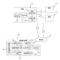
図1は、本発明の実施の形態1に係る機器管理装置の構成を示すブロック図である。
機器10は、例えば、ビルの各フロアの天井に配設された照明器具や空調室内機などの設備機器で、無線通信手段11と、距離計測手段12と、処理手段13と、データ保持手段14とを有している。無線通信手段11は、隣接する機器10の無線通信手段11との間で電波の送受信をする。この無線通信手段11による無線通信は、それぞれ少なくとも3台の機器10との間で行われるものとする。距離計測手段12は、無線通信手段11に受信された電波の強度に基づいて隣接機器10との距離を測定する。
Embodiment 1 FIG.
FIG. 1 is a block diagram showing a configuration of a device management apparatus according to Embodiment 1 of the present invention.
The
各機器10の処理手段13は、隣接する機器10との距離を計測する際、まず、予め設定された自己のIDを無線通信手段11に通知して送信電波に含ませ、隣接する機器10からの電波が受信されたときは、その電波に含まれているIDを抽出し、受信電波の強度に基づく距離が距離計測手段12によって計測されたときは、そのIDと計測距離とを関連付けてデータ保持手段14に一時的に保存する。また、後述する機器管理装置20により設定される位置座標、アドレスなどが通信網30を介して受信されたときは、それらを自己の機器データとしてデータ保持手段14に保存する。なお、このデータ保持手段14には、予め機器の種別を示す情報がデータとして保存されている。
When measuring the distance from the
機器管理装置20は、通信網30に接続された通信手段21と、位置算出手段22と、遮蔽物推定手段23と、処理手段24と、機器管理手段25と、表示手段26とを備えている。通信手段21は、通信網30に配置された複数の無線局(図示せず)を通じて各機器10と通信を行い、各機器10から送受信情報を入力する。なお、送受信情報には、各機器10間での送受信信号の強度情報、各機器10間での送受信信号の伝送時間情報、各機器10間の距離情報などがある(本実施の形態および実施の形態2においては、送受信情報として各機器10間の距離情報を用いて説明する)。また、通信手段21は、有線に代えて、直接、無線局を通じて複数の機器10と無線通信を行うようにしてもよい。
The
位置算出手段22は、各機器10に保存された計測距離(送受信情報)を基に、通信網30上の各機器10の相対位置(位置座標)を算出する。例えば、予め設定された基準(原点)となる機器10とその機器に隣接する2台又は3台の機器との間の計測距離に基づいて機器10の角度を三角関数により決定し、決定した角度と計測距離とに基づいて基準の機器10に隣接する各機器10の位置座標を求める。そして、位置座標の決定した機器10に隣接する他の機器10について、前述した方法により隣接の機器10の位置座標を求め、これを順に繰り返して全ての機器10の位置座標を求める。
The position calculation means 22 calculates the relative position (position coordinates) of each
前述した位置座標は、2次元座標系での機器10の配置位置を示すものであって、建物に配置されている機器10(設備機器)の位置とは多少の誤差がある。また、図2に示すように、建物内に遮蔽物の壁40などがあった場合、エリアB側の計算上の機器位置(位置座標)が破線の円で示すようになり、実際に配置されている機器10との誤差が大きくなる。これは、エリアB側の各機器10が壁40によって大きく減衰する電波強度から計測した距離を位置座標の算出に取り入れたためであり、機器間の計測距離と計算上の距離とに大きな差が生じる。なお、図2に示すエリアA側の計算上の機器位置(実線の円)は、機器間の計測距離と計算上の距離とがほぼ一致している状態を示し、エリアB側の計算上の機器位置(実線の円)は、後述する遮蔽物推定手段23によって変更された状態を示している。
The position coordinates described above indicate the arrangement position of the
遮蔽物推定手段23は、位置算出手段22によって算出された位置座標から求めた機器間の距離とその機器間の計測距離との誤差が予め設定された閾値より大きいとき、その機器間に壁40が存在すると推定して、その機器間の計測距離が短くなるように所定数を乗算し、その距離値をデータとして位置座標を変更するように位置算出手段22に通知する。この通知によって変更された計算上の距離と変更した機器間の計測距離との誤差が前記の閾値より大きい場合は、その誤差が閾値より小さくなるまで前述した変更処理を繰り返し行う。また、前記の誤差と閾値とを比較した際に距離の誤差が閾値より小さいときは、その都度、位置座標に基づいて該当機器10を処理手段24を通じて表示手段26に表示し、壁40の位置を推定した場合は、推定位置に基づいて壁40を表示する。
When the error between the distance between the devices calculated from the position coordinates calculated by the position calculation means 22 and the measured distance between the devices is larger than a preset threshold value, the shielding
処理手段24は、各機器10による機器間の距離計測が終了すると、各機器10のIDと関連付けられた計測距離を通信手段21を通じて受信し、位置算出手段22に位置算出の指示を通知する。位置算出手段22によって各機器10の位置座標が算出されたときは、遮蔽物推定手段23に対し前述した処理を行わせるように指示を出し、遮蔽物推定手段23によって壁40の位置が推定されこの壁40の存在から機器10の位置が変更されたときは、前述したようにその結果を表示手段26に表示し、かつ、遮蔽物推定手段23によって変更された各機器10の配置及び推定した壁40をシステム上のデータとして機器管理手段25に書き込む。なお、機器管理手段25に書き込んだ各機器10にアドレスが付与された場合は、アドレスと関連付けて保存し、その情報をデータとして通信網30上に配信して、該当する機器10にそれぞれ受信させる。
When the distance measurement between the devices by each
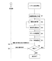
次に、本実施の形態1の動作を図3のフローチャートに基づいて説明する。図3は機器管理装置における遮蔽物推定時の動作を示すフローチャートである。
各機器10の距離計測手段12により相互に隣接機器10との距離が計測されると(S11)、機器管理装置20の処理手段24は、通信手段21を通じて、各機器10に保存された機器間の計測距離をIDと共に読み込んで位置算出手段22に通知する。位置算出手段22は、前述した算出方法に基づいて、予め設定された基準(原点)の機器10から順に2次元座標系における隣接機器10の位置座標を算出し(S12)、全ての機器10の位置座標を算出したときは、その旨を処理手段24を通じて遮蔽物推定手段23に通知する。
Next, the operation of the first embodiment will be described based on the flowchart of FIG. FIG. 3 is a flowchart showing an operation at the time of shielding object estimation in the device management apparatus.
When the
ここで、S12の位置計算においては、計測距離に誤差がある場合には、4台以上の機器相互の計測距離を用いると平面条件を満たさないなどの矛盾が生じる。そのため、計算位置上で計算される各機器間の距離とS11において計測した距離との間に誤差が生じる。そこで、遮蔽物推定手段23は、位置算出手段22から通知を受けると、S12によって計算された位置座標を元に、各機器の計算位置上の距離を計算し、該計算位置上の距離とS11で計測した計測距離とを比較し前記誤差を算出する(S13)。
Here, in the position calculation of S12, if there is an error in the measurement distance, a contradiction such as not satisfying the plane condition occurs if the measurement distance between four or more devices is used. Therefore, an error occurs between the distance between each device calculated on the calculation position and the distance measured in S11. Therefore, when receiving the notification from the position calculating
次に、全ての機器間における誤差(距離差)と予め設定された閾値とを比較し(S14)、閾値より大きい誤差が存在すると判断した場合は、機器間に壁40が存在すると推定してその位置を検出する(S15)。この位置検出は、あくまでも推定で、単に機器間の中央に位置しているものとして検出する。その後は、誤差が閾値より大きい全ての機器間の計測距離、例えば図2に示すように、機器10aと機器10bとの間の計測距離が短くなるように計測距離を変更する(S16)。この変更は例えば壁40による信号の減衰に基づき、一定量を計測距離に乗算して行う。
Next, an error (distance difference) between all the devices is compared with a preset threshold value (S14), and if it is determined that an error larger than the threshold value exists, it is estimated that a wall 40 exists between the devices. The position is detected (S15). This position detection is merely an estimate, and is detected simply as being located at the center between devices. After that, the measurement distance is changed so that the measurement distance between all the devices whose error is larger than the threshold, for example, the measurement distance between the
そして、誤差が閾値より大きい全ての機器間に対する変更後の計測距離を位置算出手段22に通知する。この時、位置算出手段22は、遮蔽物推定手段23から受け取った距離値(変更された計測距離)を基に各機器10の位置座標を前述した方法で再計算する(S12)。その後、S13で計算位置上の距離と計測距離との誤差を再計算した後、S14において閾値より大きい誤差がまだ存在するか否かを判定し、閾値より大きい誤差が存在すると判断した場合には、S12〜S16の処理を繰り返す。
また、S14において、全ての誤差が閾値より小さいと判断した場合には、遮蔽物推定位置を保存し、得られた機器位置および推定した遮蔽物の位置を表示し(S17)、位置検出を終了する。
And the position calculation means 22 is notified of the measurement distance after the change with respect to all the apparatuses with an error larger than a threshold value. At this time, the position calculation means 22 recalculates the position coordinates of each
If it is determined in S14 that all errors are smaller than the threshold value, the estimated shielding position is stored, the obtained device position and the estimated shielding position are displayed (S17), and the position detection is terminated. To do.
以上のように、実施の形態1によれば、機器間の計算上の距離とその間の計測距離との誤差が閾値より大きい場合に、壁などの遮蔽物があると推定して、該当する機器の位置座標を再計算するようにしたので、計算上の機器位置の精度を向上させることができる。また、新たなパーティションが追加された場合でも、それを自動的に検出することが可能になり、このため、自動的にシステム上の運用設定を変更したり、その設定支援を容易に行うことができる。 As described above, according to the first embodiment, when the error between the calculated distance between devices and the measured distance between them is larger than the threshold, it is estimated that there is a shielding object such as a wall, and the corresponding device Since the position coordinates of are recalculated, the accuracy of the device position in the calculation can be improved. In addition, even when a new partition is added, it can be automatically detected. For this reason, it is possible to automatically change the operation settings on the system or easily support the setting. it can.
なお、前記の実施の形態1では、計算上の距離と計測距離との誤差を遮蔽物である壁40の推定基準に用いたが、壁40の推定の評価方法はこれに限定されるものではない。例えば、機器10が存在する範囲の矛盾や、機器配置の規則性の変化などの条件により壁40の位置を推定するようにしてもよい。また、機器10の位置算出、壁40の位置推定は、それぞれ機器管理装置20の位置算出手段22と遮蔽物推定手段23が行うようにしているが、機器10の位置算出、壁40の位置推定を各機器10がそれぞれ分散して計算するようにしてもよいし、機器管理装置20とは別に位置算出手段22、或いは遮蔽物推定手段23を有する装置によって位置計算や位置推定を行うようにしてもよい。
In the first embodiment, the error between the calculated distance and the measured distance is used as the estimation standard for the wall 40 that is a shield. However, the estimation method for estimating the wall 40 is not limited to this. Absent. For example, the position of the wall 40 may be estimated based on conditions such as a contradiction in the range in which the
実施の形態2.
図4は、本発明の実施の形態2に係る機器管理装置の構成を示すブロック図である。なお、図1で説明した実施の形態1と同一又は相当部分には同じ符号を付し説明を省略する。
本実施の形態2における機器管理装置20のアドレス設定手段27は、遮蔽物推定手段23による各機器10の位置関係のチェックや変更が終了すると、その情報をデータとして処理手段24を通じて取得する。そして、基準となる機器10の位置座標に基づいて2次元座標系における基点を設定する。そして、所定の長さdを一辺とする検索範囲を基点からX方向にその長さd毎に移動し、移動した際にその検索範囲内に機器10の位置座標があるとき、その機器10にアドレスを割り当てる。このアドレスの設定は、X方向を列とて複数列ある場合には、列毎に順に連番のアドレスを割り当てていく。なお、前記の長さdは、例えば建築の基準単位(3.3m,4m)であり、この長さdを用いることで効率よくアドレスを設定することができる。
Embodiment 2. FIG.
FIG. 4 is a block diagram showing the configuration of the device management apparatus according to Embodiment 2 of the present invention. In addition, the same code | symbol is attached | subjected to the same or equivalent part as Embodiment 1 demonstrated in FIG. 1, and description is abbreviate | omitted.
The
運用設定推論手段28は、アドレス設定手段27により2次元座標上の各機器10にアドレスが割り当てられると、遮蔽物推定手段23により推定された壁が存在するかどうかを判別する。壁を確認したときは、その壁を境に機器10の運用グループ候補として2分し、遮蔽物推定手段23を通じてフロア上に壁がないと判断したときは、予め設定された枠(モデルパターン)を用いて運用グループの候補を設定する。この枠は、運用のためのグループ運転の広さに応じてそれぞれ用意されており、今までの経験上から決められた大きさである。また、運用グループ候補の設定は、通信手段21で入力した計測距離(送受信情報)に基づいて行われる(即ち、通信手段21で入力した計測距離(送受信情報)に基づいて位置算出手段22で位置座標が算出され、この位置座標をアドレス設定手段27で割り当てたアドレスが、運用グループ候補の設定に用いられる)。
When the address setting means 27 assigns an address to each
処理手段24は、運用設定推論手段28により2次元座標上の各機器10の運用グループ候補が設定されると、その情報をデータとして機器管理手段25に保存し、そのデータをアドレス設定のためにアドレス設定手段27に通知する。また、アドレス設定手段27により運用グループ候補毎に各機器10にアドレスが設定されたときは、その情報をデータとして機器管理手段25に保存する。また、各機器10のIDにそれぞれ関連付けられた機器10の位置座標、アドレスなどをデータとして通信手段21から通信網30に配信し、該当する機器10に受信させる。なお、機器管理装置20には、端末装置である例えばパソコンや各種設定用のリモコンと接続するためのインターフェイス(図示せず)が備えられている。
なお、処理手段24と運用設定推論手段28とで分類手段が構成されるものとする。
When the operation group candidate of each
It is assumed that the
次に、本実施の形態2の動作を図5のフローチャートに基づいて説明する。図5は設備管理システムにおける機器管理装置の動作を示すフローチャートである。なお、図中に示すS23は、遮蔽物推定手段による動作で、実施の形態1で説明した遮蔽物推定手段と同じであるため、簡略化して説明する。
各機器10の距離計測手段12により相互に隣接機器10との距離が計測されると(S21)、機器管理装置20の処理手段24は、通信手段21を通じて、各機器10に保存された機器間の計測距離(送受信情報)をIDと共に読み込んで位置算出手段22に通知する。位置算出手段22は、実施の形態1で述べた算出方法に基づいて、予め設定された基準(原点)の機器10から順に2次元座標系における隣接機器10の相対位置(位置座標)を算出し(S22)、全ての機器10の位置座標を算出したときは、その旨を処理手段24を通じて遮蔽物推定手段23に通知する。
Next, the operation of the second embodiment will be described based on the flowchart of FIG. FIG. 5 is a flowchart showing the operation of the device management apparatus in the facility management system. Note that S23 shown in the figure is an operation performed by the shielding object estimation unit and is the same as the shielding object estimation unit described in the first embodiment, and therefore will be described in a simplified manner.
When the
遮蔽物推定手段23は、機器間の計算上の距離とその間の計測距離との誤差が閾値より小さい場合に、計算上の距離と計測距離が一致していると判断し、その位置関係をそのままとし、前記の誤差が閾値より大きいときは、壁などがあると推定して、その計測距離が短くなるように所定数を乗算し、その距離値を基に、関連する機器10の位置座標を位置算出手段22によって再計算させる(S22,S23)。これを計算上の距離と計測距離との誤差が閾値より小さくなるまで繰り返し行う。
When the error between the calculated distance between the devices and the measured distance between them is smaller than the threshold, the shielding object estimating means 23 determines that the calculated distance and the measured distance are the same, and the positional relationship is kept as it is. When the error is larger than the threshold value, it is estimated that there is a wall or the like, and is multiplied by a predetermined number so that the measurement distance is shortened. Based on the distance value, the position coordinates of the
一方、処理手段24は、遮蔽物推定手段23による各機器10の位置関係のチェック及び変更が終了すると、その情報をアドレス設定手段27に通知する。このアドレス設定手段27は、基準となる機器10の位置座標に基づいて2次元座標系における基点を設定する。そして、所定の長さdを一辺とする検索範囲を基点からX方向にその長さd毎に移動し、移動した際にその検索範囲内に機器10の位置座標があるときその機器10にアドレスを割り当てる。このアドレスの設定は、X方向を列とて複数列ある場合には、列毎に順に連番のアドレスを割り当てていく(S24)。
On the other hand, the
このアドレスの設定が終了すると、運用設定推論手段28は、遮蔽物推定手段23により推定された壁が存在するかどうかを判別する。壁を確認したときは、その壁を境に機器10の運用グループ候補として2分し、遮蔽物推定手段23を通じてフロア上に壁がないと判断したときは、予め設定された枠(正方形、縦長、横長)を用いて、運用グループ候補を設定する(S25)。なお、運用グループ候補の設定方法としては、予め設定された枠を用いる以外にも、(1)各機器10の中から基準の機器10を選択し、基準の機器10との距離が所定距離以下の機器10を基準の機器10と同じグループとして分類する方法、(2)各機器10の中から基準の機器10を選択し、基準の機器10と他の機器10との距離を短い順に並べた場合に、隣接する距離の差分値が所定の閾値以内にある機器10を基準の機器10と同じグループとして分類する方法、(3)空調機などのリモコンがフロア内に複数配置されている場合に、各リモコンと各機器10との距離が所定距離以内の機器10を同じグループとして分類する方法などがある。
When the address setting is completed, the operation setting inference means 28 determines whether or not the wall estimated by the shielding object estimation means 23 exists. When the wall is confirmed, it is divided into two as operation group candidates of the
ここで、(1)(2)については、基準の機器10に対するグループ分類終了後に、グループ外の機器10の中から新たな基準の機器10を選択して、新たな基準の機器10に対するグループ分類を継続させるものとする。このような処理を行うことにより、各機器を個別に操作することなく、最適なグループ分けを自動的に行うことができ、設定作業が削減される。
Here, for (1) and (2), after the group classification for the
そして、その情報をデータとして機器管理手段25に処理手段24を通じて書き込む。処理手段24は、そのデータの書き込みが終了すると、機器管理手段25に書き込まれた機器位置、壁の推定位置、運用グループ候補などのデータを予め接続されたパソコンの表示部に表示する(S26)。このパソコンから修正の指示が出されると(S27)、その修正内容に応じて機器位置の計算、アドレス自動設定、運用グループの候補設定の何れか、又は複数の処理を再度実行させるようにする(S28)。なお、再実行により変更されたときは機器管理手段25に保存する。また、確定の指示を受けたときには、前述した一連の動作、即ち設備管理システムの構築に必要な設定を終了する。
Then, the information is written as data in the device management means 25 through the processing means 24. When the writing of the data is completed, the
以上のように、実施の形態2によれば、設備管理システムにおける運用設定(機器の運用グループ化)を自動的に行って作業者に提示できるようにしたので、各機器10を個別に操作しなくても、通信網30を通してグループ運転の候補の選択や修正を容易に行うことができ、設定作業を軽減できる。また、運用設定の変更についても通信網30上で行うことが可能になり、変更作業が容易となる。
As described above, according to the second embodiment, the operation setting (equipment operation grouping) in the equipment management system can be automatically performed and presented to the operator, so that each
なお、前記の実施の形態2では、グループ候補設定の後で作業者に全てを提示するようにしたが、図6に示すように、機器位置計算と壁推定位置、アドレス自動設定、グループ候補設定の後に、その都度、作業者に提示して修正指示を受けるようにしてもよい。また、これらの内、一つだけ提示して修正指示を受けるようにしてもよい。また、アドレス自動設定の後にグループ候補設定を行っているが、グループ候補を設定した後、その候補のグループに基づいて各機器10のアドレスを設定するようにしてもよい。さらに、前記の実施の形態1,2では、機器管理装置20の各構成を機器10に内蔵させてもよい。
また、図5のフローチャートおいて、S22〜S24の処理を省略して、S21での機器間距離の計測の後に、S25のグループ候補設定処理を行ってもよい。この場合は、壁40の存在については考慮されないものの、各機器10のグループ分けを支障なく行うことができる。このため、各機器10を個別に操作しなくても、グループ運転の候補の選択や修正を容易に行うことができ、設定作業を軽減できるといった効果が、S22〜S24の処理を省略した構成(図4においては、位置算出手段22、遮蔽物推定手段23、アドレス設定手段27を省略した構成)においても、十分に発揮される。
In the second embodiment, everything is presented to the operator after the group candidate setting. However, as shown in FIG. 6, the device position calculation, the estimated wall position, the automatic address setting, and the group candidate setting. After that, the correction instruction may be received by presenting it to the operator. Further, only one of them may be presented to receive a correction instruction. In addition, group candidate setting is performed after address automatic setting. However, after setting a group candidate, the address of each
Further, in the flowchart of FIG. 5, the processing of S22 to S24 may be omitted, and the group candidate setting processing of S25 may be performed after the measurement of the inter-device distance in S21. In this case, although the presence of the wall 40 is not considered, the grouping of the
実施の形態3.
次に、実施の形態3に係る機器管理装置について説明する。なお、本実施の形態に係る機器管理装置の構成は、図4のブロック図に示したものと同様である。
本実施の形態に係る機器管理装置は、各機器10の処理手段13において、他の機器10との送受信信号から受信強度を抽出し、一旦データ保持手段14に保存する。そして、処理手段13は、受信強度をデータ保持手段14から読み出して、送受信情報として機器管理装置20に送信する。受信強度の情報を受け付けた機器管理装置20では、図5に示すS22〜S24と同様の処理を実行し、各機器に対してアドレスを割り当てる。次に、S25のグループ候補設定処理において、処理手段24と運用設定推論手段28とで、各機器10の中から基準の機器10を選択し、基準の機器10で受信した送受信信号の受信強度が所定強度以上の場合に、発信元の機器10を基準の機器10と同じグループとして分類する。基準の機器10に対するグループ分類終了後に、グループ外の機器10の中から新たな基準の機器10を選択して、新たな基準の機器10に対するグループ分類を実施する。そして、この処理は、全ての機器がいずれかのグループに分類させるまで継続実施する。
なお、S25のグループ候補設定処理は、各機器10の中から基準の機器10を選択し、基準の機器10で受信した送受信信号を強度の強い順に並べた場合に、隣接する信号の強度差分値が所定の閾値以内にある発信元の機器10を基準の機器10と同じグループとして分類してもよい。また、各機器10の中から基準の機器10を選択し、基準の機器10で受信した送受信信号の強度に基づく基準の機器10との距離および相対位置を三角法により算出し、各機器10の該相対位置の算出誤差が第2の所定の閾値以内にある機器10を基準の機器10と同じグループとして分類してもよい。
さらに、各機器10の処理手段13では、他の機器10との送受信信号から伝送時間情報を抽出して、この伝送時間情報を送受信情報として機器管理装置20に送信してもよい。この場合、処理手段24と運用設定推論手段28とでは、各機器10の中から基準の機器10を選択し、基準の機器10で受信した送受信信号の伝送時間が所定時間以内の場合に、発信元の機器10を基準の機器10と同じグループとして分類する。
以上のように、実施の形態3によれば、送受信情報として、各機器10間での送受信信号の強度情報、各機器10間での送受信信号の伝送時間情報を用いて、グループ候補設定処理を行うことができる。その結果、各機器10を個別に操作しなくても、通信網30を通してグループ運転の候補の選択や修正を容易に行うことができ、設定作業を軽減できる。また、運用設定の変更についても通信網30上で行うことが可能になり、変更作業が容易となる。
なお、実施の形態3においても、実施の形態2と同様に、S22〜S24の処理を省略した構成(図4においては、位置算出手段22、遮蔽物推定手段23、アドレス設定手段27を省略した構成)であってもよい。この場合にも、各機器10を個別に操作しなくても、グループ運転の候補の選択や修正を容易に行うことができ、設定作業を軽減できるといった効果が発揮される。また、実施の形態3では、送受信情報として受信強度情報または伝送時間情報を用いて説明したが、2種類以上の送受信情報(距離情報、受信強度情報、伝送時間情報のいずれか2種類以上)を組み合わせて使用してもよい。このように、2種類以上の送受信情報を組み合わせて使用することにより、各機器10の位置算出精度が向上する。
Embodiment 3 FIG.
Next, a device management apparatus according to the third embodiment will be described. The configuration of the device management apparatus according to the present embodiment is the same as that shown in the block diagram of FIG.
In the device management apparatus according to the present embodiment, the
Note that the group candidate setting process of S25 selects the
Furthermore, the processing means 13 of each
As described above, according to the third embodiment, group candidate setting processing is performed using transmission / reception signal strength information between
In the third embodiment, similarly to the second embodiment, the configuration in which the processes of S22 to S24 are omitted (in FIG. 4, the
10 機器、11 無線通信手段、12 距離計測手段、13 処理手段、14 データ保持手段、20 機器管理装置、21 通信手段、22 位置算出手段、23 遮蔽物推定手段、24 処理手段、25 機器管理手段、26 表示手段、27 アドレス設定手段、28 運用設定推論手段、30 通信網。
DESCRIPTION OF
Claims (23)
各機器間での送受信によって得られた送受信情報を入力する通信手段と、
前記通信手段により入力された送受信情報に基づいて各機器の相対位置を算出する位置算出手段と、
前記位置算出手段による各機器の相対位置の算出誤差が所定の閾値より大きい場合に、これらの機器間に遮蔽物が存在するものと推定する遮蔽物推定手段と
を備えたことを特徴とする機器管理装置。 In a device management device that detects the relative position of multiple devices installed in a building,
A communication means for inputting transmission / reception information obtained by transmission / reception between devices;
Position calculating means for calculating the relative position of each device based on the reception information inputted by said communication means,
A device comprising: a shielding object estimation unit configured to estimate that a shielding object exists between the devices when a calculation error of a relative position of each device by the position calculation unit is larger than a predetermined threshold value; Management device.
各機器間での送受信によって得られた送受信情報を入力する通信手段と、
前記通信手段により入力された送受信情報に基づいて前記複数の機器を1以上のグループに分類する分類手段と、
前記通信手段により入力された送受信情報に基づいて各機器の相対位置を算出する位置算出手段と、
前記位置算出手段による各機器の相対位置の算出誤差が所定の閾値より大きい場合に、これらの機器間に遮蔽物が存在するものと推定する遮蔽物推定手段とを備え、
前記分類手段は、前記遮蔽物推定手段により遮蔽物が存在すると推定された場合に、前記遮蔽物を境界として前記複数の機器を2以上のグループに分類することを特徴とする機器管理装置。 In a device management apparatus that classifies a plurality of devices installed in a building into one or more groups in order to perform group operation,
A communication means for inputting transmission / reception information obtained by transmission / reception between devices;
And classifying means for classifying the plurality of devices to one or more groups based on reception information inputted by said communication means,
Position calculating means for calculating the relative position of each device based on the reception information inputted by said communication means,
When the calculation error of the relative position of each device by the position calculation means is larger than a predetermined threshold, comprising a shielding object estimation means for estimating that there is a shielding object between these devices,
The said classification | category means classifies the said some apparatus into two or more groups by using the said shielding object as a boundary, when it is estimated that the shielding object exists by the said shielding object estimation means, The apparatus management apparatus characterized by the above-mentioned.
各機器間での送受信によって得られた送受信情報に基づいて各機器の相対位置を算出すると共に、算出した相対位置の算出誤差が所定の閾値より大きい場合に、これらの機器間に遮蔽物が存在するものと推定することを特徴とする機器管理方法。 In a device management method for detecting the relative position of a plurality of devices installed in a building,
To calculate the relative position of each device based on the obtained reception information by transmitting and receiving between the devices, when the calculated error of the calculated relative position is greater than a predetermined threshold, obstacle is present between these devices A device management method characterized by presuming to be performed.
各機器間での送受信によって得られた送受信情報に基づいて各機器の相対位置を算出すると共に、算出した相対位置の算出誤差が所定の閾値より大きい場合に、これらの機器間に遮蔽物が存在するものと推定し、前記遮蔽物が存在すると推定した場合に、前記遮蔽物を境界として複数の機器を2以上のグループに分類することを特徴とする機器管理方法。 In a device management method for classifying these devices into one or more groups in order to operate a plurality of devices installed in a building as a group,
To calculate the relative position of each device based on the obtained reception information by transmitting and receiving between the devices, when the calculated error of the calculated relative position is greater than a predetermined threshold, obstacle is present between these devices A device management method characterized by classifying a plurality of devices into two or more groups using the shield as a boundary when it is estimated that the shield is present.
Priority Applications (1)
| Application Number | Priority Date | Filing Date | Title |
|---|---|---|---|
| JP2005029366A JP4598552B2 (en) | 2005-02-04 | 2005-02-04 | Device management apparatus and device management method |
Applications Claiming Priority (1)
| Application Number | Priority Date | Filing Date | Title |
|---|---|---|---|
| JP2005029366A JP4598552B2 (en) | 2005-02-04 | 2005-02-04 | Device management apparatus and device management method |
Publications (2)
| Publication Number | Publication Date |
|---|---|
| JP2006217390A JP2006217390A (en) | 2006-08-17 |
| JP4598552B2 true JP4598552B2 (en) | 2010-12-15 |
Family
ID=36980208
Family Applications (1)
| Application Number | Title | Priority Date | Filing Date |
|---|---|---|---|
| JP2005029366A Expired - Lifetime JP4598552B2 (en) | 2005-02-04 | 2005-02-04 | Device management apparatus and device management method |
Country Status (1)
| Country | Link |
|---|---|
| JP (1) | JP4598552B2 (en) |
Families Citing this family (11)
| Publication number | Priority date | Publication date | Assignee | Title |
|---|---|---|---|---|
| US9253040B2 (en) | 2005-03-11 | 2016-02-02 | Koninklijke Philips N.V. | Grouping wireless lighting nodes according to a building room layout |
| US8323081B2 (en) | 2007-09-14 | 2012-12-04 | Mitsubishi Electric Corporation | Positioning system, air conditioning system, and lighting system |
| JP5509887B2 (en) * | 2010-01-29 | 2014-06-04 | 富士通株式会社 | POSITION INFORMATION ACQUISITION DEVICE, POSITION INFORMATION ACQUISITION PROGRAM, AND POSITION INFORMATION ACQUISITION SYSTEM |
| CN102782664A (en) * | 2010-03-02 | 2012-11-14 | 日本电气株式会社 | Cooperative operation equipment, cooperating operation method, cooperating operation control program and equipment cooperating system |
| JP5639810B2 (en) * | 2010-07-29 | 2014-12-10 | アズビル株式会社 | Operation control system and operation control apparatus |
| JP5968135B2 (en) * | 2012-07-17 | 2016-08-10 | 三菱電機株式会社 | Information processing apparatus, information processing system, and information processing method |
| KR102386024B1 (en) | 2015-10-15 | 2022-04-14 | 삼성전자 주식회사 | A User Terminal Device And Method For Recognizing User Location |
| CN105471628B (en) * | 2015-11-17 | 2019-05-31 | 小米科技有限责任公司 | Intelligent device grouping system, method and device |
| JP6911448B2 (en) * | 2017-03-28 | 2021-07-28 | 東芝ライテック株式会社 | Lighting system |
| JP2021150186A (en) * | 2020-03-19 | 2021-09-27 | 東芝ライテック株式会社 | Estimation device, estimation system, estimation method, and estimation program |
| JP7554114B2 (en) * | 2020-12-25 | 2024-09-19 | 東芝ライテック株式会社 | Information processing device and information processing system |
Family Cites Families (3)
| Publication number | Priority date | Publication date | Assignee | Title |
|---|---|---|---|---|
| JP2002281468A (en) * | 2001-03-19 | 2002-09-27 | Ricoh Co Ltd | Electronic conference system |
| JP2004179907A (en) * | 2002-11-26 | 2004-06-24 | Matsushita Electric Works Ltd | Equipment control system, control unit, branch unit, and addressing device |
| JPWO2004064332A1 (en) * | 2003-01-16 | 2006-05-18 | 富士通株式会社 | Layout survey program, layout survey apparatus, layout survey method, and layout survey system |
-
2005
- 2005-02-04 JP JP2005029366A patent/JP4598552B2/en not_active Expired - Lifetime
Also Published As
| Publication number | Publication date |
|---|---|
| JP2006217390A (en) | 2006-08-17 |
Similar Documents
| Publication | Publication Date | Title |
|---|---|---|
| JP5081167B2 (en) | Using node grouping positions | |
| JP4598552B2 (en) | Device management apparatus and device management method | |
| EP2669589B1 (en) | Control device, control method, and program | |
| US11852738B2 (en) | Positioning system and method | |
| CN101472275B (en) | Address setting method and system for wireless device management | |
| JP4232160B2 (en) | Position determining method, apparatus and system | |
| US20180279078A1 (en) | Confirming work supporting device, confirming work supporting system, and computer program product | |
| JP6925833B2 (en) | Positioning device and operation check program | |
| WO2021139819A1 (en) | Method for dynamic selection of network connection point, device, and storage medium | |
| US10805019B2 (en) | Wireless network system and reception quality measurement method | |
| JP5159867B2 (en) | Device installation support device, device installation support method, and program | |
| JP7257166B2 (en) | Position estimation system, position estimation method and program | |
| JP4325593B2 (en) | Air conditioner correspondence support system | |
| JP2020153786A (en) | Positioning device, location system, location method, and program | |
| WO2021255874A1 (en) | Equipment control system, user terminal, equipment control method, and program | |
| JPWO2004064332A1 (en) | Layout survey program, layout survey apparatus, layout survey method, and layout survey system | |
| JP4269321B2 (en) | Terminal position determination method and system, and coordinate unit | |
| JP4613742B2 (en) | Air conditioner installation work support device and air conditioner installation work support program | |
| US20220166835A1 (en) | Management apparatus, recording medium, and management method | |
| JP2007132620A (en) | Equipment / equipment matching support system | |
| JP7621550B2 (en) | Air conditioning control system, wireless terminal, air conditioning control method and program | |
| JP7316563B2 (en) | Mapping device and method | |
| JP2008286461A (en) | Air conditioner | |
| JP2021082401A (en) | Management terminal, apparatus management system, apparatus management method, and program | |
| JP2019124590A (en) | Evaluation device and program therefor |
Legal Events
| Date | Code | Title | Description |
|---|---|---|---|
| A621 | Written request for application examination |
Free format text: JAPANESE INTERMEDIATE CODE: A621 Effective date: 20070726 |
|
| A977 | Report on retrieval |
Free format text: JAPANESE INTERMEDIATE CODE: A971007 Effective date: 20091221 |
|
| A131 | Notification of reasons for refusal |
Free format text: JAPANESE INTERMEDIATE CODE: A131 Effective date: 20100119 |
|
| A521 | Request for written amendment filed |
Free format text: JAPANESE INTERMEDIATE CODE: A523 Effective date: 20100318 |
|
| TRDD | Decision of grant or rejection written | ||
| A01 | Written decision to grant a patent or to grant a registration (utility model) |
Free format text: JAPANESE INTERMEDIATE CODE: A01 Effective date: 20100914 |
|
| A01 | Written decision to grant a patent or to grant a registration (utility model) |
Free format text: JAPANESE INTERMEDIATE CODE: A01 |
|
| A61 | First payment of annual fees (during grant procedure) |
Free format text: JAPANESE INTERMEDIATE CODE: A61 Effective date: 20100924 |
|
| R150 | Certificate of patent or registration of utility model |
Ref document number: 4598552 Country of ref document: JP Free format text: JAPANESE INTERMEDIATE CODE: R150 Free format text: JAPANESE INTERMEDIATE CODE: R150 |
|
| FPAY | Renewal fee payment (event date is renewal date of database) |
Free format text: PAYMENT UNTIL: 20131001 Year of fee payment: 3 |
|
| R250 | Receipt of annual fees |
Free format text: JAPANESE INTERMEDIATE CODE: R250 |
|
| R250 | Receipt of annual fees |
Free format text: JAPANESE INTERMEDIATE CODE: R250 |
|
| R250 | Receipt of annual fees |
Free format text: JAPANESE INTERMEDIATE CODE: R250 |
|
| R250 | Receipt of annual fees |
Free format text: JAPANESE INTERMEDIATE CODE: R250 |
|
| R250 | Receipt of annual fees |
Free format text: JAPANESE INTERMEDIATE CODE: R250 |
|
| R250 | Receipt of annual fees |
Free format text: JAPANESE INTERMEDIATE CODE: R250 |
|
| R250 | Receipt of annual fees |
Free format text: JAPANESE INTERMEDIATE CODE: R250 |
|
| R250 | Receipt of annual fees |
Free format text: JAPANESE INTERMEDIATE CODE: R250 |
|
| R250 | Receipt of annual fees |
Free format text: JAPANESE INTERMEDIATE CODE: R250 |
|
| R250 | Receipt of annual fees |
Free format text: JAPANESE INTERMEDIATE CODE: R250 |
|
| EXPY | Cancellation because of completion of term |