JP4594248B2 - Air conditioner indoor unit - Google Patents

Air conditioner indoor unit Download PDF

Info

Publication number
JP4594248B2
JP4594248B2 JP2006023905A JP2006023905A JP4594248B2 JP 4594248 B2 JP4594248 B2 JP 4594248B2 JP 2006023905 A JP2006023905 A JP 2006023905A JP 2006023905 A JP2006023905 A JP 2006023905A JP 4594248 B2 JP4594248 B2 JP 4594248B2
Authority
JP
Japan
Prior art keywords
air filter
cleaning
dust
gear
indoor unit
Prior art date
Legal status (The legal status is an assumption and is not a legal conclusion. Google has not performed a legal analysis and makes no representation as to the accuracy of the status listed.)
Expired - Fee Related
Application number
JP2006023905A
Other languages
Japanese (ja)
Other versions
JP2007205616A (en
Inventor
覚 岡田
毅睦 三島
広明 東地
Current Assignee (The listed assignees may be inaccurate. Google has not performed a legal analysis and makes no representation or warranty as to the accuracy of the list.)
Toshiba Carrier Corp
Original Assignee
Toshiba Carrier Corp
Priority date (The priority date is an assumption and is not a legal conclusion. Google has not performed a legal analysis and makes no representation as to the accuracy of the date listed.)
Filing date
Publication date
Application filed by Toshiba Carrier Corp filed Critical Toshiba Carrier Corp
Priority to JP2006023905A priority Critical patent/JP4594248B2/en
Publication of JP2007205616A publication Critical patent/JP2007205616A/en
Application granted granted Critical
Publication of JP4594248B2 publication Critical patent/JP4594248B2/en
Expired - Fee Related legal-status Critical Current
Anticipated expiration legal-status Critical

Links

Images

Description

本発明は、エアフィルタが室内空気から捕捉した塵埃を、自動でエアフィルタから除去する自動掃除機能を備えた空気調和機の室内機に関する。   The present invention relates to an indoor unit of an air conditioner having an automatic cleaning function for automatically removing dust captured from room air by an air filter from the air filter.

空気調和機の室内機では、吸込み口から本体内に室内空気が吸込まれるが、室内空気に含まれる塵埃は吸込み口と対向して設けられるエアフィルタで捕捉され、室内空気のみが熱交換器に導かれて熱交換される。空調運転の継続にともないエアフィルタに捕捉された塵埃が堆積し、そのまま放置すると熱交換器に対する室内空気の流通が阻害されて熱交換効率の低下を招いてしまう。
熱交換効率の向上を図るため、理想的にはエアフィルタに付着している塵埃を定期的に除去する必要がある。本体前面を構成する前面パネルは回動自在に設けられ、これを開放するとエアフィルタが露出する。エアフィルタ下端部を摘んで引き下ろせば、エアフィルタを容易に本体から取外せる。エアフィルタに付着している塵埃を除去したあと、再びエアフィルタを本体内へ押し上げれば、元の位置に戻すことができる。
In an indoor unit of an air conditioner, room air is sucked into the main body from the suction port, but dust contained in the room air is captured by an air filter provided facing the suction port, and only the room air is a heat exchanger. It is led to heat exchange. As the air conditioning operation continues, dust trapped in the air filter accumulates, and if left as it is, the flow of indoor air to the heat exchanger is hindered, leading to a decrease in heat exchange efficiency.
In order to improve heat exchange efficiency, it is ideally necessary to periodically remove dust adhering to the air filter. A front panel constituting the front surface of the main body is rotatably provided. When the front panel is opened, the air filter is exposed. The air filter can be easily removed from the main body by grasping and pulling down the lower end of the air filter. After removing the dust adhering to the air filter, it can be returned to its original position by pushing the air filter back into the main body.

しかしながら、一般的に多用される空気調和機の室内機は、いわゆる壁掛け式と呼ばれていて、部屋の壁面高所に取付けられる。そのため、たとえば高齢者や女性にとっては前面パネルの開閉とフィルタの着脱操作が困難をともない、エアフィルタに塵埃を付着させたままの状態になり易い。
そこで、たとえば[特許文献1]に開示されるように、エアフィルタに付着するゴミを自動的に除去する手段を備えた空気調和機が提供されるに至った。具体的には、筐体内に収容する逆V字状の熱交換器に対し、筐体前面から上面にかけてエアフィルタを配置している。熱交換器の頂部付近に、エアフィルタを筐体前面と背面に移動させる移動手段と、エアフィルタの移動にともないゴミを掻き取るゴミ取り部を設けてなる。
特開2004−044933号公報
However, an indoor unit of an air conditioner that is commonly used is called a so-called wall-mounted type, and is attached to a height of a wall surface of a room. For this reason, for example, it is difficult for elderly people and women to open and close the front panel and to attach and remove the filter, and the air filter is likely to remain dusty.
Therefore, for example, as disclosed in [Patent Document 1], an air conditioner provided with means for automatically removing dust adhering to the air filter has been provided. Specifically, an air filter is disposed from the front surface to the top surface of the inverted V-shaped heat exchanger accommodated in the housing. Near the top of the heat exchanger, there are provided a moving means for moving the air filter to the front and back surfaces of the housing, and a dust removing portion for scraping off dust as the air filter moves.
JP 2004-044933 A

上述の[特許文献1]の技術によれば、筐体の前面側と背面側にエアフィルタ1枚分の長さに相当するエアフィルタ収納スペースを確保しているので、エアフィルタを筐体の外部へ引出すことなく筐体内で往復移動させて清掃可能である。その反面、筐体内におけるエアフィルタ収納スペースが極めて大となってしまう。
すなわち、エアフィルタ収納スペースを筐体前面下部の吹出し口部分まで備え、背面側においては筐体の上端部から下端部に至る空間を必要としている。したがって、従来そのままの室内機ではエアフィルタが筐体からはみ出してしまうので、新たに筐体の設計をし直し、前面吹出し口と背面全体にエアフィルタの収納部分を増設する必要がある。
According to the technique of the above-mentioned [Patent Document 1], the air filter storage space corresponding to the length of one air filter is secured on the front side and the back side of the casing, so that the air filter is mounted on the casing. It can be cleaned by reciprocating in the housing without being pulled out. On the other hand, the air filter storage space in the housing becomes extremely large.
In other words, the air filter storage space is provided up to the air outlet portion at the lower front of the housing, and a space from the upper end to the lower end of the housing is required on the back side. Therefore, in the conventional indoor unit, the air filter protrudes from the housing. Therefore, it is necessary to redesign the housing and add an air filter housing part to the front outlet and the entire rear surface.

さらに、上記ゴミ取り部は、熱交換器の頂部付近に形成したトップカバーと、アンダーカバーと、トップカバーに設けられた固定ブラシで構成される。エアフィルタをカバー間に移動させ、固定ブラシでエアフィルタに付着する塵埃を掻き取る。塵埃はアンダーカバーに落下し、コンベア方式のゴミ送り手段で移送するようになっている。
しかしながら、上述のゴミ取り部は構造的に大型化するうえに、取付け位置が熱交換器の頂部付近に限定されるので筐体も大型化する。トップカバーとアンダーカバーとの間に落差が存在するので、エアフィルタから除去された塵埃が浮遊してアンダーカバーに落下せずエアフィルタ表面から下方に落下してしまう問題点があった。
Further, the dust removal part is composed of a top cover formed near the top of the heat exchanger, an under cover, and a fixed brush provided on the top cover. Move the air filter between the covers and scrape off dust adhering to the air filter with a fixed brush. The dust falls on the under cover and is transferred by a conveyor type dust feeding means.
However, the above-described dust removing part is structurally enlarged, and the mounting position is limited to the vicinity of the top of the heat exchanger, so that the casing is also enlarged. Since there is a drop between the top cover and the under cover, there is a problem that dust removed from the air filter floats and falls downward from the air filter surface without falling on the under cover.

本発明は上記事情にもとづきなされたものであり、その目的とするところは、室内機本体を大型化することなく自動的にエアフィルタから塵埃を除去する手段を備えて、掃除手間の軽減化をなし、掃除時間の短縮化を得られる空気調和機の室内機を提供しようとするものである。   The present invention has been made based on the above circumstances, and its object is to provide a means for automatically removing dust from the air filter without increasing the size of the indoor unit body, thereby reducing the amount of time required for cleaning. None, to provide an air conditioner indoor unit that can shorten the cleaning time.

上記目的を満足するため本発明は、内部に熱交換器および送風機を収容し、上記熱交換器上流側に吸込み口を備えた空気調和機の室内機において、吸込み口に配置されるエアフィルタと、このエアフィルタを複数の掃除面に分割し各掃除面を個別に清掃可能なエアフィルタ清掃手段と、このエアフィルタ清掃手段によるエアフィルタの各掃除面に対する清掃周期を異ならせる制御手段とを具備した。   In order to satisfy the above object, the present invention includes an air filter disposed in a suction port in an indoor unit of an air conditioner that houses therein a heat exchanger and a blower and has a suction port on the upstream side of the heat exchanger. The air filter is divided into a plurality of cleaning surfaces, and each cleaning surface can be individually cleaned, and the control means for making the cleaning period of each air filter cleaning surface different by the air filter cleaning means. did.

さらに、上記目的を満足するため本発明は、内部に熱交換器および送風機を収容し、上記熱交換器上流側に吸込み口を備えた空気調和機の室内機において、上記吸込み口に配置される複数に分割されたエアフィルタと、これら分割されたエアフィルタを個別に掃除可能なエアフィルタ清掃ユニットと、それぞれのエアフィルタの掃除を所定運転時間経過後毎に実施するとともに、それぞれのエアフィルタに対する清掃周期を異ならせる制御手段とを具備した。   Furthermore, in order to satisfy the above object, the present invention is arranged in the suction port in an indoor unit of an air conditioner that houses therein a heat exchanger and a blower and has a suction port on the upstream side of the heat exchanger. The air filter divided into a plurality of parts, an air filter cleaning unit capable of individually cleaning the divided air filters, and cleaning each air filter every time a predetermined operation time has elapsed, and for each air filter And a control means for varying the cleaning cycle.

さらに、上記目的を満足するため本発明は、内部に熱交換器および送風機を収容する室内機本体と、この室内機本体の上記熱交換器上流側に前面吸込み口と上面吸込み口を備えた空気調和機の室内機において、上記前面吸込み口および上面吸込み口にそれぞれ対向して配置される前部エアフィルタおよび上部エアフィルタと、上記前部エアフィルタと上部エアフィルタを個別に掃除可能なエアフィルタ清掃ユニットと、上記前部エアフィルタおよび上部エアフィルタに対する掃除を所定運転時間経過後毎に実施するとともに、それぞれのフィルタに対する清掃周期を異ならせる制御手段とを具備した。   Furthermore, in order to satisfy the above object, the present invention provides an indoor unit body that houses a heat exchanger and a blower inside, and an air having a front inlet and an upper inlet on the upstream side of the heat exchanger of the indoor unit body. In an indoor unit of a conditioner, a front air filter and an upper air filter that are disposed to face the front suction port and the upper suction port, respectively, and an air filter that can individually clean the front air filter and the upper air filter The cleaning unit and the control means for cleaning the front air filter and the upper air filter every time a predetermined operation time elapses and varying the cleaning cycle for each filter.

本発明によれば、エアフィルタの塵埃の付着にばらつきが生じるような場合でもエアフィルタから自動的に塵埃を除去して、手間の軽減化をなし、掃除時間の短縮化を得られる等の効果を奏する。   According to the present invention, it is possible to automatically remove dust from the air filter even when the dust adheres to the air filter, thereby reducing labor and shortening the cleaning time. Play.

以下、図面を参照しながら、本発明の実施の形態について詳細に説明する。
図1は空気調和機の室内機に係る概略の縦断面図と構成図である。(なお、説明中に符号を付していない部品は図示していない。以下同じ)
室内機本体1は、前側筐体を構成する前面パネル2と、後側筐体を構成する後板筐体3とから構成され、上下方向に対して幅方向に横長状をなす。室内機本体1の前面側一部に前面吸込み口4が開口され、前面吸込み口4に対向する前面パネル2には開閉駆動機構に支持される可動パネル2Aが嵌め込まれている。
Hereinafter, embodiments of the present invention will be described in detail with reference to the drawings.
FIG. 1 is a schematic longitudinal sectional view and a configuration diagram relating to an indoor unit of an air conditioner. (Note that parts not marked in the description are not shown. The same applies hereinafter.)
The indoor unit body 1 is composed of a front panel 2 constituting a front case and a rear plate case 3 constituting a rear case, and has a horizontally long shape in the width direction with respect to the vertical direction. A front suction port 4 is opened at a part of the front side of the indoor unit body 1, and a movable panel 2 </ b> A supported by an opening / closing drive mechanism is fitted into the front panel 2 facing the front suction port 4.

運転停止の状態では、上記可動パネル2Aは前面パネル2表面に接合して同一面となり前面吸込み口4を閉成するが、運転時には手前側に突出変位して周囲に室内と連通する隙間を生じさせ、前面吸込み口4が室内に開放するよう制御される。室内機本体1の上部には上面吸込み口5が設けられる。この上面吸込み口5には枠状の桟が嵌め込まれていて、上記桟によって複数の空間部に仕切られている。
上記室内機本体1の前面下部に吹出し口6が開口され、この吹出し口6には2枚の吹出しルーバー7a,7bが並行して設けられる。各吹出しルーバー7a,7bは、それぞれの回動姿勢によって上記吹出し口6を開閉し、かつ運転条件に応じて熱交換空気の吹出し方向を設定できるようになっている。
When the operation is stopped, the movable panel 2A is joined to the surface of the front panel 2 to become the same surface and closes the front suction port 4. However, during operation, the movable panel 2A protrudes and displaces to the front, creating a gap communicating with the room. The front suction port 4 is controlled to be opened indoors. An upper surface suction port 5 is provided in the upper part of the indoor unit body 1. A frame-like crosspiece is fitted into the upper surface suction port 5 and is partitioned into a plurality of spaces by the crosspiece.
A blow-out opening 6 is opened at the front lower portion of the indoor unit body 1, and two blow-out louvers 7a and 7b are provided in parallel in the blow-out opening 6. The blowout louvers 7a and 7b can open and close the blowout opening 6 according to their respective rotation postures and set the blowout direction of the heat exchange air according to operating conditions.

室内機本体1内には、前側熱交換器部8Aと後側熱交換器部8Bとで略逆V字状に形成される熱交換器8が配置される。上記前側熱交換器部8Aは、前面パネル2と間隙を存してほぼ平行な湾曲状に形成されて前面吸込み口4と上面吸込み口5と対向する。後側熱交換器部8Bは、直状に形成されて上面吸込み口5と斜めに傾斜して対向している。
上記熱交換器8の前後側熱交換器部8A,8B相互間に室内送風機10が配置される。上記室内送風機10は、室内機本体1の一側端のスペースに配置されたファンモータと、このファンモータの回転軸に一方の支軸が機械的に連結される横流ファンとから構成される。上記横流ファンの軸方向長さは上記熱交換器8の幅方向寸法と同一であり、横流ファンは熱交換器8と正しく対向して配置される。
In the indoor unit main body 1, a heat exchanger 8 formed in a substantially inverted V shape by the front heat exchanger portion 8A and the rear heat exchanger portion 8B is disposed. The front heat exchanger section 8A is formed in a curved shape substantially parallel to the front panel 2 with a gap therebetween, and faces the front inlet 4 and the upper inlet 5. The rear heat exchanger portion 8B is formed in a straight shape and is opposed to the upper surface suction port 5 in an oblique manner.
An indoor fan 10 is disposed between the front and rear heat exchanger portions 8A and 8B of the heat exchanger 8. The indoor blower 10 includes a fan motor disposed in a space on one side end of the indoor unit main body 1 and a cross-flow fan in which one support shaft is mechanically connected to the rotation shaft of the fan motor. The axial direction length of the cross flow fan is the same as the width direction dimension of the heat exchanger 8, and the cross flow fan is disposed correctly facing the heat exchanger 8.

上記前側熱交換器部8Aの下端部は前ドレンパン12a上に載り、上記後側熱交換器部8Bの下端部は後ドレンパン12b上に載る。前、後ドレンパン12a,12bは、それぞれの熱交換器部8A,8Bから滴下するドレン水を受け、図示しない排水ホースを介して外部に排水できるようになっている。
前後ドレンパン12a,12bの一部側壁外面は室内送風機10に近接して設けられ、これらで室内送風機10の横流ファンに対するノーズを構成している。ノーズとなる前後ドレンパン12a,12bの側壁部分と吹出し口6の各辺部との間は、隔壁部材14によって連結される。隔壁部材14で囲まれる空間が、ノーズと吹出し口9とを連通する吹出し通風路15となっている。
The lower end portion of the front heat exchanger portion 8A is placed on the front drain pan 12a, and the lower end portion of the rear heat exchanger portion 8B is placed on the rear drain pan 12b. The front and rear drain pans 12a and 12b receive drain water dropped from the respective heat exchanger portions 8A and 8B, and can drain the water to the outside through a drain hose (not shown).
The outer surfaces of the side walls of the front and rear drain pans 12a and 12b are provided close to the indoor blower 10 and constitute a nose for the crossflow fan of the indoor blower 10. A partition wall member 14 connects the side wall portions of the front and rear drain pans 12a and 12b, which are noses, and the side portions of the outlet port 6. A space surrounded by the partition member 14 is a blowout ventilation path 15 that communicates the nose and the blowout opening 9.

一方、上記前面パネル2と熱交換器8の前面側から上面側との間に亘って枠体組立16が介在され、この枠体組立は取付け具を介して前面パネル2に取付けられる。枠体組立16の前面部には、枠体前面に配置される左右に二分割された前部エアフィルタ17と、枠体内側に配置される二次エアフィルタであるところの空気清浄ユニット18が前後して取付けられる。上記枠体組立16の上面には左右に二分割された上部エアフィルタ20が取付けられる。
上記前面吸込み口4と上面吸込み口5に配置され、複数に分割されるエアフィルタを構成する前部エアフィルタ17と上部エアフィルタ20は、それぞれ周囲枠と中央補強桟との相互間に形成される開口部に、所定網目のメッシュ部が設けられてなる。前部エアフィルタ17の上端と上部エアフィルタ20の前端との間にエアフィルタ清掃ユニットSが取付けられる。
On the other hand, a frame assembly 16 is interposed between the front panel 2 and the front side to the upper side of the heat exchanger 8, and this frame assembly is attached to the front panel 2 via a fixture. On the front surface of the frame assembly 16, there are a front air filter 17 that is divided into left and right parts disposed on the front surface of the frame body, and an air cleaning unit 18 that is a secondary air filter disposed on the inner side of the frame body. Mounted back and forth. An upper air filter 20 divided into left and right parts is attached to the upper surface of the frame assembly 16.
The front air filter 17 and the upper air filter 20 which are arranged in the front suction port 4 and the upper suction port 5 and constitute a plurality of divided air filters are formed between the peripheral frame and the central reinforcing bar, respectively. A mesh portion of a predetermined mesh is provided in the opening. An air filter cleaning unit S is attached between the upper end of the front air filter 17 and the front end of the upper air filter 20.

なお説明すると、前部エアフィルタ17と空気清浄ユニット18は、前面吸込み口4と熱交換器8を構成する前側熱交換器部8Aとの間に介在される。上部エアフィルタ20は、上面吸込み口5と前側熱交換器部8A一部および後側熱交換器部8Bとの間に介在される。したがって、上記エアフィルタ清掃ユニットSは、前面吸込み口4と上面吸込み口5との間の部位に配置される。
上記エアフィルタ清掃ユニットSは、前面吸込み口4と上面吸込み口5の幅方向長さである、前部エアフィルタ17および上部エアフィルタ20の幅方向長さと同一の幅方向長さに形成される。そして、エアフィルタ清掃ユニットSの配置位置は、前面パネル2における前面部と上面部とが交差する、いわゆる角部内となり、前面パネル2と熱交換器8との間に必然的に形成されるデッドスペースである。
In other words, the front air filter 17 and the air purification unit 18 are interposed between the front suction port 4 and the front heat exchanger portion 8A constituting the heat exchanger 8. The upper air filter 20 is interposed between the upper surface suction port 5, a part of the front side heat exchanger part 8A, and the rear side heat exchanger part 8B. Therefore, the air filter cleaning unit S is disposed at a portion between the front suction port 4 and the upper suction port 5.
The air filter cleaning unit S is formed to have the same length in the width direction as the width of the front air filter 17 and the upper air filter 20, which is the length in the width direction of the front suction port 4 and the upper suction port 5. . The arrangement position of the air filter cleaning unit S is within a so-called corner where the front surface portion and the upper surface portion of the front panel 2 intersect each other, and is inevitably formed between the front panel 2 and the heat exchanger 8. Space.

したがって、従来構成の室内機本体における前面パネルに対して、前部エアフィルタ17、空気清浄ユニット18、上部エアフィルタ20および、エアフィルタ清掃ユニットSを取付けた状態の枠体組立16を、そのままの状態で取付けができる。換言すれば、既存の室内機本体1に枠体組立16を装着することで、後述するエアフィルタ自動清掃機能を備えた空気調和機を構成でき、室内機本体1の共通化が可能となる。
上記枠体組立16の一側部には電気部品箱が取付けられ、この電気部品箱内部に図1で概略的に示す制御部(制御手段)Nが収容される。枠体組立16の他側部には吸排気装置(いわゆる、「換気ユニット」である)11が設けられる。これら制御部Nおよび吸排気装置11については後述する。
Therefore, the frame assembly 16 with the front air filter 17, the air cleaning unit 18, the upper air filter 20, and the air filter cleaning unit S attached to the front panel of the indoor unit body of the conventional configuration is left as it is. Can be installed in the state. In other words, by attaching the frame assembly 16 to the existing indoor unit main body 1, an air conditioner having an air filter automatic cleaning function described later can be configured, and the indoor unit main body 1 can be shared.
An electrical component box is attached to one side of the frame assembly 16, and a control unit (control means) N schematically shown in FIG. 1 is accommodated inside the electrical component box. An intake / exhaust device (a so-called “ventilation unit”) 11 is provided on the other side of the frame assembly 16. The control unit N and the intake / exhaust device 11 will be described later.

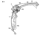
図2は枠体組立16の斜視図、図3は枠体組立16の断面図である。
図2では、前部エアフィルタ17、上部エアフィルタ20、エアフィルタ清掃ユニットSを示しているが、空気清浄ユニット18は省略している。図3では、前部エアフィルタ17、上部エアフィルタ20、エアフィルタ清掃ユニットSおよび空気清浄ユニット収納部16aの概略の断面を示している。
枠体組立16の前面側開口部は、上記空気清浄ユニット18が取付けられる上記空気清浄ユニット収納部16aを構成し、さらにこの前面側に前部エアフィルタ17が取付けられるとともに、上部エアフィルタ20が移動して前部エアフィルタ17の前面側に延出可能な前面側エアフィルタ収納部16bを備えている。
FIG. 2 is a perspective view of the frame assembly 16, and FIG. 3 is a cross-sectional view of the frame assembly 16.
In FIG. 2, the front air filter 17, the upper air filter 20, and the air filter cleaning unit S are shown, but the air cleaning unit 18 is omitted. FIG. 3 shows a schematic cross section of the front air filter 17, the upper air filter 20, the air filter cleaning unit S, and the air cleaning unit storage portion 16 a.
The opening on the front surface side of the frame assembly 16 constitutes the air purification unit housing portion 16a to which the air purification unit 18 is attached. Further, the front air filter 17 is attached to the front surface side, and the upper air filter 20 is A front-side air filter housing portion 16 b that can move and extend to the front side of the front air filter 17 is provided.

枠体組立16の上面側には、上部エアフィルタ20が取付けられるとともに、前部エアフィルタ17が移動して上部エアフィルタ20の上面側に延出可能な上面側エアフィルタ収納部16cを備えている。
枠体組立16における前面側エアフィルタ収納部16bと上面側エアフィルタ収納部16cとの間は、上記エアフィルタ清掃ユニットSを着脱自在に装着するエアフィルタ清掃ユニット取付け部16dとなっている。
An upper air filter 20 is attached to the upper surface side of the frame assembly 16, and an upper air filter housing portion 16 c that can move to the upper surface side of the upper air filter 20 by moving the front air filter 17 is provided. Yes.
An air filter cleaning unit mounting portion 16d for detachably mounting the air filter cleaning unit S is provided between the front side air filter storage portion 16b and the upper surface side air filter storage portion 16c in the frame assembly 16.

後述するように、前部エアフィルタ17に対する自動清掃運転が行われない通常状態で、各前部エアフィルタ17の上端はエアフィルタ清掃ユニットS内に挿入し支持される。同様に、各上部エアフィルタ20に対する自動清掃運転が行われない通常状態で、上部エアフィルタ20の前端がエアフィルタ清掃ユニットS内に挿入し支持される。
上記室内機本体1の前面パネル2を開放すれば、各前、上部エアフィルタ17,20は前面側と上面側の各エアフィルタ収納部16b,16cから容易に着脱自在となっている。また、空気清浄ユニット18を構成する一対の電気集塵機22も空気清浄ユニット収納部16aから容易に着脱自在である。
As will be described later, the upper end of each front air filter 17 is inserted into the air filter cleaning unit S and supported in a normal state where the automatic cleaning operation for the front air filter 17 is not performed. Similarly, the front end of the upper air filter 20 is inserted into the air filter cleaning unit S and supported in a normal state in which the automatic cleaning operation for each upper air filter 20 is not performed.
If the front panel 2 of the indoor unit body 1 is opened, the front and upper air filters 17 and 20 can be easily detached from the front and upper air filter storage portions 16b and 16c. In addition, the pair of electrostatic precipitators 22 constituting the air cleaning unit 18 can be easily detached from the air cleaning unit storage portion 16a.

特に、図2に示すように、枠体組立16の一側部で、上記エアフィルタ清掃ユニットSと対向する部位には、上記エアフィルタ清掃ユニットSを駆動する駆動源および駆動機構と、後述するエアフィルタ移動機構55を駆動する駆動源および駆動機構を備えた駆動部25が取付けられる。
図4はエアフィルタ清掃ユニットSと、その近傍部位の縦断面図である。
上記エアフィルタ清掃ユニットSは、後述するように前部エアフィルタ17および上部エアフィルタ20に付着する塵埃を除去する回転ブラシ30と、この回転ブラシ30を内部に収容するとともに、回転ブラシ30が除去した塵埃を収集する塵埃受け通路31を備えたダストボックス32および、上記ダストボックス32下面の開口部33を開閉自在に閉塞するシール部材34とから構成される。
In particular, as shown in FIG. 2, a drive source and a drive mechanism for driving the air filter cleaning unit S are provided at a portion facing one side of the frame assembly 16 and facing the air filter cleaning unit S, as will be described later. A drive source 25 that drives the air filter moving mechanism 55 and a drive unit 25 that includes the drive mechanism are attached.
FIG. 4 is a longitudinal sectional view of the air filter cleaning unit S and the vicinity thereof.
As will be described later, the air filter cleaning unit S includes a rotary brush 30 that removes dust adhering to the front air filter 17 and the upper air filter 20, and accommodates the rotary brush 30 therein, and the rotary brush 30 removes the dust. The dust box 32 is provided with a dust receiving passage 31 for collecting the collected dust, and the sealing member 34 is configured to close the opening 33 on the lower surface of the dust box 32 so as to be freely opened and closed.

上記ダストボックス32における開口部33から回転ブラシ30の一部が露出する。また、上記回転ブラシ30は通過してくる前部エアフィルタ17と上部エアフィルタ20のメッシュ部面と確実に接触するように組立てられる。
上記塵埃受け通路31は、回転ブラシ30の側部に、かつ回転ブラシ30の軸方向に沿って形成されるダストボックス32内の空間部であり、回転ブラシ30の周面一部が露出する開口部33以外は全て閉塞される。塵埃受け通路31は、回転ブラシ30の軸心よりも下側に通路面を構成していて、塵埃を確実に受けられる。
A part of the rotating brush 30 is exposed from the opening 33 in the dust box 32. Further, the rotating brush 30 is assembled so as to be surely in contact with the front air filter 17 and the mesh surface of the upper air filter 20 passing therethrough.
The dust receiving passage 31 is a space in the dust box 32 formed on the side of the rotating brush 30 and along the axial direction of the rotating brush 30, and an opening in which a part of the peripheral surface of the rotating brush 30 is exposed. All except 33 are blocked. The dust receiving passage 31 forms a passage surface below the axis of the rotating brush 30 and can reliably receive dust.

上記シール部材34は、たとえば合成ゴムなどの柔軟な弾性材から形成され、後述するリフト機構45に支持される。通常は、開口部33から露出する回転ブラシ30部分に接触しない位置にあり、リフト機構45が作動しシール部材34を上昇駆動することで開口部33を閉塞できる。
ダストボックス32内部で、上記塵埃受け通路31と回転ブラシ30の収容部位との間には掻き落し用突部35が突設される。この掻き落し用突部35は常時、回転ブラシ30の毛先内に、回転ブラシ30の軸方向に亘って挿入し、回転ブラシ30の回転にともなって毛先が摺接する位置にある。
The seal member 34 is formed of a flexible elastic material such as synthetic rubber, and is supported by a lift mechanism 45 described later. Usually, it is in a position where it does not come into contact with the portion of the rotating brush 30 exposed from the opening 33, and the opening 33 can be closed by operating the lift mechanism 45 and driving the seal member 34 upward.
Inside the dust box 32, a scraping protrusion 35 is provided between the dust receiving passage 31 and the portion where the rotary brush 30 is accommodated. The scraping projection 35 is always inserted into the bristles of the rotary brush 30 along the axial direction of the rotary brush 30 and is in a position where the bristles are in sliding contact with the rotation of the rotary brush 30.

図5(A)は室内機本体1に組み込まれたエアフィルタ清掃ユニットSを構成するダストボックス32の一側部(正面視で右側部)斜視図、図5(B)は枠体組立16に取付けられたダストボックス32の他側部(正面視で左側部)斜視図である。
上記ダストボックス32の左右両側部には、把手部38が一体に設けられている。ダストボックス32を枠体組立16のエアフィルタ清掃ユニット取付け部16dに取付け、もしくはここから取外しする際は、上記把手部38を持って作業すると容易に行える。
5A is a perspective view of one side portion (right side portion in front view) of the dust box 32 constituting the air filter cleaning unit S incorporated in the indoor unit main body 1, and FIG. 5B is attached to the frame assembly 16. It is the other side part (left side part by front view) perspective view of the obtained dust box 32. FIG.
On both the left and right sides of the dust box 32, handle portions 38 are integrally provided. When the dust box 32 is attached to or removed from the air filter cleaning unit attachment portion 16d of the frame assembly 16, it can be easily performed by holding the handle portion 38.

図5(A)に示すように、上記ダストボックス32の一側部で、この上面をなすボックスカバー32bには矩形状の空気導入孔39が設けられている。この空気導入孔39は、上記塵埃受け通路31と対向して設けられていて、互いに連通する位置にある。
図5(B)に示すように、ダストボックス32の他側部には塵埃排出カバー40が一体に取付けられる。この塵埃排出カバー40は、塵埃受け通路31を介して上記空気導入孔39と連通する。エアフィルタ清掃ユニットSを枠体組立16に取付けた状態で、塵埃排出カバー40は枠体組立16に設けられる排出ボックス41内に収容されるようになっている。
As shown in FIG. 5 (A), a rectangular air introduction hole 39 is provided in the box cover 32b that forms the upper surface of one side of the dust box 32. As shown in FIG. The air introduction hole 39 is provided so as to face the dust receiving passage 31 and communicate with each other.
As shown in FIG. 5B, a dust discharge cover 40 is integrally attached to the other side of the dust box 32. The dust discharge cover 40 communicates with the air introduction hole 39 through the dust receiving passage 31. With the air filter cleaning unit S attached to the frame assembly 16, the dust discharge cover 40 is accommodated in a discharge box 41 provided in the frame assembly 16.

上記排出ボックス41は後述する(図8に示す)ように、接続ホース42を介して吸排気装置11と連通する。したがって、ダストボックス32内に形成される塵埃受け通路31の一端部は空気導入孔39を介してダストボックス32外部であるエアフィルタ清掃ユニットS外部と連通し、塵埃受け通路31の他端部は塵埃排出カバー40と排出ボックス41および接続ホース42を介して吸排気装置11と連通することになる。
このようにして構成されるダストボックス32は、帯電防止樹脂材を用いて成形され、かつ抗菌処理が施されている。そのため、塵埃の付着やカビの発生を防止して、長期に亘って清潔な状態を維持できる。同様に、回転ブラシ30についても抗菌処理したものを使用して、塵埃の付着やカビの発生を防止して、長期に亘って清潔な状態を維持できる。
As will be described later (shown in FIG. 8), the discharge box 41 communicates with the intake / exhaust device 11 via a connection hose 42. Therefore, one end portion of the dust receiving passage 31 formed in the dust box 32 communicates with the outside of the air filter cleaning unit S outside the dust box 32 through the air introduction hole 39, and the other end portion of the dust receiving passage 31 is dust discharge. The intake / exhaust device 11 communicates with the cover 40 via the discharge box 41 and the connection hose 42.
The dust box 32 thus configured is molded using an antistatic resin material and is subjected to antibacterial treatment. Therefore, it is possible to prevent the adhesion of dust and the generation of mold and maintain a clean state for a long time. Similarly, the antibacterial treatment of the rotating brush 30 can be used to prevent adhesion of dust and generation of mold and maintain a clean state for a long time.

さらに、ダストボックス32内部において塵埃の移動がスムーズとなるよう、塵埃接触部分に対して滑らかな表面処理を施している。特に塵埃受け通路31においては、断面積を略全域に亘り推力直径が12mm以上となるよう設計されており、実際の塵埃除去運転において圧損を小さく抑え、風の流れがスムーズになるよう構成される。塵埃受け通路31内の稜線は風上側にR2mm以上の曲面を形成することで、塵埃が引っ掛って移動しない等の不具合の発生を確実に防止できる。   Further, a smooth surface treatment is applied to the dust contact portion so that the movement of the dust within the dust box 32 is smooth. In particular, the dust receiving passage 31 is designed to have a thrust diameter of 12 mm or more over substantially the entire cross-sectional area, and is configured to suppress the pressure loss in the actual dust removal operation and smooth the wind flow. . By forming a curved surface of R2 mm or more on the windward side of the ridge line in the dust receiving passage 31, it is possible to reliably prevent the occurrence of problems such as dust being caught and not moving.

図5(A)に示す(図2にも示している)ように、上記駆動部25は、4個の駆動源である第1〜第4の駆動モータ46〜49と、これら駆動モータ46〜49を側面部に取付け、内部に後述するギヤ列を収容するケーシング51を備えたギヤ組立Gとから構成される。
上記第1の駆動モータ46および第2の駆動モータ47は、図1に示すように、前部エアフィルタ17を移動する前部移動機構52および上部エアフィルタ20を移動する上部移動機構53の駆動源であり、これら前部移動機構52と上部移動機構53とで上記フィルタ移動機構55が構成される。
As shown in FIG. 5A (also shown in FIG. 2), the drive unit 25 includes first to fourth drive motors 46 to 49, which are four drive sources, and these drive motors 46 to 46. 49 is attached to the side surface part, and is comprised from the gear assembly G provided with the casing 51 which accommodates the gear train mentioned later inside.
As shown in FIG. 1, the first drive motor 46 and the second drive motor 47 drive the front moving mechanism 52 that moves the front air filter 17 and the upper moving mechanism 53 that moves the upper air filter 20. The filter moving mechanism 55 is configured by the front moving mechanism 52 and the upper moving mechanism 53.

上記前、上部移動機構52,53を駆動するのに必要なトルクを確保するには、本来、大型の駆動モータを1個用意すれば足りるが、大径寸法であるので電気部品箱および前面パネル2と干渉する。必要トルクの半分のトルクを備えた2個の小型駆動モータ46,47を用意して、取付けスペース上の不具合を解消している。
上記第3の駆動モータ48は、上記回転ブラシ30の回転駆動源である。第4の駆動モータ49は、第1、第2の駆動モータ46,47の駆動力を前部移動機構52もしくは上部移動機構53もしくは上記リフト機構45のいずれかに伝達するよう選択して切換える切換え機構61の駆動源である。
In order to secure the torque necessary for driving the upper moving mechanisms 52 and 53, it is originally sufficient to prepare one large drive motor. However, since it has a large diameter, the electric component box and the front panel 2 interferes. Two small drive motors 46 and 47 having half the required torque are prepared to eliminate the problem of the installation space.
The third drive motor 48 is a rotational drive source of the rotary brush 30. The fourth drive motor 49 is selectively switched to transmit the driving force of the first and second drive motors 46 and 47 to either the front moving mechanism 52 or the upper moving mechanism 53 or the lift mechanism 45. It is a drive source of the mechanism 61.

図6は上記ギヤ組立Gを構成するギヤ列の斜視図、図7は図6のケーシング51の側面部を省略してギヤ列の一部を示すとともに、上記シール部材34を支持するリフト機構45の一部斜視図である。
上記ケーシング51の右側隅部に所定間隔を存して、互いに同一ギヤ径の一対のギヤEが支持される。これらギヤEの軸部には先に説明した第1の駆動モータ46と第2の駆動モータ47の回転軸がケーシング51を介して挿入され、各駆動モータ46,47に上記ギヤEが嵌着固定される。
FIG. 6 is a perspective view of a gear train constituting the gear assembly G. FIG. 7 shows a part of the gear train with the side surface portion of the casing 51 of FIG. 6 omitted, and a lift mechanism 45 for supporting the seal member 34. FIG.
A pair of gears E having the same gear diameter are supported with a predetermined interval at the right corner of the casing 51. The shafts of the gears E are inserted with the rotation shafts of the first drive motor 46 and the second drive motor 47 described above through the casing 51, and the gears E are fitted to the drive motors 46 and 47, respectively. Fixed.

各ギヤEは、互いに図示しないギヤに噛合され、このギヤの裏面にギヤBが一体に設けられる。上記ギヤBは、隣接する大径のギヤAに噛合し、このギヤAと同軸に小径の上部用ギヤFuが設けられる。なお説明すると、ギヤAと上部用ギヤFuは同軸に設けられているけれども、ギヤAと上部用ギヤFuは互いに自由に回転自在となっている。
また、上記ケーシング51には、上記ギヤAと噛合するギヤCが支持される。このギヤCにはギヤDが常に噛合していて、ギヤDは切換え機構61を構成する駆動アーム64の先端に支持される。さらに、上記ギヤCを中心にして、上部用ギヤFuと対称の位置に前部用ギヤFfが支持される。この前部用ギヤFfは前部移動機構52を構成する支軸の端部に嵌着される。
Each gear E is meshed with a gear (not shown), and a gear B is integrally provided on the back surface of the gear. The gear B meshes with an adjacent large-diameter gear A, and a small-diameter upper gear Fu is provided coaxially with the gear A. In other words, the gear A and the upper gear Fu are provided coaxially, but the gear A and the upper gear Fu are freely rotatable with respect to each other.
The casing 51 supports a gear C that meshes with the gear A. The gear C is always meshed with the gear C, and the gear D is supported at the tip of the drive arm 64 constituting the switching mechanism 61. Further, the front gear Ff is supported at a position symmetrical to the upper gear Fu around the gear C. The front gear Ff is fitted to the end of the spindle that constitutes the front moving mechanism 52.

一方、ここでは図示しない上記第4の駆動モータ49の回転軸はケーシング51を介して内部に突出し、この回転軸に駆動レバー65の基端部が嵌着固定される。上記駆動レバー65は基端部から軸方向とは直交する方向に一体に延設される舌片部65aを備えていて、この舌片部65aの先端に上記駆動アーム64の基端部が回動自在に連結される。
これら第4の駆動モータ49、駆動レバー65、駆動アーム64、ギヤDで、上記切換え機構61が構成される。すなわち、上記第4の駆動モータ49の回転方向に応じて駆動レバー65と駆動アーム64が一体になって回動し、駆動アーム64先端のギヤDの位置が変動するよう構成される。
On the other hand, the rotation shaft of the fourth drive motor 49 (not shown) projects inward through the casing 51, and the base end portion of the drive lever 65 is fitted and fixed to the rotation shaft. The drive lever 65 includes a tongue piece 65a that is integrally extended from the base end in a direction orthogonal to the axial direction, and the base end of the drive arm 64 rotates at the tip of the tongue piece 65a. It is connected freely.
The fourth drive motor 49, the drive lever 65, the drive arm 64, and the gear D constitute the switching mechanism 61. That is, the drive lever 65 and the drive arm 64 are integrally rotated according to the rotation direction of the fourth drive motor 49, and the position of the gear D at the tip of the drive arm 64 is changed.

さらに、上記切換え機構61を構成する駆動アーム64の先端部とギヤDは、ギヤアーム66の下端部にピンを介して回動自在に支持される。上記ギヤアーム66は上端部が支軸部pを介してケーシング51に支持され、この支軸部pには上記ギヤCも支持されている。
上記ギヤアーム66はギヤCとともに上記支軸部p回りに回動自在であり、このギヤアーム66の下端部に上記ギヤDおよび駆動アーム64の先端部が回動自在に連結される。そのため、上記ギヤDはギヤアーム66の回動姿勢に係らず常にギヤCに噛合することとなる。
Further, the front end portion of the drive arm 64 and the gear D constituting the switching mechanism 61 are rotatably supported by the lower end portion of the gear arm 66 through a pin. The gear arm 66 is supported at its upper end portion by the casing 51 via a support shaft portion p, and the gear C is also supported by the support shaft portion p.
The gear arm 66 is rotatable around the support shaft portion p together with the gear C, and the gear D and the distal end portion of the drive arm 64 are rotatably connected to the lower end portion of the gear arm 66. For this reason, the gear D always meshes with the gear C regardless of the rotational posture of the gear arm 66.

第4の駆動モータ49が駆動レバー65を介して駆動アーム64を回動した状態で、駆動アーム64に連結されるギヤDはギヤCとの噛合状態を維持しつつ、ギヤDは上部用ギヤFuもしくは前部用ギヤFfのいずれかに噛合可能であり、もしくはいずれのギヤFu,Ffにも噛合しない位置を選択できるようになっている。
図6のみ示すように、上記ケーシング51の隅部にはマイクロスイッチ67が取付けられている。上記駆動アーム64は、回動変位した位置によっては上記マイクロスイッチ67の作動子67aに接触してオン状態となし、検知信号は図1に示す制御部(制御手段)Nに送られるようになっている。
While the fourth drive motor 49 rotates the drive arm 64 via the drive lever 65, the gear D connected to the drive arm 64 maintains the meshed state with the gear C, while the gear D is the upper gear. It is possible to select a position that can mesh with either the Fu or the front gear Ff, or that does not mesh with any of the gears Fu and Ff.
As shown only in FIG. 6, micro switches 67 are attached to the corners of the casing 51. Depending on the rotationally displaced position of the driving arm 64, the driving arm 64 comes into contact with the actuator 67a of the micro switch 67 to be turned on, and a detection signal is sent to the control unit (control means) N shown in FIG. ing.

すなわち、駆動アーム64がマイクロスイッチ67をオン状態となすのは、駆動アーム64に支持されるギヤDが上部用ギヤFuもしくは前部用ギヤFfのいずれにも噛合しない位置にある。換言すれば,マイクロスイッチ67がオフ状態にあれば、ギヤDが上部用ギヤFuもしくは前部用ギヤFfのいずれかに噛合する位置にある。
上記切換え機構61を構成するギヤアーム66はまた、上記シール部材34を支持するリフト機構45も兼用する。図7のみに示すように、ギヤアーム66の下端部は支軸部pを中心として所定の曲率半径を形成していて、この内面側には内歯部68が設けられている。上記内歯部68にはリフト用ギヤ69が噛合し、このリフト用ギヤ69はケーシング51側面を貫通して設けられるシール用支軸70の端部に嵌着固定される。
That is, the drive arm 64 turns on the micro switch 67 at a position where the gear D supported by the drive arm 64 does not mesh with either the upper gear Fu or the front gear Ff. In other words, when the micro switch 67 is in the OFF state, the gear D is in a position where it meshes with either the upper gear Fu or the front gear Ff.
The gear arm 66 constituting the switching mechanism 61 also serves as a lift mechanism 45 that supports the seal member 34. As shown only in FIG. 7, the lower end portion of the gear arm 66 forms a predetermined radius of curvature around the support shaft portion p, and an inner tooth portion 68 is provided on the inner surface side. A lift gear 69 meshes with the internal tooth portion 68, and the lift gear 69 is fitted and fixed to an end portion of a seal support shaft 70 that penetrates the side surface of the casing 51.

上記シール用支軸70は、上記枠体組立16に取付けられる軸受具に支持され、上記シール部材34の下面側に、かつシール部材34の長手方向に沿って対向して設けられている。したがって、上記切換え機構61を構成する第4の駆動モータ49が駆動して、駆動レバー65と駆動アーム64を介してギヤアーム66を回動すれば、上記リフト用ギヤ69もまた回転することとなる。
上記シール用支軸70の所定部位にはシール駆動用カム71が設けられている。このシール駆動用カム71は全体的に円筒状をなし、周面一部に径方向に突出する半円板状のカム部qを備えている。
The seal support shaft 70 is supported by a bearing tool attached to the frame assembly 16 and is provided on the lower surface side of the seal member 34 and facing the longitudinal direction of the seal member 34. Therefore, when the fourth drive motor 49 constituting the switching mechanism 61 is driven to rotate the gear arm 66 via the drive lever 65 and the drive arm 64, the lift gear 69 also rotates. .
A seal drive cam 71 is provided at a predetermined portion of the seal support shaft 70. The seal drive cam 71 is generally cylindrical and includes a semi-disc-shaped cam portion q projecting in the radial direction at a part of the peripheral surface.

一方、上記シール部材34はシールベース73に取付けられていて、上記シールベース73はいわゆるパンタグラフ構造をなすシールガイド機構74に支持される。上記シールガイド機構74は枠体組立16に設けられ、リフト力のかからない通常の姿勢では平坦状に折り畳まれ、上方へのリフト力がかかった状態で立ち上り変形してシールベース73とともにシール部材34を上方へ押上げる作用をなす。
このようなシールガイド機構74の一部に、上記シール駆動用カム71が接離自在となるよう構成されている。シール駆動用カム71がシールガイド機構74の一部に接触した状態で、シールガイド機構74は立ち上り動作をなしてシール部材34は押上げられ、シール駆動用カム71がシールガイド機構74から離間すると、シールガイド機構74は自然的に平坦状に折り畳まれシール部材34は下降する。
On the other hand, the seal member 34 is attached to a seal base 73, and the seal base 73 is supported by a seal guide mechanism 74 having a so-called pantograph structure. The seal guide mechanism 74 is provided in the frame assembly 16 and is folded in a flat shape in a normal posture where no lift force is applied. The seal guide mechanism 74 rises and deforms in a state where the lift force is applied upward, and the seal member 34 is moved together with the seal base 73. Pushes upward.
The seal driving cam 71 is configured to be able to contact and separate from a part of such a seal guide mechanism 74. When the seal drive cam 71 is in contact with a part of the seal guide mechanism 74, the seal guide mechanism 74 starts up, the seal member 34 is pushed up, and the seal drive cam 71 is separated from the seal guide mechanism 74. The seal guide mechanism 74 is naturally folded into a flat shape, and the seal member 34 is lowered.

これらギヤアーム66、リフト用ギヤ69、シール駆動用カム71、シールガイド機構74で、シール部材34に対する上記リフト機構45が構成される。
つぎに、上記前部移動機構52および上部移動機構53について説明する。
再び図4に示すように、上記ダストボックス32の開口部33を開閉するシール部材34の両側部に沿って一対の支軸75a,75bが並行して設けられる。それぞれの支軸75a,75bの一端部(右側端部)には、上記ギヤ組立Gを構成する前部用ギヤFfもしくは上部用ギヤFuが嵌着固定される。実際には、支軸75aに前部用ギヤFfが取付けられ、支軸75bに上部用ギヤFuが取付けられる。
The gear mechanism 66, the lift gear 69, the seal drive cam 71, and the seal guide mechanism 74 constitute the lift mechanism 45 for the seal member 34.
Next, the front moving mechanism 52 and the upper moving mechanism 53 will be described.
As shown in FIG. 4 again, a pair of support shafts 75a and 75b are provided in parallel along both sides of the seal member 34 that opens and closes the opening 33 of the dust box 32. The front gear Ff or the upper gear Fu constituting the gear assembly G is fitted and fixed to one end portion (right end portion) of each of the support shafts 75a and 75b. Actually, the front gear Ff is attached to the support shaft 75a, and the upper gear Fu is attached to the support shaft 75b.

上記各支軸75a,75bの他端部(左側端部)は、軸受具を介して枠体組立16に回転自在に支持される。また、支軸75a,75bの中間部で、かつ前、上部エアフィルタ17,20の中央補強桟と対向する部位には、前部エアフィルタ駆動ギヤ76もしくは上部エアフィルタ駆動ギヤ77が嵌着固定される。これら前、上部エアフィルタ駆動ギヤ76,77の一部は、上記枠体組立16に設けられる開口部から前面側もしくは上面側へ突出する。
その一方で、上記前、上部エアフィルタ17,20の中央補強桟裏面には長手方向に沿って、いわゆるラック(平歯車)78が設けられている。それぞれのラック78には、枠体組立16から突出する前、上部エアフィルタ駆動ギヤ76,77が、いわゆるピニオンとして噛合する。
The other end portions (left end portions) of the support shafts 75a and 75b are rotatably supported by the frame assembly 16 via bearings. Further, the front air filter drive gear 76 or the upper air filter drive gear 77 is fitted and fixed at the intermediate portion of the support shafts 75a and 75b and at the front and the portion facing the central reinforcing bar of the upper air filters 17 and 20. Is done. Before these, a part of upper air filter drive gear 76,77 protrudes from the opening part provided in the said frame assembly 16 to the front side or upper surface side.
On the other hand, a so-called rack (spur gear) 78 is provided along the longitudinal direction on the back surfaces of the central reinforcing bars of the upper air filters 17 and 20. The upper air filter drive gears 76 and 77 mesh with each rack 78 as a so-called pinion before protruding from the frame assembly 16.

上記前部用ギヤFfが回転すれば、支軸75aに設けられる前部エアフィルタ駆動ギヤ76が回転し、ピニオンとラックの関係から前部エアフィルタ17が前部エアフィルタ駆動ギヤ76の回転方向に移動付勢される。また、上部用ギヤFuが回転すれば、支軸75bに設けられる上部エアフィルタ駆動ギヤ77が回転し、ピニオンとラックの関係から上部エアフィルタ20が上部エアフィルタ駆動ギヤ77の回転方向に移動付勢される。
このようにして、前部エアフィルタ駆動ギヤ76と前部エアフィルタ17に設けられるラック78とで、前部エアフィルタ17を移動する前部移動機構52が構成される。そして、上部エアフィルタ駆動ギヤ77と上部エアフィルタ20に設けられるラック78とで、上部エアフィルタ20を移動する上部移動機構53が構成される。
When the front gear Ff rotates, the front air filter drive gear 76 provided on the support shaft 75a rotates, and the front air filter 17 rotates in the rotational direction of the front air filter drive gear 76 due to the relationship between the pinion and the rack. Is energized to move. When the upper gear Fu rotates, the upper air filter drive gear 77 provided on the support shaft 75b rotates, and the upper air filter 20 is moved in the rotational direction of the upper air filter drive gear 77 due to the relationship between the pinion and the rack. Be forced.
In this way, the front air filter drive gear 76 and the rack 78 provided on the front air filter 17 constitute a front moving mechanism 52 that moves the front air filter 17. The upper air filter drive gear 77 and the rack 78 provided on the upper air filter 20 constitute an upper moving mechanism 53 that moves the upper air filter 20.

図8は、エアフィルタ清掃ユニットSと吸排気装置11との接続構造を説明する斜視図である。
上記吸排気装置11は、本来、室内空気を室内機本体1内に取入れたあと、熱交換器8の一次側もしくは二次側の空気を外部に排出する換気機能を備えているが、ここでは併せて、後述するように前部エアフィルタ17と上部エアフィルタ20からエアフィルタ清掃ユニットSが収集した塵埃を吸気し、かつ屋外へ排出する吸排気機能を備えている。
先に図5(B)で説明したように、エアフィルタ清掃ユニットSを構成するダストボックス32には、側端部に塵埃排出カバー40が取付けられていて、エアフィルタ清掃ユニットSを枠体組立16に取付けた状態で、枠体組立16に設けられる排出ボックス41内に収容される。
FIG. 8 is a perspective view illustrating a connection structure between the air filter cleaning unit S and the intake / exhaust device 11.
The intake / exhaust device 11 originally has a ventilation function for discharging the air on the primary side or the secondary side of the heat exchanger 8 to the outside after taking indoor air into the indoor unit body 1. In addition, as will be described later, it has an intake / exhaust function for sucking dust collected by the air filter cleaning unit S from the front air filter 17 and the upper air filter 20 and discharging it to the outdoors.
As described above with reference to FIG. 5 (B), the dust box 32 constituting the air filter cleaning unit S is provided with the dust discharge cover 40 at the side end, and the air filter cleaning unit S is attached to the frame assembly 16. In a state of being attached to the frame assembly 16, it is accommodated in a discharge box 41 provided in the frame assembly 16.

図8に示すように、上記排出ボックス41にはホース接続口41aが一体に設けられていて、接続ホース42の一端部が接続される。接続ホース42は緩やかな曲線をなすよう曲成されて、上記吸排気装置11に設けられる接続口91に接続される。すなわち、接続ホース42内には前、上部エアフィルタ17,20から除去した塵埃が流通するので、途中で詰まらないように配慮される。
吸排気装置11を構成するファンケーシング90には塵埃案内用ケース95が取付けられている。上記接続口91に接続される接続ホース42を介してエアフィルタ清掃ユニットSと吸排気装置11のファンケーシング90内とが連通する。上記塵埃案内用ケース95内には風力ダンパが設けられていて、塵埃はこの風力ダンパを介して吸排気装置11のファンケーシング90に導入される。
As shown in FIG. 8, the discharge box 41 is integrally provided with a hose connection port 41a, and one end of the connection hose 42 is connected thereto. The connection hose 42 is bent so as to form a gentle curve, and is connected to a connection port 91 provided in the intake / exhaust device 11. That is, since the dust removed from the upper air filters 17 and 20 circulates in the connection hose 42, it is considered not to be clogged in the middle.
A dust guide case 95 is attached to the fan casing 90 constituting the intake / exhaust device 11. The air filter cleaning unit S communicates with the inside of the fan casing 90 of the intake / exhaust device 11 through the connection hose 42 connected to the connection port 91. A wind damper is provided in the dust guiding case 95, and the dust is introduced into the fan casing 90 of the intake / exhaust device 11 through the wind damper.

接続ホース42に所定圧以上の風圧が加わると、風力ダンパは風圧で上方に押され、ファンケーシング90内部を開放するようになっている。また、この状態から所定圧以上の風圧が無くなれば、風力ダンパ96は再びファンケーシング90内部を閉成することとなる。
上記吸排気装置11は、ファンケーシング90の側面中心部に開口する換気吸込み口に設けられた開閉ダンパと、この開閉ダンパを駆動する機構およびファンケーシング90内に配置される換気ファンなどの送風機構から構成される。
When a wind pressure higher than a predetermined pressure is applied to the connection hose 42, the wind damper is pushed upward by the wind pressure to open the inside of the fan casing 90. If the wind pressure exceeding the predetermined pressure disappears from this state, the wind damper 96 closes the inside of the fan casing 90 again.
The intake / exhaust device 11 includes an opening / closing damper provided at a ventilation suction opening that opens at the center of the side surface of the fan casing 90, a mechanism for driving the opening / closing damper, and a ventilation mechanism such as a ventilation fan disposed in the fan casing 90. Consists of

リモコンに備えられる二次側換気モードボタンを押すと、熱交換器8を通過した熱交換器二次側空気を換気ファンに導く作用が行われる。一次側換気モードボタンを選択すると、前、上部エアフィルタ17,20を通過し熱交換器8に導かれる以前の熱交換器一次側空気を換気ファンに導く作用が行われる。全閉モードボタンを押すと、上記換気吸込み口を閉塞する作用が行われる。
上記ファンケーシング90は排気口90aを備えていて、この排気口90aには排気ダクトが接続される。上記排気ダクトは、室内機本体1の取付け壁面を貫通して屋外へ突出していて、吸排気装置11を構成する送風機構は排気ダクトを介して屋外と連通することになる。
When the secondary side ventilation mode button provided in the remote controller is pressed, the effect of guiding the heat exchanger secondary side air that has passed through the heat exchanger 8 to the ventilation fan is performed. When the primary side ventilation mode button is selected, the operation of leading the heat exchanger primary side air before passing through the upper air filters 17 and 20 to the heat exchanger 8 to the ventilation fan is performed. When the fully closed mode button is pressed, an action of closing the ventilation suction port is performed.
The fan casing 90 includes an exhaust port 90a, and an exhaust duct is connected to the exhaust port 90a. The exhaust duct penetrates the mounting wall surface of the indoor unit body 1 and protrudes outdoors, and the air blowing mechanism constituting the intake / exhaust device 11 communicates with the outdoors via the exhaust duct.

二次側換気モードもしくは一次側空気換気モードを選択し、ファンケーシング90の開閉ダンパを切換えて換気吸込み口を開口させ、ファンケーシング90内の換気ファンを回転駆動することで、熱交換器二次側空気もしくは熱交換器一次側空気が屋外へ排出される、いわゆる換気作用をなす。これら一次側と二次側の選択は、被空調室内の状態ばかりでなく室内機本体内の状態に応じて選択される。さらに、全閉モードを選択すると、換気吸込み口を開閉ダンパが閉塞する。
エアフィルタ清掃ユニットSと吸排気装置11を連通する接続ホース42は、ファンケーシング90の換気吸込み口と排気口90aとの間に設けられる塵埃案内用ケース95に接続されているため、換気吸込み口を閉塞して換気ファン99を回転駆動すれば、接続ホース42を介してエアフィルタ清掃ユニットS側に負圧がかかることとなる。
The secondary side ventilation mode or the primary side air ventilation mode is selected, the opening / closing damper of the fan casing 90 is switched to open the ventilation suction port, and the ventilation fan in the fan casing 90 is rotationally driven, whereby the heat exchanger secondary Side air or heat exchanger primary side air is discharged to the outside, so-called ventilation action. The selection of the primary side and the secondary side is selected according to the state in the indoor unit main body as well as the state in the air-conditioned room. Further, when the fully closed mode is selected, the open / close damper closes the ventilation suction port.
The connection hose 42 that communicates the air filter cleaning unit S and the intake / exhaust device 11 is connected to a dust guide case 95 provided between the ventilation intake port of the fan casing 90 and the exhaust port 90a. If the ventilation fan 99 is rotationally driven by closing the above, negative pressure is applied to the air filter cleaning unit S side via the connection hose 42.

再び図1に示す制御部Nは、上述した可動パネル2A、吹出しルーバー7a,7b、室内送風機10、吸排気装置11の換気ファン、空気清浄ユニット18、エアフィルタ清掃ユニットSおよびエアフィルタ移動機構55の駆動部25の駆動源と、図示しない室外機と電気的に接続されていて、図示しないリモコン(遠隔操作盤)からの指示信号に基づいて必要な制御をなす。
つぎに、このようにして構成される空気調和機室内機の作用について説明する。
使用者がリモコン(遠隔操作盤)の運転ボタンを押圧操作すると、制御部Nは室内送風機10を駆動するとともに空気清浄ユニット18を作用させる。さらに、室外機における圧縮機を駆動して冷凍サイクル運転を開始し、室内送風機10を回転駆動するとともに、吹出しルーバー7a,7bを所定の方向に回動変位させる。
The control unit N shown in FIG. 1 again includes the movable panel 2A, the blowout louvers 7a and 7b, the indoor blower 10, the ventilation fan of the intake / exhaust device 11, the air cleaning unit 18, the air filter cleaning unit S, and the air filter moving mechanism 55. The drive unit 25 is electrically connected to an outdoor unit (not shown) and performs necessary control based on an instruction signal from a remote controller (remote control panel) (not shown).
Next, the operation of the air conditioner indoor unit configured as described above will be described.
When the user presses the operation button on the remote control (remote control panel), the control unit N drives the indoor blower 10 and activates the air cleaning unit 18. Further, the compressor in the outdoor unit is driven to start the refrigeration cycle operation, the indoor blower 10 is rotationally driven, and the blowout louvers 7a and 7b are rotationally displaced in a predetermined direction.

室内空気は前面吸込み口4および上面吸込み口5から室内機本体1内に導かれ、前部エアフィルタ17および上部エアフィルタ20を通過する。このとき、室内空気中に含まれる塵埃が前部エアフィルタ17および上部エアフィルタ20に捕捉される。前部エアフィルタ17で塵埃が除去された室内空気は、空気清浄ユニット18を構成する一対の電気集塵機を通過して、より微細な塵埃が電気的に集塵され、かつ脱臭される。
清浄化した室内空気は熱交換器8を流通し、ここに導かれる冷媒と熱交換作用が行われる。そのあと、熱交換空気は吹出し通風路15に沿って導かれ、吹出し口6から吹出しルーバー7a,7bに案内されて室内へ吹出され、効率のよい空調運転を継続する。
The room air is guided into the indoor unit body 1 from the front suction port 4 and the upper suction port 5 and passes through the front air filter 17 and the upper air filter 20. At this time, dust contained in the room air is captured by the front air filter 17 and the upper air filter 20. The room air from which the dust has been removed by the front air filter 17 passes through a pair of electrostatic precipitators constituting the air cleaning unit 18, and finer dust is electrically collected and deodorized.
The cleaned indoor air flows through the heat exchanger 8 and performs a heat exchange action with the refrigerant led to the room air. After that, the heat exchange air is guided along the blowout ventilation path 15, guided from the blowout opening 6 to the blowout louvers 7a and 7b and blown into the room, and the efficient air conditioning operation is continued.

つぎに、前部エアフィルタ17と上部エアフィルタ20にて捕捉され付着している塵埃を自動的に除去する、エアフィルタ清掃モードについて説明する。
基本的には、制御部Nは室内送風機10の運転時間を積算していて、その運転時間の積算が予め設定された時間を経過し、かつリモコンからの空調運転停止指令を受信した後にエアフィルタ自動清掃が実施される。
このときは、上部移動機構53を駆動して上部エアフィルタ20を移動し、エアフィルタ清掃ユニットSに通過させて、上部エアフィルタ20に対する自動清掃を実施する。上部エアフィルタ20の清掃が終了したら、その回のエアフィルタ清掃モードも終了する。
Next, an air filter cleaning mode for automatically removing dust trapped and attached by the front air filter 17 and the upper air filter 20 will be described.
Basically, the control unit N accumulates the operation time of the indoor blower 10, the accumulation of the operation time has elapsed in advance, and the air filter after receiving the air conditioning operation stop command from the remote control Automatic cleaning is performed.
At this time, the upper moving mechanism 53 is driven to move the upper air filter 20 and pass through the air filter cleaning unit S, so that the upper air filter 20 is automatically cleaned. When the cleaning of the upper air filter 20 is completed, the air filter cleaning mode for that time is also ended.

そして、室内送風機10の運転時間を積算し、その運転時間の積算が予め設定された時間を経過し、かつリモコンからの空調運転停止指令を受信した後は、次回のエアフィルタ自動清掃が実施される。   Then, the operation time of the indoor blower 10 is integrated, and after the preset time has elapsed and the air conditioning operation stop command is received from the remote controller, the next automatic air filter cleaning is performed. The

このときは、始めに上部移動機構53を駆動して上部エアフィルタ20を移動し、エアフィルタ清掃ユニットSに通過させて上部エアフィルタ20に対する自動清掃を実施する。そのあと、前部移動機構52を駆動して前部エアフィルタ17を移動し、エアフィルタ清掃ユニットSに通過させて前部エアフィルタ17に対する自動清掃を実施する。前部エアフィルタ17の清掃が終了したら、エアフィルタ清掃モードも終了する。
このようにしてエアフィルタ自動掃除の制御は、室内送風機10の運転時間を積算し、予め設定された運転積算時間が経過する毎に、上部エアフィルタ20のみに対する自動清掃と、上部エアフィルタ20を自動清掃してから前部エアフィルタ17を自動清掃する操作を繰り返して行う。
At this time, first, the upper moving mechanism 53 is driven to move the upper air filter 20, and the air filter cleaning unit S is passed through to automatically clean the upper air filter 20. Thereafter, the front moving mechanism 52 is driven to move the front air filter 17, and the front air filter 17 is passed through the air filter cleaning unit S to automatically clean the front air filter 17. When the cleaning of the front air filter 17 is finished, the air filter cleaning mode is also finished.
In this way, the control of the air filter automatic cleaning is performed by accumulating the operation time of the indoor blower 10 and automatically cleaning only the upper air filter 20 and the upper air filter 20 each time a preset operation integration time elapses. After the automatic cleaning, the operation of automatically cleaning the front air filter 17 is repeated.

すなわち、空気調和機を運転している場合は、前部エアフィルタ17と上部エアフィルタ20の全面的に塵埃がほぼ均等に付着して堆積する。しかしながら、空気調和機の運転を停止し、使用しない期間においては、室内機本体1の前面側よりも上面(天面)側に塵埃が堆積し易くなる。
そのため、まず塵埃が堆積し易い上部エアフィルタ20の自動清掃を実施し、次回の室内送風機10の運転積算時間経過後に、上部エアフィルタ20と前部エアフィルタ17を自動清掃を実施する。
That is, when the air conditioner is operating, dust is deposited almost uniformly on the entire surface of the front air filter 17 and the upper air filter 20. However, during the period when the operation of the air conditioner is stopped and not used, dust tends to accumulate on the upper surface (top surface) side rather than the front surface side of the indoor unit body 1.
Therefore, first, the upper air filter 20 in which dust easily accumulates is automatically cleaned, and the upper air filter 20 and the front air filter 17 are automatically cleaned after the next accumulated operation time of the indoor fan 10.

すなわち、エアフィルタを上部エアフィルタ20と前部エアフィルタ17の複数の掃除面に分割し、各掃除面を個別に清掃可能なエアフィルタ清掃手段Sにより、それぞれのエアフィルタ20,17の掃除を空気調和機の所定運転時間経過後毎に実施することで、塵埃の堆積度合いに応じて各掃除面のエアフィルタ清掃周期を異ならせるようにした。これにより、エアフィルタ清掃の空運転が無くなり、無駄を防止できるとともに、各エアフィルタ20,17全面が常時クリーンな状態となり、冷暖性能の初期状態を略保持できる。   That is, the air filter is divided into a plurality of cleaning surfaces of the upper air filter 20 and the front air filter 17, and the air filters 20 and 17 are cleaned by the air filter cleaning means S that can individually clean each cleaning surface. By carrying out each time after the predetermined operation time of the air conditioner has elapsed, the air filter cleaning cycle of each cleaning surface is made different according to the degree of dust accumulation. As a result, there is no idle operation for air filter cleaning, waste can be prevented, and the entire surfaces of the air filters 20, 17 are always in a clean state, so that the initial state of the cooling / heating performance can be substantially maintained.

なお、室内送風機10の運転時間積算は、空気調和機に対する運転モードの設定の影響を受ける。すなわち、運転モードが変れば室内送風機10の回転数が相違し、その結果、吹出し風量に差が生じる。さらに、吹出し口6において熱交換空気の風向を調節するルーバー7a,7bの角度も相違して、居住空間床面への熱交換空気の流れ方が変化する。
たとえば、冷房運転を選択すると、冷気が直接居住人に当たらないように吹出し方向は略水平方向に向けられる。この場合、熱交換空気は居住空間の天井側において対流となるので、塵埃は居住人の移動によって生じるものがほとんどであり、前、上部エアフィルタ17,20に付着する量は極く少ない。
In addition, the operation time integration of the indoor fan 10 is affected by the setting of the operation mode for the air conditioner. That is, if the operation mode changes, the rotation speed of the indoor blower 10 is different, and as a result, a difference occurs in the blown-out air volume. Furthermore, the angle of the louvers 7a and 7b for adjusting the air direction of the heat exchange air at the outlet 6 is also different, and the way in which the heat exchange air flows to the floor space of the living space changes.
For example, when the cooling operation is selected, the blowing direction is directed to a substantially horizontal direction so that the cool air does not directly hit the resident. In this case, since the heat exchange air is convection on the ceiling side of the living space, most dust is generated by the movement of the resident, and the amount of dust adhering to the upper air filters 17 and 20 is extremely small.

暖房運転を行うと、熱交換空気(暖気)は冷房時の冷気と違って空気密度が低いため、居住人の足元を暖める下向きの風向に調節される。このときは、前、上部エアフィルタ17,20に付着する塵埃は居住人の移動によって生じるものと、暖房運転によって生じるものがあり、冷房時と比較して各フィルタ17,20への塵埃付着量が多くなる。
そのため、運転モードに応じてエアフィルタ自動清掃を開始するための室内送風機10の運転積算時間に重み付け(係数を付与)をする。たとえば、冷房運転モードが選択された場合にα=1.0と設定し、除湿運転モードが選択された場合はα=1.1に設定し、暖房運転モードが選択された場合はα=0.8に設定する。
When heating operation is performed, the heat exchange air (warm air) is adjusted to a downward wind direction that warms the feet of the resident because the air density is low unlike the cold air during cooling. At this time, the dust adhering to the upper air filters 17 and 20 may be generated by the movement of the occupant or may be generated by the heating operation. The amount of dust adhering to the filters 17 and 20 is compared with that during cooling. Will increase.
For this reason, the operation integration time of the indoor blower 10 for starting the air filter automatic cleaning is weighted (a coefficient is given) according to the operation mode. For example, α = 1.0 is set when the cooling operation mode is selected, α = 1.1 is set when the dehumidification operation mode is selected, and α = 0 when the heating operation mode is selected. Set to .8.

これによって、冷房運転時期と、暖房運転時期とに係らず、常に最適な積算時間にて、上部エアフィルタ20と前部エアフィルタ17に対する自動清掃をなす。具体的には、各エアフィルタ20,17の移動開始時間と、エアフィルタ清掃ユニットS内の回転ブラシ30の駆動開始時間に時間差を設ける。そして、各エアフィルタ20,17の移動終了時間と回転ブラシ30の駆動終了時間に時間差を設けて、回転ブラシ30の空運転を防止する。
なお、リモコンから任意の時間にフィルタ自動掃除モードの信号を受信した場合、すなわち手動運転モードが選択された場合は、制御部Nは室内送風機10の運転時間の積算に拘わらず、常に上部エアフィルタ20および前部エアフィルタ17の両方に対する全面自動掃除を実施するよう設定されている。
As a result, the upper air filter 20 and the front air filter 17 are automatically cleaned at an optimal integration time regardless of the cooling operation time and the heating operation time. Specifically, a time difference is provided between the movement start time of the air filters 20 and 17 and the drive start time of the rotary brush 30 in the air filter cleaning unit S. Then, a time difference is provided between the movement end time of each air filter 20, 17 and the drive end time of the rotary brush 30 to prevent the idling operation of the rotary brush 30.
Note that when the filter automatic cleaning mode signal is received from the remote controller at an arbitrary time, that is, when the manual operation mode is selected, the control unit N always maintains the upper air filter regardless of the accumulated operation time of the indoor blower 10. It is set so that the entire surface of both the front air filter 17 and the front air filter 17 is automatically cleaned.

以下に、実際のエアフィルタ清掃に係るフローチャートを図10から図11と図12の順に亘って説明する。この説明には、上述した図1から図8および、図9(A)から図9(C)で示すギヤ組立Gの作用説明も併せて行う必要がある。
図10において、最初はシール駆動部のチェック工程が行われる。具体的には、エアフィルタ清掃ユニットSを構成するシール部材34と、ダストボックス32に設けられる開口部33との関係がチェックされる。
Below, the flowchart which concerns on actual air filter cleaning is demonstrated over the order of FIGS. 10-11 and FIG. In this description, it is necessary to also explain the operation of the gear assembly G shown in FIGS. 1 to 8 and FIGS. 9 (A) to 9 (C).
In FIG. 10, first, a check process of the seal driving unit is performed. Specifically, the relationship between the seal member 34 constituting the air filter cleaning unit S and the opening 33 provided in the dust box 32 is checked.

スタートからステップT1で、停止ボタンが押され空調運転を停止しているうえに、前回のエアフィルタに対する自動掃除から所定時間が経過しているか、もしくはリモコンの手動クリーニングボタンが押圧操作され信号が制御部Nに送られることで、エアフィルタの掃除動作が開始される。
ステップT2で、吸排気装置11に備えられる開閉ダンパを駆動して吸気口を閉じ、塵埃排出モードとする。すなわち、制御部Nは吸排気装置11に対して開閉ダンパの全閉モードを指示する。
In step T1 from the start, the stop button is pressed to stop the air conditioning operation, and a predetermined time has elapsed since the previous automatic cleaning of the air filter, or the manual cleaning button on the remote control is pressed to control the signal By being sent to the part N, the air filter cleaning operation is started.
In step T2, the open / close damper provided in the intake / exhaust device 11 is driven to close the intake port to enter the dust discharge mode. That is, the controller N instructs the intake / exhaust device 11 to enter the fully closed mode of the open / close damper.

ステップT3で、切換え機構61を前部エアフィルタ17側へ動かす。具体的には、前回のエアフィルタ自動掃除モードで切換え機構61は上部エアフィルタ20側である、図9(B)に示すようにギヤDが上部用ギヤFuに噛合して終了している。
上記制御部Nは、第4の駆動モータ49に駆動信号を送って駆動レバー65を介して駆動アーム64を回動変位させる。駆動アーム64に設けられるギヤDは上部用ギヤFuとの噛合位置から、図9(C)に示すようにギヤDがギヤCのみに噛合する位置に変り、さらに図9(A)に示すようにギヤDが前部用ギヤFfに噛合する位置に変って停止する。
In step T3, the switching mechanism 61 is moved to the front air filter 17 side. Specifically, in the previous air filter automatic cleaning mode, the switching mechanism 61 is on the upper air filter 20 side, and the gear D is engaged with the upper gear Fu as shown in FIG.
The control unit N sends a drive signal to the fourth drive motor 49 to rotate and displace the drive arm 64 via the drive lever 65. The gear D provided on the drive arm 64 changes from a meshing position with the upper gear Fu to a position where the gear D meshes only with the gear C as shown in FIG. 9C, and further as shown in FIG. 9A. Then, the gear D changes to a position where it engages with the front gear Ff and stops.

このような駆動アーム64の作動にともない、駆動アーム64の一部は上記マイクロスイッチ67の作動子67aと接触し、もしくは離間する。はじめの図9(B)の状態では駆動アーム64はマイクロスイッチ67の作動子67aと離間してOFF。次の図9(C)の状態では駆動アーム64は作動子67aに接触してON。つぎの図9(A)の状態では駆動アーム64は作動子67aに接触してOFFとなる。
ステップT4で、マイクロスイッチ67の入力がOFF−ON−OFFの順に繰り返えされたか否かが判断される。Yesである場合は、ステップT5に移って正常と判断される。すなわち、正常であれば図4に示すように、ダストボックス32内に前部エアフィルタ17と上部エアフィルタ20が存在せず開口部33は開放されていることになる。
Along with the operation of the drive arm 64, a part of the drive arm 64 comes into contact with or separates from the actuator 67 a of the microswitch 67. In the state shown in FIG. 9B, the driving arm 64 is separated from the actuator 67a of the micro switch 67 and is turned off. In the next state shown in FIG. 9C, the drive arm 64 comes into contact with the actuator 67a and is turned on. In the next state shown in FIG. 9A, the drive arm 64 comes into contact with the actuator 67a and is turned OFF.
In step T4, it is determined whether or not the input of the micro switch 67 is repeated in the order of OFF-ON-OFF. If yes, the process moves to step T5 and is determined to be normal. That is, if it is normal, as shown in FIG. 4, the front air filter 17 and the upper air filter 20 do not exist in the dust box 32 and the opening 33 is open.

ステップT4でNoである場合は、ダストボックス32の開口部33内に前部エアフィルタ17もしくは上部エアフィルタ20の一部が存在して、駆動アーム64がマイクロスイッチ作動子67aに接触できない。この場合は、ステップT6に移って異常を表示する。
このようにして、エアフィルタの自動清掃を実施する以前に、前部エアフィルタ17が枠体組立16の前面側エアフィルタ収納部16bに正しくセットされているか否かと、上部エアフィルタ20が上面側エアフィルタ収納部16cに正しくセットされているか否かをチェックする必要がある。
When No in step T4, a part of the front air filter 17 or the upper air filter 20 exists in the opening 33 of the dust box 32, and the drive arm 64 cannot contact the microswitch actuator 67a. In this case, the process proceeds to step T6 and an abnormality is displayed.
Thus, before carrying out the automatic cleaning of the air filter, whether or not the front air filter 17 is correctly set in the front side air filter storage portion 16b of the frame assembly 16 and whether the upper air filter 20 is on the upper side It is necessary to check whether the air filter storage unit 16c is correctly set.

以上でシール駆動部のチェック工程が終了し、つぎに上部エアフィルタ20に対する自動掃除の工程に移る。
ステップT7において、切換え機構61を上部エアフィルタ20側へ動かす。すなわち図9(B)に示すように、ギヤDを上部用ギヤFuに噛合させる。ステップT8に移って、切換え機構61を上部エアフィルタ20側へ付勢し続ける。ステップT9において、フィルタ駆動モータ46,47を駆動する。したがって、上部移動機構53が作動して上部エアフィルタ20を前部エアフィルタ17の前面側へ移動付勢する。
具体的には、第1、第2の駆動モータ46,47の駆動により一対のギヤEが互いに同方向に回転駆動される。これらギヤEを介してギヤBが回転し、このギヤBに噛合するギヤAからギヤCに回転力が伝達される。そして、ギヤCからギヤDを介して上部用ギヤFuに回転力が伝達され、この上部用ギヤFuを支持する支軸75bが回転する。
This completes the check process of the seal drive unit, and then proceeds to an automatic cleaning process for the upper air filter 20.
In step T7, the switching mechanism 61 is moved to the upper air filter 20 side. That is, as shown in FIG. 9B, the gear D is engaged with the upper gear Fu. Moving to step T8, the switching mechanism 61 is continuously urged toward the upper air filter 20 side. In step T9, the filter drive motors 46 and 47 are driven. Accordingly, the upper moving mechanism 53 operates to urge the upper air filter 20 to move to the front side of the front air filter 17.
Specifically, the pair of gears E are rotationally driven in the same direction by driving the first and second drive motors 46 and 47. The gear B rotates through the gear E, and the rotational force is transmitted from the gear A meshing with the gear B to the gear C. Then, the rotational force is transmitted from the gear C to the upper gear Fu via the gear D, and the support shaft 75b that supports the upper gear Fu rotates.

上記支軸75bには上部エアフィルタ駆動ギヤ77が設けられ、しかも上部エアフィルタ20が上面側から押え付けられて中央補強桟のラックと噛合している。上部エアフィルタ駆動ギヤ77が回転すれば、上部エアフィルタ20は確実に移動を開始し、徐々に上面側のエアフィルタ収納部16cから出て下降移動する。
このとき、リフト機構45を構成するシール駆動用カム71がシールガイド機構74から離間していて、シールガイド機構74は平坦状に折り畳まれ、シール部材34は下降位置にあり開口部33は開放されている。したがって、上部エアフィルタ20はダストボックス32下端とシール部材34との間に形成される隙間を挿通する。
The support shaft 75b is provided with an upper air filter drive gear 77, and the upper air filter 20 is pressed from the upper surface side and meshed with the rack of the central reinforcing bar. If the upper air filter drive gear 77 rotates, the upper air filter 20 starts to move reliably, and gradually moves down from the air filter housing portion 16c on the upper surface side.
At this time, the seal drive cam 71 constituting the lift mechanism 45 is separated from the seal guide mechanism 74, the seal guide mechanism 74 is folded flat, the seal member 34 is in the lowered position, and the opening 33 is opened. ing. Therefore, the upper air filter 20 is inserted through a gap formed between the lower end of the dust box 32 and the seal member 34.

ステップT10に移って、上部エアフィルタ20の移動開始後に回転ブラシ30を駆動する。すなわち、上部エアフィルタ20の移動と時間差をおいて回転ブラシ30が回転駆動されるよう設定されている。そのため、回転ブラシ30の毛先は上部エアフィルタ20のメッシュ部のみに接触し、枠体部に接触せずにすむ。
上部エアフィルタ20は前端から順次後端側に亘って回転ブラシ30に対向し、かつ摺接しながら下降移動する。上部エアフィルタ20に付着していた塵埃は、回転ブラシ30によって円滑に、かつ確実に掻き落されて除去される。塵埃は上部エアフィルタ20から回転ブラシ30に転移する。
Moving to step T10, the rotary brush 30 is driven after the upper air filter 20 starts moving. That is, the rotary brush 30 is set to be driven to rotate with a time difference from the movement of the upper air filter 20. Therefore, the bristles of the rotating brush 30 are in contact with only the mesh portion of the upper air filter 20 and do not need to be in contact with the frame portion.
The upper air filter 20 faces the rotating brush 30 sequentially from the front end to the rear end side, and moves downward while sliding. Dust adhering to the upper air filter 20 is smoothly and reliably scraped off and removed by the rotating brush 30. Dust is transferred from the upper air filter 20 to the rotating brush 30.

この直後に回転ブラシ30は掻き落し用突部35に接触して通過する。掻き落し用突部35が櫛歯状に形成されているので、回転ブラシ30に転移した塵埃は掻き落されて塵埃受け通路31に落下する。上記塵埃受け通路31は、回転ブラシ30と対向する部位が開口している以外は密閉構造となっているので、掻き落とされた塵埃が塵埃受け通路31から周辺へ飛散することはない。   Immediately after this, the rotating brush 30 passes in contact with the scraping projection 35. Since the scraping projection 35 is formed in a comb-like shape, the dust transferred to the rotary brush 30 is scraped off and falls into the dust receiving passage 31. Since the dust receiving passage 31 has a sealed structure except that a portion facing the rotating brush 30 is opened, the scraped dust does not scatter from the dust receiving passage 31 to the periphery.

上部エアフィルタ20は回転ブラシ30によって塵埃を除去されつつ、枠体組立16に設けられ前部エアフィルタ17を収納する前面側のエアフィルタ収納部16dに挿入される。すなわち、上部エアフィルタ20は前部エアフィルタ17の上部側に、互いに狭小の間隙を存して対向するよう案内される。
ステップT11に移って、上部エアフィルタ20の移動が完了した時点で、掃除用アクチュエータを微少時間停止する。具体的には、上部エアフィルタ20の後端が前面側のエアフィルタ収納部16dの上端に挿入したところで、制御部Nは第1、第2の駆動モータ46,47および回転ブラシ30の駆動を一旦停止するよう制御する。
The upper air filter 20 is inserted into a front-side air filter housing portion 16 d provided in the frame assembly 16 and housing the front air filter 17 while dust is removed by the rotating brush 30. That is, the upper air filter 20 is guided on the upper side of the front air filter 17 so as to face each other with a narrow gap therebetween.
Moving to Step T11, when the movement of the upper air filter 20 is completed, the cleaning actuator is stopped for a short time. Specifically, when the rear end of the upper air filter 20 is inserted into the upper end of the air filter housing portion 16d on the front side, the control unit N drives the first and second drive motors 46 and 47 and the rotary brush 30. Control to stop once.

ついで、ステップT12に移って回転ブラシ30を回転駆動し、ステップT12でフィルタ駆動モータを逆転駆動して上部エアフィルタ20を元の位置まで移動する。すなわち、上記制御部Nは、第1、第2の駆動モータ46,47に対して逆方向に回転する駆動信号を送る。
各ギヤは逆方向に回転して、上部移動機構53は上部エアフィルタ20を上昇移動させる。先の塵埃除去作用で全ての塵埃が上部エアフィルタ20から除去されているが、条件によっては、なお上部エアフィルタ20に塵埃が残留する場合がある。したがって、上部エアフィルタ20を上昇移動する際にも回転ブラシ30に摺接させるので、残留していた全ての塵埃は確実に除去される。
Next, the process proceeds to step T12, and the rotary brush 30 is rotationally driven. In step T12, the filter drive motor is driven in reverse to move the upper air filter 20 to the original position. That is, the control unit N sends a drive signal that rotates in the reverse direction to the first and second drive motors 46 and 47.
Each gear rotates in the reverse direction, and the upper moving mechanism 53 moves the upper air filter 20 upward. Although all dust is removed from the upper air filter 20 by the dust removing action, dust may remain on the upper air filter 20 depending on conditions. Therefore, since the upper air filter 20 is slidably contacted with the rotating brush 30 even when it moves upward, all remaining dust is reliably removed.

ステップT14において、上部エアフィルタ20の移動完了前に回転ブラシ30の駆動を停止する。すなわち、上部エアフィルタ20が復動移動して、前面側のエアフィルタ収納部16bから上面側のエアフィルタ収納部16cに戻るが、駆動モータ46,47の駆動停止の直前に回転ブラシ30の回転を停止する。したがって、回転ブラシ30は上部エアフィルタ20のメッシュ部のみに接触し、効率よく塵埃の除去をなす。
このようにして上部エアフィルタ20に対する掃除の工程が終了し、つぎに図11に示す上部エアフィルタ20の位置確認工程に移る。
ステップT15で、切換え機構61を前部エアフィルタ17側へ動かす。先に説明したように、ギヤDは上部用ギヤFuに噛合している状態から、ギヤCに噛合する状態を経て前部用ギヤFfに噛合するよう変化する。
In step T14, the driving of the rotating brush 30 is stopped before the movement of the upper air filter 20 is completed. That is, the upper air filter 20 moves backward and returns from the air filter housing portion 16b on the front surface side to the air filter housing portion 16c on the upper surface side, but the rotation of the rotary brush 30 immediately before the drive motors 46 and 47 stop driving. To stop. Therefore, the rotating brush 30 contacts only the mesh portion of the upper air filter 20 and efficiently removes dust.
In this way, the cleaning process for the upper air filter 20 is completed, and then the process proceeds to the position confirmation process for the upper air filter 20 shown in FIG.
In step T15, the switching mechanism 61 is moved to the front air filter 17 side. As described above, the gear D changes from being engaged with the upper gear Fu to being engaged with the front gear Ff after being engaged with the gear C.

ステップT16に移って、ステップT15においてマイクロスイッチ67の入力がOFF−ON−OFFに変化したか否かを判断する。Yesであれば正常であり、ダストボックス23内に前部エアフィルタ17と上部エアフィルタ20が存在しないことになるのでステップT17に移り、NoであればステップT18で異常の表示をなす。
ステップT17においては、前回のエアフィルタ自動掃除モードにおいて上部エアフィルタ20と前部エアフィルタ17の両方を対象として掃除をなしたか否かが判断される。すなわち、上述したように前部エアフィルタ17と比較して上部エアフィルタ20の汚れが大であるところから、先に上部エアフィルタ20のみを掃除するモードを行い、つぎに上部エアフィルタ20および前部エアフィルタ17の両方を掃除するモードを行うよう制御部Nに設定される。
Moving to step T16, it is determined whether or not the input of the micro switch 67 has changed to OFF-ON-OFF in step T15. If Yes, it is normal and the front air filter 17 and the upper air filter 20 are not present in the dust box 23, so that the process proceeds to Step T17. If No, an abnormality is displayed in Step T18.
In step T17, it is determined whether or not cleaning has been performed for both the upper air filter 20 and the front air filter 17 in the previous automatic air filter cleaning mode. That is, since the dirt of the upper air filter 20 is larger than that of the front air filter 17 as described above, the mode in which only the upper air filter 20 is cleaned is performed first, and then the upper air filter 20 and the front air filter 20 are cleaned. The control unit N is set to perform a mode for cleaning both the partial air filters 17.

したがって、ステップT17でNoと判断された場合は、先に上部エアフィルタ20のみの清掃をなし、前部エアフィルタ17に対する清掃を行われなかったこととなり、前部エアフィルタ掃除の工程に移る。Yesと判断された場合は、先に上部エアフィルタ20と前部エアフィルタ17の両方を掃除したことであるので、前部エアフィルタ17に対する掃除工程を省略して、後述する前部エアフィルタ17の位置確認工程に移行する。   Therefore, when it is determined No in step T17, only the upper air filter 20 is cleaned first, and the front air filter 17 is not cleaned, and the process proceeds to the front air filter cleaning process. If the determination is Yes, it means that both the upper air filter 20 and the front air filter 17 have been cleaned first, and therefore, the cleaning process for the front air filter 17 is omitted, and the front air filter 17 to be described later. The process proceeds to the position confirmation process.

はじめに、ステップT17でNoと判断され、前部エアフィルタ17の自動掃除工程に移行した場合を説明する。
ステップT19において、切換え機構61を前部エアフィルタ20側へ駆動し続ける。ギヤDは前部用ギヤFfに噛合する。ステップT20において、フィルタ駆動モータ46,47を駆動し、前部エアフィルタ17を上部エアフィルタ20側へ移動する。このとき、シール部材34は下降位置にありダストボックス32の開口部33は開放されているので、前部エアフィルタ17はダストボックス32下端とシール部材34との間に形成される隙間を挿通する。
ステップT21に移って、前部エアフィルタ17の移動開始後に回転ブラシ30を駆動する。前部エアフィルタ17の移動と時間差をおいて回転ブラシ30は回転するので、回転ブラシ30の毛先は前部エアフィルタ17のメッシュ部のみに接触し、効率よく塵埃の除去をなす。
First, the case where No is determined in step T17 and the process proceeds to the automatic cleaning process of the front air filter 17 will be described.
In step T19, the switching mechanism 61 is continuously driven to the front air filter 20 side. The gear D meshes with the front gear Ff. In step T20, the filter drive motors 46 and 47 are driven to move the front air filter 17 to the upper air filter 20 side. At this time, since the sealing member 34 is in the lowered position and the opening 33 of the dust box 32 is opened, the front air filter 17 is inserted through a gap formed between the lower end of the dust box 32 and the sealing member 34.
Moving to step T21, the rotary brush 30 is driven after the front air filter 17 starts moving. Since the rotary brush 30 rotates with a time difference from the movement of the front air filter 17, the bristles of the rotary brush 30 come into contact with only the mesh part of the front air filter 17 and efficiently remove dust.

前部エアフィルタ17は上端から順次下端側に亘って回転ブラシ30に対向し、かつ摺接しながら上昇移動する。前部エアフィルタ17に付着していた塵埃は、回転ブラシ30によって円滑に、かつ確実に掻き落されて除去される。塵埃は前部エアフィルタ17から回転ブラシ30に転移するが、その直後に回転ブラシ30は掻き落し用突部35に接触するので、全ての塵埃は掻き落されて塵埃受け通路31に落下する。
上部エアフィルタ20は回転ブラシ30によって塵埃を除去されつつ、上部エアフィルタ20を収納する上面側のエアフィルタ収納部16cに挿入される。すなわち、前部エアフィルタ17は上部エアフィルタ20の上部側に、互いに狭小の間隙を存して対向するよう案内される。
The front air filter 17 faces the rotating brush 30 sequentially from the upper end to the lower end side, and moves upward while sliding. The dust adhering to the front air filter 17 is smoothly and reliably scraped off and removed by the rotating brush 30. Dust is transferred from the front air filter 17 to the rotating brush 30, but immediately after that, the rotating brush 30 comes into contact with the scraping projection 35, so that all dust is scraped off and falls into the dust receiving passage 31.
The upper air filter 20 is inserted into the air filter housing portion 16c on the upper surface side for housing the upper air filter 20 while dust is removed by the rotating brush 30. That is, the front air filter 17 is guided on the upper side of the upper air filter 20 so as to face each other with a narrow gap therebetween.

ステップT22に移って、前部エアフィルタ17の移動が完了した時点で、掃除用アクチュエータを微少時間停止する。具体的には、前部エアフィルタ20の下端が上面側のエアフィルタ収納部16cの前端に挿入したところで、制御部Nは第1、第2の駆動モータ46,47および回転ブラシ30の駆動を一旦停止するよう制御する。
ついで、ステップT23に移って回転ブラシ30を回転駆動し、ステップT24でフィルタ駆動モータである第1、第2の駆動モータ46,45を逆転駆動して前部エアフィルタ17を元の位置まで移動する。各ギヤは逆方向に回転して、前部移動機構52は前部エアフィルタ17を下降移動させる。残留していた全ての塵埃は確実に除去される。
Moving to Step T22, when the movement of the front air filter 17 is completed, the cleaning actuator is stopped for a short time. Specifically, when the lower end of the front air filter 20 is inserted into the front end of the air filter housing portion 16c on the upper surface side, the control unit N drives the first and second drive motors 46 and 47 and the rotary brush 30. Control to stop once.
Next, the process proceeds to step T23, and the rotary brush 30 is rotationally driven. In step T24, the first and second drive motors 46 and 45, which are filter drive motors, are driven in reverse to move the front air filter 17 to the original position. To do. Each gear rotates in the reverse direction, and the front moving mechanism 52 moves the front air filter 17 downward. Any remaining dust is reliably removed.

ステップT25において、前部エアフィルタ17の移動完了前に回転ブラシ30の駆動を停止する。したがって、回転ブラシ30は前部エアフィルタ17のメッシュ部のみに接触して効率よく塵埃を除去する。
このようにして上部エアフィルタ20に対する自動掃除工程が終了し、つぎに図12に示す前部エアフィルタ20位置の確認工程に移る。
ステップT26に移って、切換え機構61を上部エアフィルタ20側へ動かす。ギヤDは前部用ギヤFfに噛合している状態から、ギヤCに噛合する状態を経て上部用ギヤFuに噛合するよう変化する。
ステップT27に移って、再びマイクロスイッチ67の入力がOFF−ON−OFFに変化したか否かを判断する。Yesであれば正常であり、ダストボックス23内に前部エアフィルタ17と上部エアフィルタ20が存在せず、開口部33が完全開放していることになるのでステップT28に移る。Noであれば、ステップT29で異常の表示をなす。
In step T25, the driving of the rotating brush 30 is stopped before the movement of the front air filter 17 is completed. Therefore, the rotating brush 30 contacts only the mesh portion of the front air filter 17 and efficiently removes dust.
In this way, the automatic cleaning process for the upper air filter 20 is completed, and then the process proceeds to the confirmation process of the position of the front air filter 20 shown in FIG.
Moving to Step T26, the switching mechanism 61 is moved to the upper air filter 20 side. The gear D changes from being engaged with the front gear Ff to being engaged with the upper gear Fu after being engaged with the gear C.
Moving to step T27, it is determined again whether or not the input of the micro switch 67 has changed to OFF-ON-OFF. If Yes, it is normal, the front air filter 17 and the upper air filter 20 are not present in the dust box 23, and the opening 33 is completely open, so the process proceeds to Step T28. If No, an abnormality is displayed in step T29.

上記ステップT28では、シール部材34を上昇させるための前工程として、切換え機構61を前部エアフィルタ17側へ動かす。したがって、ギヤDは上部用ギヤFuに噛合している状態から、ギヤCに噛合する状態を経て前部用ギヤFfに噛合するよう変化する。この動作は、上部エアフィルタ20の掃除のみの工程と上部エアフィルタ20および前部エアフィルタ17両方の掃除の工程終了時において、切換え機構61の位置を同じ状態にしておくために実施する動作である。
つぎにステップT30に移って、切換え機構61を前部エアフィルタ17側から上部エアフィルタ20側の中間位置まで動かす。このことにより、シール部材34の上昇を図る。なお説明すると、図9(C)に示すように駆動アーム64一部がマイクロスイッチ67の作動子67aに接触してオン状態となったとき、制御部Nはその信号を受けて第4の駆動モータ49を停止する。
In step T28, the switching mechanism 61 is moved toward the front air filter 17 as a pre-process for raising the seal member 34. Therefore, the gear D changes from being engaged with the upper gear Fu to being engaged with the front gear Ff after being engaged with the gear C. This operation is performed to keep the position of the switching mechanism 61 in the same state at the end of the process of cleaning only the upper air filter 20 and the process of cleaning both the upper air filter 20 and the front air filter 17. is there.
Next, moving to step T30, the switching mechanism 61 is moved from the front air filter 17 side to the intermediate position on the upper air filter 20 side. As a result, the sealing member 34 is raised. In other words, as shown in FIG. 9C, when a part of the drive arm 64 comes into contact with the actuator 67a of the micro switch 67 and is turned on, the control unit N receives the signal and performs the fourth drive. The motor 49 is stopped.

上記駆動アーム64に支持されるギヤDは、上部用ギヤFuおよび下部用ギヤFfから離間して噛合関係となっておらず、上部用ギヤFuと前部用ギヤFfのちょうど中間部にあって、ギヤCのみと噛合関係にある。そして、再び図7に示すように、駆動アーム64に連結されるギヤアーム66は略垂直姿勢となり、シール用支軸70に設けられるシール駆動用カム71のカム部qもまた略垂直方向に突出する。
上記カム部qによってシールガイド機構74は立ち上り動作し、シールベース73に取付けられるシール部材34は上昇付勢され上記ダストボックス32の下面に密着する。したがって、ダストボックス32の下面に設けられる上記開口部33はシール部材34によって完全に閉成される。
The gear D supported by the drive arm 64 is separated from the upper gear Fu and the lower gear Ff and is not in meshing relation, and is located at an intermediate portion between the upper gear Fu and the front gear Ff. The gear C is in meshing relationship only. Then, as shown in FIG. 7 again, the gear arm 66 connected to the drive arm 64 assumes a substantially vertical posture, and the cam portion q of the seal drive cam 71 provided on the seal support shaft 70 also projects in a substantially vertical direction. .
The cam guide q causes the seal guide mechanism 74 to rise, and the seal member 34 attached to the seal base 73 is lifted and urged so as to be in close contact with the lower surface of the dust box 32. Therefore, the opening 33 provided on the lower surface of the dust box 32 is completely closed by the seal member 34.

以上で前部エアフィルタ17位置の確認工程が終了して、次の排出・完了工程に移行する。ただし、先に説明した上部エアフィルタ20位置の確認工程におけるステップT17におけるYesの判断をなした場合は、上記前部エアフィルタ17位置の確認工程におけるステップT30に移行する。
排出・完了工程においては、ステップT31で回転ブラシ30を駆動する。つぎに、ステップT32に移って吸排気装置11の換気ファンへ駆動信号を送る。具体的には、換気ファンを高速回転で所定時間(10秒)運転する。このことにより、吸排気装置11の塵埃案内用ケース95内部に負圧がかかり、ここに設けられる風力ダンパを開放させる。
The confirmation process of the position of the front air filter 17 is thus completed, and the process proceeds to the next discharge / completion process. However, when the determination in step T17 in the confirmation process of the upper air filter 20 position described above is made, the process proceeds to step T30 in the confirmation process of the front air filter 17 position.
In the discharging / completion process, the rotating brush 30 is driven in step T31. Next, it moves to step T32 and sends a drive signal to the ventilation fan of the intake / exhaust device 11. Specifically, the ventilation fan is operated at a high speed for a predetermined time (10 seconds). As a result, negative pressure is applied to the inside of the dust guiding case 95 of the intake / exhaust device 11, and the wind damper provided therein is opened.

したがって、換気ファンの高速回転にともなう負圧は塵埃案内用ケース95から接続ホース42と排出ボックス41を介してエアフィルタ清掃ユニットSに作用する。負圧は、排出ボックス41によって覆われる塵埃排出カバー40を介して塵埃受け通路31に集中してかかり、この塵埃受け通路31に収集されている塵埃が吸引される。
なお、塵埃受け通路31の一端部はダストボックス32端部に設けられる空気導入孔39に連通しているので、ダストボックス32周辺の空気が空気導入孔39から塵埃受け通路31へ強制的に吸引される。そのため、塵埃受け通路31に収集される塵埃は吸引された空気によっても掻き出され、ダストボックス32から出て接続ホース42に導かれる。
Therefore, the negative pressure accompanying the high-speed rotation of the ventilation fan acts on the air filter cleaning unit S from the dust guiding case 95 through the connection hose 42 and the discharge box 41. The negative pressure is concentrated on the dust receiving passage 31 via the dust discharge cover 40 covered by the discharge box 41, and the dust collected in the dust receiving passage 31 is sucked.
Since one end of the dust receiving passage 31 communicates with an air introduction hole 39 provided at the end of the dust box 32, air around the dust box 32 is forcibly sucked into the dust receiving passage 31 from the air introduction hole 39. . Therefore, the dust collected in the dust receiving passage 31 is also scraped out by the sucked air, and comes out of the dust box 32 and guided to the connection hose 42.

さらに加えて、ダストボックス32自体の素材選択と表面処理をなすとともに、塵埃受け通路31の構成の全てを塵埃が通過し易い条件を整えたので、塵埃は塵埃受け通路31に滞ることなく、速やかに、かつ確実に排出されて接続ホース42から吸排気装置11に吸引される。吸排気装置11において塵埃は、塵埃案内用ケース95からファンケーシング90の内周面に沿って移動し排気口90aから屋外へ排出される。
つぎに、ステップT33に移って、換気ファンを中速回転で所定時間運転する。少なくとも、高速運転の運転時間(10秒)より長い所定時間(50秒)運転を行うことで、ダストボックス32内に残った埃を確実に排出させることができる。
先のステップで換気ファンを高速運転したので、塵埃受け通路31に収集されている塵埃は効率よく移動していおり、換気ファンの速度を低下しても塵埃の移動は変化せず、消費電力の低減化並びに運転音の低減を図れる。
In addition, the material selection and surface treatment of the dust box 32 itself are performed, and the conditions for allowing the dust to easily pass through the entire structure of the dust receiving passage 31 are adjusted. And is reliably discharged and sucked into the intake / exhaust device 11 from the connection hose 42. In the intake / exhaust device 11, dust moves from the dust guide case 95 along the inner peripheral surface of the fan casing 90 and is discharged to the outside from the exhaust port 90a.
Next, the process proceeds to step T33, and the ventilation fan is operated at a medium speed for a predetermined time. The dust remaining in the dust box 32 can be reliably discharged by performing the operation for a predetermined time (50 seconds) longer than the operation time (10 seconds) of the high-speed operation.
Since the ventilation fan is operated at high speed in the previous step, the dust collected in the dust receiving passage 31 is moving efficiently, and even if the speed of the ventilation fan is reduced, the movement of the dust does not change, and the power consumption is reduced. Reduction and driving noise can be reduced.

ステップT34に移って、吸排気装置11に備えられる開閉ダンパを切換えて通常の換気モード位置へ戻す。つぎにステップT35に移って切換え機構61を上部エアフィルタ20側へ動かしたあと、エンドに至る。
このように、空気調和機を構成する、いわゆる壁掛け式の室内機においては、前面側と上面側に複数に分割されて取付けられるエアフィルタ17,20のうちで、通常の空調運転時では前部エアフィルタ17と比較して上部エアフィルタ20に付着する塵埃の量が多く、当然ながら運転停止時においても塵埃が堆積し易い。
Moving to Step T34, the open / close damper provided in the intake / exhaust device 11 is switched to return to the normal ventilation mode position. Next, the process proceeds to step T35, and after the switching mechanism 61 is moved to the upper air filter 20 side, the end is reached.
As described above, in the so-called wall-mounted indoor unit that constitutes the air conditioner, among the air filters 17 and 20 that are divided and attached to the front side and the upper side, the front part is provided during normal air conditioning operation. The amount of dust adhering to the upper air filter 20 is larger than that of the air filter 17 and, of course, the dust is likely to accumulate even when the operation is stopped.

そこで、エアフィルタ清掃ユニットSを備えてエアフィルタを前部エアフィルタ17と上部エアフィルタ20の複数の掃除面に分割し、各掃除面を個別に自動清掃するよう制御する制御部(制御手段)Nを備えた。
実際には、上部エアフィルタ20に対する自動清掃の回数を増やして、常にエアフィルタを清潔に保持する。すなわち、汚れ方の激しいエアフィルタの清掃回数を多く設定し、効率化を図った。また、エアフィルタを清掃する時期は室内送風機10の運転時間の積算に基づいて設定するが、冷房運転モードと暖房運転モードとでは塵埃の付着量が異なるため、それに対応してエアフィルタの清掃時期を異ならせるとよい。
Therefore, a control unit (control means) that includes an air filter cleaning unit S and divides the air filter into a plurality of cleaning surfaces of the front air filter 17 and the upper air filter 20 and automatically cleans each cleaning surface individually. N.
In practice, the number of times of automatic cleaning for the upper air filter 20 is increased, and the air filter is always kept clean. That is, the number of times of cleaning the air filter that is heavily soiled is set to increase efficiency. Further, the time for cleaning the air filter is set based on the accumulated operation time of the indoor blower 10, but the amount of dust adhering differs between the cooling operation mode and the heating operation mode. Should be different.

上記エアフィルタを、上部エアフィルタ20と前部エアフィルタ17より構成し、上部エアフィルタ20または前部エアフィルタ17のみの自動清掃運転モードと、上部エアフィルタ20および前部エアフィルタ17両方の自動清掃運転モードを備えた。
実際のエアフィルタ自動清掃は、制御部Nにおいて室内送風機10の運転積算時間が所定時間を経過したことを判断するとともに、リモコンから空調運転の停止指令を受信したあとに実施される。始めに上部エアフィルタ20(もしくは、前部エアフィルタ17)のみの自動清掃を実施する。次回に実施するエアフィルタ自動清掃は、上部エアフィルタ20および前部エアフィルタ17との全面に対して実施する。
The air filter is composed of an upper air filter 20 and a front air filter 17, an automatic cleaning operation mode of only the upper air filter 20 or the front air filter 17, and an automatic operation of both the upper air filter 20 and the front air filter 17. A cleaning operation mode is provided.
The actual automatic air filter cleaning is performed after the control unit N determines that the accumulated operation time of the indoor blower 10 has passed a predetermined time and receives an air conditioning operation stop command from the remote controller. First, automatic cleaning of only the upper air filter 20 (or the front air filter 17) is performed. The next automatic air filter cleaning is performed on the entire surface of the upper air filter 20 and the front air filter 17.

このようにして、本発明では汚れの激しいエアフィルタに対する清掃回数を多く設定し、効率化を図った。
たとえば、天井に極く接近して壁掛け式の室内機を取付けた場合など、室内機本体1上面と天井との隙間が極く狭いので塵埃が侵入し難く、したがって上部エアフィルタ20が捕捉する塵埃量が、前部エアフィルタ17と比較して少ない。また、機種によっては上面吸込み口5よりも前面吸込み口4の開口量が大きい構成が採用され、取付け位置に拘わらず前部エアフィルタ17への塵埃付着量が上部エアフィルタ20よりも多い場合がある。
In this way, in the present invention, the number of times of cleaning for the heavily contaminated air filter is set to increase efficiency.
For example, when a wall-mounted indoor unit is mounted very close to the ceiling, the gap between the top surface of the indoor unit main body 1 and the ceiling is extremely narrow, so that it is difficult for dust to enter. Therefore, the dust trapped by the upper air filter 20 The amount is small compared to the front air filter 17. Depending on the model, a configuration in which the opening amount of the front suction port 4 is larger than that of the upper surface suction port 5 is adopted, and the amount of dust adhering to the front air filter 17 may be larger than that of the upper air filter 20 regardless of the mounting position. is there.

上記条件を備えた場合は、制御部Nに対するエアフィルタ自動清掃の制御を調整して、始めに前部エアフィルタ17に対する自動清掃をなし、次回は前部エアフィルタ17と上部エアフィルタ20両方の自動制御をなす、繰り返しの清掃モードに変更すればよい。
さらに、上部エアフィルタ20および前部エアフィルタ17両方の清掃運転モードにおいて、掃除の順番を、先に上部エアフィルタ20、あとに前部エアフィルタ17とする運転モードを設定する。
これは、上部と前部に分割されたエアフィルタ20,17の清掃運転時、上部エアフィルタ20が前部エアフィルタ17側へ移動する際は前後に、また前部エアフィルタ17が上部エアフィルタ20側へ移動する際は上下にラップした状態となる。
When the above conditions are provided, the control of the air filter automatic cleaning for the control unit N is adjusted, and the front air filter 17 is automatically cleaned first. Next time, both the front air filter 17 and the upper air filter 20 are controlled. What is necessary is just to change to the repeated cleaning mode which makes automatic control.
Further, in the cleaning operation mode of both the upper air filter 20 and the front air filter 17, an operation mode is set in which the cleaning order is the upper air filter 20 first and the front air filter 17 later.
This is because when the upper air filter 20 moves toward the front air filter 17 during the cleaning operation of the air filters 20 and 17 divided into the upper part and the front part, the front air filter 17 is also connected to the upper air filter. When moving to the 20 side, it is in a state of being wrapped up and down.

上下にラップする状態では、重力により前部エアフィルタ17が下方に位置する上部エアフィルタ20側へたわみ、近接した状態となり、接触する可能性がある。この場合、上部エアフィルタ20に塵埃が付着していると、前部エアフィルタ17の裏面に塵埃の一部が付着してしまい、前部エアフィルタ17が元の位置に戻る際に付着した塵埃が室内機本体1内に落下する可能性がある。
これに対して、前後にラップする状態では、所定の間隔をおいて位置する双方のエアフィルタ20,17が重力によって近接することが無いため、前部フィルタ17に付着している塵埃が上部エアフィルタ20裏面に付着する可能性は無い。
そのため、はじめに上部エアフィルタ20の清掃運転を行って塵埃を取り除いたあと、つぎに前部エアフィルタ17の清掃運転を行うことで、前部エアフィルタ17の清掃の際、重力により下方にたわみ上部エアフィルタ20に接触することがあっても、上部エアフィルタ20が清掃後の塵埃のない状態のため、前部エアフィルタ17への塵埃の付着が生じず、効果的な清掃が行える。
In the state of being wrapped up and down, the front air filter 17 is bent toward the upper air filter 20 located below due to gravity, and may be in close proximity and may come into contact. In this case, if dust adheres to the upper air filter 20, a part of the dust adheres to the back surface of the front air filter 17, and the dust adhered when the front air filter 17 returns to the original position. May fall into the indoor unit main body 1.
On the other hand, in the state of wrapping back and forth, both the air filters 20 and 17 positioned at a predetermined interval do not come close to each other due to gravity. There is no possibility of adhering to the back surface of the filter 20.
For this reason, first the upper air filter 20 is cleaned to remove dust, and then the front air filter 17 is cleaned. Then, when the front air filter 17 is cleaned, the upper part is bent downward due to gravity. Even if the air filter 20 may come into contact, since the upper air filter 20 is free of dust after cleaning, dust does not adhere to the front air filter 17 and effective cleaning can be performed.

さらに、制御部Nは、上部エアフィルタ20のみの自動清掃運転と、上部エアフィルタ20および前部エアフィルタ17の両方の自動清掃運転を繰り返して行う制御をなす。すなわち、所定時間経過毎に、上記運転モードを交互に繰り返すことで、清掃効率が高められる。清掃ユニットSにおける回転ブラシ30の回転数を、付着量の多いエアフィルタ清掃時に高く設定してもよい。
さらに、制御部Nは、前部エアフィルタ17の自動清掃と、上部エアフィルタ20および前部エアフィルタ17両方の自動清掃を繰り返して行う制御をなす。ここでも所定時間経過毎に、上記運転モードを交互に繰り返えすが、塵埃の付着量に差が生じる場合は、付着量の多い方のエアフィルタの清掃回数を多くするよう自在に設定できる。
Further, the control unit N performs control to repeatedly perform the automatic cleaning operation of only the upper air filter 20 and the automatic cleaning operation of both the upper air filter 20 and the front air filter 17. That is, the cleaning efficiency is increased by alternately repeating the operation mode every predetermined time. You may set the rotation speed of the rotating brush 30 in the cleaning unit S high at the time of air filter cleaning with much adhesion amount.
Further, the control unit N performs control to repeatedly perform automatic cleaning of the front air filter 17 and automatic cleaning of both the upper air filter 20 and the front air filter 17. Again, the above operation mode is repeated alternately every time a predetermined time elapses. However, if there is a difference in the amount of dust attached, the number of times of cleaning the air filter with the larger amount of attached can be set freely.

さらに、制御部Nは、所定運転時間経過毎に行う自動清掃運転モードと、使用者が任意に行う手動清掃運転モードを備えている。手動運転モードでは、2つの運転モードを交互に繰り返すことで効率的なエアフィルタ清掃が行える。使用者が任意に行うことで、全てのエアフィルタを清掃しきれいにすることで、使用者に満足感を与えることができる。
なお、本発明は上述した実施の形態そのままに限定されるものではなく、実施段階ではその要旨を逸脱しない範囲で構成要素を変形して具体化できる。そして、上述した実施の形態に開示されている複数の構成要素の適宜な組み合わせにより種々の発明を形成できる。
Furthermore, the control part N is equipped with the automatic cleaning operation mode performed for every predetermined driving time progress, and the manual cleaning operation mode which a user performs arbitrarily. In the manual operation mode, efficient air filter cleaning can be performed by alternately repeating the two operation modes. The user can give satisfaction to the user by cleaning and cleaning all the air filters arbitrarily.
Note that the present invention is not limited to the above-described embodiment as it is, and can be embodied by modifying the constituent elements without departing from the scope of the invention in the implementation stage. Various inventions can be formed by appropriately combining a plurality of constituent elements disclosed in the above-described embodiments.

本発明における実施の形態に係る、空気調和機室内機の概略構成図。The schematic block diagram of the air conditioner indoor unit based on Embodiment in this invention. 同実施の形態に係る、枠体組立の斜視図。The perspective view of the frame assembly based on the embodiment. 同実施の形態に係る、枠体組立の断面図。Sectional drawing of the frame assembly based on the embodiment. 同実施の形態に係る、エアフィルタ清掃ユニットの縦断面図。The longitudinal cross-sectional view of the air filter cleaning unit based on the embodiment. 同実施の形態に係る、エアフィルタ清掃ユニットの一側部の斜視図と、他側部の斜視図。The perspective view of the one side part of the air filter cleaning unit based on the embodiment, and the perspective view of the other side part. 同実施の形態に係る、ギヤ組立の斜視図。The perspective view of the gear assembly based on the embodiment. 同実施の形態に係る、ギヤ組立およびリフト機構の一部斜視図。The gear assembly and the partial perspective view of a lift mechanism based on the embodiment. 同実施の形態に係る、エアフィルタ清掃ユニット一部と吸排気装置の斜視図。The perspective view of an air filter cleaning unit part and intake / exhaust apparatus based on the embodiment. 同実施の形態に係る、ギヤ組立の作動を説明する図。The figure explaining the action | operation of the gear assembly based on the embodiment. 同実施の形態に係る、エアフィルタ自動清掃フローチャートの第1の分図。The 1st partial view of the air filter automatic cleaning flowchart based on the embodiment. 図10のフローチャートに引き続くエアフィルタ自動清掃フローチャートの第2の分図。FIG. 11 is a second partial view of an air filter automatic cleaning flowchart subsequent to the flowchart of FIG. 10. 図11のフローチャートに引き続くエアフィルタ自動清掃フローチャートの第3の分図。FIG. 12 is a third partial view of an air filter automatic cleaning flowchart following the flowchart of FIG. 11.

符号の説明Explanation of symbols

8…熱交換器、10…送風機、1…室内機本体、2…前面パネル、4…前面吸込み口、5…上面吸込み口、17…前部エアフィルタ、20…上部エアフィルタ、30…回転ブラシ、33…開口部、31…塵埃受け通路、32…ダストボックス、34…シール部材、S…エアフィルタ清掃ユニット、52…前部移動機構、53…上部移動機構、11…吸排気装置、N…制御部(制御手段)。   DESCRIPTION OF SYMBOLS 8 ... Heat exchanger, 10 ... Blower, 1 ... Indoor unit body, 2 ... Front panel, 4 ... Front suction port, 5 ... Top suction port, 17 ... Front air filter, 20 ... Upper air filter, 30 ... Rotating brush , 33 ... opening, 31 ... dust receiving passage, 32 ... dust box, 34 ... sealing member, S ... air filter cleaning unit, 52 ... front moving mechanism, 53 ... upper moving mechanism, 11 ... intake / exhaust device, N ... control Part (control means).

Claims (8)

内部通風路に熱交換器および送風機を収容し、上記熱交換器上流側に吸込み口を備えた空気調和機の室内機において、
上記吸込み口に配置されるエアフィルタと、
このエアフィルタを複数の掃除面に分割し、各掃除面を個別に清掃可能なエアフィルタ清掃手段と、
このエアフィルタ清掃手段によるエアフィルタの各掃除面に対する清掃周期を異ならせる制御手段と
を具備したことを特徴とする空気調和機の室内機。
In an indoor unit of an air conditioner that houses a heat exchanger and a blower in an internal ventilation path, and has a suction port on the upstream side of the heat exchanger,
An air filter disposed in the suction port;
The air filter is divided into a plurality of cleaning surfaces, and an air filter cleaning means capable of individually cleaning each cleaning surface;
An air conditioner indoor unit comprising: control means for changing a cleaning cycle for each cleaning surface of the air filter by the air filter cleaning means.
内部通風路に熱交換器および送風機を収容し、上記熱交換器上流側に吸込み口を備えた空気調和機の室内機において、
上記吸込み口に配置される複数に分割されたエアフィルタと、
これら分割されたエアフィルタを個別に掃除可能なエアフィルタ清掃ユニットと、
それぞれのエアフィルタの掃除を所定運転時間経過後毎に実施するとともに、それぞれのエアフィルタに対する清掃周期を異ならせる制御手段と
を具備したことを特徴とする空気調和機の室内機。
In an indoor unit of an air conditioner that houses a heat exchanger and a blower in an internal ventilation path, and has a suction port on the upstream side of the heat exchanger,
A plurality of divided air filters arranged in the suction port;
An air filter cleaning unit capable of individually cleaning the divided air filters;
An air conditioner indoor unit comprising: cleaning means for cleaning each air filter every time a predetermined operation time has elapsed, and control means for changing a cleaning cycle for each air filter.
内部通風路に熱交換器および送風機を収容する室内機本体と、この室内機本体の上記熱交換器上流側に前面吸込み口と上面吸込み口を備えた空気調和機の室内機において、
上記前面吸込み口および上面吸込み口にそれぞれ対向して配置される前部エアフィルタおよび上部エアフィルタと、
上記前部エアフィルタと上部エアフィルタを個別に掃除可能なエアフィルタ清掃ユニットと、
上記前部エアフィルタおよび上部エアフィルタに対する掃除を所定運転時間経過後毎に実施するとともに、それぞれのフィルタに対する清掃周期を異ならせる制御手段と
を具備したことを特徴とする空気調和機の室内機。
In the indoor unit of the air conditioner having a front air inlet and an upper surface inlet on the upstream side of the heat exchanger of the indoor unit main body containing the heat exchanger and the blower in the internal ventilation path,
A front air filter and an upper air filter disposed to face the front suction port and the upper suction port, respectively;
An air filter cleaning unit capable of individually cleaning the front air filter and the upper air filter;
An air conditioner indoor unit comprising: a control unit that performs cleaning on the front air filter and the upper air filter every time a predetermined operation time has elapsed, and that varies a cleaning cycle for each filter.
上記制御手段は、
「上部エアフィルタを掃除する」運転モードと、「前部エアフィルタを掃除する」運転モードとを備え、所定運転時間経過後毎に実施するそれぞれのフィルタ清掃周期は、「上部エアフィルタを掃除する」運転が「前部エアフィルタを掃除する」運転よりも短く設定されることを特徴とする請求項3記載の空気調和機の室内機。
The control means includes
Each of the filter cleaning cycles performed after a predetermined operating time has "clean the upper air filter" has an operation mode of "clean the upper air filter" and an operation mode of "clean the front air filter" The indoor unit of the air conditioner according to claim 3, wherein the operation is set shorter than the operation of "cleaning the front air filter".
上記制御手段は、
所定運転時間経過後毎に実施するそれぞれのフィルタ清掃周期を、「上部エアフィルタを掃除する」運転と、「上部エアフィルタおよび前部エアフィルタの両方を掃除する」運転を、繰り返すように設定されることを特徴とする請求項4記載の空気調和機の室内機。
The control means includes
Each filter cleaning cycle to be carried out after the elapse of a predetermined operating time is set to repeat the operation of “cleaning the upper air filter” and the operation of “cleaning both the upper air filter and the front air filter”. The indoor unit of the air conditioner according to claim 4, wherein
上記制御手段による「上部エアフィルタおよび前部エアフィルタの両方を掃除する」運転は、始めに「上部エアフィルタを掃除する」運転を行い、つぎに「前部エアフィルタを掃除する」運転が行うよう、各エアフィルタに対する掃除の順番が設定されることを特徴とする請求項5記載の空気調和機の室内機。   The operation of “cleaning both the upper air filter and the front air filter” by the above-mentioned control means is performed firstly by the operation of “cleaning the upper air filter” and then by the operation of “cleaning the front air filter”. The indoor unit of the air conditioner according to claim 5, wherein the order of cleaning for each air filter is set. 上記制御手段は、
「上部エアフィルタを掃除する」運転モードと、「前部エアフィルタを掃除する」運転モードとを備え、所定運転時間経過後毎に実施するそれぞれのフィルタ清掃周期を、「前部エアフィルタを掃除する」運転が「上部エアフィルタを掃除する」運転よりも短く設定されることを特徴とする請求項3記載の空気調和機の室内機。
The control means includes
“Clean the front air filter” operation mode and “Clean the front air filter” operation mode. 4. The indoor unit of an air conditioner according to claim 3, wherein the “operation” operation is set shorter than the operation “cleaning the upper air filter”.
上記制御手段は、
使用者が所定運転時間経過に係りなく任意に行う手動運転モードを備え、
上記手動運転モードでは、「上部エアフィルタを掃除する」運転を行い、つぎに「前部エアフィルタを掃除する」運転を行うよう、各エアフィルタに対する掃除の順番が設定されることを特徴とする請求項4記載の空気調和機の室内機。
The control means includes
It is equipped with a manual operation mode that the user arbitrarily performs regardless of the elapse of the predetermined operation time,
In the manual operation mode, the cleaning order for each air filter is set so as to perform the “clean the upper air filter” operation and then perform the “clean the front air filter” operation. The indoor unit of the air conditioner of Claim 4.
JP2006023905A 2006-01-31 2006-01-31 Air conditioner indoor unit Expired - Fee Related JP4594248B2 (en)

Priority Applications (1)

Application Number Priority Date Filing Date Title
JP2006023905A JP4594248B2 (en) 2006-01-31 2006-01-31 Air conditioner indoor unit

Applications Claiming Priority (1)

Application Number Priority Date Filing Date Title
JP2006023905A JP4594248B2 (en) 2006-01-31 2006-01-31 Air conditioner indoor unit

Publications (2)

Publication Number Publication Date
JP2007205616A JP2007205616A (en) 2007-08-16
JP4594248B2 true JP4594248B2 (en) 2010-12-08

Family

ID=38485241

Family Applications (1)

Application Number Title Priority Date Filing Date
JP2006023905A Expired - Fee Related JP4594248B2 (en) 2006-01-31 2006-01-31 Air conditioner indoor unit

Country Status (1)

Country Link
JP (1) JP4594248B2 (en)

Families Citing this family (9)

* Cited by examiner, † Cited by third party
Publication number Priority date Publication date Assignee Title
JP5213608B2 (en) * 2008-09-26 2013-06-19 三菱電機株式会社 Filter cleaning device and air conditioner
JP5215118B2 (en) * 2008-10-22 2013-06-19 シャープ株式会社 Filter cleaning device
JP5192351B2 (en) * 2008-10-30 2013-05-08 シャープ株式会社 Air conditioner
JP5215128B2 (en) * 2008-10-31 2013-06-19 シャープ株式会社 Air conditioner
JP5368156B2 (en) * 2009-04-22 2013-12-18 シャープ株式会社 Air conditioner
JP2012102985A (en) * 2010-11-15 2012-05-31 Corona Corp Air conditioner
CN111819397A (en) * 2018-05-14 2020-10-23 日立江森自控空调有限公司 Air conditioner
WO2019234807A1 (en) * 2018-06-05 2019-12-12 日立ジョンソンコントロールズ空調株式会社 Air conditioner
CN114076385B (en) * 2020-08-10 2023-12-26 海信空调有限公司 Air conditioner and automatic cleaning method for air conditioner outdoor unit

Citations (3)

* Cited by examiner, † Cited by third party
Publication number Priority date Publication date Assignee Title
JP2004044933A (en) * 2002-07-12 2004-02-12 Fujitsu General Ltd Air conditioner
JP2004113896A (en) * 2002-09-25 2004-04-15 Fujitsu General Ltd Air conditioner
JP2005195240A (en) * 2004-01-07 2005-07-21 Fujitsu General Ltd Control device for air-conditioner

Patent Citations (3)

* Cited by examiner, † Cited by third party
Publication number Priority date Publication date Assignee Title
JP2004044933A (en) * 2002-07-12 2004-02-12 Fujitsu General Ltd Air conditioner
JP2004113896A (en) * 2002-09-25 2004-04-15 Fujitsu General Ltd Air conditioner
JP2005195240A (en) * 2004-01-07 2005-07-21 Fujitsu General Ltd Control device for air-conditioner

Also Published As

Publication number Publication date
JP2007205616A (en) 2007-08-16

Similar Documents

Publication Publication Date Title
JP4594248B2 (en) Air conditioner indoor unit
JP4815452B2 (en) Air conditioner
JP4586973B2 (en) Air conditioner
JP5019124B2 (en) Air conditioner indoor unit
JP2008134004A (en) Indoor unit of air conditioner
JP4648208B2 (en) Air conditioner indoor unit
JP2008002767A (en) Indoor unit of air conditioner
JP5755088B2 (en) Air conditioner indoor unit
JP4866225B2 (en) Air conditioner indoor unit
JP4369458B2 (en) Air conditioner indoor unit
JP5285836B2 (en) Air conditioner indoor unit
JP4878521B2 (en) Air conditioner indoor unit
JP4887035B2 (en) Air conditioner indoor unit
JP4909699B2 (en) Air conditioner indoor unit
JP5007112B2 (en) Air conditioner indoor unit
JP2008045822A (en) Indoor unit of air conditioner
WO2008062876A1 (en) Air conditioning apparatus indoor unit
JPWO2007145254A1 (en) Air conditioner indoor unit
JP4887036B2 (en) Air conditioner indoor unit
JP2011202931A (en) Indoor unit of air conditioner
JP2008045824A (en) Indoor unit of air conditioner
JP2010151333A (en) Indoor unit for air conditioner
JP4887053B2 (en) Air conditioner indoor unit
JP2008039324A (en) Indoor unit of air conditioner
JP4709039B2 (en) Air conditioner indoor unit

Legal Events

Date Code Title Description
A711 Notification of change in applicant

Free format text: JAPANESE INTERMEDIATE CODE: A712

Effective date: 20080528

A621 Written request for application examination

Free format text: JAPANESE INTERMEDIATE CODE: A621

Effective date: 20081128

A977 Report on retrieval

Free format text: JAPANESE INTERMEDIATE CODE: A971007

Effective date: 20100908

TRDD Decision of grant or rejection written
A01 Written decision to grant a patent or to grant a registration (utility model)

Free format text: JAPANESE INTERMEDIATE CODE: A01

Effective date: 20100914

A01 Written decision to grant a patent or to grant a registration (utility model)

Free format text: JAPANESE INTERMEDIATE CODE: A01

A61 First payment of annual fees (during grant procedure)

Free format text: JAPANESE INTERMEDIATE CODE: A61

Effective date: 20100916

FPAY Renewal fee payment (event date is renewal date of database)

Free format text: PAYMENT UNTIL: 20130924

Year of fee payment: 3

R150 Certificate of patent or registration of utility model

Ref document number: 4594248

Country of ref document: JP

Free format text: JAPANESE INTERMEDIATE CODE: R150

Free format text: JAPANESE INTERMEDIATE CODE: R150

R250 Receipt of annual fees

Free format text: JAPANESE INTERMEDIATE CODE: R250

R250 Receipt of annual fees

Free format text: JAPANESE INTERMEDIATE CODE: R250

R250 Receipt of annual fees

Free format text: JAPANESE INTERMEDIATE CODE: R250

R250 Receipt of annual fees

Free format text: JAPANESE INTERMEDIATE CODE: R250

LAPS Cancellation because of no payment of annual fees