JP4909699B2 - Air conditioner indoor unit - Google Patents
Air conditioner indoor unit Download PDFInfo
- Publication number
- JP4909699B2 JP4909699B2 JP2006268632A JP2006268632A JP4909699B2 JP 4909699 B2 JP4909699 B2 JP 4909699B2 JP 2006268632 A JP2006268632 A JP 2006268632A JP 2006268632 A JP2006268632 A JP 2006268632A JP 4909699 B2 JP4909699 B2 JP 4909699B2
- Authority
- JP
- Japan
- Prior art keywords
- fan
- air
- dust
- air filter
- cleaning mechanism
- Prior art date
- Legal status (The legal status is an assumption and is not a legal conclusion. Google has not performed a legal analysis and makes no representation as to the accuracy of the status listed.)
- Expired - Fee Related
Links
Images


Landscapes
- Air-Conditioning Room Units, And Self-Contained Units In General (AREA)
Description
本発明は、エアフィルタおよび送風機ファンに対する掃除機能と、これらから除去した塵埃を室外へ排出する機能を備えた空気調和機の室内機に関する。 The present invention relates to an air conditioner indoor unit having a cleaning function for an air filter and a blower fan and a function of discharging dust removed therefrom to the outside.
一般的に多用される空気調和機の室内機は、いわゆる壁掛け式と呼ばれていて、部屋の壁面高所に取付けられる。そのため、たとえば高齢者や女性にとってはエアフィルタの着脱作業が困難をともない、エアフィルタに塵埃を付着させたままになり易い。長期間放置すると、エアフィルタに塵埃の目詰まりが生じて、熱交換効率の低下を招いてしまう。 An indoor unit of an air conditioner that is generally used frequently is called a so-called wall-mounted type, and is attached to a height of a wall surface of a room. For this reason, for example, it is difficult for elderly people and women to attach and detach the air filter, and dust is likely to remain attached to the air filter. If left for a long period of time, the air filter will be clogged with dust, leading to a decrease in heat exchange efficiency.
近時、エアフィルタに付着するゴミを自動的に除去する機構を備えた空気調和機の室内機が提供されるようになった。しかしながら、エアフィルタ清掃機構はエアフィルタの表面に接触して塵埃を除去するので、一部の塵埃はエアフィルタの裏面側に落ち熱交換器に付着する。もしくは、たとえば粉末状の塵埃はエアフィルタを通過して、熱交換器に付着してしまう。 Recently, an indoor unit of an air conditioner having a mechanism for automatically removing dust adhering to an air filter has been provided. However, since the air filter cleaning mechanism contacts the surface of the air filter to remove dust, a part of the dust falls on the back side of the air filter and adheres to the heat exchanger. Or, for example, powdery dust passes through the air filter and adheres to the heat exchanger.
[特許文献1]では、熱交換器の上部に洗浄スプレー装置を備え、洗浄液とすすぎ液をスプレーしてフィンの表面に付着した塵埃を除去する。さらに、飛散した水滴が他の構造物(送風機)に降りかかることのないよう可動式の防滴カバーを内設し、洗浄した液を露受け皿に集めて機外へ排出する空気調和機が開示されている。
ところで上述の[特許文献1]の技術では、上記防滴カバーは洗浄液等の液体をスプレーする直前のタイミングで作動し、送風機を覆うようになっている。換言すれば、液体スプレー時において送風機に水滴がかかることはないが、防滴カバーに当たって跳ね返った細かい水滴は霧状となって室内機本体内を浮遊してしまう。 By the way, in the technique of the above-mentioned [Patent Document 1], the drip-proof cover operates at a timing immediately before spraying a liquid such as a cleaning liquid and covers the blower. In other words, water droplets are not applied to the blower during liquid spraying, but the fine water droplets that bounce off the drip-proof cover become mist and float in the indoor unit main body.
一般的な室内機では、熱交換器の側部に電気部品箱が並置されていて、送風機等の電動部品やリモコンから送られる信号を制御する電気部品が収容されている。これら電気部品のうちの一部は発熱量が著しく大であるので、箱内に冷却用空気を取入れて電気部品を冷却し、温度上昇した空気を取出す構成となっているため、密閉化されていない。 In a general indoor unit, an electrical component box is juxtaposed on the side of a heat exchanger, and an electrical component such as a blower or an electrical component that controls a signal sent from a remote controller is accommodated. Since some of these electrical components generate a significant amount of heat, they have a structure in which cooling air is taken into the box to cool the electrical components and take out the air whose temperature has risen. Absent.
したがって、浮遊する霧状水滴の一部は電気部品箱内に侵入し、電気部品を濡らして漏電事故が発生する虞れがある。また、粉末状塵埃は熱交換器を通過して送風機に至り、ファンの回転にともなって発生する静電気の影響で、ファンに付着し易い。そのため、ファンに対する掃除が必要であり、洗浄液を使用しない有効な掃除機構の開発が望まれている。 Therefore, a part of the floating mist-like water droplets may enter the electrical component box, wet the electrical components, and cause a leakage accident. In addition, the powdery dust passes through the heat exchanger and reaches the blower, and easily adheres to the fan due to the influence of static electricity generated as the fan rotates. Therefore, it is necessary to clean the fan, and development of an effective cleaning mechanism that does not use a cleaning liquid is desired.
本発明は上記事情にもとづきなされたものであり、その目的とするところは、送風機ファンに接触して、これに付着する塵埃を自動で除去し、ファンに対する掃除手間の軽減化をなし、本体内部の清潔度の向上化を図れる空気調和機の室内機を提供しようとするものである。 The present invention has been made on the basis of the above circumstances, and its purpose is to automatically remove dust adhering to the blower fan and to reduce the time required for cleaning the fan. It aims to provide an indoor unit of an air conditioner that can improve the cleanliness of the air conditioner.
上記目的を満足するため本発明の空気調和機の室内機は、室内機本体に室内空気の吸込み口および熱交換空気の吹出し口を備え、この吸込み口と吹出し口とを連通する送風路を備え、この送風路に沿ってエアフィルタ、熱交換器および横流ファンを配置し、この横流ファンに接触し横流ファンに付着する塵埃を横流ファンの回転にともなって除去するファン清掃機構を備え、横流ファン側部に隣設され横流ファンの側端面に対向してファン清掃機構部分と連通する塵埃導入口が形成されファン清掃機構が除去した塵埃を空気とともに塵埃導入口から吸入し室外へ排出する吸排気機構とを具備する。 In order to satisfy the above object, an indoor unit of an air conditioner of the present invention includes an indoor air inlet and a heat exchange air outlet in an indoor unit main body, and an air passage that connects the inlet and the outlet. An air filter, a heat exchanger, and a cross flow fan are disposed along the air flow path, and a fan cleaning mechanism is provided for removing dust adhering to the cross flow fan and adhering to the cross flow fan as the cross flow fan rotates. An air intake / exhaust air that is installed next to the side and facing the side end face of the cross-flow fan and that communicates with the fan cleaning mechanism and sucks the dust removed by the fan cleaning mechanism together with air from the dust inlet and discharges it outside the room. Mechanism.
本発明の空気調和機の室内機によれば、ファンに対する掃除手間の軽減化をなし、本体内部の清潔度の向上化を図れる効果を奏する。 According to the indoor unit of the air conditioner of the present invention, it is possible to reduce the time required for cleaning the fan and to improve the cleanliness inside the main body.
以下、図面を参照しながら、本発明における実施の形態について詳細に説明する。
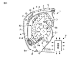
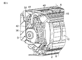
図1は空気調和機の室内機における概略の縦断面図、図2は室内機本体1の前面パネル2を外して内部を見せた正面斜視図である。(なお、説明中に符号を付していない部品は図示していない。以下同じ)
室内機本体1は、前面パネル2と後板筐体3とから構成されていて、正面視で横長状をなす。前面パネル2の前面側一部に前部吸込み口4が開口され、開閉駆動機構に支持された可動パネルPが嵌め込まれている。運転停止時および後述するエアフィルタ清掃機構Aとファン清掃機構Bの作動時には、可動パネルPは前面パネル2と同一面となり前部吸込み口4を閉成する。また、空調運転時には可動パネルPは手前側に突出変位し、本体1との間に隙間を形成して前部吸込み口4を開放するよう制御される。
Hereinafter, embodiments of the present invention will be described in detail with reference to the drawings.
FIG. 1 is a schematic longitudinal sectional view of an indoor unit of an air conditioner, and FIG. 2 is a front perspective view of the interior of the
The
前面パネル2および後板筐体3の上部に亘って上部吸込み口5が設けられる。上部吸込み口5には枠状の桟6が嵌め込まれていて、この桟6によって複数の空間部に仕切られている。上記可動パネルP下部には吹出し口7が開口されていて、この吹出し口7には吹出しルーバー8が設けられる。上記吹出しルーバー8は、運転停止時およびエアフィルタ清掃機構Aとファン清掃機構Bの作動時には上記吹出し口7を開閉し、かつ空調運転条件に応じて熱交換空気の吹出し方向を設定できる。
An
室内機本体1内には、前側熱交換器部10Aと後側熱交換器部10Bとで略逆V字状に形成される熱交換器10が配置される。前側熱交換器部10Aは、前面パネル2と間隙を存してほぼ平行な湾曲状に形成されて前部吸込み口4および上部吸込み口5の一部と対向し、後側熱交換器部10Bは直状に形成されて上部吸込み口5と傾斜して対向する。
In the indoor unit
上記前側熱交換器部10Aの下端部は前ドレンパン9a上に載り、後側熱交換器部10Bの下端部は後ドレンパン9b上に載って、それぞれの熱交換器部10A,10Bから滴下するドレン水を受け、図示しない排水ホースを介して外部に排水できるようになっている。
The lower end portion of the front
一方、前部吸込み口4と前側熱交換器部10Aとの間には、前部エアフィルタ11Aが取付けられる。上部吸込み口5と前側熱交換器部10A一部および上側熱交換器部10Bとの間には、上部エアフィルタ11Bが取付けられる。これら前部エアフィルタ11Aと上部エアフィルタ11Bはともに、従来の室内機のようにユーザーが容易に着脱できる構成としなくてもよい。
On the other hand, a
すなわち、前部エアフィルタ11Aと上部エアフィルタ11Bは、その表面側に備えられる上記エアフィルタ清掃機構Aにより、捕捉し付着している塵埃を自動的に除去されるようになっている。したがって、前部エアフィルタ11Aと上部エアフィルタ11Bは専門作業者がメンテナンス等、必要に応じて取外し可能な構成であればよい。
That is, the
上記エアフィルタ清掃機構Aは、長手方向の両側端部が前部エアフィルタ11Aと上部エアフィルタ11Bの幅方向両側部に沿って設けられる左右一対のメーンガイド12に支持され、中間部が前部エアフィルタ11Aと上部エアフィルタ11Bの中間部に設けられる左右一対のサブガイド13に支持される。上記メーンガイド12およびサブガイド13ともに、前部エアフィルタ11Aの下端部(吹出し口7の上端部でもある)から上部エアフィルタ11Bの後端部に亘って設けられる。
The air filter cleaning mechanism A is supported by a pair of left and right
上記メーンガイド12表面にはいわゆるラックaが設けられるのに対して、上記エアフィルタ清掃機構Aは上記ラックaに噛合するピニオンギヤを備えている。そしてエアフィルタ清掃機構Aの一側部には、上記ピニオンギヤを駆動する駆動機構を備えているので、ピニオンギヤを回転駆動することでエアフィルタ清掃機構Aはメーンガイド12とサブガイド13に沿って自走できる。
A so-called rack a is provided on the surface of the
上記エアフィルタ清掃機構Aは、左右のメーンガイドに亘って架設される横長状のダストボックス15と、このダストボックス15内の一側部に収容され、ダストボックス15の全長に亘る軸方向長さのロールブラシ16と、ダストボックス15内の他側部に形成される塵埃受け通路17および、上記ロールブラシ16を回転駆動するブラシ駆動機構とから構成される。
The air filter cleaning mechanism A includes a horizontally
上記ロールブラシ16は、その毛先が前部エアフィルタ11Aと上部エアフィルタ11Bに接触するよう支持される。したがって、ロールブラシ16が回転駆動されることで、前部エアフィルタ11Aと上部エアフィルタ11Bに付着する塵埃を除去しダストボックス15内に取入れることができる。上記塵埃受け通路17は、ロールブラシ16が除去した塵埃を受け入れる位置に形成されている。
The
再び図1に示すように、上記傘状に形成される熱交換器10の前後側熱交換器部10A,10B相互間に室内送風機20が配置される。上記室内送風機20は、ファンモータと、このファンモータの回転軸に一方の支軸が機械的に連結されるファン21とから構成される。上記ファン21は、横流ファン(クロスフローファン)であって、後述する加工が施されている。
As shown in FIG. 1 again, the
なお、図2のみに示す(図1では省略)ように、上記熱交換器10の前側熱交換器部10Aにおける前面部で、前部エアフィルタ11Aとの間には空気清浄ユニットCが取付けられている。この空気清浄ユニットCは前部エアフィルタ11Aが捕捉できない細かい塵埃を集塵付着するとともに、脱臭作用も行う。
As shown only in FIG. 2 (omitted in FIG. 1), an air cleaning unit C is attached between the
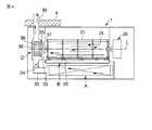
図3は、上記横流ファン21の概略の構成図である。
上記横流ファン21は、軸方向の両側部に設けられる円板状の端板22と、これら両側端板22の間に所定間隔を存して並置される複数枚の円板状の中間仕切り板23と、これら両側端板22と中間仕切り板23の周端部に沿って設けられる溝部を貫通し、たとえば接着等の手段をもって取付け固定される複数枚の羽根24からなる。
FIG. 3 is a schematic configuration diagram of the
The
図中右側の端板22の軸芯部には孔部22aが設けられていて、ここに上記ファンモータの回転軸が挿入され、かつ固定される。図中左側の端板22の軸芯部には支軸22bが外方へ突設されていて、この支軸22bは横流ファン21側部に設けられる軸受部に支持される。
A
さらに、図中右側の端板22には、上記孔部22aと周端部との間に複数の円弧状長孔bが設けられ、左側の端板22には支軸22bと周端部との間に複数の孔部cが設けられる。上記中間仕切り板23には、上記羽根24の取付け部位を除く軸芯部に円形の開口部dが設けられる。
Further, the
上記横流ファン21は回転駆動されることによって周方向から空気を吸込み、周方向へ吹出すことができる。その一方で、一方の端板22に設けられる円弧状長孔bと、中間仕切り板23に設けられる開口部dおよび他方の端板22に設けられる孔部cとが互いに連通状態となっている。すなわち、横流ファン21を構成する羽根24の内側に、上記孔部b等からなる塵埃回収用開口部25が形成されている。
The
再び図1に示すように、前後ドレンパン9a,9bの一部側壁外面は室内送風機20に近接した位置に設けられ、これらで室内送風機20の横流ファン21に対するノーズを構成している。ノーズを構成する前後ドレンパン9a,9bの側壁部分と吹出し口7の各辺部との間は、隔壁部材26によって連結される。隔壁部材26で囲まれる空間が、ノーズと吹出し口7とを連通する吹出し送風路27となる。
As shown in FIG. 1 again, the outer surfaces of the side walls of the front and rear drain pans 9a and 9b are provided at positions close to the
上記室内送風機20の横流ファン21を回転駆動することにより、前部吸込み口4および上部吸込み口5と、上記吹出し口7とを連通する送風路28が形成され、その一部が上記吹出し送風路27となる。上記前部エアフィルタ11Aおよび上部エアフィルタ11Bと、熱交換器10と、室内送風機20は、上記送風路28の上流側から下流側に沿って、順に配置されることになる。
By rotating and driving the
上記前ドレンパン9aのノーズ構成部の近傍に、上記室内送風機20の横流ファン21を掃除する上記ファン清掃機構Bが設けられる。このファン清掃機構Bは、横流ファン21の軸方向全長に亘って対向配置されるブラシ等の清掃具30と、この清掃具30を進退移動させる進退駆動機構とから構成される。清掃具30を進出移動した状態で、ブラシの毛先が横流ファン21に接触し、後退移動することでブラシの毛先が横流ファン21から離間するよう設定されている。
The fan cleaning mechanism B for cleaning the
上記熱交換器10の一側部に電気部品箱29が並置される。この電気部品箱29内には、リモコンから送られる信号や各種のセンサ類から送られてくる信号にもとづいて、室内送風機20他の電動部品を制御する半導体部品および電気部品の集合体である制御部Sが収容されている。一部の電気部品は発熱量が著しく大であるので、冷却用空気を取入れてその電気部品を冷却し、温度上昇した空気を取出す冷却用開口部を備えていて、密閉化されていない。
An
また、上記電気部品箱29とは反対側の熱交換器10側部には、後述する吸排気機構Dが設けられている。この吸排気機構Dは上記室内送風機20を構成する横流ファン21の側部に隣設され、この横流ファン21の軸心の延長上に軸心を有している。
つぎに、上記吸排気機構Dについて詳述する。
図4は吸排気機構Dに対するエアフィルタ清掃機構Aとファン清掃機構Bの作用説明図、図5は吸排気機構Dとエアフィルタ清掃機構A一部の斜視図、図6は吸排気機構Dの一部を拡大した斜視図、図7は吸排気機構Dを分解した斜視図、図8は吸排気機構Dの作用を説明する図である。
An intake / exhaust mechanism D, which will be described later, is provided on the side of the
Next, the intake / exhaust mechanism D will be described in detail.
4 is a diagram for explaining the operation of the air filter cleaning mechanism A and the fan cleaning mechanism B with respect to the intake / exhaust mechanism D, FIG. 5 is a perspective view of a part of the intake / exhaust mechanism D and the air filter cleaning mechanism A, and FIG. FIG. 7 is an exploded perspective view of a part of the intake / exhaust mechanism D, and FIG.
上記吸排気機構Dは、上記エアフィルタ清掃機構Aおよび上記ファン清掃機構Bが除去した塵埃を室外へ排出する機能を備えている。なお説明すると、特に図4に示すように、上記エアフィルタ清掃機構Aと吸排気機構Dの間には、除去した塵埃を案内するエアフィルタ用案内路32が介設され、上記ファン清掃機構Bと吸排気機構Dとの間には、除去した塵埃を案内するファン用案内路33が形成される。
The intake / exhaust mechanism D has a function of discharging dust removed by the air filter cleaning mechanism A and the fan cleaning mechanism B to the outside. Specifically, as shown in FIG. 4, an air
エアフィルタ用案内路32およびファン用案内路33は、互いに逆に開閉動作する開閉機構34,35を備えている。すなわち、エアフィルタ用案内路32を開閉機構34が開放したときはファン用案内路33を開閉機構35が閉成し、ファン用案内路33を開閉機構35が開放したときはエアフィルタ用案内路32を開閉機構34が閉成するよう作用する。
The air
上記エアフィルタ用案内路32は、上記吸排気機構Dを構成するファンケーシング36の周面一部に接続される。上記ファン用案内路33は、上記吸排気機構Dに形成される塵埃導入口37と対向していて、この塵埃導入口37は上記横流ファン21の軸受部と対向する位置にある。
The air
したがって、エアフィルタ用案内路32とファン用案内路33は吸排気機構Dで合流する。そのため、エアフィルタ清掃機構Aとファン清掃機構Bに対して1つの吸排気機構Dで対応でき、部品の共通化による室内機本体1のコンパクト化とメンテナンスの簡素化を得られる。
Therefore, the air
吸排気機構Dはファンケーシング36内に多翼型ファンからなる換気ファン38を備えている。換気ファン38と横流ファン21の軸芯は同一の軸L上にあり、これらの間に上記塵埃導入口37が形成されることとなる。
しかも、ファン清掃機構Bと吸排気機構Dは互いに連動するよう制御される。たとえば、ファン清掃機構Bの作動開始にタイミングを合わせて吸排気機構Dを作動開始してもよく、ファン清掃機構Bが作動を開始して所定時間が経過したあとで吸排気機構Dを作動させてもよく、あるいは吸排気機構Dの作動を開始して所定時間が経過したあとファン清掃機構Bを作動させてもよい。
The intake / exhaust mechanism D includes a
Moreover, the fan cleaning mechanism B and the intake / exhaust mechanism D are controlled so as to interlock with each other. For example, the intake / exhaust mechanism D may be started in synchronism with the start of operation of the fan cleaning mechanism B, and the intake / exhaust mechanism D is operated after a predetermined time has elapsed since the fan cleaning mechanism B started operating. Alternatively, the fan cleaning mechanism B may be operated after a predetermined time has elapsed after the operation of the intake / exhaust mechanism D is started.
さらに、ファンケーシング36には排気ダクト39が接続されていて、この排気ダクト39は家屋の壁Kを貫通して開口端部が屋外へ延出される。
図5に示すように、上記エアフィルタ清掃機構Aを構成するダストボックス15の一方の端部のみ開口され、排出ボックス40でカバーされる。この排出ボックス40と上記吸排気機構Dの上記ファンケーシング36は接続ホース41で連通されていて、この接続ホース41が上記エアフィルタ用案内路32の一部を形成することになる。
Further, an
As shown in FIG. 5, only one end of the
上記接続ホース41は全体的に緩やかな曲線をなすよう曲成されていて、内部を導通する塵埃が途中で詰まらないように配慮されている。そして、エアフィルタ清掃機構Aの作動時においてダストボックス15の移動および変位位置の影響を受けることのない充分な長さを有する。
The
上記吸排気機構Dを構成するファンケーシング36はスクロール状に形成され、周面一部に上記接続ホース41が接続される口体を備えた塵埃案内用ケース42が設けられる。したがって、塵埃案内用ケース42と上記接続ホース41でエアフィルタ用案内路32が形成される。
The
図6に示すように、この塵埃案内用ケース42の一部はダンパケース43として突設され、このダンパケース43内にエアフィルタ用案内路32の上記開閉機構34である風力ダンパが設けられる。
上記風力ダンパ34は、側面視で略への字状に折曲される板片からなっていて、上記ダンパケース43は風力ダンパ34の形状に合致するよう突出形成される。風力ダンパ34の一端は支軸を介して塵埃案内用ケース42に回動自在に支持され、風力ダンパ34の他端は重力で垂れ下がって塵埃案内用ケース42内を遮断する。
As shown in FIG. 6, a part of the
The
接続ホース41に所定圧以上の風圧(負圧)が加わると、風力ダンパ34の自由端は風圧で上方に押され、エアフィルタ用案内路32を開放する。この状態から所定圧以上の風圧が無くなれば、もしくは正圧が加われば、風力ダンパ34はエアフィルタ用案内路32を遮断するようになっている。
When a wind pressure (negative pressure) equal to or higher than a predetermined pressure is applied to the
図7および図8に示すように、上記吸排気機構Dは、一側部にユニットベース45が設けられ、他側部に上記ファンケーシング36を有する送風機構50が設けられるとともに、ユニットベース45と送風機構50との間には、上記ファン用案内路33の開閉機構35である換気ダンパおよびダンパ駆動機構55が介設される。(なお、ここでは上記塵埃案内用ケース42については省略している)
上記ユニットベース45の上部は、熱交換器10を構成する前側熱交換器部10Aと後側熱交換器部10Bの組合せ形状と合致し、かつ熱交換器10の側端部が載る。ユニットベース45の略中央部には周縁に沿ってリブfが突設される取付け用開口部46が設けられる。この取付け用開口部46の略半周に沿い、互いに所定間隔を存して複数の全閉用片部47が設けられ、一部の全閉用片部47相互間には2次用換気口48が開口される。
As shown in FIGS. 7 and 8, the intake / exhaust mechanism D is provided with a
The upper part of the
上記取付け用開口部46に軸受具49が嵌着固定され、上記室内送風機20を構成する横流ファン21の支軸22bを軸支している。内面側に突設される2本のステーgにダンパ駆動機構55を構成する小ギヤ56が回転自在に嵌着される。他のステーhの端面ねじ孔に、送風機構50を取付け固定する取付けねじ51が螺挿される。
A bearing
ユニットベース45には,ダンパ駆動機構55を構成する駆動用モータ57が取付け固定され、さらに駆動用モータ57の回転軸に連結する駆動ギヤ58が回転自在に支持される受部59が設けられる。
The
上記換気ダンパ35の中心部に設けられる孔部60が、上記取付け用開口部46周面に沿って形成されるリブfに回転自在に嵌め込まれる。換気ダンパ35は、孔部60から径方向に沿って断面略皿状に形成され、円形状の外周縁に沿ってギヤ部Gが設けられる。このギヤ部Gには、ダンパ駆動機構55を構成する2個の小ギヤ56と駆動ギヤ58が噛合する。
A hole 60 provided at the center of the
上記換気ダンパ35における孔部60と外周のギヤ部Gとの間で、周方向の一部には複数の案内用換気口62が設けられる。これら案内用換気口62は、ユニットベース45の上記2次用換気口48と全く同一の開口寸法形状をなし、案内用換気口62相互間隔は、上記全閉用片部47相互間隔と同一に設定されている。
Between the hole portion 60 and the outer peripheral gear portion G in the
上記換気ダンパ35はリブfに嵌め込まれた状態で、ユニットベース45内面と間隙を存し、かつ換気ダンパ35の一側面は全閉用片部47端縁に常に摺接状態にある。したがって、換気ダンパ35の案内用換気口62が2次用換気口48と対向している状態を除いて、各2次用換気口48は換気ダンパ35によって閉塞される。
When the
上記送風機構50は、換気ダンパ35側の側面に対して開口する吸気口63を備え、周端部に排気口体64が突設される上記ファンケーシング36と、このファンケーシング36の吸気口63対向面に取付けられるファンモータ65と、このファンモータ65の回転軸に取付けられる上記換気ファン38とから構成される。
The
上記換気ファン38は、回転にともなって軸心方向から空気を吸込んで周方向へ送風する、いわゆる遠心ファンタイプ(多翼型)である。実際には、ファンケーシング36の吸気口63から空気を吸込んで排気口体64へ送風する作用をなす。上記排気口体64には先に図4で示した排気ダクト39が接続されていて、この排気ダクト39は壁Kを貫通して屋外へ延出されることは上述のとおりである。
The
このようにして構成される空気調和機の室内機であって、リモコンの運転スイッチをオンに切換えると、可動パネルPが前部吸込み口4を開放し、冷房運転と暖房運転の指定に応じて吹出し口7に備えられる吹出しルーバー8が回動して風向姿勢が設定される。同時に、室内送風機20が送風作用をなす一方で、室外機の圧縮機が駆動され冷凍サイクル運転が開始される。
The indoor unit of the air conditioner configured as described above, when the operation switch of the remote control is turned on, the movable panel P opens the front suction port 4 and according to the designation of the cooling operation and the heating operation. The
室内空気は、前部吸込み口4と上部吸込み口5とから室内機本体1内に形成される送風路28に沿って導かれる。すなわち、室内空気は前部エアフィルタ11Aおよび上部エアフィルタ11Bを通過し、室内空気中に含まれる塵埃が捕捉される。さらに、空気清浄ユニットCを流通して清浄化した室内空気は熱交換器10に導かれて熱交換作用が行われる。この熱交換空気は吹出し送風路27から吹出し口7に導かれ、吹出しルーバー8に案内されて室内へ吹出され、効率のよい空調運転を継続できる。
The room air is guided from the front suction port 4 and the
上記空調運転を長期間継続すると、必然的に前、上部エアフィルタ11A,11Bに室内空気から捕捉した塵埃が堆積するとともに、各エアフィルタ11A,11Bと熱交換器10を通過した塵埃が室内送風機20を構成する横流ファン21に静電気の影響で付着する。
If the air-conditioning operation is continued for a long period of time, the dust trapped from the room air inevitably accumulates in the
そこで制御部Sは、空調運転の終了の都度、もしくは所定の空調運転累積時間の経過後に、上記エアフィルタ清掃機構Aとファン清掃機構Bに作動開始信号を送る。もしくは、ユーザーが任意でリモコンの掃除スイッチを押すことで、制御部Sから各清掃機構A,Bへ作動開始信号を送れるように設定してもよい。 Therefore, the control unit S sends an operation start signal to the air filter cleaning mechanism A and the fan cleaning mechanism B every time the air conditioning operation ends or after a predetermined cumulative air conditioning operation time has elapsed. Or you may set so that an operation start signal can be sent to each cleaning mechanism A and B from the control part S by a user pushing the cleaning switch of a remote control arbitrarily.
上記制御部Sは、可動パネルPの駆動機構へ信号を送って前部吸込み口4を閉成するとともに、吹出しルーバー8の駆動機構へ信号を送って吹出し口7を閉成する。すなわち、予め室内機本体1を略密閉構造化して収集した塵埃が漏れるのを可能な限り防御する。これらの閉成完了後のタイミングをとって、はじめにエアフィルタ清掃機構Aへ作動開始信号が送られる。
The control unit S sends a signal to the drive mechanism of the movable panel P to close the front suction port 4 and sends a signal to the drive mechanism of the
運転停止時は勿論のこと空調運転時においても、エアフィルタ清掃機構Aを構成するダストボックス15は図1に示すように前部吸込み口4上端と上部吸込み口5前端と間の前面パネル2部位と対向する位置にあるので、特に空調運転中において前部吸込み口4と上部吸込み口5から本体1内に吸込まれる室内空気の流通障害とならない。
As shown in FIG. 1, the
エアフィルタ清掃機構Aに作動開始信号が送られると、ピニオンギヤが駆動されてダストボックス15はメーンガイド12とサブガイド13に案内され、前部エアフィルタ11Aの前面側に沿って移動する。同時に、ブラシ駆動機構がダストボックス15内のロールブラシ16を回転駆動して、その毛先が前部エアフィルタ11Aに接触する。前部エアフィルタ11Aに付着している塵埃はロールブラシ16によって掻き落され、かつダストボックス15内の塵埃受け通路17に受け入れられる。
When an operation start signal is sent to the air filter cleaning mechanism A, the pinion gear is driven, the
上記ダストボックス15が前部エアフィルタ11Aの上端から下端に亘って移動したら、今度は下端から上端へ向って移動し、前部エアフィルタ11Aに残っている塵埃を除去する。その後、ダストボックス15は上部エアフィルタ11Bの前端から後端に亘って移動して付着している塵埃を除去し、再び上部エアフィルタ11Bの前端位置に戻って塵埃を除去してから、清掃作用を停止する。
When the
前部エアフィルタ11Aと上部エアフィルタ11Bともに2度ずつ塵埃の除去作業がなされ、清掃効果が完璧となる。ダストボックス15の塵埃受け通路17には各エアフィルタ11A,11Bから除去した塵埃が収集されているので、制御部Sはエアフィルタ清掃機構Aへ作業終了信号を送ったあと、吸排気機構Dへ作動信号を送り、収集された塵埃を屋外へ排出する。
Both the
上記吸排気機構Dは、「2次側空気換気モード」と、「1次側空気換気モード」および「ダンパ全閉モード」の3種類のモードに切換えられるようになっている。なお、2次側、1次側の呼称は、ここでは上記熱交換器10を基準としていて、2次側空気は熱交換器10を流通したあとの空気を言い、1次側空気は熱交換器10に流通する以前の空気を言う。
The intake / exhaust mechanism D can be switched to three types of modes: “secondary air ventilation mode”, “primary air ventilation mode”, and “damper fully closed mode”. Here, the designation of the secondary side and the primary side is based on the
上記制御部Sは、吸排気機構Dを作動する際に、「ダンパ全閉モード」を選択する。換気ダンパ35が回動され、案内用換気口62がユニットベース45の全閉用片部47とリブfによって囲まれて完全閉成状態になる。また、ユニットベース45の2次用換気口48が換気ダンパ35面によって完全閉成され、ファンケーシング36の吸気口63が閉塞される。すなわち、開閉機構である換気ダンパ35は塵埃導入口37を閉成し、したがってファン用案内路33が閉成される。
When the intake / exhaust mechanism D is operated, the control unit S selects the “damper fully closed mode”. The
ついで、送風機構50が作用して換気ファン38が回転駆動されると、ファンケーシング36内が負圧状態となる。この影響でダンパケース43内も負圧状態となり、開閉機構である風力ダンパ34はエアフィルタ用案内路32を開放する。
Next, when the
エアフィルタ用案内路32を介してダストボックス15内の塵埃受け通路17にも負圧がかかることになり、ここに収集されていた塵埃がエアフィルタ用案内路32からファンケーシング36内に導かれ、さらに排気ダクト39を介して屋外へ排出される。換気ダンパ35がファン用案内路33を閉成すると、風力ダンパ34はエアフィルタ用案内路32を開放する。
Negative pressure is also applied to the dust receiving passage 17 in the
エアフィルタ清掃機構Aが収集した塵埃を屋外へ排出したあと、制御部Sはファン清掃機構Bへ作業開始信号を送るとともに、吸排気機構Dへは「2次側空気換気モード」への切換え信号を送る。ファン清掃機構Bを構成する進退駆動機構は、清掃具30を進出移動させてブラシの毛先を横流ファン31に接触させる。
After the dust collected by the air filter cleaning mechanism A is discharged to the outside, the control unit S sends a work start signal to the fan cleaning mechanism B, and the intake / exhaust mechanism D is switched to “secondary air ventilation mode”. Send. The forward / backward drive mechanism that constitutes the fan cleaning mechanism B moves the
そのうえで、制御部Sは横流ファン31を低速運転させる。すなわち、空調運転中は横流ファン31を正回転駆動し、ファン清掃機構Bの作動中は横流ファン31を逆回転駆動する、もしくは正回転駆動と逆回転駆動を繰り返すよう制御する。
図8に示すように、横流ファン31の回転にともなってブラシ清掃具30の毛先が摺接し、横流ファン31に付着していた塵埃が除去される。同時に、吸排気機構Dにおけるダンパ駆動機構55が作動して換気ダンパ35を回動させ、換気ダンパ35の案内用換気口62とユニットベース45の2次用換気口48が対向する。
In addition, the control unit S operates the cross flow fan 31 at a low speed. That is, the cross flow fan 31 is driven to rotate forward during the air conditioning operation, and the cross flow fan 31 is driven to rotate reversely during the operation of the fan cleaning mechanism B, or the forward rotation drive and the reverse rotation drive are repeated.
As shown in FIG. 8, the hair tip of the
すなわち、吸排気機構Dの塵埃導入口37が開放され、かつ塵埃導入口37と横流ファン31の塵埃回収用開口部25とが、ユニットベース45と横流ファン31の端板22との間隙であるファン用案内路33を介して対向することになる。
上記横流ファン31の低速回転により常時開放している上部吸込み口5から室内空気が室内機本体1内に吸込まれ、熱交換器10を流通する。そして、熱交換器10から流出した2次側空気は換気ファン38の作動により、2次用換気口48と案内用換気口62および吸気口63を介して吸排気機構D内に吸込まれる。
That is, the
The indoor air is sucked into the
同時に、塵埃導入口37からファン用案内路33を介して横流ファン31の塵埃回収用開口部25に負圧がかかる。横流ファン31から掻き落された塵埃は塵埃回収用開口部25からファン用案内路33に導かれ、塵埃導入口37において2次側空気と合流して吸排気機構D内に導入される。そして、2次側空気とともに塵埃は排気ダクト39を介して屋外へ排出される。
At the same time, negative pressure is applied from the
このようにして、換気ダンパ35がファン用案内路33を開放すると、風力ダンパ34はエアフィルタ用案内路32を閉成する。上記ファン用案内路33は、横流ファン31側端端部とユニットベース45との間隙から形成され、エアフィルタ用案内路32のような接続ホース41は存在しないが、距離が短く、かつ塵埃回収用開口部25に対する負圧が大であるので、塵埃の屋外排出は無理なく行われる。
In this way, when the
また、吸排気機構Dは「1次側空気換気モード」も選択できる。このときは、換気ダンパ35の案内用換気口62の位置をユニットベース45の2次用換気口48の位置からずらし、ダンパ35面をユニットベース45の全閉用片部47端縁に接触させ、2次用換気口48を換気ダンパ35で閉成する。したがって、送風機構50周面とユニットベース45内面とは間隙が形成され、案内用換気口62は上記間隙と連通して1次側空気が導かれる。
The intake / exhaust mechanism D can also select a “primary air ventilation mode”. At this time, the position of the guide ventilation port 62 of the
ただし、上記塵埃導入口37を構成する2次用換気口48が閉成されるので、換気ファン38を駆動しても横流ファン31の塵埃回収用開口部25に対して負圧をかけ難く、吸排気機構D内に塵埃を吸込み難くなる。したがって、吸排気機構Dが「1次側空気換気モード」を選択した際には、ファン清掃機構Bは連動しない。
However, since the
なお、「2次側空気換気モード」と「1次側空気換気モード」において、送風機構50を構成するファンケーシング36から上記ダンパケース43に対して送風圧がかかるので、ダンパケース43に設けられる風力ダンパ34が接続ホース41側への気流の流れを防止する。したがって、接続ホース41からダストボックス15への気流の逆流がない。
In the “secondary air ventilation mode” and the “primary air ventilation mode”, the air pressure is applied to the
このように本発明においては、前、上部エアフィルタ11A,11Bと室内送風機20の横流ファン21にそれぞれ接触して、これらに付着する塵埃を自動で除去するので、洗浄液を用いる必要がない。各エアフィルタ11A,11Bとファン21に対する掃除手間が軽減化して、室内機本体1内部の清潔度の向上化を図れる。
As described above, in the present invention, the
本発明は上述した実施の形態そのままに限定されるものではなく、実施段階ではその要旨を逸脱しない範囲で構成要素を変形して具体化できる。そして、上述した実施の形態に開示されている複数の構成要素の適宜な組合せにより種々の発明を形成できる。 The present invention is not limited to the above-described embodiments as they are, and can be embodied by modifying the components without departing from the scope of the invention in the implementation stage. Various inventions can be formed by appropriately combining a plurality of constituent elements disclosed in the above-described embodiments.
4,5…(前部、上部)吸込み口、7…吹出し口、1…室内機本体、28…送風路、11A…前部エアフィルタ、11B…上部エアフィルタ、10…熱交換器、20…送風機、A…エアフィルタ清掃機構、B…ファン清掃機構、D…吸排気機構、37…塵埃導入口、30…清掃具(回転ブラシ)、22…端板、23…中間仕切り板、24…羽根、21…横流ファン、25…塵埃回収用開口部。 4, 5 (front, upper) suction port, 7 ... outlet, 1 ... indoor unit main body, 28 ... air passage, 11A ... front air filter, 11B ... upper air filter, 10 ... heat exchanger, 20 ... Blower, A ... Air filter cleaning mechanism, B ... Fan cleaning mechanism, D ... Intake / exhaust mechanism, 37 ... Dust inlet, 30 ... Cleaning tool (rotary brush), 22 ... End plate, 23 ... Intermediate partition plate, 24 ... Blade , 21 ... Cross-flow fan, 25 ... Dust collection opening.
Claims (2)
この室内機本体内に形成され、上記吸込み口と吹出し口とを連通する送風路と、
この送風路に沿って配置されるエアフィルタ、熱交換器および横流ファンと、
上記横流ファンに接触し、横流ファンに付着する塵埃を、横流ファンの回転にともなって除去するファン清掃機構と、
上記横流ファン側部に隣設され、横流ファンの側端面に対向してファン清掃機構部と連通する塵埃導入口が形成され、ファン清掃機構が除去した塵埃を空気とともに上記塵埃導入口から吸入して室外へ排出する吸排気機構と
を具備することを特徴とする空気調和機の室内機。 An indoor unit body equipped with a room air inlet and a heat exchange air outlet;
A blower passage formed in the indoor unit main body and communicating the suction port and the blowout port,
An air filter, a heat exchanger and a cross flow fan arranged along the air passage;
A fan cleaning mechanism that contacts the crossflow fan and removes dust adhering to the crossflow fan as the crossflow fan rotates;
A dust inlet that is adjacent to the side of the cross-flow fan and communicates with the fan cleaning mechanism is formed facing the side surface of the cross-flow fan, and dust removed by the fan cleaning mechanism is sucked together with air from the dust inlet. An air conditioner indoor unit comprising an intake / exhaust mechanism that exhausts the air to the outside.
上記横流ファンの両側端板および中間仕切り板の軸芯部に、上記ファン清掃機構が掻き落した塵埃を案内する塵埃回収用開口部を備えたことを特徴とする請求項1記載の空気調和機の室内機。 The cross-flow fan includes both side end plates and an intermediate partition plate made of discs provided at predetermined intervals in the axial direction, and a plurality of blades installed between the both side end plates and the intermediate partition plate. With
2. An air conditioner according to claim 1, wherein a dust collection opening for guiding the dust scraped off by the fan cleaning mechanism is provided at both side end plates of the cross flow fan and the shaft core of the intermediate partition plate. Indoor unit.
Priority Applications (1)
| Application Number | Priority Date | Filing Date | Title |
|---|---|---|---|
| JP2006268632A JP4909699B2 (en) | 2006-09-29 | 2006-09-29 | Air conditioner indoor unit |
Applications Claiming Priority (1)
| Application Number | Priority Date | Filing Date | Title |
|---|---|---|---|
| JP2006268632A JP4909699B2 (en) | 2006-09-29 | 2006-09-29 | Air conditioner indoor unit |
Related Parent Applications (1)
| Application Number | Title | Priority Date | Filing Date |
|---|---|---|---|
| JP2006165026 Division | 2006-06-14 | 2006-06-14 |
Publications (2)
| Publication Number | Publication Date |
|---|---|
| JP2007333371A JP2007333371A (en) | 2007-12-27 |
| JP4909699B2 true JP4909699B2 (en) | 2012-04-04 |
Family
ID=38933002
Family Applications (1)
| Application Number | Title | Priority Date | Filing Date |
|---|---|---|---|
| JP2006268632A Expired - Fee Related JP4909699B2 (en) | 2006-09-29 | 2006-09-29 | Air conditioner indoor unit |
Country Status (1)
| Country | Link |
|---|---|
| JP (1) | JP4909699B2 (en) |
Families Citing this family (6)
| Publication number | Priority date | Publication date | Assignee | Title |
|---|---|---|---|---|
| JP2017203588A (en) * | 2016-05-11 | 2017-11-16 | 日立ジョンソンコントロールズ空調株式会社 | Air conditioner |
| WO2019220492A1 (en) * | 2018-05-14 | 2019-11-21 | 日立ジョンソンコントロールズ空調株式会社 | Air conditioner |
| EP3795911B1 (en) * | 2018-05-14 | 2023-03-15 | Hitachi-Johnson Controls Air Conditioning, Inc. | Air conditioner |
| CN111102650A (en) * | 2019-12-18 | 2020-05-05 | 珠海格力电器股份有限公司 | Self-cleaning air conditioner and control method |
| CN112484151B (en) * | 2020-11-19 | 2021-11-05 | 珠海格力电器股份有限公司 | Air conditioner |
| CN115597111B (en) * | 2022-09-05 | 2024-08-20 | 珠海格力电器股份有限公司 | Cleaning device for air conditioner, cleaning method for air conditioner and air conditioner |
Family Cites Families (2)
| Publication number | Priority date | Publication date | Assignee | Title |
|---|---|---|---|---|
| JP2002267249A (en) * | 2001-03-09 | 2002-09-18 | Sharp Corp | Fluid-delivering device |
| JP4860131B2 (en) * | 2004-10-01 | 2012-01-25 | パナソニック株式会社 | Method for controlling dust suction device of air conditioner |
-
2006
- 2006-09-29 JP JP2006268632A patent/JP4909699B2/en not_active Expired - Fee Related
Also Published As
| Publication number | Publication date |
|---|---|
| JP2007333371A (en) | 2007-12-27 |
Similar Documents
| Publication | Publication Date | Title |
|---|---|---|
| JP2008002767A (en) | Indoor unit of air conditioner | |
| JP2008134004A (en) | Indoor unit of air conditioner | |
| KR101049433B1 (en) | Air conditioner | |
| JP4815452B2 (en) | Air conditioner | |
| JP4909699B2 (en) | Air conditioner indoor unit | |
| KR100917725B1 (en) | Indoor unit of air-conditioner | |
| JP4648208B2 (en) | Air conditioner indoor unit | |
| JPWO2007145254A1 (en) | Air conditioner indoor unit | |
| JP2006183996A (en) | Air conditioner | |
| JP5755088B2 (en) | Air conditioner indoor unit | |
| JP4878521B2 (en) | Air conditioner indoor unit | |
| JP2008145074A (en) | Indoor unit of air conditioner | |
| JP3992722B2 (en) | Air conditioner | |
| JP2008045822A (en) | Indoor unit of air conditioner | |
| JP2009156557A (en) | Indoor unit of air conditioner | |
| WO2008062876A1 (en) | Air conditioning apparatus indoor unit | |
| JP2008039324A (en) | Indoor unit of air conditioner | |
| JP2008045824A (en) | Indoor unit of air conditioner | |
| JP2011202931A (en) | Indoor unit of air conditioner | |
| JP4709039B2 (en) | Air conditioner indoor unit | |
| KR20050118784A (en) | A ventilation system of window type | |
| JP2008045823A (en) | Indoor unit of air conditioner | |
| JP2008175512A (en) | Indoor unit for air conditioner | |
| JP2008121965A (en) | Indoor unit of air conditioner | |
| JP2008057832A (en) | Indoor unit of air conditioner |
Legal Events
| Date | Code | Title | Description |
|---|---|---|---|
| A711 | Notification of change in applicant |
Free format text: JAPANESE INTERMEDIATE CODE: A712 Effective date: 20080528 |
|
| A621 | Written request for application examination |
Free format text: JAPANESE INTERMEDIATE CODE: A621 Effective date: 20090325 |
|
| A977 | Report on retrieval |
Free format text: JAPANESE INTERMEDIATE CODE: A971007 Effective date: 20110408 |
|
| A131 | Notification of reasons for refusal |
Free format text: JAPANESE INTERMEDIATE CODE: A131 Effective date: 20110517 |
|
| A521 | Written amendment |
Free format text: JAPANESE INTERMEDIATE CODE: A523 Effective date: 20110701 |
|
| TRDD | Decision of grant or rejection written | ||
| A01 | Written decision to grant a patent or to grant a registration (utility model) |
Free format text: JAPANESE INTERMEDIATE CODE: A01 Effective date: 20120110 |
|
| A01 | Written decision to grant a patent or to grant a registration (utility model) |
Free format text: JAPANESE INTERMEDIATE CODE: A01 |
|
| A61 | First payment of annual fees (during grant procedure) |
Free format text: JAPANESE INTERMEDIATE CODE: A61 Effective date: 20120116 |
|
| FPAY | Renewal fee payment (event date is renewal date of database) |
Free format text: PAYMENT UNTIL: 20150120 Year of fee payment: 3 |
|
| R150 | Certificate of patent or registration of utility model |
Free format text: JAPANESE INTERMEDIATE CODE: R150 |
|
| LAPS | Cancellation because of no payment of annual fees |