JP4590969B2 - Wireless communication system, wireless communication apparatus, wireless communication method, and computer program - Google Patents
Wireless communication system, wireless communication apparatus, wireless communication method, and computer program Download PDFInfo
- Publication number
- JP4590969B2 JP4590969B2 JP2004220856A JP2004220856A JP4590969B2 JP 4590969 B2 JP4590969 B2 JP 4590969B2 JP 2004220856 A JP2004220856 A JP 2004220856A JP 2004220856 A JP2004220856 A JP 2004220856A JP 4590969 B2 JP4590969 B2 JP 4590969B2
- Authority
- JP
- Japan
- Prior art keywords
- packet
- communication
- channel
- preamble
- channels
- Prior art date
- Legal status (The legal status is an assumption and is not a legal conclusion. Google has not performed a legal analysis and makes no representation as to the accuracy of the status listed.)
- Expired - Fee Related
Links
- 238000004891 communication Methods 0.000 title claims description 615
- 238000000034 method Methods 0.000 title claims description 118
- 238000004590 computer program Methods 0.000 title claims description 20
- 230000005540 biological transmission Effects 0.000 claims description 157
- 230000007480 spreading Effects 0.000 claims description 74
- 238000003892 spreading Methods 0.000 claims description 74
- 238000001514 detection method Methods 0.000 claims description 39
- 238000000926 separation method Methods 0.000 claims description 39
- 230000002093 peripheral effect Effects 0.000 claims description 10
- 230000008569 process Effects 0.000 claims description 9
- 230000000875 corresponding effect Effects 0.000 description 34
- 238000010586 diagram Methods 0.000 description 18
- 238000012545 processing Methods 0.000 description 10
- 101150081243 STA1 gene Proteins 0.000 description 7
- 238000004458 analytical method Methods 0.000 description 7
- 101100161473 Arabidopsis thaliana ABCB25 gene Proteins 0.000 description 6
- 101100096893 Mus musculus Sult2a1 gene Proteins 0.000 description 6
- 238000003860 storage Methods 0.000 description 5
- 230000008859 change Effects 0.000 description 4
- 230000007423 decrease Effects 0.000 description 3
- 230000007274 generation of a signal involved in cell-cell signaling Effects 0.000 description 3
- 238000012544 monitoring process Methods 0.000 description 3
- 238000010187 selection method Methods 0.000 description 3
- 101100395869 Escherichia coli sta3 gene Proteins 0.000 description 2
- 101000752249 Homo sapiens Rho guanine nucleotide exchange factor 3 Proteins 0.000 description 2
- 102100021689 Rho guanine nucleotide exchange factor 3 Human genes 0.000 description 2
- 230000008901 benefit Effects 0.000 description 2
- 230000001413 cellular effect Effects 0.000 description 2
- 238000006243 chemical reaction Methods 0.000 description 2
- 238000012790 confirmation Methods 0.000 description 2
- 230000002452 interceptive effect Effects 0.000 description 2
- 230000001360 synchronised effect Effects 0.000 description 2
- 240000002989 Euphorbia neriifolia Species 0.000 description 1
- 230000003213 activating effect Effects 0.000 description 1
- 230000004888 barrier function Effects 0.000 description 1
- 230000000903 blocking effect Effects 0.000 description 1
- 239000000969 carrier Substances 0.000 description 1
- 238000010276 construction Methods 0.000 description 1
- 230000001276 controlling effect Effects 0.000 description 1
- 230000002079 cooperative effect Effects 0.000 description 1
- 230000001186 cumulative effect Effects 0.000 description 1
- 230000001934 delay Effects 0.000 description 1
- 238000011161 development Methods 0.000 description 1
- 230000000694 effects Effects 0.000 description 1
- 238000005516 engineering process Methods 0.000 description 1
- 230000006870 function Effects 0.000 description 1
- 238000004519 manufacturing process Methods 0.000 description 1
- 238000005259 measurement Methods 0.000 description 1
- 230000007246 mechanism Effects 0.000 description 1
- 238000012986 modification Methods 0.000 description 1
- 230000004048 modification Effects 0.000 description 1
- 230000006855 networking Effects 0.000 description 1
- 238000006467 substitution reaction Methods 0.000 description 1
- 230000001629 suppression Effects 0.000 description 1
- 238000012546 transfer Methods 0.000 description 1
- 239000002699 waste material Substances 0.000 description 1
Images


Classifications
-
- H—ELECTRICITY
- H04—ELECTRIC COMMUNICATION TECHNIQUE
- H04W—WIRELESS COMMUNICATION NETWORKS
- H04W74/00—Wireless channel access, e.g. scheduled or random access
- H04W74/08—Non-scheduled or contention based access, e.g. random access, ALOHA, CSMA [Carrier Sense Multiple Access]
- H04W74/0808—Non-scheduled or contention based access, e.g. random access, ALOHA, CSMA [Carrier Sense Multiple Access] using carrier sensing, e.g. as in CSMA
- H04W74/0816—Non-scheduled or contention based access, e.g. random access, ALOHA, CSMA [Carrier Sense Multiple Access] using carrier sensing, e.g. as in CSMA carrier sensing with collision avoidance
-
- H—ELECTRICITY
- H04—ELECTRIC COMMUNICATION TECHNIQUE
- H04W—WIRELESS COMMUNICATION NETWORKS
- H04W52/00—Power management, e.g. TPC [Transmission Power Control], power saving or power classes
- H04W52/04—TPC
- H04W52/18—TPC being performed according to specific parameters
- H04W52/24—TPC being performed according to specific parameters using SIR [Signal to Interference Ratio] or other wireless path parameters
- H04W52/241—TPC being performed according to specific parameters using SIR [Signal to Interference Ratio] or other wireless path parameters taking into account channel quality metrics, e.g. SIR, SNR, CIR, Eb/lo
-
- H—ELECTRICITY
- H04—ELECTRIC COMMUNICATION TECHNIQUE
- H04W—WIRELESS COMMUNICATION NETWORKS
- H04W84/00—Network topologies
- H04W84/18—Self-organising networks, e.g. ad-hoc networks or sensor networks
Landscapes
- Engineering & Computer Science (AREA)
- Computer Networks & Wireless Communication (AREA)
- Signal Processing (AREA)
- Mobile Radio Communication Systems (AREA)
- Small-Scale Networks (AREA)
Description
本発明は、無線LAN(Local Area Network)若しくはPAN(Personal Area Network)のように複数の無線局間で相互に通信を行なう無線通信システム、無線通信装置及び無線通信方法、並びにコンピュータ・プログラムに係り、特に、制御局と被制御局の関係を有しないで各通信局がCSMA(Carrier Sense Multiple Access:搬送波感知多重アクセス)などのキャリア検出若しくはメディア状態の監視に基づくランダム・アクセス動作を自律分散的に行なうことにより無線ネットワークが構築される無線通信システム、無線通信装置及び無線通信方法、並びにコンピュータ・プログラムに関する。 The present invention relates to a wireless communication system, a wireless communication apparatus, a wireless communication method, and a computer program that perform communication between a plurality of wireless stations such as a wireless LAN (Local Area Network) or a PAN (Personal Area Network). In particular, each communication station does not have a relationship between a control station and a controlled station, and each communication station performs autonomous access to random access operations based on carrier detection or media state monitoring such as CSMA (Carrier Sense Multiple Access). The present invention relates to a wireless communication system, a wireless communication apparatus, a wireless communication method, and a computer program in which a wireless network is constructed.
さらに詳しくは、本発明は、複数の通信チャネルが用意されている通信環境下において、近隣の無線システムが干渉し合うことなく特定の制御局の介在なしに自律分散型の無線ネットワークを形成する無線通信システム、無線通信装置及び無線通信方法、並びにコンピュータ・プログラムに係り、特に、ネットワークへの負荷を少なくしつつ、通信チャネルの利用状況などに応じて各通信局が動的且つ自律的に通信チャネルを切り替えていく、マルチチャネル自律分散型の無線ネットワークを形成する無線通信システム、無線通信装置及び無線通信方法、並びにコンピュータ・プログラムに関する。 More specifically, the present invention relates to a wireless network that forms an autonomous decentralized wireless network without a specific control station intervening without interference between neighboring wireless systems in a communication environment in which a plurality of communication channels are prepared. The present invention relates to a communication system, a wireless communication apparatus, a wireless communication method, and a computer program. In particular, each communication station dynamically and autonomously communicates with a communication channel according to the use status of the communication channel while reducing the load on the network. The present invention relates to a wireless communication system, a wireless communication apparatus, a wireless communication method, and a computer program that form a multi-channel autonomous distributed wireless network.
無線通信システム:
有線方式による機器間のケーブル配線からユーザを解放する通信システムとして、無線ネットワークが注目されている。無線ネットワークによれば、オフィスなどの作業空間において、有線ケーブルの大半を省略することができるので、パーソナル・コンピュータ(PC)などの通信端末を比較的容易に移動させることができる。近年では、無線LANシステムの高速化、低価格化に伴い、その需要が著しく増加してきている。特に最近では、人の身の回りに存在する複数の電子機器間で小規模な無線ネットワークを構築して情報通信を行なうために、パーソナル・エリア・ネットワーク(PAN)の導入が検討されている。例えば、2.4GHz帯や、5GHz帯など、監督官庁の免許が不要な周波数帯域を利用して、異なった無線通信システム並びに無線通信装置が規定されている。
Wireless communication system:
A wireless network has attracted attention as a communication system that releases users from cable wiring between devices in a wired manner. According to the wireless network, since most of the wired cables can be omitted in a work space such as an office, a communication terminal such as a personal computer (PC) can be moved relatively easily. In recent years, the demand for wireless LAN systems has increased remarkably with the increase in speed and cost. Particularly recently, introduction of a personal area network (PAN) has been studied in order to construct a small-scale wireless network between a plurality of electronic devices existing around a person and perform information communication. For example, different radio communication systems and radio communication apparatuses are defined using frequency bands that do not require a license from a supervisory agency, such as 2.4 GHz band and 5 GHz band.
無線ネットワークに関する標準的な規格として、IEEE(The Institute of Electrical and Electronics Engineers)802.11(例えば、非特許文献1を参照のこと)や、HiperLAN/2(例えば、非特許文献2又は非特許文献3を参照のこと)やIEEE802.15.3、Bluetooth通信などを挙げることができる。IEEE802.11規格については、無線通信方式や使用する周波数帯域の違いなどにより、IEEE802.11a規格、IEEE802.11b規格…などの各種無線通信方式が存在する。 As a standard for wireless networks, IEEE (The Institute of Electrical and Electronics Engineers) 802.11 (for example, refer to Non-Patent Document 1), HiperLAN / 2 (for example, Non-Patent Document 2 or Non-Patent Document) 3), IEEE802.15.3, Bluetooth communication, and the like. As for the IEEE802.11 standard, there are various wireless communication systems such as the IEEE802.11a standard, the IEEE802.11b standard, etc., depending on the wireless communication system and the frequency band to be used.
無線技術を用いてローカル・エリア・ネットワークを構成するために、エリア内に「アクセス・ポイント」又は「コーディネータ」と呼ばれる制御局となる装置を1台設けて、この制御局の統括的な制御下でネットワークを形成する方法が一般的に用いられている。 In order to configure a local area network using wireless technology, a single device serving as a control station called an “access point” or “coordinator” is provided in the area, and is under the overall control of this control station. A method of forming a network is generally used.
アクセス・ポイントを配置した無線ネットワークでは、ある通信装置から情報伝送を行なう場合に、まずその情報伝送に必要な帯域をアクセス・ポイントに予約して、他の通信装置における情報伝送と衝突が生じないように伝送路の利用を行なうという、帯域予約に基づくアクセス制御方法が広く採用されている。すなわち、アクセス・ポイントを配置することによって、無線ネットワーク内の通信装置が互いに同期をとるという同期的な無線通信を行なう。 In a wireless network in which an access point is arranged, when information is transmitted from a certain communication device, a bandwidth necessary for the information transmission is first reserved in the access point so that there is no collision with information transmission in another communication device. In this way, an access control method based on bandwidth reservation that uses a transmission line is widely adopted. That is, by arranging access points, synchronous wireless communication is performed in which communication devices in a wireless network are synchronized with each other.
ところが、アクセス・ポイントが存在する無線通信システムで、送信側と受信側の通信装置間で非同期通信を行なう場合には、必ずアクセス・ポイントを介した無線通信が必要になるため、伝送路の利用効率が半減してしまうという問題がある。 However, when asynchronous communication is performed between the communication device on the transmission side and the reception side in a wireless communication system in which an access point exists, wireless communication via the access point is always required. There is a problem that the efficiency is halved.
これに対し、無線ネットワークを構成する他の方法として、端末同士が直接非同期的に無線通信を行なう「アドホック(Ad−hoc)通信」が考案されている。とりわけ近隣に位置する比較的少数のクライアントで構成される小規模無線ネットワークにおいては、特定のアクセス・ポイントを利用せずに、任意の端末同士が直接すなわちランダムな無線通信を行なうことができるアドホック通信が適当であると思料される。 On the other hand, as another method of configuring a wireless network, “ad-hoc communication” in which terminals perform wireless communication directly and asynchronously has been devised. In particular, in a small-scale wireless network composed of a relatively small number of clients located in the vicinity, ad hoc communication that allows arbitrary terminals to perform direct or random wireless communication without using a specific access point Is considered appropriate.
アドホック型無線通信システムには中央制御局が存在しないので、例えば家庭用電気機器からなるホーム・ネットワークを構成するのに適している。アドホック・ネットワークには、1台が故障又は電源オフになってもルーティングを自動的に変更するのでネットワークが破綻しにくい、移動局間でパケットを複数回ホップさせることにより高速データ・レートを保ったままで比較的遠くまでデータを伝送することができる、といった特徴がある。アドホック・システムにはいろいろな開発事例が知られている(例えば、非特許文献4を参照のこと)。 Since an ad hoc wireless communication system does not have a central control station, it is suitable for configuring a home network made up of household electrical devices, for example. In an ad hoc network, the routing is automatically changed even if one unit fails or power is turned off, so the network is unlikely to fail. The high data rate can be maintained by hopping packets between mobile stations multiple times. There is a feature that data can be transmitted relatively far. Various development cases are known for ad hoc systems (see, for example, Non-Patent Document 4).
IEEE802.11における送受信手順:
例えば、IEEE802.11系の無線LANシステムでは、制御局を配さなくとも自律分散的にピア・ツウ・ピア(Peer to Peer)で動作するアドホック・モードが用意されている。すなわち、IEEE802.11におけるネットワーキングは、BSS(Basic Service Set)の概念に基づいており、AP(Access Point:制御局)のようなマスタが存在するインフラ・モードで定義されるBSSと、複数のMT(Mobile Terminal:移動局)のみにより構成されるアドホック・モードで定義されるIBSS(Independent BSS)の2種類で構成される。
Transmission / reception procedure in IEEE 802.11:
For example, an IEEE802.11 wireless LAN system is provided with an ad hoc mode that operates in a peer-to-peer manner in a distributed manner without providing a control station. That is, networking in IEEE802.11 is based on the concept of BSS (Basic Service Set), and includes a BSS defined in an infrastructure mode in which a master such as an AP (Access Point) exists, and a plurality of MTs. It is composed of two types of IBSS (Independent BSS) defined in an ad hoc mode composed only of (Mobile Terminal: mobile station).
インフラ・モードのBSSにおいては、無線通信システム内にコーディネイションを行なうAPが必須である。APは、自局周辺で電波の到達する範囲をBSSとしてまとめ、いわゆるセルラ・システムで言うところの「セル」を構成する。AP近隣に存在するMTは、APに収容され、BSSのメンバとしてネットワークに参入する。すなわち、APは、適当な時間間隔でターゲット・ビーコン送信時刻(TBTT:Target Beacon Transmit Time)が到来する度にビーコンと呼ばれる制御信号を送信し、このビーコンを受信可能であるMTはAPが近隣に存在することを認識し、さらにAPとの間でコネクション確立を行なう。AP周辺のMTは、ビーコンを受信し、内部のTBTTフィールドをデコードすることにより次回のビーコン送信時刻を認識することが可能であり、毎回受信する必要がない場合には、次回あるいは複数回先のTBTTまで受信機の電源を落としスリープ状態に入ることもある。 In the infrastructure mode BSS, an AP that performs coordination in the wireless communication system is essential. The AP collects a range where radio waves reach around its own station as a BSS, and configures a so-called “cell” in a so-called cellular system. An MT existing in the vicinity of the AP is accommodated in the AP and enters the network as a member of the BSS. That is, the AP transmits a control signal called a beacon whenever a target beacon transmission time (TBTT) arrives at an appropriate time interval, and an MT that can receive this beacon is in the vicinity of the AP Recognizing that it exists and establishing a connection with the AP. The MT around the AP can recognize the next beacon transmission time by receiving the beacon and decoding the internal TBTT field. The receiver may be turned off until the TBTT to enter a sleep state.
一方、アドホック・モードのIBSSにおいては、MTは複数のMT同士でネゴシエーションを行なった後に自律的にIBSSを定義する。IBSSが定義されると、MT群は、ネゴシエーションの末に、一定間隔毎にTBTTを定める。各MTは自局内のクロックを参照することによりTBTTが到来したことを認識すると、ランダム時間の遅延の後、未だ誰もビーコンを送信していないと認識した場合にはビーコンを送信する。したがって、ビーコンはIBSSに属するいずれかのMTが、TBTTが訪れる毎にビーコンを送信することになる。 On the other hand, in the IBSS in the ad hoc mode, the MT autonomously defines the IBSS after negotiating with a plurality of MTs. When the IBSS is defined, the MT group determines TBTT at regular intervals at the end of the negotiation. When each MT recognizes that the TBTT has arrived by referring to the clock in its own station, it transmits a beacon when it recognizes that no one has yet transmitted a beacon after a random time delay. Therefore, a beacon is transmitted whenever any MT belonging to the IBSS visits the TBTT.
アドホック環境の無線LANネットワークにおいては、一般的に隠れ端末問題が生じることが知られている。隠れ端末とは、ある特定の通信局間で通信を行なう場合、通信相手となる一方の通信局からは聞くことができるが他方の通信局からは聞くことができない通信局のことであり、隠れ端末同士ではネゴシエーションを行なうことができないため、送信動作が衝突する可能性がある。 In a wireless LAN network in an ad hoc environment, it is generally known that a hidden terminal problem occurs. A hidden terminal is a communication station that can be heard from one communication station that is a communication partner but cannot be heard from the other communication station when communicating between specific communication stations. Since terminals cannot negotiate with each other, there is a possibility that transmission operations may collide.
隠れ端末問題を解決する方法論として、RTS/CTS手順を併用したCSMA/CAが知られている。IEEE802.11においてもこの方法論が採用されている。 As a methodology for solving the hidden terminal problem, CSMA / CA using an RTS / CTS procedure is known. This methodology is also adopted in IEEE 802.11.
CSMA(Carrier Sense Multiple Access:搬送波感知多重アクセス)とは、キャリア検出に基づいて多重アクセスを行なう接続方式である。無線通信では自ら情報送信した信号を受信することが困難であることから、CSMA/CD(Collision Detection)ではなくCSMA/CA(Collision Avoidance)方式により、他の通信装置の情報送信がないことを確認してから、自らの情報送信を開始することによって、衝突を回避する。CSMA方式は、ファイル転送や電子メールなどの非同期データ通信に適しているアクセス方式である。 CSMA (Carrier Sense Multiple Access) is a connection method for performing multiple access based on carrier detection. Since it is difficult to receive a signal transmitted by itself in wireless communication, it is confirmed that there is no information transmission of other communication devices by CSMA / CA (Collision Aidance) method instead of CSMA / CD (Collision Detection). Then, the collision is avoided by starting the transmission of its own information. The CSMA method is an access method suitable for asynchronous data communication such as file transfer and e-mail.
なお、非常に広い周波数帯域でキャリアを使用せず1ナノ秒以下の超短パルス波や、数ギガヘルツの帯域幅に拡散した信号やマルチキャリア信号を用いた通信を行なうウルトラワイドバンド(UWB)通信では、キャリア検出を行なうことができないが、データ送信を行なう通信局がメディアのクリア状態を検出することにより、同様のランダム・アクセスを行なうことができる。 Note that ultra-wideband (UWB) communication that uses ultra-short pulse waves of 1 nanosecond or less, signals spread over several gigahertz bandwidth, and multi-carrier signals without using carriers in a very wide frequency band. In this case, carrier detection cannot be performed, but the same random access can be performed by detecting a media clear state by a communication station that performs data transmission.
また、RTS/CTS方式では、データ送信元の通信局が送信要求パケットRTS(Request To Send)を送信し、データ送信先の通信局から確認通知パケットCTS(Clear To Send)を受信したことに応答してデータ送信を開始する。そして、隠れ端末はRTS又はCTSのうち少なくとも一方を受信すると、RTS/CTS手続に基づくデータ伝送が行なわれると予想される期間だけ自局の送信停止期間を設定することにより、衝突を回避することができる。送信局にとっての隠れ端末は、CTSを受信して送信停止期間を設定し、データ・パケットとの衝突を回避し、受信局にとっての隠れ端末は、RTSを受信して送信期間を停止し、ACKとの衝突を回避する。 Further, in the RTS / CTS system, the data transmission source communication station transmits a transmission request packet RTS (Request To Send) and responds to reception of the confirmation notification packet CTS (Clear To Send) from the data transmission destination communication station. To start data transmission. When the hidden terminal receives at least one of RTS and CTS, it avoids a collision by setting its own transmission stop period only during a period in which data transmission based on the RTS / CTS procedure is expected to be performed. Can do. The hidden terminal for the transmitting station receives the CTS and sets the transmission stop period to avoid collision with the data packet, the hidden terminal for the receiving station receives the RTS and stops the transmission period, and the ACK To avoid collisions.
マルチチャネル通信:
上述したように、アドホック・モードでは、制御局の介在なしにネットワークを構築することが可能であるが、互いに直接通信可能な複数のMTによってIBSSを構成することが前提となる。このため、同じ通信チャネルを使用してそれぞれ独立して動作する複数のネットワークが、ネットワークの移動や、ネットワーク間を遮る障壁の除去などにより、互いの通信範囲が重なるようになった場合、ビーコンやパケットの衝突が生じる可能性があり、問題である。
Multi-channel communication:
As described above, in the ad hoc mode, it is possible to construct a network without intervention of a control station, but it is assumed that an IBSS is configured by a plurality of MTs that can directly communicate with each other. Therefore, when a plurality of networks operating independently using the same communication channel, the network moves or, more like removal of barriers blocking the inter-network, now overlap the communication range of each other, the beacon And packet collisions may occur, which is a problem.
図15には、それぞれ3つのMTで構成されたIBSS0とIBSS1がそれぞれ独立して動作している様子を示している。図示の例では、これら2つのネットワークが同じチャネルを使っていたとしても、互いの電波は届かないので問題は発生しない。ところが、図16に示したように、一方のネットワークIBSS1が移動し、STA1とSTA5の通信範囲が重なると、両MTのパケットの衝突が生じてしまう。単一の通信チャネルのみを使用した無線ネットワークの場合、このような事態を修復する余地はない。 FIG. 15 shows a state in which IBSS0 and IBSS1 each composed of three MTs operate independently. In the illustrated example, even if these two networks use the same channel, there is no problem because the radio waves do not reach each other. However, as shown in FIG. 16, when one network IBSS1 moves and the communication ranges of STA1 and STA5 overlap, a collision between both MT packets occurs. In the case of a wireless network using only a single communication channel, there is no room for repairing such a situation.
そこで、通信チャネルをあらかじめ複数用意しておくというマルチチャネル通信方式が採用される。通信中に他のシステムが割り込んだり、参入局数が多くなって帯域の余裕がなくなってきたりしたときに、使用する通信チャネルを選択して動作を開始することにより、ネットワーク動作を維持し、他のネットワークとの共存を実現することができる。 Therefore, a multi-channel communication method in which a plurality of communication channels are prepared in advance is adopted. When other systems interrupt during communication, or when the number of participating stations increases and there is no room for bandwidth, the network operation is maintained by selecting the communication channel to be used and starting the operation. Coexistence with other networks can be realized.
例えば、IEEE802.15.3の高速無線PANシステムにおいても、マルチチャネル通信方式が採用されている。すなわち、システムで利用可能な周波数チャネルが複数用意され、無線通信デバイスは、電源投入後にすべての利用可能なチャネルにわたってスキャン動作を行なうことで、周囲にピコネット・コーディネータ(PNC)としてビーコン信号を送信しているデバイスの有無を確認し、利用する周波数チャネルを選択する、というアルゴリズムが採用されている。 For example, the IEEE 802.15.3 high-speed wireless PAN system also employs a multi-channel communication system. That is, a plurality of frequency channels that can be used in the system are prepared, and the wireless communication device transmits a beacon signal as a piconet coordinator (PNC) to the surroundings by performing a scan operation over all available channels after power-on. An algorithm is adopted in which the presence or absence of a device is confirmed and the frequency channel to be used is selected.
ここで、図16に示した状況下で、IBSS1が、ネットワークの重なりに対し、IBSS0と異なる通信チャネルに動的に切り替えようとした場合について考える。図示の例では、STA4及びSTA3はIBSS0に属するMTからの干渉を受けていないにも拘らず、チャネルの切り替えを強要されてしまう。すなわち、ネットワークの一部の干渉により、ネットワーク全体のチャネルを切り替える必要が生じるため、チャネル切り替えに伴うネゴシエーションが増加してスループットが低下してしまう。
Here, consider a case where the
制御局を配置しない自律分散型のアドホック・ネットワークにおいては、近隣で稼動中の異なる無線ネットワークとの干渉を極力抑えるために、通信チャネルに関するリソース管理は重要である。しかしながら、ネットワークで使用する周波数チャネルを一斉に切り替えるためには、コーディネータあるいはアクセス・ポイントと呼ばれる代表局が各端末局に利用チャネルの指示を行なう必要がある。言い換えれば、アドホック・ネットワークにおいて周波数チャネルを切り替えることは困難である。 In an autonomous decentralized ad hoc network that does not have a control station, resource management regarding communication channels is important in order to minimize interference with different wireless networks operating in the vicinity. However, in order to simultaneously switch the frequency channels used in the network, it is necessary for a representative station called a coordinator or an access point to instruct each terminal station about the channel to be used. In other words, it is difficult to switch frequency channels in an ad hoc network.
IEEE802.11系の無線LANシステムにおいては、最初にアクセス・ポイントが設定した周波数チャネルを利用してネットワークが形成されるので、基地局を配置せずにアドホック・ネットワークを構築することが困難である。他の周波数チャネルで動作するAPに収容されている無線通信装置(端末)と通信を行なう場合には、AP同士を例えば有線LANのケーブルなどで接続しておかなければならない。つまり、収容されたAP同士が接続されていなければ、物理的に隣接して存在する無線通信装置(端末)同士が異なるAPに収容されていても通信が行なえない。 In an IEEE802.11 wireless LAN system, a network is formed by using a frequency channel initially set by an access point, so it is difficult to construct an ad hoc network without arranging base stations. . When communicating with a wireless communication device (terminal) accommodated in an AP operating on another frequency channel, the APs must be connected to each other by, for example, a wired LAN cable. That is, if the accommodated APs are not connected to each other, communication cannot be performed even if the wireless communication apparatuses (terminals) that are physically adjacent to each other are accommodated in different APs.
また、IEEE802.15.3の高速無線PANシステムにおいても、最初にすべての周波数チャネルのスキャンを行ない、周辺に存在するコーディネータの探索を行なうことは可能であるが、一旦特定の周波数チャネルでの運用が開始されてしまうと、他の周波数チャネルの利用状況を把握することができない。このため、近隣に利用している周波数チャネルの異なるピコネットが存在しても、そのピコネットに接続されている無線通信装置との通信が行なえない。 Also, in the IEEE 802.15.3 high-speed wireless PAN system, it is possible to scan all frequency channels first and search for coordinators existing in the vicinity. If this is started, it is impossible to grasp the usage status of other frequency channels. For this reason, even if there is a piconet with a different frequency channel used in the vicinity, communication with a wireless communication apparatus connected to the piconet cannot be performed.
また、Bluetooth通信においては、マスタと呼ばれる中央制御局が基準となってランダムに周波数ホッピングすることで各周波数チャネルを公平に利用する方法が採られている。ネットワークを構成するためにはマスタの存在が必須で、周波数チャネルのホッピング・パターンと時間軸方向の同期の基準になっている。マスタが消失した場合は、それまで形成されたネットワークは一旦切断状態となり、新たなマスタを選択する処理が必要になる。 Also, in Bluetooth communication, a method is used in which each frequency channel is used fairly by performing frequency hopping randomly based on a central control station called a master. The existence of a master is indispensable for constructing a network, which is a reference for synchronization of a frequency channel hopping pattern and a time axis direction. When the master disappears, the network formed up to that point is temporarily disconnected, and a process for selecting a new master is required.
このように従来の無線通信方式では、周波数チャネル切り替えのタイミング、参入している端末が相互に同期して周波数チャネル切り替え動作を開始するためにメッセージ交換などによって実現するセットアップ処理、周波数チャネル切り替えを決定するための調停処理などといった複雑な機構が必要になる。また、制御を主体的に行なう、IEEE802.11やHiperLAN/2におけるAP、Bluetooth通信におけるマスタといった中央制御局の存在が必須である。仮にAPやマスタなどの中央制御局が消失した場合には、その代わりになる中央制御局を選択する何らかのプロトコル処理若しくは人為的な設定変更作業が必要になり、その処理の間は通信が途絶えるという問題点がある。 As described above, in the conventional wireless communication system, the timing of frequency channel switching, the setup process realized by exchanging messages and the frequency channel switching to start the frequency channel switching operation in synchronization with each other are determined. A complicated mechanism such as an arbitration process is required. In addition, the existence of a central control station such as an AP in IEEE802.11 or HiperLAN / 2 and a master in Bluetooth communication that performs control mainly is essential. If the central control station such as AP or master disappears, some protocol processing or artificial setting change work to select the central control station to replace it will be necessary, and communication will be interrupted during that processing There is a problem.
分散ビーコンを用いた自律分散ネットワーク:
上述したネットワークの移動に伴うパケットの衝突の問題に関する対策として、分散ビーコンを用いたネットワークの構築方法を挙げることができる(例えば、特願2003−26457号明細書を参照のこと)。
Autonomous distributed network using distributed beacons:
As a countermeasure against the above-described packet collision problem associated with network movement, a network construction method using distributed beacons can be cited (for example, refer to Japanese Patent Application No. 2003-26457).
この場合、制御局と被制御局の関係を有しない自律分散型の無線通信システムにおいて、各通信局はビーコン情報を報知することにより、近隣(すなわち通信範囲内)の他の通信局に自己の存在を知らしめるとともに、ネットワーク構成を通知する。また、ある通信局の通信範囲に新規に出現した通信局は、ビーコン信号を受信することにより、通信範囲に突入したことを検知するとともに、ビーコンに記載されている情報を解読することによりネットワーク認識し、ネットワークに参入することができる。 In this case, in an autonomous decentralized wireless communication system that does not have a relationship between a control station and a controlled station, each communication station broadcasts beacon information so that other communication stations in the vicinity (that is, within the communication range) can communicate their own information. Notify existence and notify network configuration. In addition, a communication station that newly appears in the communication range of a certain communication station detects that it has entered the communication range by receiving a beacon signal, and recognizes the network by decoding the information described in the beacon. And can enter the network.
各通信局は、互いのビーコン送信タイミングにより緩やかに時間同期し、時分割多重アクセス構造を持った伝送(MAC)フレームによりチャネル・リソースを効果的に利用した伝送制御が行なわれる。したがって、通信局は、自律動作しながら、帯域を予約する、あるいは優先利用期間を設定するなど時間同期をベースにしたアクセス方式を行なうことができる。 Each communication station is time-synchronized gently according to the beacon transmission timing of each other, and transmission control using channel resources effectively is performed by a transmission (MAC) frame having a time division multiple access structure. Therefore, the communication station can perform an access method based on time synchronization such as reserving a band or setting a priority use period while autonomously operating.
分散ビーコンを用いた自律分散ネットワークでは、各MTはTBTTが互いに重ならないようにビーコンを送信する。受信可能な周辺MTのビーコン時刻に関する情報をビーコンに記載することで、通信局は次隣接のMTまで重ならないビーコン位置を有するネットワークの構築が可能となる。すなわち、各MTが中心となる、ゆるやかなIBSSが形成される。 In an autonomous distributed network using distributed beacons, each MT transmits a beacon so that TBTTs do not overlap each other. By describing information related to beacon times of neighboring MTs that can be received in the beacon, the communication station can construct a network having a beacon position that does not overlap with the next adjacent MT. That is, a gentle IBSS is formed with each MT as the center.
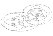
図17には、分散ビーコンを用いてネットワークが自律的に形成されている様子を示している。次隣接のMTを考慮したネットワークができるので。STA1にとっては、点線の楕円で示したSTA4以下の範囲がIBSSとみなされる。また、STA5にとっては、一点鎖線の楕円で示したSTA3以上の範囲がIBSSとみなされる。 FIG. 17 shows a state where a network is autonomously formed using distributed beacons. Because the network which considered MT of the next neighbor can be made. For STA1, a range below STA4 indicated by a dotted ellipse is regarded as IBSS. For STA5, a range of STA3 or more indicated by a dashed-dotted ellipse is regarded as IBSS.
以上によって隠れ端末問題を緩和すると同時に、ネットワークの動的変化への対応が可能となる。すなわち、ネットワークの移動によってビーコン位置が他のMTと重なってしまったMTのみが自局のビーコン位置TBTTを変更することにより、衝突の問題を解消することができる。 As a result, the hidden terminal problem can be alleviated, and at the same time, it is possible to cope with dynamic changes in the network. That is, only the MT whose beacon position overlaps with another MT due to the movement of the network changes its own beacon position TBTT, so that the collision problem can be solved.
分散ビーコンを用いたネットワークでは、動的なネットワークの構築が可能である。しかし、ネットワークの境界がMT毎に異なるため、すべてのMTが同じチャネルを利用することが前提となる。したがって、他のチャネルへの切り替えを行なう場合、IEEE802.11におけるアドホック・モードと同様に、すべてのMTがチャネルを一斉に切り替える必要がある。 In a network using distributed beacons, a dynamic network can be constructed. However, since the boundary of the network is different for each MT, it is assumed that all MTs use the same channel. Therefore, when switching to another channel, it is necessary for all MTs to switch channels simultaneously, as in the ad-hoc mode in IEEE 802.11.
また、すべてのMTが同じチャネルを利用し、所定の伝送フレーム周期間隔で同じ時間的位置(スロット)若しくは同じ帯域を繰り返し利用しているため、自分が認識していないMTから干渉を受けることがある。電波状況などによってその干渉が大きくなると、利用したいスロットが空いているにも拘らず、所要SINRを満たさないために送受信できなくなる。 In addition, since all MTs use the same channel and repeatedly use the same time position (slot) or the same band at a predetermined transmission frame period interval, they may receive interference from MTs that they do not recognize. is there. If the interference increases due to radio wave conditions or the like, transmission / reception cannot be performed because the required SINR is not satisfied even though the slot to be used is free.
この対策として、自局の送信電力を受信側の所要SINRを満たす最低限の電力に制御(送信電力制御)し、さらに、受信側ではプリアンブル検出のための閾値を変えることで、送受信間の信号到達範囲を制御し、干渉を低減する方法(すなわち、電力制御と閾値変更による送受信範囲の操作)が提案されている(例えば、特願2004−025506号明細書を参照のこと)。しかしながら、すべてのMTが同じチャネルを利用しているので、チャネル上に収容されている通信局数などによっては干渉の低減には限界がある。 As a countermeasure, the transmission power of the local station is controlled to the minimum power that satisfies the required SINR on the reception side (transmission power control), and the signal for transmission and reception is changed by changing the threshold for preamble detection on the reception side. There has been proposed a method of controlling the reach and reducing interference (that is, operation of a transmission / reception range by power control and threshold change) (see, for example, Japanese Patent Application No. 2004-025506). However, since all MTs use the same channel, there is a limit to reducing interference depending on the number of communication stations accommodated on the channel.
上記の分散ビーコンを用いたネットワークでは、1つのチャネルをデータ伝送の帯域を確保する最小単位であるスロット毎に分け、複数のスロットを1まとめにして伝送フレーム周期(すなわちスーパーフレーム)を構成している。そして、各MTは、スーパーフレーム毎にビーコンを送信し、自分が知りうる範囲(次隣接まで)のMTと重ならないスロットを自局のビーコン送信位置として選択している。スーパーフレーム長を固定(すなわちスーパーフレーム内のスロット数を固定)としているので、この最小のビーコン間隔によって、そのネットワークに参加できるMTの最大数はスーパーフレーム内のスロット数以下に決まってしまう。したがって、たとえスーパーフレームに未使用帯域(スロット)が残っていたとしても、MTの数が最大値に達している場合は新たなMTはそのネットワークに参加できないことになる. In the network using the distributed beacon described above, one channel is divided into slots, which are the minimum units for securing a data transmission band, and a plurality of slots are grouped to form a transmission frame period (ie, a super frame). Yes. Each MT transmits a beacon for each superframe, and selects a slot that does not overlap with an MT within a range that can be known by itself (up to the next neighbor) as a beacon transmission position of the local station. Since the superframe length is fixed (that is, the number of slots in the superframe is fixed), the maximum number of MTs that can participate in the network is determined by the minimum beacon interval to be equal to or less than the number of slots in the superframe. Therefore, even if an unused band (slot) remains in the superframe, if the number of MTs reaches the maximum value, a new MT cannot join the network.
次に、複数のネットワークがそれぞれ異なるチャネルを用いている場合について考える。図18には、複数のネットワークがそれぞれ異なるチャネルを使用している様子を示している。IBSS0とIBSS1は異なるチャネルを使用しているため干渉は発生しない。このような通信環境下で、新たなSTA6がそれらのネットワークに移動してきたものと仮定する。そして、この新規参入局STA6が図19に示す位置に存在し、既存局STA1及びSTA5の双方との通信を要望したとする。 Next, consider a case where a plurality of networks use different channels. FIG. 18 shows a state where a plurality of networks use different channels. Since IBSS0 and IBSS1 use different channels, no interference occurs. It is assumed that a new STA 6 has moved to these networks under such a communication environment. Then, it is assumed that this new entry station STA6 exists at the position shown in FIG. 19 and requests communication with both the existing stations STA1 and STA5.
STA6は、何れか一方のIBSSに参加しなければならない。このため、交互にIBSSへの参加と離脱を繰り返すか、若しくはすべてのMTを同じチャネルに切り替えなければならない。前者では、STA1とSTA6、及びSTA1とSTA5間のオーバーヘッドが大きくなる。後者では、直接関係のないMTまでチャネルを切り替えなければならなくなり、無駄な手続きが必要となる。 The STA 6 must participate in one of the IBSSs. For this reason, it is necessary to alternately join and leave the IBSS or switch all MTs to the same channel. In the former, the overhead between STA1 and STA6 and between STA1 and STA5 becomes large. In the latter case, it is necessary to switch channels to MTs that are not directly related, and wasteful procedures are required.
また、網目のように配置された多くのMTを有する自律分散ネットワークでは、ネットワークの境界が個々のMTで異なるため、従来のチャネル割当方式では複数のチャネルを有効に共用することが困難になる。 Further, in an autonomous distributed network having many MTs arranged like a mesh, since the boundary of the network is different for each MT, it is difficult to effectively share a plurality of channels with the conventional channel allocation method.
複数チャネルを利用した無線分散ネットワーク:
複数のチャネルが用意されている通信環境下において、同一のネットワークに属しながら通信局によって異なるビーコン送信チャネルを用いる通信システムについて提案されている(例えば、特願2003−281586号明細書、特願2003−315280号明細書を参照のこと)。これらの通信システムでは、チャネルの干渉状況に応じて送信チャネルを選択することにより、干渉を低減したアドホック・ネットワークを形成することが可能となる。
Wireless distributed network using multiple channels:
A communication system that uses a beacon transmission channel that belongs to the same network and uses different beacon transmission channels while belonging to the same network has been proposed (for example, Japanese Patent Application No. 2003-281586, Japanese Patent Application 2003). No. -315280). In these communication systems, it is possible to form an ad hoc network with reduced interference by selecting a transmission channel according to the channel interference situation.
例えば特願2003−281586号明細書では、各通信局は自分の受信に最適なチャネル上で他局のビーコンと重ならないようにビーコンを送信する。ビーコン送信後に優先送信権を得た通信局は、受信側の最適チャネルへ移行して送信を開始する。したがって、受信側で最適な干渉状況の下での通信が可能となっている。 For example, in the specification of Japanese Patent Application No. 2003-281586, each communication station transmits a beacon so as not to overlap with the beacon of another station on a channel optimal for its reception. The communication station that has obtained the priority transmission right after the beacon transmission shifts to the optimum channel on the receiving side and starts transmission. Therefore, it is possible to perform communication under optimum interference conditions on the receiving side.
一方、特願2003−315280号明細書では、各通信局は、周辺局が受けている干渉の平均レベルをチャネル毎に求め、その平均干渉レベルが最も低くなるチャネルを送信チャネルとして決定する。自局にとって優先度の高い周辺局の干渉に重み付けをしてチャネル毎の加重平均を求めることにより、自局から見て優先される周辺局にとって干渉の少ないチャネルが送信チャネルとして選択されるようになり、システム全体のスループットが向上する。 On the other hand, in the specification of Japanese Patent Application No. 2003-315280, each communication station obtains an average level of interference received by peripheral stations for each channel, and determines a channel having the lowest average interference level as a transmission channel. By calculating the weighted average for each channel by weighting the interference of peripheral stations with high priority for the own station, a channel with less interference is selected as the transmission channel for the peripheral stations prioritized when viewed from the local station. Thus, the throughput of the entire system is improved.
ここで、各通信局が移動するような環境や、人体などの遮蔽物の移動が頻繁に起こる環境を想定する。このような環境で複数チャネルを利用した無線分散通信システムを用いると、激しい伝搬変動のためにビーコン送信チャネルやデータ通信チャネルの変動も頻繁になる。このため、他の通信局から送信されるビーコンを受信するスキャン動作も頻繁に行なう必要が生じ、通信のオーバーヘッドが大きくなってしまうという問題が生じる。 Here, an environment in which each communication station moves or an environment in which a moving object such as a human body frequently moves is assumed. When a wireless distributed communication system using a plurality of channels is used in such an environment, fluctuations in the beacon transmission channel and data communication channel become frequent due to severe propagation fluctuations. For this reason, it is necessary to frequently perform a scanning operation for receiving a beacon transmitted from another communication station, resulting in a problem that communication overhead increases.
また、複数チャネルを用いた通信では、他の通信局のビーコンをスキャンするために、チャネル数分だけスキャンを繰り返す必要があるため、単一のチャネルを用いた通信システムと比べてオーバーヘッドが大きくなる。 Also, in communication using multiple channels, it is necessary to repeat scanning for the number of channels in order to scan beacons of other communication stations, so overhead is increased compared to a communication system using a single channel. .
本発明の目的は、制御局と被制御局の関係を有しないで各通信局がCSMAなどのキャリア検出若しくはメディア状態の監視に基づくランダム・アクセス動作を自律分散的に行なうことにより無線ネットワークを好適に構築することができる、優れた無線通信システム、無線通信装置及び無線通信方法、並びにコンピュータ・プログラムを提供することにある。 An object of the present invention is to make a wireless network suitable for each communication station by performing autonomous random access operation based on carrier detection such as CSMA or media status monitoring without having a relationship between a control station and a controlled station. It is an object of the present invention to provide an excellent wireless communication system, wireless communication apparatus and wireless communication method, and computer program that can be constructed.
本発明のさらなる目的は、複数の通信チャネルが用意されている通信環境下において、近隣の無線システムが干渉し合うことなく特定の制御局の介在なしに自律分散型の無線ネットワークを形成することができる、優れた無線通信システム、無線通信装置及び無線通信方法、並びにコンピュータ・プログラムを提供することにある。 A further object of the present invention is to form an autonomous decentralized wireless network without intervention of a specific control station without interfering with neighboring wireless systems in a communication environment where a plurality of communication channels are prepared. An excellent wireless communication system, a wireless communication apparatus, a wireless communication method, and a computer program are provided.
本発明のさらなる目的は、ネットワークへの負荷を少なくしつつ、通信チャネルの利用状況などに応じて各通信局が動的且つ自律的に通信チャネルを切り替えていく、マルチチャネル自律分散型の無線ネットワークを形成することができる、優れた無線通信システム、無線通信装置及び無線通信方法、並びにコンピュータ・プログラムを提供することにある。 A further object of the present invention is to provide a multi-channel autonomous decentralized wireless network in which each communication station dynamically and autonomously switches communication channels in accordance with the use status of communication channels while reducing the load on the network. An excellent wireless communication system, wireless communication apparatus and wireless communication method, and computer program can be provided.
本発明は、上記課題を参酌してなされたものであり、その第1の側面は、複数の通信チャネルが用意されている通信環境下において、通信局がランダム・アクセスを行なう無線通信システムであって、パケットを送信する通信局は、パケット単位で通信チャネルを割り当てることを特徴とする無線通信システムである。 The present invention has been made in consideration of the above problems, and a first aspect thereof is a wireless communication system in which a communication station performs random access in a communication environment in which a plurality of communication channels are prepared. Thus, a communication station that transmits a packet is a wireless communication system in which a communication channel is assigned in units of packets.
但し、ここで言う「システム」とは、複数の装置(又は特定の機能を実現する機能モジュール)が論理的に集合した物のことを言い、各装置や機能モジュールが単一の筐体内にあるか否かは特に問わない。 However, “system” here refers to a logical collection of a plurality of devices (or functional modules that realize specific functions), and each device or functional module is in a single housing. It does not matter whether or not.
無線通信システムでは、制御局となる装置を1台設けて、この制御局の統括的な制御下でネットワークを形成する方法が一般的であり、制御局の配下で、通信装置同士で情報伝送の衝突が生じないように帯域予約通信を行なう。ところが、制御局の介在が伴うことにより伝送路の利用効率が半減してしまうため、端末同士が直接非同期的に通信を行なう自律分散型の通信システムが考案されている。 In a wireless communication system, a method is generally used in which a single device serving as a control station is provided, and a network is formed under the overall control of the control station, and information transmission between communication devices is performed under the control station. Band reservation communication is performed so that no collision occurs. However, since the use efficiency of the transmission line is reduced by half due to the intervention of the control station, an autonomous distributed communication system in which terminals communicate with each other directly and asynchronously has been devised.
他方、同じ通信チャネルを使用する複数の独立したネットワーク間でビーコンやパケットの衝突が生じる可能性があるために、通信チャネルをあらかじめ複数用意しておくというマルチチャネル通信方式が採用される。通信中に他のシステムが割り込んだり、参入局数が多くなって帯域の余裕がなくなってきたりしたときに、使用する通信チャネルを選択して動作を開始することにより、ネットワーク動作を維持し、他のネットワークとの共存を実現することができる。 On the other hand, since there is a possibility of collision of beacons and packets between a plurality of independent networks using the same communication channel, a multi-channel communication method is adopted in which a plurality of communication channels are prepared in advance. When other systems interrupt during communication, or when the number of participating stations increases and there is no room for bandwidth, the network operation is maintained by selecting the communication channel to be used and starting the operation. Coexistence with other networks can be realized.
ところが、ネットワークで使用する通信チャネルを一斉に切り替えるためには、制御局の介在により利用チャネルの指示を行なう必要がある。言い換えれば、自律分散型のアドホック・ネットワークでは、複数の通信チャネルを利用したリソース管理は重要であるにも拘らず、制御局不在のために、通信チャネルを切り替えることが困難である。また、制御局の配下で動作するシステムにおいても、ネットワークの一部の干渉により、ネットワーク全体のチャネルを切り替える必要が生じるため、チャネル切り替えに伴うネゴシエーションが増加してスループットが低下してしまう。 However, in order to switch the communication channels used in the network all at once, it is necessary to instruct the use channel through the intervention of the control station. In other words, in an autonomous decentralized ad hoc network, although resource management using a plurality of communication channels is important, it is difficult to switch communication channels due to the absence of a control station. Further, even in a system operating under the control of a control station, it is necessary to switch the channel of the entire network due to a part of the interference of the network. Therefore, negotiation associated with channel switching increases and throughput decreases.
従来のマルチチャネル通信システムでは、同一の周波数チャネル又は符号チャネルで通信チャネルを構成し、1つの通信局群で同一の通信チャネルを割り当てるという運用方法が多い。これに対し、本発明に係る無線通信システムでは、パケットを送信する通信局は、パケット単位で通信チャネルを割り当てる。そして、使用する通信チャネルを検出できるようにパケットのプリアンブル・パターンを構成するようにした。これにより、送信局がパケット単位で動的にチャネルを選択しても、受信局はパケット単位でこれに追従することができる。また、パケット単位での通信チャネルの動的な切り替えにより、通信可能な通信局数を増やすことが可能となる。 In a conventional multi-channel communication system, there are many operation methods in which a communication channel is configured by the same frequency channel or code channel, and the same communication channel is allocated by one communication station group. On the other hand, in the wireless communication system according to the present invention, a communication station that transmits a packet assigns a communication channel in units of packets. Then, the preamble pattern of the packet is configured so that the communication channel to be used can be detected. As a result, even if the transmitting station dynamically selects a channel on a packet basis, the receiving station can follow this on a packet basis. In addition, the number of communication stations that can communicate can be increased by dynamically switching communication channels in units of packets.
自律分散型の無線通信システムでは、各通信局はビーコン情報を報知することにより、ネットワーク構成を通知し合うとともに緩やかに時間同期して、時分割多重アクセス構造を持った伝送(MAC)フレームによりチャネル・リソースを効果的に利用した伝送制御が行なう。本発明によれば、ビーコンやパケットの受信局では、送信チャネルに関する情報を事前に知らなくてもチャネル切り替えに追従することができることから、ビーコン送信に使用する通信チャネルとは無関係に、パケット送信に使用する通信チャネルを個別に割り当てることができる。 In an autonomous decentralized wireless communication system, each communication station broadcasts beacon information, notifies each other of the network configuration, and synchronizes slowly with time, and uses a transmission (MAC) frame having a time-division multiple access structure as a channel.・ Transmission control using resources effectively. According to the present invention, a beacon or packet receiving station can follow channel switching without knowing information about a transmission channel in advance, so that it can transmit packets regardless of the communication channel used for beacon transmission. The communication channel to be used can be individually assigned.
このように、パケット単位で通信チャネルを割り当てる場合、送信局がパケット単位で動的にチャネルを選択しても、受信局はパケット単位でこれに追従できるようにしなければならない。そこで、本発明では、送信局はパケットのプリアンブル部に通信チャネルの識別情報を含ませ、受信局はプリアンブル部を検出してパケット単位での通信チャネルの切り替えに追従できるようにしている。 As described above, when a communication channel is allocated in units of packets, the receiving station must be able to follow this in units of packets even if the transmitting station dynamically selects a channel in units of packets. Therefore, in the present invention, the transmitting station includes the identification information of the communication channel in the preamble part of the packet, and the receiving station detects the preamble part so as to follow the switching of the communication channel in packet units.
本発明に係る無線ネットワークでは、同じ周波数帯を利用し、拡散符号の相違により分離される複数の通信チャネルを用いてマルチチャネル・システムを構成することができる。 In the wireless network according to the present invention, a multi-channel system can be configured by using a plurality of communication channels that use the same frequency band and are separated by the difference in spreading codes.
この場合、受信局は、各通信チャネルに相当する拡散符号との相関を並列的に求め、各相関値との閾値比較に基づいてプリアンブルを検出し、受信パケットが使用する通信チャネルを判定することにより、パケット単位での通信チャネルの切り替えに追従することができる。 In this case, the receiving station obtains the correlation with the spreading code corresponding to each communication channel in parallel, detects the preamble based on the threshold comparison with each correlation value, and determines the communication channel used by the received packet. Thus, it is possible to follow switching of communication channels in units of packets.
あるいは、本発明に係る無線ネットワークでは、パケットのプリアンブル部送信用の制御チャネルと、パケットのデータ部送信用のデータ・チャネルを設けるようにしてもよい。制御チャネルは単一の周波数帯で構成される。これに対し、データチャネルは、周波数帯の相違により分離される複数の周波数チャネルで構成されるマルチチャネルである。 Alternatively, in the wireless network according to the present invention, a control channel for transmitting the preamble part of the packet and a data channel for transmitting the data part of the packet may be provided. The control channel is composed of a single frequency band. On the other hand, the data channel is a multi-channel composed of a plurality of frequency channels separated by the difference in frequency band.
この場合、送信局は、データ・チャネルにおいて使用する周波数チャネルと1対1で対応する拡散符号で拡散したプリアンブル・パターンを送信した後、該拡散符号に対応する周波数帯からなるデータ・チャネルにおいてパケットのデータ部を送信する。プリアンブル・パターンは、周波数チャネルに対応する拡散符号により決められたものとなる。したがって、受信局は、データ・チャネルとして利用される各周波数帯と1対1で対応する拡散符号とプリアンブル・パターンとの相関を並列的に求め、各相関値との閾値比較に基づいて拡散符号を検出することにより、パケット単位での通信チャネルの切り替えに追従することができる。そして、検出した拡散符号に相当する周波数チャネルでパケットのデータ部を受信処理することができる。 In this case, the transmitting station transmits a preamble pattern spread with a spreading code corresponding to the frequency channel used in the data channel on a one-to-one basis, and then transmits a packet in the data channel having a frequency band corresponding to the spreading code. Send the data part of The preamble pattern is determined by the spreading code corresponding to the frequency channel. Therefore, the receiving station obtains the correlation between the spread code and the preamble pattern corresponding to each frequency band used as a data channel in a one-to-one manner in parallel, and based on the threshold comparison with each correlation value, the spread code By detecting this, it is possible to follow the switching of the communication channel in packet units. The data portion of the packet can be received and processed using the frequency channel corresponding to the detected spreading code.
あるいは、本発明に係る無線ネットワークでは、利用可能な複数の直交分離チャネルをシンボル毎に切り替える固有のホッピング・パターンにより通信チャネルを定義し、複数の直交分離チャネルにおけるホッピング・パターンの相違により分離される複数の通信チャネルによりマルチチャネルを構成することができる。 Alternatively, in the wireless network according to the present invention, a communication channel is defined by a unique hopping pattern for switching a plurality of orthogonal separation channels that can be used for each symbol, and the communication channels are separated by a difference in hopping patterns in the plurality of orthogonal separation channels. A multi-channel can be configured by a plurality of communication channels.
例えば、周波数ホッピング系列により通信チャネルを構成することができる。但し、ここで言う直交分離チャネルは、周波数の相違で分離される周波数チャネル以外にも、拡散符号の相違により直交可能な符号チャネルや空間直交された空間チャネルなどが挙げられ、ホッピングを行なうためのチャネル分離の方法は特に限定されない。 For example, a communication channel can be configured by a frequency hopping sequence. However, the orthogonal separation channel mentioned here includes not only the frequency channel separated by the difference in frequency, but also a code channel that can be orthogonalized by a difference in spreading code, a spatial channel that is spatially orthogonalized, etc. The channel separation method is not particularly limited.
直交分離チャネルのホッピング・パターンによりチャネルを分離してマルチチャネルを構成する通信システムでは、パケットを送信する通信局は、パケットのプリアンブル部を、データ部と同じホッピング・パターンで伝送するようにする。そして、パケットの受信局でパケット毎の通信チャネル(すなわち、ホッピング・パターン)の切り替わりに追従できるように、送信局からは、ホッピング・パターンと1対1で対応するプリアンブル・パターンを、少なくとも基本となる1つの直交分離チャネル上で送信するようにする。 In a communication system in which channels are separated by a hopping pattern of orthogonal separation channels to form a multi-channel, a communication station that transmits a packet transmits a preamble portion of the packet with the same hopping pattern as that of the data portion. Then, in order for the receiving station of the packet to follow the switching of the communication channel (that is, hopping pattern) for each packet, the transmitting station has at least a preamble pattern corresponding to the hopping pattern at least as basic. To transmit on one orthogonal separation channel.
このような場合、パケットを受信する通信局は、プリアンブル部では直交分離チャネルをホッピングせず、基本となる1つの直交分離チャネル上で受信して得られるプリアンブル・パターンに基づいてホッピング・パターンを識別することができる。そして、以後のデータ部では、識別されたホッピングを行なうことでデータの受信並びに復調が可能となる。 In such a case, the communication station that receives the packet does not hop the orthogonal separation channel in the preamble part, but identifies the hopping pattern based on the preamble pattern obtained on one basic orthogonal separation channel. can do. In the subsequent data portion, data can be received and demodulated by performing the identified hopping.
例えば、パケットを送信する通信局は、ホッピング・パターン(すなわち通信チャネル)に1対1で対応する拡散符号によって決められるプリアンブル・パターンを前記1つの直交分離チャネル上で送信する。この場合、パケットを受信する通信局は、プリアンブル部を受信するときに、プリアンブル・パターンと各ホッピング・パターンに相当する拡散符号との相関を並列的に求め、各相関値との閾値比較に基づいて拡散符号を検出する。そして、検出した拡散符号に相当するホッピング・パターンに従ってパケットのデータ部を受信処理することができる。 For example, a communication station that transmits a packet transmits a preamble pattern determined by a spreading code that has a one-to-one correspondence with a hopping pattern (that is, a communication channel) on the one orthogonal separation channel. In this case, when receiving the preamble part, the communication station that receives the packet obtains the correlation between the preamble pattern and the spreading code corresponding to each hopping pattern in parallel, and based on threshold comparison with each correlation value. To detect the spreading code. The data portion of the packet can be received and processed according to the hopping pattern corresponding to the detected spreading code.
あるいは、パケットを送信する通信局は、すべての通信チャネルで共通の拡散符号を用いてプリアンブル・パターンを決定し、少なくとも1つの直交分離チャネル上において各シンボルのプリアンブル・パターンに通信チャネルを識別する情報を重畳する。情報を重畳する方法としては、BPSKなどの位相変調を利用することができる。この場合、受信側で用意すべき拡散符号の相関器を1つにすることが可能となる。そして、通信チャネルの分離はプリアンブル・パターンに信号を重畳することで実現する。すなわち、前記1つの直交分離チャネル上で、シンボル毎の前記共通の拡散符号との相関値を累積加算していくことで、通信チャネルを分離することができる。 Alternatively, a communication station that transmits a packet determines a preamble pattern using a common spreading code in all communication channels, and identifies the communication channel in the preamble pattern of each symbol on at least one orthogonal separation channel Is superimposed. As a method for superimposing information, phase modulation such as BPSK can be used. In this case, it is possible to have one spread code correlator to be prepared on the receiving side. Communication channel separation is realized by superimposing a signal on a preamble pattern. That is, the communication channel can be separated by accumulating the correlation values with the common spreading code for each symbol on the one orthogonal separation channel.
上述したように、通信局が各通信チャネルに対応したプリアンブル部を検出する複数のプリアンブル検出部を備えている場合、これらのプリアンブル検出器を並列的に動作させて受信待機し、最も早く検出できたプリアンブル部に対応する通信チャネルにおけるパケットの受信動作を起動するようにしてもよい。この場合、受信パケットのチャネル情報が未知の場合には、時間的にパケットが重なったときには、最も早く検出されたパケットが受信対象となる。 As described above, when the communication station has a plurality of preamble detectors that detect the preamble corresponding to each communication channel, these preamble detectors are operated in parallel to wait for reception and can be detected earliest. Alternatively, the packet reception operation on the communication channel corresponding to the preamble portion may be activated. In this case, when the channel information of the received packet is unknown, when the packets overlap with each other in time, the earliest detected packet becomes the reception target.
上述したように、本発明によれば、各通信局がランダム・アクセスを行なう場合において、パケット単位で通信チャネルを切り替えることができ、パケットの受信局では、送信チャネルに関する情報を事前に知らなくてもチャネル切り替えに追従することができる。 As described above, according to the present invention, when each communication station performs random access, the communication channel can be switched on a packet-by-packet basis, and the packet receiving station does not know information on the transmission channel in advance. Can also follow channel switching.
この場合、チャネル切り替えに伴う通信局間のネゴシエーションはなく、チャネル切り替えに伴いシステムのスループットが低下することはない。また、チャネル切り替えにより、ネットワーク同士の衝突を回避しながら、より多くの通信局をシステムに収容することができる。また、パケットの受信局は、パケットのプリアンブル部で通信チャネルを識別できることから、周辺局がビーコン信号の送信に利用するチャネルを検出するためのスキャン動作を行なう必要がない。 In this case, there is no negotiation between communication stations associated with channel switching, and system throughput does not decrease with channel switching. Also, by switching channels, more communication stations can be accommodated in the system while avoiding collisions between networks. Further, since the packet receiving station can identify the communication channel by the preamble part of the packet, it is not necessary to perform a scanning operation for detecting the channel used by the peripheral station for transmitting the beacon signal.
また、本発明に係るマルチチャネル通信システムにおいて、通信局同士で、各通信方向で使用する通信チャネルを事前に選択するようにしてもよい。例えば、複数の通信チャネルの空き情報や、他の通信チャネルにおける干渉量に基づいて、通信チャネルを事前に切り替えるようにする。通信相手と通信チャネル並びに帯域をあらかじめ決定しておけば、パケットを受信する通信局では、動作させるべきプリアンブル検出器の数を減らすことが可能となり、消費電力を低減することができる。また、異なる通信チャネルを利用する複数のネットワークが交錯する通信環境下であっても、新規参入局は、いずれのネットワークの通信局と通信を行なうかに応じて通信チャネルを切り替えることで、柔軟に対応することが可能となる。 In the multi-channel communication system according to the present invention, communication stations used in each communication direction may be selected in advance between communication stations. For example, the communication channels are switched in advance based on the availability information of a plurality of communication channels and the amount of interference in other communication channels. If the communication partner, the communication channel, and the bandwidth are determined in advance, the communication station that receives the packet can reduce the number of preamble detectors to be operated, thereby reducing the power consumption. In addition, even in a communication environment where multiple networks using different communication channels are intermingled, a new entry station can flexibly switch the communication channel according to which communication station it communicates with. It becomes possible to respond.
また、通信局同士で通信チャネル並びに使用する帯域を事前に決定するようにしてもよい。この場合、パケットを受信する通信局は、該事前に決定された帯域において、該事前に決定された通信チャネル上でのみプリアンブル検出を行なうことにより、所望のパケットを受信することができる。 Further, the communication channel and the band to be used may be determined in advance between the communication stations. In this case, the communication station that receives the packet can receive the desired packet by performing preamble detection only on the predetermined communication channel in the predetermined band.
また、パケットを送信する通信局は、所要SINRを満たす最小の電力でパケットを送信するように送信電力制御を行なうようにしてもよい。一方のパケットを受信する通信局は、プリアンブル検出時の閾値を調整し、希望のパケットのみ検出し、干渉となるパケットのプリアンブルを検出しないようにしてもよい。この場合、所要SINRを満たし易くなり、通信局Aと通信局B間の通信が可能になる。すなわち、通信チャネルの動的割当てを行なう場合の干渉量を低減することができる。 The communication station that transmits the packet may perform transmission power control so that the packet is transmitted with the minimum power that satisfies the required SINR. The communication station that receives one of the packets may adjust the threshold at the time of detecting the preamble, detect only the desired packet, and not detect the preamble of the packet that causes interference. In this case, the required SINR is easily satisfied, and communication between the communication station A and the communication station B becomes possible. That is, the amount of interference when performing dynamic allocation of communication channels can be reduced.
また、本発明の第2の側面は、複数の通信チャネルが用意されている通信環境下で通信動作を行なうための処理をコンピュータ・システム上で実行するようにコンピュータ可読形式で記述されたコンピュータ・プログラムであって、
パケット送信用の通信チャネルをパケット単位で割り当てる通信チャネル設定ステップと、
該設定した通信チャネルの識別情報を含んだプリアンブル部を付加したパケットを該設定した通信チャネル上で送信するパケット送信ステップと、
受信したパケットのプリアンブル部を検出するプリアンブル検出ステップと、
プリアンブル部の検出結果に基づいてパケットを受信する通信チャネルに切り替えてパケットのデータ部を受信するパケット受信ステップと、
を具備することを特徴とするコンピュータ・プログラムである。
According to a second aspect of the present invention, there is provided a computer program described in a computer-readable format so that a process for performing a communication operation in a communication environment in which a plurality of communication channels are prepared is executed on a computer system. A program,
A communication channel setting step for assigning a communication channel for packet transmission in units of packets;
A packet transmission step of transmitting a packet to which a preamble portion including identification information of the set communication channel is added on the set communication channel;
A preamble detection step for detecting a preamble portion of the received packet;
A packet receiving step of switching to a communication channel for receiving a packet based on the detection result of the preamble portion and receiving the data portion of the packet;
A computer program characterized by comprising:
本発明の第2の側面に係るコンピュータ・プログラムは、コンピュータ・システム上で所定の処理を実現するようにコンピュータ可読形式で記述されたコンピュータ・プログラムを定義したものである。換言すれば、本発明の第2の側面に係るコンピュータ・プログラムをコンピュータ・システムにインストールすることによってコンピュータ・システム上では協働的作用が発揮され、無線通信装置として動作する。このような無線通信装置を複数起動して無線ネットワークを構築することによって、本発明の第1の側面に係る無線通信システムと同様の作用効果を得ることができる。 The computer program according to the second aspect of the present invention defines a computer program described in a computer-readable format so as to realize predetermined processing on a computer system. In other words, by installing the computer program according to the second aspect of the present invention in the computer system, a cooperative action is exhibited on the computer system, and it operates as a wireless communication device. By activating a plurality of such wireless communication devices to construct a wireless network, it is possible to obtain the same effects as the wireless communication system according to the first aspect of the present invention.
本発明によれば、制御局と被制御局の関係を有しないで各通信局がCSMAなどのキャリア検出若しくはメディア状態の監視に基づくランダム・アクセス動作を自律分散的に行なうことにより無線ネットワークを好適に構築することができる、優れた無線通信システム、無線通信装置及び無線通信方法、並びにコンピュータ・プログラムを提供することができる。 According to the present invention, it is preferable to use a wireless network without autonomously distributing random access operations based on carrier detection such as CSMA or media state monitoring without communication between the control station and the controlled station. It is possible to provide an excellent wireless communication system, wireless communication apparatus, wireless communication method, and computer program that can be constructed.
また、本発明によれば、複数の通信チャネルが用意されている通信環境下において、近隣の無線システムが干渉し合うことなく特定の制御局の介在なしに自律分散型の無線ネットワークを形成することができる、優れた無線通信システム、無線通信装置及び無線通信方法、並びにコンピュータ・プログラムを提供することができる。 In addition, according to the present invention, in a communication environment in which a plurality of communication channels are prepared, an autonomous distributed wireless network can be formed without interference of a specific control station without interference of neighboring wireless systems. An excellent wireless communication system, wireless communication apparatus and wireless communication method, and computer program can be provided.
また、本発明によれば、ネットワークへの負荷を少なくしつつ、通信チャネルの利用状況などに応じて各通信局が動的且つ自律的に通信チャネルを切り替えていきながら、マルチチャネル自律分散型の無線ネットワークを形成することができる、優れた無線通信システム、無線通信装置及び無線通信方法、並びにコンピュータ・プログラムを提供することができる。 In addition, according to the present invention, while reducing the load on the network, each communication station dynamically and autonomously switches the communication channel according to the usage status of the communication channel. An excellent wireless communication system, wireless communication apparatus, wireless communication method, and computer program capable of forming a wireless network can be provided.
本発明によれば、ネットワークの境界があいまいとなる自律分散無線ネットワークにおいて、複数のチャネルを共用することが容易になる。 According to the present invention, it becomes easy to share a plurality of channels in an autonomous distributed wireless network in which the boundary of the network is ambiguous.
また、本発明によれば、チャネルの利用状況や、他チャネルからの干渉量を基に、ビーコン送信チャネルと無関係にデータ送信チャネルを動的に割り当てることで、被干渉量を減らすことができる。 Further, according to the present invention, the amount of interference can be reduced by dynamically assigning the data transmission channel regardless of the beacon transmission channel based on the channel usage status and the interference amount from other channels.
また、本発明によれば、ネットワークの移動や新たな通信局の発生に伴うネットワークの動的な変動に対し、必要最小限の通信局のみがチャネルを切り替えることにより衝突の問題を解消することが可能となり、不要なチャネル切り替え作業が軽減される。 In addition, according to the present invention, it is possible to solve the collision problem by switching the channel of only the minimum necessary communication station against the dynamic change of the network accompanying the movement of the network or the generation of a new communication station. This makes it possible to reduce unnecessary channel switching work.
また、本発明によれば、送信局はパケット単位で動的にチャネルを選択しても受信局はこれに追従することができる。したがって、パケット単位でのチャネルの動的な切り替えにより通信可能な通信局数を増やすことが可能となる。 Further, according to the present invention, even if the transmitting station dynamically selects a channel on a packet basis, the receiving station can follow this. Therefore, it is possible to increase the number of communicable communication stations by dynamically switching channels in packet units.
また、本発明によれば、複数のチャネルを使用したパケットのプリアンブル部分のみを同一の周波数チャネルとし、符号やホッピング・パターンによってチャネルを識別子とすることで、複数チャネルのパケット検出が容易となる。また、分散ビーコン・システムにおいて、周辺局同士で同じ時刻(スロット)に複数のビーコンを配置しないという制限を加えた場合には、ビーコンを探索するスキャン動作も1チャネル分だけ行えば良いことになる。 Further, according to the present invention, only the preamble portion of a packet using a plurality of channels is set to the same frequency channel, and the channel is used as an identifier by a code or a hopping pattern, thereby facilitating packet detection of the plurality of channels. Further, in the distributed beacon system, when a restriction is imposed that a plurality of beacons are not arranged at the same time (slot) between neighboring stations, a scan operation for searching for a beacon only needs to be performed for one channel. .
また、本発明によれば、通信局は、複数のプリアンブル・パターンをそれぞれ検出する検出器を並列的に動作させることで、最もSINRの大きなパケットのみを選択的に受信することが可能となる。 Also, according to the present invention, the communication station can selectively receive only the packet having the largest SINR by operating in parallel the detectors that detect a plurality of preamble patterns.
また、本発明によれば、送信側が利用するチャネルとスロットをあらかじめ受信側に伝えておくことで、異なるチャネルのパケットが時間的に衝突した場合であっても、受信SINRが要求を満たせば選択的にいずれかのパケットを受信することが可能となる。 In addition, according to the present invention, the channel and slot used by the transmission side are communicated to the reception side in advance, so that even if packets of different channels collide in time, the selection can be made if the reception SINR satisfies the request. Thus, any packet can be received.
本発明のさらに他の目的、特徴や利点は、後述する本発明の実施形態や添付する図面に基づくより詳細な説明によって明らかになるであろう。 Other objects, features, and advantages of the present invention will become apparent from more detailed description based on embodiments of the present invention described later and the accompanying drawings.
以下、図面を参照しながら本発明の実施形態について詳解する。 Hereinafter, embodiments of the present invention will be described in detail with reference to the drawings.
本発明において想定している通信の伝搬路は無線であり、且つ複数の通信チャネルすなわちマルチチャネルからなる伝送媒体を用いて、複数の通信局間でネットワークを構築する。本発明で想定している通信は蓄積交換型のトラヒックであり、パケット単位で情報が転送される。 The propagation path of communication assumed in the present invention is wireless, and a network is constructed between a plurality of communication stations using a transmission medium composed of a plurality of communication channels, that is, multichannels. The communication assumed in the present invention is a storage and exchange type traffic, and information is transferred in units of packets.
従来のマルチチャネル通信システムでは、同一の周波数チャネル又は符号チャネルで通信チャネルを構成し、1つの通信局群で同一の通信チャネルを割り当てるということが多い。これに対し、本発明に係る無線通信システムでは、パケット単位で通信チャネルを動的に割り当てることにより、通信可能な通信局数を増やすことが可能となる。 In a conventional multi-channel communication system, a communication channel is often configured with the same frequency channel or code channel, and the same communication channel is assigned to one communication station group. In contrast, in the wireless communication system according to the present invention, it is possible to increase the number of communicable communication stations by dynamically allocating communication channels in units of packets.
本発明では、使用する通信チャネルを検出できるようにパケットのプリアンブル・パターンを構成するようにしている。これにより、送信局がパケット単位で動的にチャネルを選択しても、受信局はパケット単位でこれに追従することができる。受信局はこれに追従することができる(後述)。 In the present invention, a preamble pattern of a packet is configured so that a communication channel to be used can be detected. As a result, even if the transmitting station dynamically selects a channel on a packet basis, the receiving station can follow this on a packet basis. The receiving station can follow this (described later).
本発明に係る無線ネットワークでは、各通信局は、CSMAに基づくアクセス手順に従い直接(ランダム)に情報を伝送し、自律分散型の無線ネットワークを構築することができる。 In the wireless network according to the present invention, each communication station can directly (randomly) transmit information according to an access procedure based on CSMA, and construct an autonomous distributed wireless network.
制御局と被制御局の関係を有しない自律分散型の無線通信システムでは、例えば、各通信局はビーコン情報を報知することにより、近隣(すなわち通信範囲内)の他の通信局に自己の存在を知らしめるとともに、ネットワーク構成を通知する。また、ある通信局の通信範囲に新規に出現した通信局は、ビーコン信号を受信することにより、通信範囲に突入したことを検知するとともに、ビーコンに記載されている情報を解読することによりネットワーク認識し、ネットワークに参入することができる。 In an autonomous decentralized wireless communication system that does not have a relationship between a control station and a controlled station, for example, each communication station broadcasts beacon information, so that other communication stations in the vicinity (that is, within the communication range) are self-existing. And notify the network configuration. In addition, a communication station that newly appears in the communication range of a certain communication station detects that it has entered the communication range by receiving a beacon signal, and recognizes the network by decoding the information described in the beacon. And can enter the network.
本発明に係る無線ネットワークでは、通信局同士のビーコン信号の交換により互いに緩やかに時間同期して、時分割多重アクセス構造を持った伝送(MAC)フレームによりチャネル・リソースを効果的に利用した伝送制御が行なわれる。したがって、各通信局は、自律動作しながらも、周辺局に対し帯域を予約する、あるいは優先利用期間を設定するなど時間同期をベースにしたアクセス方式を行なうことができる。 In the wireless network according to the present invention, transmission control that effectively utilizes channel resources by transmission (MAC) frames having a time division multiple access structure that is time-synchronized gradually by exchanging beacon signals between communication stations. Is done. Accordingly, each communication station can perform an access method based on time synchronization, such as reserving a band for a peripheral station or setting a priority use period, while autonomously operating.
以下に説明する各通信局での処理は、基本的にはネットワークに参入するすべての通信局で実行される処理である。但し、場合によっては、ネットワークを構成するすべての通信局が、以下に説明する処理を実行するとは限らない。 The processing in each communication station described below is basically processing executed in all communication stations that enter the network. However, depending on the case, not all communication stations configuring the network execute the processing described below.
A.無線通信装置の構成
図1には、本発明の一実施形態に係る無線ネットワークにおいて通信局として動作する無線通信装置100の機能構成を模式的に示している。図示の無線通信装置100は、複数の通信チャネルが用意されている通信環境下において、同じ無線システム内では効果的にチャネル・アクセスを行なうことにより、他の無線システムと干渉し合うことなく適当なアドホック・ネットワークを形成することができる。
A. Configuration of Wireless Communication Device FIG. 1 schematically shows a functional configuration of a wireless communication device 100 that operates as a communication station in a wireless network according to an embodiment of the present invention. The illustrated wireless communication apparatus 100 performs appropriate channel access within the same wireless system in a communication environment in which a plurality of communication channels are prepared, so that the wireless communication apparatus 100 is suitable without interfering with other wireless systems. An ad hoc network can be formed.
無線通信装置100は、インターフェース101と、データ・バッファ102と、中央制御部103と、ビーコン生成部104と、制御信号生成部105と、無線送信部106と、タイミング制御部107と、チャネル設定部108と、アンテナ109と、無線受信部110と、制御信号解析部111と、ビーコン解析部112と、情報記憶部113とで構成される。
The wireless communication apparatus 100 includes an interface 101, a data buffer 102, a central control unit 103, a beacon generation unit 104, a control signal generation unit 105, a wireless transmission unit 106, a timing control unit 107, and a channel setting unit. 108, an antenna 109, a
インターフェース101は、この無線通信装置100に接続される外部機器(例えば、パーソナル・コンピュータ(図示しない)など)との間で各種情報の交換を行なう。 The interface 101 exchanges various types of information with an external device (for example, a personal computer (not shown)) connected to the wireless communication apparatus 100.
データ・バッファ102は、インターフェース101経由で接続される機器から送られてきたデータや、無線伝送路経由で受信したデータをインターフェース101経由で送出する前に一時的に格納しておくために使用される。 The data buffer 102 is used to temporarily store data sent from a device connected via the interface 101 and data received via the wireless transmission path before sending the data via the interface 101. The
中央制御部103は、送信パケットの生成や受信パケットの解析を始めとする無線通信装置100における一連の情報送信並びに受信処理の管理、伝送路のアクセス制御(マルチチャネルにおけるスキャン設定動作やチャネル設定動作、ビーコン受信動作、RTS/CTS方式に則ったデータ通信動作などを含む)などを通信機としての動作制御を一元的に行なう。 The central control unit 103 manages a series of information transmission and reception processing in the wireless communication apparatus 100 including generation of transmission packets and analysis of reception packets, transmission path access control (scan setting operation and channel setting operation in multi-channels). Operation control as a communication device is performed centrally, including beacon reception operation and data communication operation in accordance with the RTS / CTS system).
ビーコン生成部104は、近隣にある無線通信装置との間で周期的に交換されるビーコン信号を生成する。 The beacon generation unit 104 generates a beacon signal that is periodically exchanged with a nearby wireless communication device.
制御信号生成部105は、データ送信に先立ち、必要に応じて送信要求(RTS)信号や確認通知(CTS)信号などの制御情報を生成する。 Prior to data transmission, the control signal generation unit 105 generates control information such as a transmission request (RTS) signal and a confirmation notification (CTS) signal as necessary.
アンテナ109は、信号を選択された通信チャネル上で他の無線通信装置宛てに無線送信し、あるいは他の無線通信装置から送られる信号を収集する。本実施形態では、単一のアンテナを備え、送受信をともに並行しては行なえないものとする。また、同時刻に複数の通信チャネルをハンドルすることはできないものとする。 The antenna 109 wirelessly transmits a signal to another wireless communication device on the selected communication channel, or collects a signal transmitted from the other wireless communication device. In this embodiment, it is assumed that a single antenna is provided and that transmission and reception cannot be performed in parallel. Also, it is assumed that a plurality of communication channels cannot be handled at the same time.
無線送信部106は、送信信号を所定の変調方式で変調する変調器や、パケットのプリアンブル部の付加、デジタル送信信号をアナログ信号に変換するD/A変換器などのPHY部と、アナログ送信信号を周波数変換してアップコンバートするアップコンバータ、アップコンバートされた送信信号の電力を増幅するパワーアンプ(PA)などのRF部(いずれも図示しない)を含み、データ・バッファ102に一時格納されているデータやビーコン信号などを所定の伝送レートにて無線送信する。 The wireless transmission unit 106 includes a PHY unit such as a modulator that modulates a transmission signal with a predetermined modulation method, a preamble portion of a packet, a D / A converter that converts a digital transmission signal into an analog signal, and an analog transmission signal. Including an RF converter (not shown) such as an up-converter that converts the frequency of the signal and up-converts the power of the up-converted transmission signal, and is temporarily stored in the data buffer 102 Data and beacon signals are transmitted wirelessly at a predetermined transmission rate.
無線受信部110は、アンテナ109を介して他局から受信した信号を電圧増幅する低雑音アンプ(LNA)や、電圧増幅された受信信号を周波数変換によりダウンコンバートするダウンコンバータ、自動利得制御器(AGC)などのRF部と、アナログ受信信号をデジタル変換するA/D変換器、パケットのプリアンブル部の検出、同期獲得のための同期処理やチャネル推定、所定の復調方式により復調処理する復調器などのPHY部(いずれも図示しない)で構成され、所定の時間に他の無線通信装置から送られてきた情報やビーコンなどの信号を受信処理する。
The
図2には、無線受信部110の機能構成を模式的に示している。図示の例では、無線受信部110は、プリアンブル検出部110−1と、同期獲得及び保持部110−2と、データ復調部110−3で構成される。プリアンブル検出部110−1は、受信フレームの先頭のプリアンブル部分を検出する。同期獲得及び保持部110−2は、このプリアンブル検出結果を基に、受信フレームの同期を獲得し、これをデータ復調部110−3に出力する。そして、データ復調部110−3は、獲得した同期に従って、ヘッダ部以降の受信信号の復調処理を行なう。
FIG. 2 schematically illustrates a functional configuration of the
無線送信部106及び無線受信部110における無線送受信方式は、例えば無線ネットワークに適用可能な、比較的近距離の通信に適した各種の通信方式を適用することができる。具体的には、UWB(Ultra Wide Band)方式、OFDM(Orthogonal Frequency Division Multiplexing:直交周波数分割多重)方式、CDMA(Code Division Multiple Access:符号分割多元接続)方式などを採用することができる。
As a wireless transmission / reception method in the wireless transmission unit 106 and the
タイミング制御部107は、無線信号を送信並びに受信するためのタイミングの制御を行なう。例えば、自局のビーコン送信タイミングや周辺局からのビーコン受信タイミング、各通信チャネルにおけるスキャン動作周期、RTS/CTS方式に則った各パケット(RTS、CTS、データ、ACKなど)の送信タイミング(フレーム間スペース(IFS))などを制御する。 The timing control unit 107 controls timing for transmitting and receiving radio signals. For example, the transmission timing of each packet (RTS, CTS, data, ACK, etc.) in accordance with the RTS / CTS method, the beacon transmission timing of the own station, the beacon reception timing from the peripheral station, the scanning operation cycle in each communication channel Space (IFS)) and the like.
チャネル設定部108は、マルチチャネル方式の無線信号を実際に送受信する通信チャネルを選択する。本実施形態では、パケット単位で通信チャネルを切り替えることができる。 The channel setting unit 108 selects a communication channel that actually transmits and receives a multi-channel radio signal. In this embodiment, the communication channel can be switched on a packet basis.
制御信号解析部111は、周辺の無線通信装置から送られてきたRTS信号やCTS信号などの制御情報を解析する。 The control signal analysis unit 111 analyzes control information such as an RTS signal and a CTS signal transmitted from a peripheral wireless communication device.
ビーコン解析部112は、周辺局から受信したビーコン信号を解析し、近隣の無線通信装置の存在などを解析し、得られた情報を近隣装置情報として情報記憶部113に格納する。
The beacon analysis unit 112 analyzes a beacon signal received from a peripheral station, analyzes the presence of a neighboring wireless communication device, and stores the obtained information in the
情報記憶部113は、中央制御部103において実行される一連のアクセス制御動作などの実行手順命令や、自己のビーコン送信タイミングやビーコン送信チャネル、他の通信局のビーコン送信タイミングやビーコン送信チャネルなどのマルチチャネル情報、近隣装置情報などを蓄えておく。
The
B.プリアンブル・パターンの構成方法
本発明では、パケット単位で通信チャネルを割り当てる。そして、使用する通信チャネルを検出できるようにパケットのプリアンブル・パターンを構成することにより、送信局がパケット単位で動的にチャネルを選択しても、受信局はパケット単位でこれに追従できるようにした。パケット単位での通信チャネルの動的な切り替えにより、通信可能な通信局数を増やすことが可能となる。
B. Method for configuring preamble pattern In the present invention, a communication channel is allocated in units of packets. By configuring the packet preamble pattern so that the communication channel to be used can be detected, even if the transmitting station dynamically selects the channel on a packet basis, the receiving station can follow this on a packet basis. did. It is possible to increase the number of communicable communication stations by dynamically switching communication channels in packet units.
B−1.拡散符号を用いたチャネル分離
まず、通信チャネルが符号(拡散符号)で分けられている場合について考える。この場合、すべての通信チャネルが同じ周波数帯を利用しているので、無線受信部110のRF部では1つの周波数帯を受信できれば良い。また、PHY部内のプリアンブル検出部110−1では、すべての通信チャネルに相当する拡散符号とその相関器を備える。
B-1. Channel Separation Using Spreading Code First, consider a case where communication channels are divided by code (spreading code). In this case, since all communication channels use the same frequency band, it is only necessary that the RF unit of the
図3には、この場合のプリアンブル検出部110−1の構成例を示している。図示の通り、拡散符号で分けられている通信チャネルCN1〜CN4毎に相関器11〜14が設けられ、各相関器11〜14はそれぞれの通信チャネルに割り当てられた拡散符号との相関値を出力する。比較回路15では、相関値と所要SINRなどによって定められた閾値とを比較する。そして、閾値よりも大きい場合はプリアンブルを検出できたとみなし、データの復調を開始する。
FIG. 3 shows a configuration example of the preamble detector 110-1 in this case. As shown in the figure,
なお、ヘッダ部以降のデータに用いた拡散符号がプリアンブルに用いた拡散符号と同じ場合である場合には、データの復調時においても、使用する通信チャネルに対応する相関器の出力をそのまま用いても良い。その際、不要な相関器との接続を断ち、閾値との比較回路15をバイパスすればよい。
When the spreading code used for the data after the header part is the same as the spreading code used for the preamble, the output of the correlator corresponding to the communication channel to be used is used as it is even during data demodulation. Also good. At this time, it is only necessary to disconnect the unnecessary correlator and bypass the threshold
以上のように、拡散符号をチャネルとし、すべて同じ周波数チャネルを用いる場合には、M−ary SS方式の受信回路と同様の構成となる。 As described above, when the spread code is used as a channel and the same frequency channel is used, the configuration is the same as that of the M-ary SS system reception circuit.
続いて、通信チャネルが周波数で分けられている場合について考える。この場合のプリアンブルの構成方法は、符号で通信チャネルを分ける場合よりも複雑となる。以下では、制御チャネルとデータ・チャネルを分離する方法、及び周波数ホッピングを用いる方法についてそれぞれ説明する。 Next, consider a case where communication channels are divided by frequency. In this case, the preamble configuration method is more complicated than the case where communication channels are divided by codes. Hereinafter, a method for separating the control channel and the data channel and a method using frequency hopping will be described.
B−2.制御チャネルとデータ・チャネルを分離する方法
ここでは、パケットのプリアンブル部の送信に使用する制御チャネルと、パケットのデータ部の送信に使用するデータ・チャネルを設ける。制御チャネルには、単一の周波数帯を使用する。一方、データ・チャネルは、使用する周波数帯の相違により分離される複数の周波数チャネルで構成される。
B-2. Method for Separating Control Channel and Data Channel Here, a control channel used for transmission of the preamble portion of the packet and a data channel used for transmission of the data portion of the packet are provided. A single frequency band is used for the control channel. On the other hand, the data channel is composed of a plurality of frequency channels that are separated by the difference in the frequency band to be used.
また、制御チャネルには、データ・チャネルと同じ数だけの拡散符号を用意し、それぞれの拡散符号は、データ・チャネルの各周波数帯と1対1で対応している。すなわち、データ・チャネルにおいて使用する周波数チャネルと1対1で対応する拡散符号によって、プリアンブル・パターンが決められる。 In addition, the same number of spreading codes as the data channel are prepared for the control channel, and each spreading code has a one-to-one correspondence with each frequency band of the data channel. That is, a preamble pattern is determined by a spreading code that has a one-to-one correspondence with a frequency channel used in the data channel.
パケットの送信側では、パケット内のプリアンブル部分は制御チャネルで送信され、続くデータ部分はプリアンブルの拡散符号に相当するデータ・チャネルで送信される。プリアンブル部分とデータ部分のチャネル切り替えは、周波数ホッピング拡散方式と同様の手法で行なわれる。 On the packet transmission side, the preamble portion in the packet is transmitted on the control channel, and the subsequent data portion is transmitted on the data channel corresponding to the spreading code of the preamble. Channel switching between the preamble portion and the data portion is performed by a method similar to the frequency hopping spreading method.
図4には、プリアンブル部分とデータ部分のチャネル切り替えを行なっている様子を示している。図示の例では、制御チャネルには周波数帯f0を使用し、データ・チャネルは周波数帯の相違により分離される複数の周波数チャネルf1〜f5で構成される。時間軸上で、3つのパケットが連続して送信されているが、いずれのパケットのプリアンブル部も、制御チャネルf0上で伝送される。そして、各々のプリアンブル部は、それぞれ後続のデータ部を伝送する周波数チャネルと1対1で対応する拡散符号P0、P5、P3を用いて拡散されたプリアンブル・パターンとなっている。 FIG. 4 shows a state in which channel switching between the preamble portion and the data portion is performed. In the illustrated example, the frequency band f0 is used for the control channel, and the data channel is composed of a plurality of frequency channels f1 to f5 that are separated by the difference in the frequency band. Although three packets are transmitted continuously on the time axis, the preamble portion of any packet is transmitted on the control channel f0. Each preamble portion is a preamble pattern that is spread using spreading codes P0, P5, and P3 that correspond one-to-one with the frequency channel that transmits the subsequent data portion.
送信局は、データ・チャネルにおいて使用する周波数チャネルと1対1で対応する拡散符号によって決められるプリアンブル・パターンを送信した後、この拡散符号に対応する周波数チャネルからなるデータ・チャネルにおいてパケットのデータ部を送信する。これに対し、受信局は、受信したプリアンブル・パターンと、各周波数チャネルに相当するそれぞれの拡散符号との相関を並列的に求める。そして、各相関値との閾値比較に基づいて拡散符号を検出し、検出した拡散符号に相当する周波数チャネルでパケットのデータ部を受信処理する。 The transmitting station transmits a preamble pattern determined by a spreading code that has a one-to-one correspondence with the frequency channel used in the data channel, and then transmits the data portion of the packet in the data channel including the frequency channel corresponding to the spreading code. Send. On the other hand, the receiving station obtains in parallel the correlation between the received preamble pattern and each spreading code corresponding to each frequency channel. Then, a spreading code is detected based on a threshold comparison with each correlation value, and the data portion of the packet is received and processed using a frequency channel corresponding to the detected spreading code.
この場合、無線受信部110におけるプリアンブル検出器110−1は、図3と同様の回路で実現することができる。すなわち、拡散符号で分けられている通信チャネル毎に相関器が設けられ、各相関器はそれぞれの通信チャネルに割り当てられた拡散符号との相関値を出力する。比較回路では、相関値と所要SINRなどによって定められた閾値とを比較する。そして、閾値よりも大きい場合はプリアンブルを検出できたとみなし、データの復調を開始する。
In this case, the preamble detector 110-1 in the
プリアンブルにM系列などの自己相関特性の高い系列を用いることで受信タイミングの精度を上げることができ、そのタイミングを基にして周波数ホッピングし、データ部の復調を行なう。プリアンブル・パターンに相互相関特性の良いものを選ぶことで、異なるチャネルのプリアンブルが重複しても、大きな干渉を受けずにプリアンブルの検出が可能となる。 By using a sequence having a high autocorrelation characteristic such as an M sequence for the preamble, it is possible to improve the accuracy of the reception timing. Based on the timing, frequency hopping is performed and the data portion is demodulated. By selecting a preamble pattern having a good cross-correlation characteristic, even if preambles of different channels overlap, it is possible to detect the preamble without receiving a large interference.
B−3.周波数ホッピングを用いる方法
本発明では、パケット単位での通信チャネルの動的な切り替えにより、通信可能な通信局数の増加を図るものである。上述した各方法では、1つの通信チャネルは同一の周波数チャネル又は符号チャネルで構成され、パケット内では周波数又は拡散符号で分離される単一のチャネルのみを使用している。
B-3. Method Using Frequency Hopping In the present invention, the number of communicable communication stations is increased by dynamically switching communication channels in packet units. In each of the above-described methods, one communication channel is composed of the same frequency channel or code channel, and only a single channel separated by frequency or spreading code is used in the packet.
これに対し、本実施形態では、シンボル毎に直交分離チャネルを切り替える固有のホッピング・パターンにより各通信チャネルを定義するようにした。この場合、ホッピング・パターンの相違により、複数の直交分離チャネルを利用した複数の通信チャネルを構成することができる。パケットは、シンボル毎に周波数チャネルが切り替わるが、切り替わるホッピング・パターン自体が通信チャネルを形成する。ここで言う直交分離チャネルは、例えば周波数帯域が異なる周波数チャネルや、拡散符号の相違により直交可能な符号チャネル、空間直交された空間チャネルなどを含み、ホッピングを行なうためのチャネル分離の方法は特に限定されない。 On the other hand, in this embodiment, each communication channel is defined by a unique hopping pattern for switching the orthogonal separation channel for each symbol. In this case, a plurality of communication channels using a plurality of orthogonal separation channels can be configured due to the difference in the hopping pattern. In the packet, the frequency channel is switched for each symbol, but the switching hopping pattern itself forms a communication channel. The orthogonal separation channels mentioned here include, for example, frequency channels having different frequency bands, code channels that can be orthogonalized by different spreading codes, spatial channels that are spatially orthogonalized, and the like, and channel separation methods for performing hopping are particularly limited. Not.
例えば、IEEE802.15.3aの候補であるMB−OFDM(Multi-Band OFDM)方式では、続いて、周波数ホッピング・パターン(TFコード)で分離されたチャネルについて考察されている(例えば、http://www.multibandofdm.org/papers/15−03−0268−03−003a−Multi−band−CFP−Document.pdfを参照のこと)。 For example, in the MB-OFDM (Multi-Band OFDM) system, which is a candidate for IEEE 802.15.3a, channels separated by a frequency hopping pattern (TF code) are subsequently considered (for example, http: / /Www.multibandofdm.org/papers/15-03-0268-03-003a-Multi-band-CFP-Document.pdf).
図5には、周波数ホッピング系列により構成されるマルチチャネルの一例を示している。同図に示す例では、3つの周波数帯f0〜f2を用い、これら周波数帯を利用してホッピング・パターンにより、CN1からCN4までの4つのチャネルを分離している。また、シンボル毎にホッピングが行なわれ、6シンボルで1周期となるホッピング・パターンが用いられている。通信チャネルCN1は、シンボル毎に周波数帯をf0、f1、f2の順で切り替えるというホッピング・パターンにより分離される。また、通信チャネルCN2は、シンボル毎に周波数帯をf0、f2、f1の順で切り替えるというホッピング・パターンにより分離される。また、通信チャネルCN3は、シンボル毎に周波数帯をf0、f0、f1、f1、f2、f2の順で切り替えるというホッピング・パターンにより分離される。また、通信チャネルCN4は、シンボル毎に周波数帯をf0、f0、f2、f2、f1、f1の順で切り替えるというホッピング・パターンにより分離される。 FIG. 5 shows an example of a multi-channel composed of frequency hopping sequences. In the example shown in the figure, three frequency bands f0 to f2 are used, and four channels from CN1 to CN4 are separated by a hopping pattern using these frequency bands. Further, hopping is performed for each symbol, and a hopping pattern that uses one symbol for one cycle is used. The communication channel CN1 is separated by a hopping pattern in which the frequency band is switched in the order of f0, f1, and f2 for each symbol. The communication channel CN2 is separated by a hopping pattern in which the frequency band is switched in the order of f0, f2, and f1 for each symbol. The communication channel CN3 is separated by a hopping pattern in which the frequency band is switched in the order of f0, f0, f1, f1, f2, and f2 for each symbol. The communication channel CN4 is separated by a hopping pattern in which the frequency band is switched in the order of f0, f0, f2, f2, f1, and f1 for each symbol.
パケットの送信局は、パケット内のプリアンブル及びデータは、各通信チャネルとして定義されたホッピング・パターンに従って送信する。そして、パケットの受信局でパケット毎の通信チャネル(すなわち、ホッピング・パターン)の切り替わりに追従できるように、送信局からは、ホッピング・パターンと1対1で対応するプリアンブル・パターンを、基本となる1つの周波数チャネル(例えば、図5中の周波数帯f0)上で送信するようにする。このような場合、パケットを受信する通信局は、プリアンブル部では周波数チャネルをホッピングする必要はなく、この基本となる周波数チャネル上でプリアンブル部を受信し、得られたプリアンブル・パターンに基づいてホッピング・パターンを識別することができる。そして、以後のデータ部では、識別されたホッピングを行なうことで、データの受信並びに復調が可能となる。 The transmitting station of the packet transmits the preamble and data in the packet according to a hopping pattern defined as each communication channel. Then, in order for the receiving station of the packet to follow the switching of the communication channel (that is, hopping pattern) for each packet, a preamble pattern corresponding to the hopping pattern on a one-to-one basis is basically used from the transmitting station. Transmission is performed on one frequency channel (for example, the frequency band f0 in FIG. 5). In such a case, the communication station that receives the packet does not need to hop the frequency channel in the preamble part, receives the preamble part on the basic frequency channel, and performs hopping / hopping based on the obtained preamble pattern. Patterns can be identified. In the subsequent data portion, the data can be received and demodulated by performing the identified hopping.
なお、MB−OFDM方式(前述)においても、プリアンブル・パターンとホッピング・パターンを1対1対応にさせる点が記載されている。 In the MB-OFDM system (described above), it is described that the preamble pattern and the hopping pattern are in a one-to-one correspondence.
ここで、ホッピング・パターンと1対1で対応するプリアンブル・パターンを構成する方法について2種類の例を挙げて説明する。1つ目の例は、プリアンブルに各チャネルに対応した拡散符号を割り当てる方法であり、MB−OFDM方式(前述)で採用されている。 Here, a method for constructing a preamble pattern corresponding one-to-one with a hopping pattern will be described with two examples. The first example is a method of assigning a spreading code corresponding to each channel to the preamble, which is adopted in the MB-OFDM method (described above).
この場合、パケットを送信する通信局は、ホッピング・パターンに1対1で対応する拡散符号によって決められるプリアンブル・パターンを基本となる1つの直交分離チャネル上で送信する。これに対し、パケットを受信する通信局では、基本となる周波数帯f0において、各ホッピング・パターンに相当する拡散符号との相関を並列的に求め、各相関値との閾値比較に基づいて拡散符号を検出し、以降のデータ部では、検出した拡散符号に相当するホッピングを行なうことでデータ部の受信並びに復調が可能となる。 In this case, a communication station that transmits a packet transmits a preamble pattern determined by a spreading code corresponding to the hopping pattern on a one-to-one basis on one orthogonal separation channel. On the other hand, in the communication station that receives the packet, in the basic frequency band f0, the correlation with the spreading code corresponding to each hopping pattern is obtained in parallel, and the spreading code is based on the threshold value comparison with each correlation value. In the subsequent data portion, the data portion can be received and demodulated by performing hopping corresponding to the detected spreading code.
すなわち、拡散符号で分離されたチャネルでマルチチャネルを構成する場合と同様に、図3に示したようなプリアンブル検出回路を用いてホッピング・パターンを検出することができる。ホッピング・パターンと1対1で対応する拡散符号毎に相関器が設けられ、各相関器はそれぞれの通信チャネルに割り当てられた拡散符号との相関値を出力する。比較回路では、相関値と所要SINRなどによって定められた閾値とを比較する。そして、閾値よりも大きい場合はプリアンブルを検出できたとみなし、データの復調を開始する。また、プリアンブルが複数のシンボルで構成される場合には、相関値をシンボル毎に累積加算することで、判定結果をより確からしくすることが可能となる。但し、ホッピング・パターンに応じた累積加算が必要となる。 That is, a hopping pattern can be detected using a preamble detection circuit as shown in FIG. 3, as in the case where a multi-channel is configured with channels separated by spreading codes. A correlator is provided for each spreading code corresponding one-to-one with the hopping pattern, and each correlator outputs a correlation value with the spreading code assigned to each communication channel. The comparison circuit compares the correlation value with a threshold value determined by the required SINR. If it is larger than the threshold, it is considered that the preamble has been detected, and data demodulation is started. Further, when the preamble is composed of a plurality of symbols, the determination result can be made more accurate by accumulating the correlation values for each symbol. However, cumulative addition according to the hopping pattern is required.
続いて、プリアンブル・パターンを構成する2つ目の方法について説明する。ここでは、拡散符号に相当するプリアンブル・パターンはすべての通信チャネルで共通に1つのものを用いる。これによって受信側で用意すべき拡散符号の相関器を1つにすることが可能となる。そして、通信チャネルの分離はプリアンブル・パターンに信号を重畳することで実現する。 Next, a second method for configuring the preamble pattern will be described. Here, one preamble pattern corresponding to the spreading code is used in common for all communication channels. This makes it possible to have one spread code correlator to be prepared on the receiving side. Communication channel separation is realized by superimposing a signal on a preamble pattern.
図6には、1つの拡散符号を用いて構成されるプリアンブル・パターンの構成例を示している。同図中で、網が掛けられた1つの周波数チャネル(例えば、図6中の周波数帯f0)でプリアンブルを検出するものとする。また、同図では、シンボル毎にホッピングが行なわれ、6シンボルで1周期となるホッピング・パターンが用いられている。1周期に周波数帯f0にホップするシンボルが2つある。CN1とCN2、CN3とCN4を識別するために、CN1及びCN3では拡散符号に情報1を重畳し、CN2及びCN4には、2シンボルに対してそれぞれ異なる情報1及び−1を重畳する。情報を載せる方法としては、BPSKなどが挙げられる。
FIG. 6 shows a configuration example of a preamble pattern configured using one spreading code. In the figure, it is assumed that the preamble is detected by one frequency channel (for example, frequency band f0 in FIG. 6) that is shaded. In the figure, hopping is performed for each symbol, and a hopping pattern that uses one symbol for one cycle is used. There are two symbols that hop in the frequency band f0 in one period. In order to identify CN1 and CN2 and CN3 and CN4, CN1 and CN3 superimpose
図7には、受信機におけるプリアンブル検出部の構成例を示している。図示の例では、図6に示したプリアンブル・パターンのうち、CN1及びCN2に対応するプリアンブルを検出するための構成を備えている。ここで、Nは累積加算するプリアンブル・シンボル数を周波数帯の数3で割った値である。f0において共通の拡散符号の相関器を用いて信号を受信する。CN1とCN2は3シンボル毎にf0を用いているので、3シンボル毎のタップ付き遅延線で相関値を累積加算する。その結果をピーク判定して、信号の存在を認識し、シンボル・タイミングを決定する。ピーク判定はプリアンブル・パターンの構成方法に依存するが、SINRによる閾値判定などの方法がある。なお、図中に示したように、CN2の場合は、3シンボル遅延毎に相関器出力を反転してから加算する。また、図7に示したプリアンブル検出部は、図8のように構成することも可能である。 FIG. 7 shows a configuration example of a preamble detection unit in the receiver. In the example shown in the figure, a configuration for detecting preambles corresponding to CN1 and CN2 in the preamble pattern shown in FIG. 6 is provided. Here, N is a value obtained by dividing the number of preamble symbols to be cumulatively added by the number 3 of frequency bands. At f0, a signal is received using a common spreading code correlator. Since CN1 and CN2 use f0 for every three symbols, the correlation values are cumulatively added using a tapped delay line for every three symbols. The result is peak determined to recognize the presence of the signal and determine the symbol timing. The peak determination depends on the preamble pattern configuration method, but there is a method such as threshold determination based on SINR. As shown in the figure, in the case of CN2, the correlator output is inverted every three symbol delays and then added. Also, the preamble detector shown in FIG. 7 can be configured as shown in FIG.
CN3及びCN4に対応するプリアンブル検出部は、図7及び図8に示したタップ付き遅延線のパラメータを変更することで構成することができる。連続する6シンボルのうち、始めの2シンボルを取り出して累積加算するようにタップを構成すればよい。 The preamble detectors corresponding to CN3 and CN4 can be configured by changing the parameters of the tapped delay line shown in FIGS. A tap may be configured so that the first two symbols are extracted from six consecutive symbols and accumulated.
図9には、1つの通信チャネルに対応したプリアンブル検出器の構成を一般化して示している。以下の表1に示すように、パラメータα及びβを決定することで、図6に示したCN1〜CN4のいずれの通信チャネルにも対応することができる。 FIG. 9 shows a general configuration of a preamble detector corresponding to one communication channel. As shown in Table 1 below, by determining the parameters α and β, any of the communication channels CN1 to CN4 shown in FIG. 6 can be supported.

各受信機は、各チャネルに対応した図7乃至は図9に示したプリアンブル検出器を通信チャネルの数だけ備え、それらを並列動作させることで、各通信チャネルを利用したパケットを受信することができる。 Each receiver includes the preamble detectors shown in FIGS. 7 to 9 corresponding to the respective channels as many as the number of communication channels, and can receive packets using each communication channel by operating them in parallel. it can.
図10には、複数の相関器を動作させて、パケット毎に通信チャネルが切り替えられるデータ伝送に追従するための受信動作の手順をフローチャートの形式で示している。但し、データ伝送は、スロットと呼ばれる時間単位で行なわれるものとする。 FIG. 10 shows, in the form of a flowchart, a procedure of a reception operation for operating a plurality of correlators to follow data transmission in which a communication channel is switched for each packet. However, data transmission is performed in units of time called slots.
まず、現在のスロットにおいて通信チャネルが指定されているかどうかを判別する(ステップS1)。 First, it is determined whether or not a communication channel is designated in the current slot (step S1).
通信チャネルが指定されている場合には、指定された通信チャネルに対応する相関器のみを動作させる(ステップS2)。ここで、閾値を超える相関器の出力がない場合には(ステップS3)、ステップS2に戻る。 When the communication channel is designated, only the correlator corresponding to the designated communication channel is operated (step S2). Here, when there is no correlator output exceeding the threshold (step S3), the process returns to step S2.
一方、通信チャネルが指定されていない場合には、すべての通信チャネルに対応する相関器を並列的に動作させ(ステップS4)、閾値を超える相関器の出力があるかどうかを判別する(ステップS5)。ここで、閾値を超える相関器の出力がない場合には、ステップS4に戻る。また、閾値を超える相関器の出力がある場合には、対応する通信チャネルを受信チャネルに設定する(ステップS6)。 On the other hand, if no communication channel is designated, the correlators corresponding to all the communication channels are operated in parallel (step S4), and it is determined whether there is an output of the correlator exceeding the threshold (step S5). ). Here, when there is no correlator output exceeding the threshold, the process returns to step S4. If there is a correlator output exceeding the threshold, the corresponding communication channel is set as a reception channel (step S6).
そして、ステップS2又はS6で設定された受信チャネルにおいて、パケットのデータ部の受信を行なう(ステップS7)。 Then, the data portion of the packet is received on the reception channel set in step S2 or S6 (step S7).
C.通常のパケット受信方法
この項では、異なる通信チャネルで送信された複数のパケットが時間的に重なって受信された場合の挙動について説明する。
C. Normal Packet Receiving Method In this section, the behavior when a plurality of packets transmitted on different communication channels are received in time overlap will be described.
図11には、ある通信局に、CN1及びCN2の各通信チャネルからパケットが時間的に重なって到達した様子を示している。但し、CN1のプリアンブル部の方が先に到来するものとし、CN1では時刻t1で、CN2では時刻t2で、それぞれのデータ部が到達する。 FIG. 11 shows a state in which packets arrive at a certain communication station in a time-overlapping manner from the respective communication channels CN1 and CN2. However, it is assumed that the preamble part of CN1 arrives first, and each data part arrives at time t1 in CN1 and at time t2 in CN2.
このとき、パケットが到来した通信局では、すべての通信チャネルに対するプリアンブル検出器が動作している。2つのパケットが重なっていなかった場合には、時刻t1で通信チャネルCN1上のパケットを、時刻t2で通信チャネルCN2上のパケットを検出することができる。そして、パケットが検出されると、プリアンブル検出部は動作を停止し、該当する通信チャネルでのデータ部の受信動作に移る。 At this time, the preamble detector for all communication channels is operating in the communication station where the packet arrives. If the two packets do not overlap, the packet on the communication channel CN1 can be detected at time t1, and the packet on the communication channel CN2 can be detected at time t2. When a packet is detected, the preamble detector stops operating and moves to the reception operation of the data portion on the corresponding communication channel.
通信チャネルCN1及びCN2のパケットの双方がプリアンブル検出の閾値を超える場合、CN1上における伝送パケットのプリアンブル部が時刻t1で先に検出され、CN1上におけるパケットのデータ部の受信動作に移る。この場合、時刻t2では既にプリアンブル検出部は動作していないため、CN2上で送信されるパケットは受信されないことになる。 When both packets of communication channels CN1 and CN2 exceed the preamble detection threshold, the preamble portion of the transmission packet on CN1 is detected first at time t1, and the operation proceeds to the reception operation of the data portion of the packet on CN1. In this case, since the preamble detector is not operating at time t2, the packet transmitted on CN2 is not received.
一方、CN1上におけるプリアンブル検出が閾値を満たさず、CN1上におけるデータ部の受信動作が起動しなかった場合、CN2上において後から送信されたプリアンブルが検出されたときには、CN2上においてパケットのデータ部の受信動作に移ることができる。 On the other hand, when the preamble detection on CN1 does not satisfy the threshold value and the reception operation of the data part on CN1 is not activated, the data part of the packet on CN2 is detected when a preamble transmitted later on CN2 is detected. It is possible to move to the receiving operation.
以上のように、受信パケットのチャネル情報が未知の場合には、時間的にパケットが重なったときには、最も早く検出されたパケットが受信対象となる。 As described above, when the channel information of the received packet is unknown, when the packets overlap in time, the earliest detected packet becomes the reception target.
D.ビーコンに使用するチャネルの選定方法
上述したように、制御局と被制御局の関係を有しない自律分散型の無線通信システムでは、各通信局はビーコン情報を報知することにより、周辺局とネットワーク情報を共有するとともに、互いのビーコン送信タイミングにより緩やかに時間同期し、時分割多重アクセス構造を持った伝送(MAC)フレームによりチャネル・リソースを効果的に利用した伝送制御を実現することができる。ここでは、分散ビーコンを使用した自律分散ネットワークについて考える。
D. As described above selection method of the channel used for beacon, the autonomous distributed wireless communications system does not have the relationship of control station and controlled station, each communication station by notifying beacon information, the peripheral station and network information And transmission control using channel resources effectively by means of a transmission (MAC) frame having a time division multiple access structure. Here, consider an autonomous distributed network using distributed beacons.
複数の通信チャネルを備えたマルチチャネル・システムでは、1つの通信局が複数の通信チャネルを使用することができる。このため、ビーコンを送信するチャネルとデータ・パケットを送信するチャネルが異なる場合がある。そこで、本発明では、データ・パケットを送信するチャネルと無関係にビーコンを送信するチャネルを選定することを許容する。以下では、ビーコンに使用するチャネルの選定方法について、例を挙げながら説明する。 In a multi-channel system having a plurality of communication channels, one communication station can use a plurality of communication channels. For this reason, the channel for transmitting the beacon and the channel for transmitting the data packet may be different. Therefore, in the present invention, it is allowed to select a channel for transmitting a beacon regardless of a channel for transmitting a data packet. Below, the selection method of the channel used for a beacon is demonstrated, giving an example.
まず1つ目の例として、最も多くビーコンに使われているチャネルをビーコン送信チャネルにする方法が挙げられる。通信局数が1つの通信チャネル内の最大参加局数に満たない場合には、すべての通信局が同一のチャネルをビーコンに利用することになる。したがって、省電力モードなどでビーコンだけを受信したい場合には、動作させる相関器の数を1つにすることができ、消費電力を削減することが可能となる。 As a first example, there is a method in which the most frequently used channel for beacons is a beacon transmission channel. When the number of communication stations is less than the maximum number of participating stations in one communication channel, all communication stations use the same channel for beacons. Therefore, when it is desired to receive only a beacon in the power saving mode or the like, the number of correlators to be operated can be reduced to one, and power consumption can be reduced.
2つ目の例として、逆にビーコンが最も少ないチャネルをビーコン送信チャネルにする方法が挙げられる。この場合、1通信チャネル当たりのビーコン数が少なくなることから、通信局は単一の通信チャネルを連続して確保し易くなる。これは、動画などのストリーミング伝送あるいは帯域を保証することが望まれるその他の伝送方式に適している。 As a second example, there is a method of making the channel with the least beacon the beacon transmission channel. In this case, since the number of beacons per communication channel is reduced, the communication station can easily secure a single communication channel continuously. This is suitable for streaming transmission of moving pictures or the like or other transmission schemes in which it is desired to guarantee the bandwidth.
また、3つ目の例として、自局が主に通信したい通信局のビーコン送信チャネルと同じチャネルを用いる方法が挙げられる。この方法によれば、1つ目の方法と同様に、動作させるプリアンブル検出器の数を減らせる可能性がある。 As a third example, there is a method of using the same channel as the beacon transmission channel of the communication station that the local station mainly wants to communicate with. According to this method, there is a possibility that the number of preamble detectors to be operated can be reduced as in the first method.
また、4つ目の例として、現在のチャネル状況に関わらず、ランダムにチャネルを選択する方法が挙げられる。 A fourth example is a method of randomly selecting a channel regardless of the current channel status.
上記のいずれの方法であっても、ビーコン送信チャネルが決まったら、そのチャネルの利用状況をスキャンし、ビーコン間隔が最も大きい時間帯の中央の時刻をビーコン送信時刻とする。また、ネットワークの移動や新規通信局の参加などに応じて、ビーコン送信チャネルを上で述べた方法に従って動的に切り替えても良い。 In any of the above methods, when a beacon transmission channel is determined, the usage status of the channel is scanned, and the center time of the time zone having the largest beacon interval is set as the beacon transmission time. Further, the beacon transmission channel may be dynamically switched according to the method described above according to the movement of the network or the participation of a new communication station.
E.送信チャネルの事前通知方法とそのときのパケット受信方法
本発明では、パケット単位で送信チャネルを自由に選択することができる。このため、通信チャネルを固定して使用する従来のシステムとは相違し、通信局はチャネルの使用範囲(セルラーで言うところのセル)を明確にする必要がなく、チャネルの場所的繰り返し利用が容易になるという利点がある。しかし一方で、受信側にとって見れば、どのチャネルで自分宛てのパケットが到着するか分からない。このため、すべての通信チャネルでプリアンブル検出器を動作させる必要があり、省電力モードにはあまり適していない。この項では、このような問題に対処するために、送信チャネルを事前に受信側に通知し、決められたチャネルを利用した送受信の方法について説明する。
E. Transmission channel prior notification method and packet reception method at that time In the present invention, a transmission channel can be freely selected in units of packets. For this reason, unlike a conventional system that uses a fixed communication channel, the communication station does not need to clarify the range of use of the channel (cell in terms of cellular), and it is easy to use the channel repeatedly in places. There is an advantage of becoming. However, on the other hand, the receiving side does not know which channel the packet addressed to it arrives on. For this reason, it is necessary to operate the preamble detector in all communication channels, which is not very suitable for the power saving mode. In this section, in order to deal with such problems, a transmission / reception method using a predetermined channel will be described in which the transmission channel is notified to the reception side in advance.
図12には、送信チャネルの事前通知によりパケット伝送を行なう動作手順の一例を示している。同図に示す例では、通信局aはビーコン送信チャネルにCN1を利用しているものとし、通信局bが通信局aにパケットを送信する場合について考える。 FIG. 12 shows an example of an operation procedure for performing packet transmission based on prior notification of a transmission channel. In the example shown in the figure, it is assumed that the communication station a uses CN1 for the beacon transmission channel, and the case where the communication station b transmits a packet to the communication station a is considered.
通信局bは、通信局aのビーコンを受信すると、ある一定の区間内t1で送信要求パケット(TxReq)をビーコンと同じ通信チャネルCN1上で送信する。ここで、t1は通信局aが受信動作を行なっている区間を表しており、この区間に到達した通信局a宛てのパケットは通信局aに受信されることを意味する。なお、t1の区間では、通信局aは通信チャネルCN1上に対応するプリアンブル検出器のみ動作させればよい。 Upon receiving the beacon of the communication station a, the communication station b transmits a transmission request packet (TxReq) on the same communication channel CN1 as the beacon within a certain interval t1. Here, t1 represents a section in which the communication station a is performing a reception operation, and means that a packet addressed to the communication station a that has reached this section is received by the communication station a. In the interval t1, the communication station a only needs to operate the preamble detector corresponding to the communication channel CN1.
送信要求パケットTxReqには、送信したいパケットのチャネル占有時間、使用する通信チャネル、使用スロット(利用する帯域)の情報が載せられている。通信局aは、そのパケットの受信を受け付ける場合には、Ackパケットを同じ通信チャネルCN1上で送信する。 In the transmission request packet TxReq, information on the channel occupation time of the packet to be transmitted, the communication channel to be used, and the slot to be used (band to be used) is recorded. When the communication station a accepts reception of the packet, the communication station a transmits an Ack packet on the same communication channel CN1.
以上のようにして、通信局aと通信局bは互いに送受信すべき時間(t2)とデータ・チャネル(CN3)を共有することができ、データの送受信を正しく行なうことが可能となる。例えば、複数の通信チャネルの空き情報や、他の通信チャネルにおける干渉量に基づいて、通信チャネルを事前に切り替えるようにする。 As described above, the communication station a and the communication station b can share the time (t2) to be transmitted / received and the data channel (CN3), so that data can be transmitted / received correctly. For example, the communication channels are switched in advance based on the availability information of a plurality of communication channels and the amount of interference in other communication channels.
図示の例では、通信局aと通信局b間では、通信チャネルCN3における隠れ端末問題を解消するために、RTS/CTS手順に従って帯域を確保し、データ・パケットの送信が行なわれている。但し、これに限定されず、共有する通信チャネルCN3上で、通常のCSMA手順に基づいてデータ・パケットの送受信を行なうようにしてもよい。 In the illustrated example, between the communication station a and the communication station b, in order to solve the hidden terminal problem in the communication channel CN3, a band is secured according to the RTS / CTS procedure, and data packets are transmitted. However, the present invention is not limited to this, and data packets may be transmitted and received on the shared communication channel CN3 based on a normal CSMA procedure.
なお、データ送受信を行なうt2の区間では、利用チャネルが既知であるので、双方の通信局a及び通信局bとも、CN3に対するプリアンブル検出器のみ動作させればよい。したがって、他のチャネルで送信されたパケットが希望するパケットと時間的に重なっていた場合であっても、希望するパケットのみを検出し受信することができる。 In addition, since the use channel is known in the section of t2 in which data transmission / reception is performed, both the communication station a and the communication station b need only operate the preamble detector for CN3. Therefore, even if a packet transmitted on another channel overlaps with a desired packet in time, only the desired packet can be detected and received.
また、図12に示した例では、送信要求パケットTxReqをRTS/CTS手順における送信要求パケットRTSと分けて構成している。但し、TxReqは実質的にRTS、区間t1におけるAckはCTSの役割をそれぞれ果たしているとみなし、区間t2におけるRTSとCTSの送受信を省略してもよい。また、通信チャネルCN3上であらかじめ帯域予約を行なっておき、その情報をビーコンに載せて送信することで、TxReq及び区間t1におけるAckを省略することも可能である。これらによってパケット送受信のオーバーヘッドを減らし、スループットの向上を図ることができる。 In the example shown in FIG. 12, the transmission request packet TxReq is configured separately from the transmission request packet RTS in the RTS / CTS procedure. However, it is assumed that TxReq substantially plays the role of RTS and Ack in the section t1 plays the role of CTS, and transmission and reception of RTS and CTS in the section t2 may be omitted. In addition, it is possible to omit TxReq and Ack in the interval t1 by performing bandwidth reservation in advance on the communication channel CN3 and transmitting the information on a beacon. By these, the overhead of packet transmission / reception can be reduced and the throughput can be improved.
F.データ送信チャネルの選択方法
上述したように、本発明に係るマルチチャネル・システムでは、送信局はパケット単位で通信チャネルを選択することができる。この項では、データ送信チャネルの送信方法について幾つかを例示する。
F. As described above selection method of the data transmission channel, in a multi-channel system according to the present invention, the transmitting station may select a communication channel on a per packet basis. In this section, some examples of the transmission method of the data transmission channel are illustrated.
図13には、各通信局が送信に使用する通信チャネルの割当てを行なう様子を模式的に示している。同図において、黒丸がMT(通信局)を表し、MT間を結ぶ矢印は通信チャネル並びにデータ・パケットの送信方向を表している。また、CNに付される番号はデータ通信に利用する通信チャネルの識別番号を表しているものとする。 FIG. 13 schematically shows how each communication station assigns communication channels to be used for transmission. In the figure, black circles represent MTs (communication stations), and arrows connecting the MTs represent communication channels and data packet transmission directions. Further, the number assigned to CN represents the identification number of the communication channel used for data communication.
データ送信チャネルの送信方法についての1つ目の例は、通信相手及びその通信方向毎に単一の通信チャネルを用いる方法である(図13(a)を参照のこと)。また、2つ目の例は、1対の通信局間において双方向で単一の通信チャネルを用いる方法である(図13(b)を参照のこと)。このように、あらかじめ通信相手と通信チャネルを決定しておけば、動作させるべきプリアンブル検出器の数を減らすことが可能となり、消費電力を低減することができる。 A first example of a data transmission channel transmission method is a method using a single communication channel for each communication partner and its communication direction (see FIG. 13A). The second example is a method of using a single communication channel in both directions between a pair of communication stations (see FIG. 13B). Thus, if the communication partner and the communication channel are determined in advance, the number of preamble detectors to be operated can be reduced, and the power consumption can be reduced.
ここで、通信チャネルの選択基準としては、前述のビーコンのチャネル選択基準と同様に、チャネル利用状況が最も少ないチャネルを選択する方法や、ビーコンと同じチャネルを選択する方法、干渉電力が最も小さいチャネルを選択する方法、連続した空きスロット数の多いチャネルを選択する方法、ランダムにチャネルを選択する方法などが挙げられる。 Here, the communication channel selection criteria are the same as the channel selection criteria for the beacon described above, the method for selecting the channel with the least channel usage, the method for selecting the same channel as the beacon, and the channel with the lowest interference power. For example, a method for selecting a channel having a large number of consecutive empty slots, a method for selecting a channel at random, and the like.
以上のようにパケット単位のチャネル選択を行なうことで、図19に示したように異なる通信チャネルを利用する複数のネットワークが交錯する通信環境下で通信局が新規参入してきたという事態にも、柔軟に対応することが可能となる。例えば、前述した図19において、STA6は、STA1と通信するときはIBSS0で利用する通信チャネルを、STA5と通信するときはIBSS1で利用するチャネルを用いることで、他の通信局の利用チャネルの変更を伴うことなく、STA1及びSTA5と通信することが可能となる。
By selecting a channel in units of packets as described above, it is possible to flexibly cope with a situation in which a communication station has newly entered in a communication environment in which a plurality of networks using different communication channels intersect as shown in FIG. It becomes possible to cope with. For example, in FIG. 19 described above, the STA 6 uses the communication channel used by the IBSS 0 when communicating with the
また、複数の通信チャネルを使うことで、伝送フレーム周期と最小ビーコン間隔で決まる最大通信局数を超える通信局と通信することが可能となる。但し、1つの伝送フレーム周期中に受信できるビーコンの数は、従来と同じく、1通信チャネルの最大通信局数と同じになる。 Further, by using a plurality of communication channels, it is possible to communicate with communication stations exceeding the maximum number of communication stations determined by the transmission frame period and the minimum beacon interval. However, the number of beacons that can be received during one transmission frame period is the same as the maximum number of communication stations of one communication channel, as in the conventional case.
G.チャネル状況の把握
通信局は、ビーコン及びデータ・パケットのチャネルを選択するために、各通信チャネルにおける利用状況(帯域の空き状況)を把握するための処理、すなわちスキャン動作を行なう必要がある。この項では、チャネル利用状況を把握するスキャン方法について説明する。
G. Grasping the channel status The communication station needs to perform processing for grasping the usage status (bandwidth availability status) in each communication channel, that is, the scanning operation, in order to select the channel of the beacon and data packet. In this section, a scanning method for grasping the channel usage status will be described.
本発明において適用されるプリアンブル検出器(図3、図7〜図9を参照のこと)をそのまま用い、すべての通信チャネル分だけ並列に動作させてチャネル利用状況をスキャンする。この場合、パケットが時間的に重なった場合には、先に到着したパケットしか受信することができない(前述)。そこで、取得したい情報に応じて、以下の2種類のいずれかの方法によりスキャン動作を行なうようにする。 The preamble detector (see FIGS. 3 and 7 to 9) applied in the present invention is used as it is, and it is operated in parallel for all the communication channels to scan the channel usage status. In this case, when the packets overlap in time, only the packet that has arrived first can be received (described above). Therefore, the scanning operation is performed by one of the following two methods according to information to be acquired.
1つ目は、通信チャネル毎にスキャンを行なう方法である。伝送フレーム周期毎に動作させるプリアンブル検出器を変えて単一のチャネルをスキャンする。通信チャネル数だけの伝送フレーム周期をスキャンすることで、すべての通信チャネルの利用状況を把握することができる。すべての通信チャネルをスキャンするには比較的長い時間を要するが、各パケットの受信が可能なので、ビーコン内の情報や各パケットの宛て先など、詳細な利用状況を知ることができる。パケットの予約や、ネットワークの変動の調査、ビーコン情報の取得時などにこのスキャン方法を用いる。 The first is a method of scanning for each communication channel. A single channel is scanned by changing the preamble detector to be operated every transmission frame period. By scanning transmission frame periods as many as the number of communication channels, it is possible to grasp the usage status of all communication channels. Although it takes a relatively long time to scan all the communication channels, since each packet can be received, it is possible to know detailed usage conditions such as information in the beacon and the destination of each packet. This scanning method is used when reserving packets, investigating network fluctuations, and acquiring beacon information.
2つ目は、プリアンブルの検出だけスキャンを行なう方法である。すべてのプリアンブル検出器を並列に動作させ、検出されたプリアンブルのスロット位置とチャネルをスロット×チャネル数のテーブルなどに保持する。この場合、1つ伝送フレーム周期だけのスキャンだけですべてのチャネルのパケット位置と個数を検出することができる。しかし、複数チャネルのパケットを同時に復号できないため、ビーコン情報などの取得はできない。チャネル毎のパケット数や干渉量の簡易な測定などにこのスキャンを用いる。 The second method scans only the detection of the preamble. All the preamble detectors are operated in parallel, and the slot position and channel of the detected preamble are held in a slot × number of channels table or the like. In this case, it is possible to detect the packet positions and the numbers of all the channels only by scanning for one transmission frame period. However, since the packets of a plurality of channels cannot be decoded simultaneously, beacon information and the like cannot be acquired. This scan is used for simple measurement of the number of packets for each channel and the amount of interference.
通信局は、これら2つのスキャンを併用するようにしてもよい。例えば、高い頻度で2つ目のスキャンを行ない、その合間に低い頻度で1つ目のスキャンを行なうことなどが考えられる。 The communication station may use these two scans together. For example, it is conceivable to perform the second scan with a high frequency and perform the first scan with a low frequency in between.
なお、同一時刻(スロット)に複数のビーコンを送信してはならないという制約を付けた場合には、異なるチャネルのビーコンが時間的に重なることがないため、スキャン動作は1フレーム分だけ行なえば良い。 In addition, when there is a restriction that a plurality of beacons should not be transmitted at the same time (slot), the beacons of different channels do not overlap in time, and thus the scanning operation may be performed for one frame. .
H.チャネル再割当てを用いた干渉抑圧方法
この項では、チャネルの動的再割当てを用いて他の通信局からの干渉量を減らす方法について説明する。
H. Interference Suppression Method Using Channel Reassignment This section describes a method of reducing the amount of interference from other communication stations using channel dynamic reassignment.
図14には、チャネルの再割当てを用いて通信局間での干渉を抑制する様子を模式的に示している。同図に示す例では、4台の通信局A、B、C、Dが存在し、通信局Aと通信局B、並びに通信局Cと通信局Dがそれぞれ通信を行なっている。ここで、通信局Cが通信局D宛てに動画のようなストリーミング伝送を行なっていたとする。通信チャネルが通信局Cの送信でほぼ埋まっており、通信局Cと通信局A及び通信局B間の距離が干渉を受ける程度に近い場合には、通信局Aと通信局Bにおいて受信SINRが所要SINRを満たさず,通信できない場合が存在する(図14(a)を参照のこと)。 FIG. 14 schematically shows how interference between communication stations is suppressed using channel reassignment. In the example shown in the figure, there are four communication stations A, B, C, and D, and communication station A and communication station B, and communication station C and communication station D communicate with each other. Here, it is assumed that the communication station C is performing streaming transmission like a moving image to the communication station D. When the communication channel is almost filled with the transmission of the communication station C, and the distance between the communication station C and the communication station A and the communication station B is close enough to receive interference, the reception SINR at the communication station A and the communication station B is There are cases where the required SINR is not satisfied and communication is not possible (see FIG. 14A).
そこで、通信相手との距離(受信電力)を測定し、所要SINRを満たす最小の電力でパケットを送信する方法が対策として検討されている。すなわち、送信電力制御(TPC:Transmit Power Control)である。また、プリアンブル検出時の閾値を調整し、希望のパケットのみ検出できるようにすることによって、干渉となるパケットのプリアンブルを検出しないようにすることも合わせて検討されている(プリアンブル検出用閾値調整と呼ぶ)。これらの技術を用いることで所要SINRを満たし易くなり、通信局Aと通信局B間の通信が可能になる場合がある(図14(b)を参照のこと)。 Therefore, a method of measuring the distance (reception power) with the communication partner and transmitting the packet with the minimum power that satisfies the required SINR has been studied as a countermeasure. That is, it is transmission power control (TPC: Transmit Power Control). In addition, by adjusting the threshold at the time of preamble detection so that only desired packets can be detected, it has been studied to prevent detection of the preamble of a packet that causes interference (preamble detection threshold adjustment and Call). By using these techniques, it becomes easy to satisfy the required SINR, and communication between the communication station A and the communication station B may be possible (see FIG. 14B).
しかし、通信局A及び通信局Bと通信局Cの間が通信局Aと通信局B間及び通信局Cと通信局D間に比べて同等以下である場合、TPCやプリアンブル検出用閾値調整を行なっても所要SINRを満たすことが困難となる。このような場合には、チャネルを切り替える必要が生じる。しかし、通信局Aや通信局Bが他の多くの通信局(図中には示していない)と既に通信を行なっている場合には、すべての通信のチャネルを切り替える必要が生じ、チャネル切り替えのネゴシエーションのために多くの無駄が生じる。また、さらに通信局Aと通信局Cが通信を開始したい場合には、チャネルを切り替えることができないため、通信できなくなってしまう。 However, when the communication station A and the communication station B and the communication station C are equal or less than the communication station A and the communication station B and between the communication station C and the communication station D, the threshold adjustment for TPC and preamble detection is performed. Even if it is carried out, it becomes difficult to satisfy the required SINR. In such a case, it is necessary to switch channels. However, when communication station A or communication station B is already communicating with many other communication stations (not shown in the figure), it is necessary to switch all communication channels. There is a lot of waste due to the negotiation. Further, when the communication station A and the communication station C want to start communication, the channel cannot be switched, and communication cannot be performed.
そこで、本発明に係るパケット単位のチャネル切り替えを行なう方法を適用する(図14(c)を参照のこと)。通信局Aと通信局Bが通信チャネルCN1で通信しようとしたところ、通信局Cと通信局D間の通信によって所要SINRを満たすことができないものとする。このとき、通信局A及び通信局B(又は何れか一方)が各チャネルの利用状況をスキャンし、通信局Cと通信局D間の通信チャネルと異なり、利用状況の少ない他の通信チャネルCN2を見つけ、通信局Aと通信局B間で最小限のネゴシエーションを行なった後に、通信チャネルCN2にチャネル切り替えを行なう。通信局Aと通信局Bがそれぞれ他の通信局と通信していても(例えば通信局Aが通信局Cと通信していても)、それらの通信に用いる通信チャネルは変える必要がない。なお、異なるチャネル間でも干渉を受ける場合があるため、必要な空きスロット数があり、最も干渉量が少ないチャネルを選ぶ必要がある。 Therefore, the method of performing channel switching in units of packets according to the present invention is applied (see FIG. 14C). When the communication station A and the communication station B try to communicate with each other through the communication channel CN1, it is assumed that the required SINR cannot be satisfied by communication between the communication station C and the communication station D. At this time, the communication station A and the communication station B (or one of them) scans the usage status of each channel, and unlike the communication channel between the communication station C and the communication station D, the other communication channel CN2 having a lower usage status is selected. After finding and performing a minimum negotiation between the communication station A and the communication station B, the channel is switched to the communication channel CN2. Even if the communication station A and the communication station B are communicating with other communication stations (for example, the communication station A is communicating with the communication station C), it is not necessary to change the communication channel used for the communication. Since interference may occur between different channels, it is necessary to select a channel having the necessary number of empty slots and having the smallest amount of interference.
以上、特定の実施形態を参照しながら、本発明について詳解してきた。しかしながら、本発明の要旨を逸脱しない範囲で当業者が該実施形態の修正や代用を成し得ることは自明である。 The present invention has been described in detail above with reference to specific embodiments. However, it is obvious that those skilled in the art can make modifications and substitutions of the embodiment without departing from the gist of the present invention.
本明細書では、自律分散型の無線通信システムに対して本発明を適用した実施形態について説明してきたが、本発明の要旨はこれに限定されるものではなく、例えば、制御局など特定の通信局の配下で運用される無線通信システムにおいても、本発明を適用することにより、各通信局がランダム・アクセスを行なう場合において、パケット単位で通信チャネルを切り替え、パケットの受信局では、送信チャネルに関する情報を事前に知らなくてもチャネル切り替えに追従することができる。 In the present specification, an embodiment in which the present invention is applied to an autonomous distributed wireless communication system has been described. However, the gist of the present invention is not limited to this, and for example, a specific communication such as a control station. Even in a wireless communication system operated under the control of a station, by applying the present invention, when each communication station performs random access, the communication channel is switched in units of packets. It is possible to follow channel switching without knowing information in advance.
また、本明細書に記載の実施形態では、シンボル毎に周波数チャネルを切り替える固有のホッピング・パターンにより各通信チャネルが定義されるが、本発明の要旨はこれに限定されるものではない。例えば、拡散符号の相違により直交可能な符号チャネルや空間直交された空間チャネルなど、ホッピングを行なうためのチャネル分離の方法は特に限定されない。 In the embodiment described in the present specification, each communication channel is defined by a unique hopping pattern for switching the frequency channel for each symbol, but the gist of the present invention is not limited to this. For example, the channel separation method for performing hopping, such as a code channel that can be orthogonalized by a difference in spreading code or a spatial channel that is spatially orthogonal, is not particularly limited.
要するに、例示という形態で本発明を開示してきたのであり、本明細書の記載内容を限定的に解釈するべきではない。本発明の要旨を判断するためには、特許請求の範囲を参酌すべきである。 In short, the present invention has been disclosed in the form of exemplification, and the description of the present specification should not be interpreted in a limited manner. In order to determine the gist of the present invention, the claims should be taken into consideration.
100…無線通信装置
101…インターフェース
102…データ・バッファ
103…中央制御部
104…ビーコン生成部
105…制御信号生成部
106…無線送信部
107…タイミング制御部
108…チャネル設定部
109…アンテナ
110…無線受信部
111…制御信号解析部
112…ビーコン解析部
113…情報記憶部
DESCRIPTION OF SYMBOLS 100 ... Wireless communication apparatus 101 ... Interface 102 ... Data buffer 103 ... Central control part 104 ... Beacon generation part 105 ... Control signal generation part 106 ... Wireless transmission part 107 ... Timing control part 108 ... Channel setting part 109 ...
Claims (14)
パケットを送信する通信局は、パケット単位で通信チャネルを割り当てるとともにデータ・チャネルにおいて使用する周波数チャネルと1対1で対応する拡散符号によって決められるプリアンブル・パターンからなるプリアンブル部を送信した後、該拡散符号に対応する周波数帯からなるデータ・チャネルにおいてパケットのデータ部を送信し、パケットを受信する通信局は、パケットのプリアンブル部と各周波数チャネルに相当する拡散符号との相関を並列的に求め、各相関値との閾値比較に基づいて拡散符号を検出し、該検出した拡散符号に相当する周波数チャネルでパケットのデータ部を受信処理する、
ことを特徴とする無線通信システム。 A wireless communication system in which a communication station performs random access in a communication environment in which a plurality of communication channels are prepared, and in the communication environment , control for transmitting a preamble portion of a packet having a single frequency band A data channel for transmitting a data portion of a packet composed of a plurality of frequency channels separated by a channel and a frequency band is provided,
A communication station that transmits a packet allocates a communication channel on a packet-by-packet basis and transmits a preamble portion that includes a preamble pattern determined by a spread code that corresponds to a frequency channel used in a data channel in a one-to-one relationship. The communication station that transmits the data part of the packet in the data channel consisting of the frequency band corresponding to the code and receives the packet obtains the correlation between the preamble part of the packet and the spreading code corresponding to each frequency channel in parallel, A spreading code is detected based on a threshold comparison with each correlation value, and the data portion of the packet is received and processed in a frequency channel corresponding to the detected spreading code .
A wireless communication system.
パケットを送信する通信局は、パケット単位で通信チャネルを割り当てるとともにホッピング・パターンと1対1で対応するプリアンブル・パターンからなる送信パケットのプリアンブル部を少なくとも1つの直交分離チャネル上で送信し、パケットを受信する通信局は、前記1つの直交分離チャネル上でプリアンブル部を受信して得られるプリアンブル・パターンに基づいてホッピング・パターンを識別し、該識別されたホッピングを行なうことでデータ部の受信する、A communication station that transmits a packet allocates a communication channel in units of packets, transmits a preamble portion of a transmission packet that includes a preamble pattern that corresponds one-to-one with a hopping pattern, and transmits the packet on at least one orthogonal separation channel. The receiving communication station identifies the hopping pattern based on the preamble pattern obtained by receiving the preamble part on the one orthogonal separation channel, and receives the data part by performing the identified hopping.
ことを特徴とする無線通信システム。A wireless communication system.
パケットを送信するパケット送信手段と、
パケットを受信するパケット受信手段と、
前記パケット送信手段及び前記パケット受信手段におけるパケット送受信用の通信チャネルを設定する通信チャネル設定手段とを備え、
前記通信環境下では、単一の周波数帯からなるパケットのプリアンブル部送信用の制御チャネルと、周波数帯の相違により分離される複数の周波数チャネルで構成されるパケットのデータ部送信用のデータ・チャネルが設けられており、
前記パケット送信手段は、データ・チャネルにおいて使用する周波数チャネルと1対1で対応する拡散符号によって決められるプリアンブル・パターンからなるプリアンブル部を送信した後、該拡散符号に対応する周波数帯からなるデータ・チャネルにおいてパケットのデータ部を送信し、
前記パケット受信手段は、パケットのプリアンブル部と各周波数チャネルに相当する拡散符号との相関を並列的に求め、各相関値との閾値比較に基づいて拡散符号を検出し、該検出した拡散符号に相当する周波数チャネルでパケットのデータ部を受信処理し、
前記通信チャネル設定手段は、パケット送信時にはパケット単位で通信チャネルを割り当て、パケット受信時に前記パケット受信手段によるプリアンブル部の検出結果に基づいてパケット単位での通信チャネル切り替えに追従する、
ことを特徴とする無線通信装置。 A wireless communication device that performs a communication operation in a communication environment in which a plurality of communication channels are prepared,
A packet transmission means for transmitting a packet;
A packet receiving means for receiving a packet;
A communication channel setting means for setting a communication channel for packet transmission and reception in the packet transmission means and the packet reception means,
In the communication environment, a data channel for transmitting a data portion of a packet composed of a control channel for transmitting a preamble portion of a packet consisting of a single frequency band and a plurality of frequency channels separated by a difference in frequency bands Is provided,
The packet transmitting means transmits a preamble portion made up of a preamble pattern determined by a spreading code that has a one-to-one correspondence with a frequency channel used in the data channel, and then transmits a data unit comprising a frequency band corresponding to the spreading code. Send the data part of the packet in the channel,
The packet receiving means obtains the correlation between the preamble part of the packet and the spreading code corresponding to each frequency channel in parallel, detects the spreading code based on a threshold comparison with each correlation value, and adds the detected spreading code to the detected spreading code. Receive the data part of the packet on the corresponding frequency channel,
The communication channel setting means assigns a communication channel in units of packets at the time of packet transmission, and follows communication channel switching in units of packets based on the detection result of the preamble part by the packet reception means at the time of packet reception.
A wireless communication apparatus.
パケットを送信するパケット送信手段と、
パケットを受信するパケット受信手段と、
前記パケット送信手段及び前記パケット受信手段におけるパケット送受信用の通信チャネルを設定する通信チャネル設定手段とを備え、
前記通信環境下では、複数の直交分離チャネルが利用可能であり、直交分離チャネルを一定間隔の1乃至は複数シンボル毎に切り替える固有のホッピング・パターンにより通信チャネルが定義され、複数の直交分離チャネルにおけるホッピング・パターンの相違により分離される複数の通信チャネルが構成され、
前記パケット送信手段は、ホッピング・パターンと1対1で対応するプリアンブル・パターンを少なくとも1つの直交分離チャネル上で送信し、
前記パケット受信手段は、前記1つの直交分離チャネル上でプリアンブル部を受信して得られるプリアンブル・パターンに基づいてホッピング・パターンを識別し、該識別されたホッピングを行なうことでデータ部の受信し、
前記通信チャネル設定手段は、パケット送信時にはパケット単位で通信チャネルを割り当て、パケット受信時に前記パケット受信手段によるプリアンブル部の検出結果に基づいてパケット単位での通信チャネル切り替えに追従する、
ことを特徴とする無線通信装置。 A wireless communication device that performs a communication operation in a communication environment in which a plurality of communication channels are prepared,
A packet transmission means for transmitting a packet;
A packet receiving means for receiving a packet;
A communication channel setting means for setting a communication channel for packet transmission and reception in the packet transmission means and the packet reception means,
In the communication environment, a plurality of orthogonal separation channels can be used, and a communication channel is defined by a unique hopping pattern that switches the orthogonal separation channels at intervals of one or more symbols. A plurality of communication channels separated by hopping patterns are configured,
The packet transmission means transmits a preamble pattern corresponding to the hopping pattern on a one-to-one basis on at least one orthogonal separation channel;
The packet receiving means identifies a hopping pattern based on a preamble pattern obtained by receiving a preamble portion on the one orthogonal separation channel, receives the data portion by performing the identified hopping,
The communication channel setting means assigns a communication channel in units of packets at the time of packet transmission, and follows communication channel switching in units of packets based on the detection result of the preamble part by the packet reception means at the time of packet reception.
A wireless communication apparatus.
周辺局から受信したビーコン信号を解析するビーコン解析手段をさらに備え、
前記通信チャネル設定手段は、ビーコン送信に使用する通信チャネルとは無関係に、パケット送信に使用する通信チャネルを個別に割り当てる、
ことを特徴とする請求項3又は4のいずれかに記載の無線通信装置。 Beacon generating means for generating a beacon signal including information on the communication environment;
A beacon analyzing means for analyzing a beacon signal received from a peripheral station;
The communication channel setting means individually assigns a communication channel used for packet transmission regardless of a communication channel used for beacon transmission.
The wireless communication device according to claim 3 , wherein the wireless communication device is a wireless communication device.
前記パケット受信手段は、プリアンブル・パターンと各ホッピング・パターンに相当する拡散符号との相関を並列的に求め、各相関値との閾値比較に基づいて拡散符号を検出し、該検出した拡散符号に相当するホッピング・パターンに従ってパケットのデータ部を受信処理する、
ことを特徴とする請求項4に記載の無線通信装置。 The packet transmission means transmits a preamble pattern determined by a spreading code that has a one-to-one correspondence with a hopping pattern on the one orthogonal separation channel,
The packet receiving means obtains a correlation between a preamble pattern and a spreading code corresponding to each hopping pattern in parallel, detects a spreading code based on a threshold comparison with each correlation value, and adds the detected spreading code to the detected spreading code. Receive the data portion of the packet according to the corresponding hopping pattern,
The wireless communication apparatus according to claim 4 .
前記パケット受信手段は、前記1つの直交分離チャネル上で、シンボル毎のプリアンブル・パターンと前記共通の拡散符号との相関値を累積加算して、通信チャネルを分離する、
ことを特徴とする請求項4に記載の無線通信装置。 The packet transmission means determines a preamble pattern using a spreading code common to all communication channels, superimposes information identifying the communication channel on the preamble pattern of each symbol on at least one orthogonal separation channel,
The packet receiving means separates communication channels by cumulatively adding correlation values between a preamble pattern for each symbol and the common spreading code on the one orthogonal separation channel.
The wireless communication apparatus according to claim 4 .
ことを特徴とする請求項3又は4のいずれかに記載の無線通信装置。 The packet receiving means operates in parallel a plurality of preamble detectors that detect a preamble portion corresponding to each communication channel, and activates a packet reception operation in a communication channel corresponding to the preamble portion that can be detected earliest.
The wireless communication device according to claim 3 , wherein the wireless communication device is a wireless communication device.
前記パケット受信手段は、該事前に決定された帯域において、該事前に決定された通信チャネル上でのみプリアンブル検出を行なう、
ことを特徴とする請求項3又は4のいずれかに記載の無線通信装置。 Determine the communication partner, communication channel and bandwidth to be used in advance.
The packet receiving means performs preamble detection only on the predetermined communication channel in the predetermined band;
The wireless communication device according to claim 3 , wherein the wireless communication device is a wireless communication device.
前記パケット受信手段は、プリアンブル検出時の閾値を調整し、希望のパケットのみ検出できるようにする、
ことを特徴とする請求項3又は4のいずれかに記載の無線通信装置。 The packet transmission means performs transmission power control so as to transmit a packet with a minimum power satisfying a required SINR,
The packet receiving means adjusts a threshold value when detecting a preamble so that only a desired packet can be detected.
The wireless communication device according to claim 3 , wherein the wireless communication device is a wireless communication device.
パケット送信用の通信チャネルをパケット単位で割り当てる通信チャネル設定ステップと、A communication channel setting step for assigning a communication channel for packet transmission in units of packets;
該設定した通信チャネルの識別情報を含んだプリアンブル部を付加したパケットを該設定した通信チャネル上で送信するパケット送信ステップと、A packet transmission step of transmitting a packet to which a preamble portion including identification information of the set communication channel is added on the set communication channel;
受信したパケットのプリアンブル部を検出するプリアンブル検出ステップと、A preamble detection step for detecting a preamble portion of the received packet;
プリアンブル部の検出結果に基づいてパケットを受信する通信チャネルに切り替えてパケットのデータ部を受信するパケット受信ステップと、A packet receiving step of switching to a communication channel for receiving a packet based on the detection result of the preamble portion and receiving the data portion of the packet;
を有し、Have
前記通信環境下では、単一の周波数帯からなるパケットのプリアンブル部送信用の制御チャネルと、周波数帯の相違により分離される複数の周波数チャネルで構成されるパケットのデータ部送信用のデータ・チャネルが設けられており、In the communication environment, a data channel for transmitting a data portion of a packet composed of a control channel for transmitting a preamble portion of a packet consisting of a single frequency band and a plurality of frequency channels separated by a difference in frequency bands Is provided,
前記パケット送信ステップでは、データ・チャネルにおいて使用する周波数チャネルと1対1で対応する拡散符号によって決められるプリアンブル・パターンからなるプリアンブル部を送信した後、該拡散符号に対応する周波数帯からなるデータ・チャネルにおいてパケットのデータ部を送信し、In the packet transmission step, after transmitting a preamble part made up of a preamble pattern determined by a spreading code corresponding to the frequency channel used in the data channel on a one-to-one basis, Send the data part of the packet in the channel,
前記パケット受信ステップでは、パケットのプリアンブル部と各周波数チャネルに相当する拡散符号との相関を並列的に求め、各相関値との閾値比較に基づいて拡散符号を検出し、該検出した拡散符号に相当する周波数チャネルでパケットのデータ部を受信処理する、In the packet reception step, the correlation between the preamble part of the packet and the spreading code corresponding to each frequency channel is obtained in parallel, the spreading code is detected based on a threshold comparison with each correlation value, and the detected spreading code is Receive the data part of the packet on the corresponding frequency channel,
ことを特徴とする無線通信方法。A wireless communication method.
パケット送信用の通信チャネルをパケット単位で割り当てる通信チャネル設定ステップと、A communication channel setting step for assigning a communication channel for packet transmission in units of packets;
該設定した通信チャネルの識別情報を含んだプリアンブル部を付加したパケットを該設定した通信チャネル上で送信するパケット送信ステップと、A packet transmission step of transmitting a packet to which a preamble portion including identification information of the set communication channel is added on the set communication channel;
受信したパケットのプリアンブル部を検出するプリアンブル検出ステップと、A preamble detection step for detecting a preamble portion of the received packet;
プリアンブル部の検出結果に基づいてパケットを受信する通信チャネルに切り替えてパケットのデータ部を受信するパケット受信ステップと、A packet receiving step of switching to a communication channel for receiving a packet based on the detection result of the preamble portion and receiving the data portion of the packet;
を有し、Have
前記通信環境下では、複数の直交分離チャネルが利用可能であり、直交分離チャネルを一定間隔の1乃至は複数シンボル毎に切り替える固有のホッピング・パターンにより通信チャネルが定義され、複数の直交分離チャネルにおけるホッピング・パターンの相違により分離される複数の通信チャネルが構成され、In the communication environment, a plurality of orthogonal separation channels can be used, and a communication channel is defined by a unique hopping pattern that switches the orthogonal separation channels at intervals of one or more symbols. A plurality of communication channels separated by hopping patterns are configured,
前記パケット送信ステップでは、ホッピング・パターンと1対1で対応するプリアンブル・パターンを少なくとも1つの直交分離チャネル上で送信し、In the packet transmission step, a preamble pattern corresponding one-to-one with a hopping pattern is transmitted on at least one orthogonal separation channel;
前記パケット受信ステップでは、前記1つの直交分離チャネル上でプリアンブル部を受信して得られるプリアンブル・パターンに基づいてホッピング・パターンを識別し、該識別されたホッピングを行なうことでデータ部の受信する、In the packet receiving step, a hopping pattern is identified based on a preamble pattern obtained by receiving a preamble portion on the one orthogonal separation channel, and the data portion is received by performing the identified hopping.
ことを特徴とする無線通信方法。A wireless communication method.
パケット送信用の通信チャネルをパケット単位で割り当てる通信チャネル設定手順と、A communication channel setting procedure for assigning a communication channel for packet transmission in units of packets,
該設定した通信チャネルの識別情報を含んだプリアンブル部を付加したパケットを該設定した通信チャネル上で送信するパケット送信手順と、A packet transmission procedure for transmitting a packet to which a preamble portion including identification information of the set communication channel is added on the set communication channel;
受信したパケットのプリアンブル部を検出するプリアンブル検出手順と、A preamble detection procedure for detecting a preamble portion of the received packet;
プリアンブル部の検出結果に基づいてパケットを受信する通信チャネルに切り替えてパケットのデータ部を受信するパケット受信手順と、A packet reception procedure for switching to a communication channel for receiving a packet based on the detection result of the preamble part and receiving the data part of the packet;
を実行させ、And execute
前記通信環境下では、単一の周波数帯からなるパケットのプリアンブル部送信用の制御チャネルと、周波数帯の相違により分離される複数の周波数チャネルで構成されるパケットのデータ部送信用のデータ・チャネルが設けられており、In the communication environment, a data channel for transmitting a data portion of a packet composed of a control channel for transmitting a preamble portion of a packet consisting of a single frequency band and a plurality of frequency channels separated by a difference in frequency bands Is provided,
前記パケット送信手順で、データ・チャネルにおいて使用する周波数チャネルと1対1で対応する拡散符号によって決められるプリアンブル・パターンからなるプリアンブル部を送信した後、該拡散符号に対応する周波数帯からなるデータ・チャネルにおいてパケットのデータ部を送信し、In the packet transmission procedure, after transmitting a preamble part consisting of a preamble pattern determined by a spreading code that corresponds to a frequency channel used in the data channel on a one-to-one basis, Send the data part of the packet in the channel,
前記パケット受信手順で、パケットのプリアンブル部と各周波数チャネルに相当する拡散符号との相関を並列的に求め、各相関値との閾値比較に基づいて拡散符号を検出し、該検出した拡散符号に相当する周波数チャネルでパケットのデータ部を受信処理する、In the packet reception procedure, the correlation between the preamble part of the packet and the spreading code corresponding to each frequency channel is obtained in parallel, the spreading code is detected based on a threshold comparison with each correlation value, and the detected spreading code is Receive the data part of the packet on the corresponding frequency channel,
ことを特徴とするコンピュータ・プログラム。A computer program characterized by the above.
パケット送信用の通信チャネルをパケット単位で割り当てる通信チャネル設定手順と、
該設定した通信チャネルの識別情報を含んだプリアンブル部を付加したパケットを該設定した通信チャネル上で送信するパケット送信手順と、
受信したパケットのプリアンブル部を検出するプリアンブル検出手順と、
プリアンブル部の検出結果に基づいてパケットを受信する通信チャネルに切り替えてパケットのデータ部を受信するパケット受信手順と、
を実行させ、
前記通信環境下では、複数の直交分離チャネルが利用可能であり、直交分離チャネルを一定間隔の1乃至は複数シンボル毎に切り替える固有のホッピング・パターンにより通信チャネルが定義され、複数の直交分離チャネルにおけるホッピング・パターンの相違により分離される複数の通信チャネルが構成され、
前記パケット送信手順で、ホッピング・パターンと1対1で対応するプリアンブル・パターンを少なくとも1つの直交分離チャネル上で送信し、
前記パケット受信手順で、前記1つの直交分離チャネル上でプリアンブル部を受信して得られるプリアンブル・パターンに基づいてホッピング・パターンを識別し、該識別されたホッピングを行なうことでデータ部の受信する、
ことを特徴とするコンピュータ・プログラム。
A computer program written in a computer-readable format so that a process for performing a communication operation in a communication environment in which a plurality of communication channels are prepared is executed on a computer,
A communication channel setting procedure for assigning a communication channel for packet transmission in units of packets,
A packet transmission procedure for transmitting a packet to which a preamble portion including identification information of the set communication channel is added on the set communication channel;
A preamble detection procedure for detecting a preamble portion of the received packet;
A packet reception procedure for switching to a communication channel for receiving a packet based on the detection result of the preamble part and receiving the data part of the packet;
Was executed,
In the communication environment, a plurality of orthogonal separation channels can be used, and a communication channel is defined by a unique hopping pattern that switches the orthogonal separation channels at intervals of one or more symbols. A plurality of communication channels separated by hopping patterns are configured,
In previous SL packet transmission procedure, the corresponding preamble pattern hopping pattern and one-to-one transmit at least one orthogonal separation on the channel,
In the packet reception procedure, a hopping pattern is identified based on a preamble pattern obtained by receiving a preamble portion on the one orthogonal separation channel, and the data portion is received by performing the identified hopping.
A computer program characterized by the above.
Priority Applications (3)
| Application Number | Priority Date | Filing Date | Title |
|---|---|---|---|
| JP2004220856A JP4590969B2 (en) | 2004-07-28 | 2004-07-28 | Wireless communication system, wireless communication apparatus, wireless communication method, and computer program |
| US11/172,917 US7729329B2 (en) | 2004-07-28 | 2005-07-05 | System, apparatus, method, and computer program for radio communication using a preamble part of a packet to determine a communication channel |
| CN2005100884713A CN1728580B (en) | 2004-07-28 | 2005-07-28 | System, apparatus, method, and computer program for radio communication |
Applications Claiming Priority (1)
| Application Number | Priority Date | Filing Date | Title |
|---|---|---|---|
| JP2004220856A JP4590969B2 (en) | 2004-07-28 | 2004-07-28 | Wireless communication system, wireless communication apparatus, wireless communication method, and computer program |
Publications (3)
| Publication Number | Publication Date |
|---|---|
| JP2006042076A JP2006042076A (en) | 2006-02-09 |
| JP2006042076A5 JP2006042076A5 (en) | 2007-08-23 |
| JP4590969B2 true JP4590969B2 (en) | 2010-12-01 |
Family
ID=35733001
Family Applications (1)
| Application Number | Title | Priority Date | Filing Date |
|---|---|---|---|
| JP2004220856A Expired - Fee Related JP4590969B2 (en) | 2004-07-28 | 2004-07-28 | Wireless communication system, wireless communication apparatus, wireless communication method, and computer program |
Country Status (3)
| Country | Link |
|---|---|
| US (1) | US7729329B2 (en) |
| JP (1) | JP4590969B2 (en) |
| CN (1) | CN1728580B (en) |
Cited By (1)
| Publication number | Priority date | Publication date | Assignee | Title |
|---|---|---|---|---|
| US9706549B2 (en) | 2012-09-21 | 2017-07-11 | Mitsubishi Electric Corporation | Radio communication apparatus and radio communication system |
Families Citing this family (96)
| Publication number | Priority date | Publication date | Assignee | Title |
|---|---|---|---|---|
| US6993333B2 (en) * | 2003-10-16 | 2006-01-31 | Flarion Technologies, Inc. | Methods and apparatus of improving inter-sector and/or inter-cell handoffs in a multi-carrier wireless communications system |
| US7664130B2 (en) | 2004-03-01 | 2010-02-16 | Sony Corporation | Wireless communication system, wireless communication apparatus, wireless communication method and computer program |
| JP4659540B2 (en) * | 2005-07-08 | 2011-03-30 | 三菱電機株式会社 | Receiver |
| JP4759373B2 (en) * | 2005-11-21 | 2011-08-31 | キヤノン株式会社 | COMMUNICATION DEVICE, COMMUNICATION METHOD, AND COMPUTER PROGRAM |
| EP1958394A2 (en) * | 2005-12-02 | 2008-08-20 | Koninklijke Philips Electronics N.V. | Wireless systems and methods including cooperative communication medium access control |
| US8537761B1 (en) * | 2005-12-28 | 2013-09-17 | At&T Intellectual Property Ii, L.P. | Incorporation of mesh base stations in a wireless system |
| US7680041B2 (en) | 2006-01-31 | 2010-03-16 | Zensys A/S | Node repair in a mesh network |
| US8300652B2 (en) * | 2006-01-31 | 2012-10-30 | Sigma Designs, Inc. | Dynamically enabling a secondary channel in a mesh network |
| US10277519B2 (en) | 2006-01-31 | 2019-04-30 | Silicon Laboratories Inc. | Response time for a gateway connecting a lower bandwidth network with a higher speed network |
| US20150187209A1 (en) | 2006-01-31 | 2015-07-02 | Sigma Designs, Inc. | Method and system for synchronization and remote control of controlling units |
| US10326537B2 (en) | 2006-01-31 | 2019-06-18 | Silicon Laboratories Inc. | Environmental change condition detection through antenna-based sensing of environmental change |
| KR100835562B1 (en) * | 2006-03-03 | 2008-06-05 | 삼성전자주식회사 | Apparatus and method frame synchronization in a broadband wireless access communication system |
| US8031784B2 (en) * | 2006-03-17 | 2011-10-04 | Marvell World Trade Ltd. | Preamble detection with unknown channel |
| US8175197B2 (en) * | 2006-03-17 | 2012-05-08 | Marvell World Trade Ltd. | Preamble detection with unknown channel |
| JP2007266697A (en) * | 2006-03-27 | 2007-10-11 | Toyota Infotechnology Center Co Ltd | Wireless communication method, wireless communication apparatus, and wireless communication program |
| ES2326054B1 (en) | 2006-04-04 | 2010-07-05 | Diseño De Sistemas En Silicio S.A. | PROCEDURE FOR SIMULTANEOUS TRANSMISSION IN TIME AND FREQUENCY OF MULTIPLE DATA COMMUNICATIONS THROUGH MODULATIONS OFDM. |
| US7899107B1 (en) | 2006-04-17 | 2011-03-01 | Marvell International Ltd. | Preamble detection using low-complexity cross-correlation |
| JP4830629B2 (en) * | 2006-05-16 | 2011-12-07 | ソニー株式会社 | Wireless communication apparatus, wireless communication method, and computer program |
| JP2007324729A (en) * | 2006-05-30 | 2007-12-13 | Sony Corp | Receiving method and receiver |
| US7991077B1 (en) | 2006-05-31 | 2011-08-02 | Marvell International Ltd. | Preamble detection with multiple receive antennas |
| JP4747992B2 (en) * | 2006-08-10 | 2011-08-17 | 株式会社デンソー | Communication device |
| JP4519817B2 (en) * | 2006-08-22 | 2010-08-04 | 株式会社エヌ・ティ・ティ・ドコモ | Base station and mobile station |
| US8238319B2 (en) * | 2006-09-01 | 2012-08-07 | Advanced Telecommunications Research Institute International | Radio apparatus |
| US8774140B2 (en) * | 2006-10-19 | 2014-07-08 | Intel Corporation | Method and apparatus to provide hidden node protection |
| CN101192881A (en) * | 2006-11-30 | 2008-06-04 | 昂达博思公司 | System and method for air interface synchronization of quick uplink link |
| US8498250B2 (en) * | 2007-01-16 | 2013-07-30 | Koninklijke Philips N.V. | Neighbor discovery over multiple channels for wireless networks with directional antennas |
| GB2447439B (en) | 2007-02-02 | 2012-01-25 | Ubiquisys Ltd | Access point power control |
| US7720086B2 (en) * | 2007-03-19 | 2010-05-18 | Microsoft Corporation | Distributed overlay multi-channel media access control for wireless ad hoc networks |
| US8005026B2 (en) * | 2007-06-29 | 2011-08-23 | Intel Corporation | Multiple radio platform transmission power control |
| JP5024379B2 (en) * | 2007-06-29 | 2012-09-12 | 富士通株式会社 | Inter-terminal communication control method, radio base station and radio terminal in radio communication system |
| US8005091B2 (en) * | 2007-07-10 | 2011-08-23 | Qualcomm Incorporated | Apparatus and method of generating and maintaining hybrid connection identifications (IDs) for peer-to-peer wireless networks |
| JP4906656B2 (en) * | 2007-09-26 | 2012-03-28 | 三菱電機株式会社 | In-vehicle communication device |
| KR20090060956A (en) * | 2007-12-10 | 2009-06-15 | 한국전자통신연구원 | Network communication method and network device using preamble |
| US8909278B2 (en) * | 2007-12-21 | 2014-12-09 | Airvana Lp | Adjusting wireless signal transmission power |
| US8340014B2 (en) | 2007-12-26 | 2012-12-25 | Lg Electronics Inc. | Method for transmitting and receiving signals using multi-band radio frequencies |
| US9019985B2 (en) * | 2008-03-12 | 2015-04-28 | Broadcom Corporation | Method and system for scheduling multiple concurrent transmissions during a contention access period in a wireless communications network |
| WO2010011796A2 (en) * | 2008-07-22 | 2010-01-28 | Powerwave Cognition, Inc. | Improved ad hoc wireless communications |
| JP4596031B2 (en) * | 2008-04-07 | 2010-12-08 | ソニー株式会社 | Wireless communication apparatus, wireless communication method, program, and wireless communication system |
| EP2314113B1 (en) * | 2008-07-30 | 2012-12-19 | Koninklijke Philips Electronics N.V. | Techniques for enabling compatibility of ultra wideband devices |
| WO2010073659A1 (en) * | 2008-12-25 | 2010-07-01 | 三洋電機株式会社 | Report method, access control apparatus, and wireless apparatus |
| CN101772135B (en) * | 2008-12-30 | 2013-03-13 | 华为技术有限公司 | Network communication method, device and system |
| US9001811B2 (en) * | 2009-05-19 | 2015-04-07 | Adc Telecommunications, Inc. | Method of inserting CDMA beacon pilots in output of distributed remote antenna nodes |
| US8463848B2 (en) * | 2009-07-15 | 2013-06-11 | Hippocrene Llc | System and method of transmitting data over a computer network including for presentations over multiple channels in parallel |
| US8363630B2 (en) | 2009-08-11 | 2013-01-29 | Intel Corporation | Device, system and method of scanning a wireless communication frequency band |
| GB2472597B (en) | 2009-08-11 | 2012-05-16 | Ubiquisys Ltd | Power setting |
| US8537906B2 (en) * | 2010-01-22 | 2013-09-17 | Qualcomm Incorporated | Method and apparatus for acknowledgment detection during preamble transmission |
| US8559464B2 (en) * | 2010-04-30 | 2013-10-15 | International Business Machines Corporation | Synchronizing nodes of a multi-hop network |
| JP5498261B2 (en) * | 2010-05-25 | 2014-05-21 | パナソニック株式会社 | Wireless communication system |
| US8995539B2 (en) * | 2010-07-13 | 2015-03-31 | Qualcomm Incorporated | Methods and apparatus for selecting and using communications resources in a communication system |
| CN102340395B (en) * | 2010-07-22 | 2014-07-02 | 富士通株式会社 | Communication method and node for wireless communication network |
| JP5786379B2 (en) * | 2011-03-10 | 2015-09-30 | ヤマハ株式会社 | Wireless audio transmission method |
| JP5720332B2 (en) * | 2011-03-15 | 2015-05-20 | ヤマハ株式会社 | Wireless audio transmission method |
| CN103262639B (en) * | 2010-12-20 | 2016-08-10 | 雅马哈株式会社 | Wireless audio transmission method |
| JP5707926B2 (en) * | 2010-12-20 | 2015-04-30 | ヤマハ株式会社 | Wireless audio transmission method |
| KR101781193B1 (en) * | 2010-12-21 | 2017-09-22 | 한국전자통신연구원 | method for supporting relaying time synchronization to neighbor nodes in wireless network |
| JP5703906B2 (en) * | 2011-03-31 | 2015-04-22 | 富士通株式会社 | Wireless communication method, wireless communication system, and wireless communication apparatus |
| CN103534957A (en) * | 2011-04-06 | 2014-01-22 | 麦克斯泰通信网络有限公司 | A dynamically self-organizing ad-hoc tdma communications synchronization method |
| US9992605B2 (en) * | 2011-07-20 | 2018-06-05 | Mediatek Inc. | Methods for providing serving network information and communications apparatuses utilizing the same |
| US9392439B2 (en) * | 2011-07-20 | 2016-07-12 | Mediatek Inc. | Methods for providing serving network information and communications apparatuses utilizing the same |
| CN102244866B (en) | 2011-08-18 | 2016-01-20 | 杭州华三通信技术有限公司 | Gate verification method and access controller |
| US8837640B2 (en) * | 2011-10-21 | 2014-09-16 | Itron, Inc. | Multiple protocol receiver |
| US9197467B2 (en) | 2011-10-21 | 2015-11-24 | Itron, Inc. | Multiple protocol receiver |
| EP2584709B1 (en) * | 2011-10-21 | 2017-12-13 | Itron Global SARL | Multiple protocol receiver |
| EP2830388B1 (en) * | 2012-03-23 | 2017-12-20 | NEC Corporation | Wireless communication terminal, mobile ad-hoc network, and network subscription method |
| ES2664829T3 (en) * | 2012-04-13 | 2018-04-23 | Itron, Inc. | Hybrid access protocol for network nodes |
| WO2013190168A1 (en) * | 2012-06-18 | 2013-12-27 | Nokia Corporation | Improved scanning in wireless network |
| US9071338B2 (en) | 2012-11-30 | 2015-06-30 | Electro-Motive Diesel, Inc. | Reliable data transfer for locomotive consist communications |
| US9078256B2 (en) | 2012-11-30 | 2015-07-07 | Electro-Motive Diesel, Inc. | Data communication systems and methods for locomotive consists |
| US9001683B2 (en) | 2012-11-30 | 2015-04-07 | Electro-Motive Diesel, Inc. | Selective routing of communications in locomotive consist |
| US9019918B2 (en) | 2012-11-30 | 2015-04-28 | Electro-Motive Diesel, Inc. | Transmission spectrum selection for locomotive consist communications |
| US8976678B2 (en) | 2012-11-30 | 2015-03-10 | Electro-Motive Diesel, Inc. | Multiple line communications for locomotive consist |
| CN105723782A (en) * | 2013-07-29 | 2016-06-29 | 索尼公司 | Wireless communication apparatus and wireless communication method |
| KR20150031686A (en) * | 2013-09-16 | 2015-03-25 | 삼성전자주식회사 | Mobile communication method, terminal thereof, and system thereof |
| MX357872B (en) * | 2013-10-18 | 2018-07-25 | Elster Solutions Llc | Synchronous frequency hopping spread spectrum communications. |
| US10637681B2 (en) | 2014-03-13 | 2020-04-28 | Silicon Laboratories Inc. | Method and system for synchronization and remote control of controlling units |
| JP6253487B2 (en) * | 2014-04-07 | 2017-12-27 | 三菱電機株式会社 | Communication device, transmission device, reception device, and communication system |
| CN105323033A (en) * | 2014-06-30 | 2016-02-10 | 深圳市中兴微电子技术有限公司 | Multipath frame header detection method and device |
| US10588007B2 (en) * | 2014-08-08 | 2020-03-10 | Lg Electronics Inc. | Device-to-device (D2D) operation method performed by terminal in wireless communications system and terminal using same |
| JP5835443B2 (en) * | 2014-10-06 | 2015-12-24 | 富士通株式会社 | Wireless communication method, wireless communication system, and wireless communication device |
| JP5807714B2 (en) * | 2014-11-13 | 2015-11-10 | ヤマハ株式会社 | Wireless transmitter |
| JP5900768B2 (en) * | 2015-04-16 | 2016-04-06 | ヤマハ株式会社 | Wireless data transmission method |
| CN105072589B (en) * | 2015-08-11 | 2018-10-23 | 深圳市金溢科技股份有限公司 | A kind of data transmission method and Wide Area Netweork base satation of Wide Area Netweork base satation |
| JP6638283B2 (en) * | 2015-09-25 | 2020-01-29 | 富士通株式会社 | Radio signal demodulation program, demodulation method, information processing device, and receiving station |
| US10070403B2 (en) | 2016-03-09 | 2018-09-04 | Mueller International, Llc | Time beacons |
| US10097411B2 (en) | 2016-05-23 | 2018-10-09 | Mueller International, Llc | Node migration |
| US10200947B2 (en) * | 2016-07-11 | 2019-02-05 | Mueller International, Llc | Asymmetrical hail timing |
| DE102016010432B4 (en) | 2016-08-27 | 2023-01-05 | Diehl Metering Systems Gmbh | Method for selecting the frequency channels of a communication system |
| US10637673B2 (en) | 2016-12-12 | 2020-04-28 | Silicon Laboratories Inc. | Energy harvesting nodes in a mesh network |
| DE102017220061A1 (en) | 2017-11-10 | 2019-05-16 | Fraunhofer-Gesellschaft zur Förderung der angewandten Forschung e.V. | Data transmitter and data receiver with low latency for the telegram splitting transmission method |
| US10425895B2 (en) * | 2017-12-15 | 2019-09-24 | Redpine Signals, Inc. | Power-save system for detection of Bluetooth long range packets |
| US10267652B1 (en) | 2018-01-23 | 2019-04-23 | Mueller International, Llc | Node communication with unknown network ID |
| US10841942B2 (en) * | 2018-04-05 | 2020-11-17 | Qualcomm Incorporated | Scheduling and time-domain configuration in integrated access and backhaul |
| EP3876593A4 (en) * | 2018-11-01 | 2022-01-05 | Sony Group Corporation | Communication device and communication method |
| JPWO2022190396A1 (en) * | 2021-03-12 | 2022-09-15 | ||
| US11917517B2 (en) * | 2021-07-19 | 2024-02-27 | Apple Inc. | Power-efficient synchronization for long-range device-to-device communications |
| WO2023044683A1 (en) * | 2021-09-23 | 2023-03-30 | 华为技术有限公司 | Frequency hopping communication method for short-range wireless communication, and related device |
Citations (5)
| Publication number | Priority date | Publication date | Assignee | Title |
|---|---|---|---|---|
| JP2001136149A (en) * | 1999-07-19 | 2001-05-18 | Nippon Telegr & Teleph Corp <Ntt> | Ofdm receiver for wireless packet communication |
| JP2001313623A (en) * | 2000-02-22 | 2001-11-09 | Sharp Corp | Radio communication transmitter and radio communication receiver |
| JP2003348635A (en) * | 2002-05-24 | 2003-12-05 | Sharp Corp | Wireless communication system and terminal station |
| JP2003348641A (en) * | 2002-05-24 | 2003-12-05 | Sharp Corp | Wireless communication system and terminal station |
| JP2004194237A (en) * | 2002-12-13 | 2004-07-08 | Sony Corp | Radio communication apparatus and communication control method |
Family Cites Families (11)
| Publication number | Priority date | Publication date | Assignee | Title |
|---|---|---|---|---|
| US4752939A (en) * | 1986-09-03 | 1988-06-21 | Hughes Aircraft Company | Hidden preamble for frequency hopped synchronization |
| US5987058A (en) * | 1988-11-02 | 1999-11-16 | Axonn Corporation | Wireless alarm system |
| JP2698731B2 (en) * | 1992-08-31 | 1998-01-19 | シャープ株式会社 | CDMA communication system |
| JPH08181637A (en) * | 1994-12-26 | 1996-07-12 | Fujitsu Ltd | Radio communication system |
| FI105741B (en) * | 1998-02-12 | 2000-09-29 | Nokia Networks Oy | Communication method and radio system |
| CN1456002A (en) * | 2001-01-18 | 2003-11-12 | 皇家菲利浦电子有限公司 | Connectionless broadcast signalling |
| US6779009B1 (en) * | 2001-05-21 | 2004-08-17 | Rockwell Collins | Enhanced time-shared data correlator architecture and method |
| US6888876B1 (en) * | 2001-12-21 | 2005-05-03 | Elster Electricity, Llc | Frequency hopping spread spectrum communications system |
| US7177297B2 (en) * | 2003-05-12 | 2007-02-13 | Qualcomm Incorporated | Fast frequency hopping with a code division multiplexed pilot in an OFDMA system |
| US7224993B2 (en) * | 2003-05-15 | 2007-05-29 | Lucent Technologies Inc. | Power control method with DTX frame detection for a communication channel |
| US7412246B2 (en) * | 2003-10-06 | 2008-08-12 | Symbol Technologies, Inc. | Method and system for improved wlan location |
-
2004
- 2004-07-28 JP JP2004220856A patent/JP4590969B2/en not_active Expired - Fee Related
-
2005
- 2005-07-05 US US11/172,917 patent/US7729329B2/en not_active Expired - Fee Related
- 2005-07-28 CN CN2005100884713A patent/CN1728580B/en not_active Expired - Fee Related
Patent Citations (5)
| Publication number | Priority date | Publication date | Assignee | Title |
|---|---|---|---|---|
| JP2001136149A (en) * | 1999-07-19 | 2001-05-18 | Nippon Telegr & Teleph Corp <Ntt> | Ofdm receiver for wireless packet communication |
| JP2001313623A (en) * | 2000-02-22 | 2001-11-09 | Sharp Corp | Radio communication transmitter and radio communication receiver |
| JP2003348635A (en) * | 2002-05-24 | 2003-12-05 | Sharp Corp | Wireless communication system and terminal station |
| JP2003348641A (en) * | 2002-05-24 | 2003-12-05 | Sharp Corp | Wireless communication system and terminal station |
| JP2004194237A (en) * | 2002-12-13 | 2004-07-08 | Sony Corp | Radio communication apparatus and communication control method |
Cited By (1)
| Publication number | Priority date | Publication date | Assignee | Title |
|---|---|---|---|---|
| US9706549B2 (en) | 2012-09-21 | 2017-07-11 | Mitsubishi Electric Corporation | Radio communication apparatus and radio communication system |
Also Published As
| Publication number | Publication date |
|---|---|
| CN1728580B (en) | 2011-09-07 |
| US7729329B2 (en) | 2010-06-01 |
| CN1728580A (en) | 2006-02-01 |
| JP2006042076A (en) | 2006-02-09 |
| US20060025136A1 (en) | 2006-02-02 |
Similar Documents
| Publication | Publication Date | Title |
|---|---|---|
| JP4590969B2 (en) | Wireless communication system, wireless communication apparatus, wireless communication method, and computer program | |
| JP4285138B2 (en) | Wireless communication system, wireless communication apparatus, wireless communication method, and computer program | |
| US7400612B2 (en) | Wireless communication system, wireless communication apparatus, wireless communication method, and computer program | |
| US7817612B2 (en) | Decentralized wireless communication system, apparatus, and associated methodology | |
| US20050089001A1 (en) | Wireless communication system, wireless communication apparatus, wireless communication method and computer program | |
| JP2005051523A (en) | Wireless communication system, wireless communication apparatus and wireless communication method, and computer program | |
| JP2005086408A (en) | System, apparatus and method for radio communication and computer program | |
| JP4329500B2 (en) | Wireless communication system, wireless communication apparatus, wireless communication method, and computer program | |
| JP4517780B2 (en) | Wireless communication system, wireless communication apparatus, wireless communication method, and computer program | |
| JP4311262B2 (en) | COMMUNICATION SYSTEM AND COMMUNICATION METHOD, COMMUNICATION DEVICE, COMMUNICATION CONTROL METHOD, AND COMPUTER PROGRAM | |
| JP4264645B2 (en) | Wireless communication system, wireless communication apparatus, wireless communication method, and computer program | |
| JP4192676B2 (en) | Wireless communication system, wireless communication apparatus, wireless communication method, and computer program | |
| JP2005079985A (en) | Wireless communication system, wireless communication apparatus and wireless communication method, and computer program | |
| JP2005159771A (en) | Radio communication apparatus, radio communication method, radio communication system, and computer program | |
| WO2007054874A2 (en) | Multi-channel wireless mesh networks | |
| JP4222143B2 (en) | Wireless communication system, wireless communication apparatus, wireless communication method, and computer program | |
| JP4333346B2 (en) | Wireless communication system, wireless communication apparatus, wireless communication method, and computer program | |
| Cai et al. | Efficient MAC protocol for ultra-wideband networks | |
| JP4748217B2 (en) | Wireless communication apparatus, wireless communication method, and computer program | |
| JP4333347B2 (en) | Wireless communication system, wireless communication apparatus, wireless communication method, and computer program | |
| JP2006041627A (en) | Wireless communication system, wireless communication apparatus, and wireless communication method, and computer program | |
| Prasain et al. | A Survey on MAC Protocols for Cognitive Radio Networks | |
| Miklós et al. | Performance Analysis of Ad Hoc Communication Over Multiple Frequency Hopping Channels |
Legal Events
| Date | Code | Title | Description |
|---|---|---|---|
| A521 | Request for written amendment filed |
Free format text: JAPANESE INTERMEDIATE CODE: A523 Effective date: 20070709 |
|
| A621 | Written request for application examination |
Free format text: JAPANESE INTERMEDIATE CODE: A621 Effective date: 20070709 |
|
| A977 | Report on retrieval |
Free format text: JAPANESE INTERMEDIATE CODE: A971007 Effective date: 20091214 |
|
| A131 | Notification of reasons for refusal |
Free format text: JAPANESE INTERMEDIATE CODE: A131 Effective date: 20100105 |
|
| A521 | Request for written amendment filed |
Free format text: JAPANESE INTERMEDIATE CODE: A523 Effective date: 20100225 |
|
| A131 | Notification of reasons for refusal |
Free format text: JAPANESE INTERMEDIATE CODE: A131 Effective date: 20100420 |
|
| A521 | Request for written amendment filed |
Free format text: JAPANESE INTERMEDIATE CODE: A523 Effective date: 20100607 |
|
| TRDD | Decision of grant or rejection written | ||
| A01 | Written decision to grant a patent or to grant a registration (utility model) |
Free format text: JAPANESE INTERMEDIATE CODE: A01 Effective date: 20100817 |
|
| A01 | Written decision to grant a patent or to grant a registration (utility model) |
Free format text: JAPANESE INTERMEDIATE CODE: A01 |
|
| A61 | First payment of annual fees (during grant procedure) |
Free format text: JAPANESE INTERMEDIATE CODE: A61 Effective date: 20100830 |
|
| FPAY | Renewal fee payment (event date is renewal date of database) |
Free format text: PAYMENT UNTIL: 20130924 Year of fee payment: 3 |
|
| FPAY | Renewal fee payment (event date is renewal date of database) |
Free format text: PAYMENT UNTIL: 20130924 Year of fee payment: 3 |
|
| R250 | Receipt of annual fees |
Free format text: JAPANESE INTERMEDIATE CODE: R250 |
|
| R250 | Receipt of annual fees |
Free format text: JAPANESE INTERMEDIATE CODE: R250 |
|
| LAPS | Cancellation because of no payment of annual fees |