JP4585120B2 - Pivoting footrest for motorcycle - Google Patents
Pivoting footrest for motorcycle Download PDFInfo
- Publication number
- JP4585120B2 JP4585120B2 JP2000573965A JP2000573965A JP4585120B2 JP 4585120 B2 JP4585120 B2 JP 4585120B2 JP 2000573965 A JP2000573965 A JP 2000573965A JP 2000573965 A JP2000573965 A JP 2000573965A JP 4585120 B2 JP4585120 B2 JP 4585120B2
- Authority
- JP
- Japan
- Prior art keywords
- body portion
- footrest
- motorcycle
- main body
- shaft
- Prior art date
- Legal status (The legal status is an assumption and is not a legal conclusion. Google has not performed a legal analysis and makes no representation as to the accuracy of the status listed.)
- Expired - Fee Related
Links
Images


Classifications
-
- B—PERFORMING OPERATIONS; TRANSPORTING
- B62—LAND VEHICLES FOR TRAVELLING OTHERWISE THAN ON RAILS
- B62J—CYCLE SADDLES OR SEATS; AUXILIARY DEVICES OR ACCESSORIES SPECIALLY ADAPTED TO CYCLES AND NOT OTHERWISE PROVIDED FOR, e.g. ARTICLE CARRIERS OR CYCLE PROTECTORS
- B62J25/00—Foot-rests; Knee grips; Passenger hand-grips
- B62J25/06—Bar-type foot rests
-
- Y—GENERAL TAGGING OF NEW TECHNOLOGICAL DEVELOPMENTS; GENERAL TAGGING OF CROSS-SECTIONAL TECHNOLOGIES SPANNING OVER SEVERAL SECTIONS OF THE IPC; TECHNICAL SUBJECTS COVERED BY FORMER USPC CROSS-REFERENCE ART COLLECTIONS [XRACs] AND DIGESTS
- Y10—TECHNICAL SUBJECTS COVERED BY FORMER USPC
- Y10T—TECHNICAL SUBJECTS COVERED BY FORMER US CLASSIFICATION
- Y10T74/00—Machine element or mechanism
- Y10T74/20—Control lever and linkage systems
- Y10T74/20576—Elements
- Y10T74/20918—Foot rests
Abstract
Description
【技術分野】
【0001】
本発明は自動二輪車に関し、より詳細には、自動二輪車用フットレストの改良に関する。本明細書では、自動二輪車について言及する時は、2輪及び3輪のオートバイを含み、更に自動二輪車と同じ方法で乗られる4輪の全ての形の車両を含む。
【背景技術】
【0002】
公知のように、ほとんどの自動二輪車のアッセンブリは運転者がまたがって座るシートを有するフレームを含む。運転者が乗車する時に足を置くために、一対のフットレストがフレームの下端の両側に支持される。しばしば、後輪ブレーキまたはギアシフト等、自動二輪車の特定の部品を操作するための制御装置がフットレストに近接して配置される。これは運転者が希望する時に制御装置を足で賦活できるようにする。
【0003】
目的とするアプリケーションに応じて、自動二輪車のフットレストの外観が変化するのは一般的なことである。全体的にその基本的なデザインは同じである、つまり、フットレストは運転者の足を支持するために適切な位置で不活性の突起を提供する。
【0004】
従来の自動二輪車用フットレストのデザインは固有の欠点を有している。
【0005】
例えば、オフロード用に作られた自動二輪車用フットレストは、あらゆる条件下で運転者の足がフットレストを掴みやすくするために、極端な歯形のデザインで作成される。しかしながら、しばしばフットレストのグリップポイントが、運転者の足の最大限可能な表面積で絶えず接触したままでいられないことがある。例えば、車両が不安定な状態に遭遇するか、及び/または足の角度、特に足の裏の角度がフットレストの角度より小さくなったり、あるいは大きくなる体の位置に、運転者が移動する場合である。このようなことが発生すると、足の部分がフットレストから離れる。運転者の足が足ぶみ制御を操作するために動かなければならない時にも、このグリップの減少が発生する。
【0006】
更に、現在の製造デザインは、一部のアプリケーションにおいて、高い衝撃状況の間、運転者の足に置かれる荷重分布を助けるために、フットレストの幅を広くする必要性を認めている。しかしながら、足の角度がフットレストの表面の角度に対して正しくなければ、荷重がフットレストの全表面に亘って均一に吸収・分布され得ないし、それは足場を失い、また制御を失うことになり得る。
【0007】
本発明の主な目的は、自動二輪車用の改良されたフットレストを提供することである。
【0008】
本発明の更に別の目的は、運転者の足元の確かさ及び制御を向上させる自動二輪車用フットレストを提供することである。
【発明の開示】
【発明が解決しようとする課題】
【0009】
本発明は、その最も幅広い態様において、自動二輪車用フットレストを含み、それはその上部表面が運転者の足を受け入れるように適合され、その長さの少なくともかなりの部分を貫通する孔を有する本体部分と、自動二輪車のフレームに結合されるマウントと、マウントから外向きに伸び、その上に本体部分を受け入れるシャフトとを有し、それによって本体がシャフトの軸を中心に回転できる。
【0010】
本発明は、自動二輪車の運転者が軽快で、制御された淀みのない方法で所望の体の位置を得られるようにする、自動二輪車用フットレストを提供する。これは最も望ましいことである。なぜなら、運転者の体の位置が、そのハンドリングとグリップに根本的に影響する自動二輪車の或る領域にかかる、重心とウエートバイアスとを決定するからである。この特別な補助が、運転者がエネルギーを蓄え、疲労を減らし、それによって高いレベルの精神集中を保持するのを助ける。
【0011】
本発明を理解しやすくするために、実例によって、また添付図面に関連して、発明の2つの実施形態を説明する。
【0012】
図1〜4に示した実施形態はフットレストアッセンブリ10を示し、それは基本的に、自動二輪車12のフレームの一部に受け入れられるような形状に作ることができるマウント11を有する。これらのマウントは自動二輪車の特定のタイプに特有のものであるが、一般的なマウントがあってもよい。
【0013】
図2に示すように、マウントは2本のアーム13を有することができ、それらは自動二輪車の部品14のいずれかの側に配置されるようになっており、アーム13と部分14を通る孔15があり、それらの孔は保持ピン16を受け入れるようになっており、保持ピン16にはスプリングワッシャ17と、標準のワッシャ18と割りピン19とを設けることができる。
【0014】
必要であれば、マウントはボルト等によって自動二輪車に対して保持されてもよい。マウントから伸びるように、フットレストシャフト20があり、それは図示するように、リターンスプリング21と、サークリップ22と、ワッシャ23と、シール24と、一対のベアリング25と、別のシール26と、ワッシャ27とサークリップ28とを有する。
【0015】
シャフト20はその上を通るグリース溝29を有していてもよい。
【0016】
フットレスト本体30はそこを通る中央孔31を有し、その孔は、説明するように、シャフト20とベアリングアッセンブリ25とを受け入れるように設計されている。本体30は上部表面32を有し、図示するように、それは幾つかの比較的積極的な突起33を有している。
【0017】
これらの形状は自動二輪車の使用方法に依存するであろう。自動二輪車が基本的に道路上でまた良性の条件で使用されるものである場合、突起はこれらの状況下で優れたグリップを可能にするのに充分でありさえすればよい。自動二輪車がオフロードで、また競争状態で使用される場合、図示したものと同様の突起33が好ましいかもしれない。
【0018】
自動二輪車がもっとレジャー向きに使用される場合は、フットレスト30の上に置くことができるゴムインサート34を提供することができる。
【0019】
組立に際しては、リターンスプリング21をまずシャフト20上に位置付け、レスト本体30とマウント11上のつまみ40間に締め付ける。
【0020】
ニードルベアリング25はその関連する油止めシール24、26と、ワッシャ23,27と共に、レスト本体30の両端内に、または隣接して装着することができる。
【0021】
サークリップ22は溝41に入り、これはベアリングとレスト本体30とのアッセンブリの内向きの動きを制限し、これを位置付けた後、サークリップ28を溝42に接続して、アッセンブリを適所に保持する。
【0022】
図5〜8の実施形態は基本的に最初の実施形態に類似した形態であるが、或る局面において異なっている。
【0023】
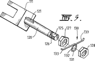
この場合、マウント111にはシャフト120が設けられ、シャフトはその内端にキー121が設けられ、キー121はシャフト内に入れられてもよいし、シャフト形成の一部として形成されてもよい。
【0024】
フットレスト本体140の孔122には凹所123が設けられ、その凹所123はキー121と略同じ長さと、シャフトに対して本体の必要な動きを提供するのに充分ではあるが、キーが凹所123の両端に当たった時にはストップとして作用する、角度のある長さとを有する。
【0025】
その外端において、シャフトはスレッド126を有する平らな部分125を有し、この配置では、ロックナット127がスレッド126の上を通過することができ、また後述するように、シャフト上の平ら部125の上を通るようになっている中央孔132を有する本体131を有するばね130を有する、従ってばねの中央が回転するのが防止され、またそこから伸びる一対のアーム133を有する。
【0026】
フットレスト本体140を配置した後、ばね130を適所に置き、更にナット128をスレッド126の上に締め付ける。
【0027】
2本のアーム133は、図7に見られるように、変形した外端を有することができ、それはレスト本体の前方・後方端のまわりに、またはその下に位置することができる。
【0028】
図7から解るように、ばねは各回転方向で、ばねのばね板の一方が変形して、概して本体140を中央位置へともたらそうとするバイアス作用があるので、本体の回転に対する抵抗力を提供する。
【0029】
前述のように、凹所123とキー121がシャフトに対する本体の回転運動におけるリミットとして作用する。
【0030】
操作に際して、両実施形態は同じような方法で効果的に作用する。いずれの場合にも、レスト本体は通常中央の通常位置に保持され、まっすぐ乗った場合、運転者の足がこの位置でレストの上にある。
【0031】
しかし、乗車中に、または極度のコーナリングに際して障害物に近づいた時の体、あるいはギアチェンジまたはフットブレーキを操作するために使用されるときの足等、運転者が体または足の位置を動かす必要がある場合、運転者のブーツの底が姿勢制御中にレスト本体全体と効果的に接触したままであるように、レスト本体が回転することができる。つまり、運転者に関する限り、安定性を達成するのに必要である場合、レスト上のグリップが失われない。
【0032】
姿勢制御が完了すると同時に、その中央位置に戻ろうとする体の偏りの下での動きがあり、中央位置が達成されるであろう。
【0033】
デザインによって、運転者の足からの直接的な圧力によって前方及び後方へと旋回するであろう、便利な耐久性のある自動二輪車用フットレストを提供する本発明によって、従来の自動二輪車用フットレストに関連する問題が克服されるか、または最小にされるであろう。この旋回動作のために、フットレストの全表面が運転者の足の動きに追随することができる。これはグリップポイントの最大限可能な接触が達成されることを保証する。
【0034】
更にこのフットレストの旋回動作は、より制御された淀みない方法で運転者が乗車位置を変更できる一方、より大きな足元の確かさを維持することができるようにする。
【0035】
またこのフットレストの旋回動作は、足踏み制御、つまりリアブレーキとギアシフトの使用に際して運転者を補助する。
【0036】
更に、自動二輪車が不安定な状態に遭遇し、自動二輪車の前部と後部を交互に上下させる場合、フットレストの旋回動作は、自動二輪車がフットレストの軸上の運転者の下で揺動できるようにし、フットレストの全表面が再び運転者の足の下側と絶えず接触したままであるようにするので、最大限可能なグリップと荷重分布を達成する。
【0037】
ここでは発明の2つの特定の実施形態について説明してきたが、ここで使用した機械的配置は抜てきの1つであって、制限的なものではなく、機械的配置や、レスト本体のサイズや突起の形成は、発明の範囲から逸脱することなく変化させることができる。
【図面の簡単な説明】
【0038】
【図1】図1は自動二輪車のフレームの一部に添付されたフットレストの第1実施形態を示す斜視図である。
【図2】図2は図1のフットレストの分解図である。
【図3】図3は図1及び図2のフットレストの側面図である。
【図4】図4は図2の線4−4に沿った断面図である。
【図5】図5はフットレストの第2形態の斜視図である。
【図6】図6はその実施形態の一部分解図である。
【図7】図7は図5の線7−7に沿った断面図である。
【図8】図8は図5の線8−8に沿った断面図である。【Technical field】
[0001]
The present invention relates to a motorcycle, and more particularly, to an improvement in a motorcycle footrest. In this specification, when referring to a motorcycle, it includes two and three-wheeled motorcycles, and also includes all four-wheeled vehicles that can be ridden in the same manner as motorcycles.
[Background]
[0002]
As is known, most motorcycle assemblies include a frame having a seat over which the driver sits. A pair of footrests are supported on both sides of the lower end of the frame for placing a foot when the driver gets on. Often, a control device for operating certain parts of the motorcycle, such as rear wheel brakes or gear shifts, is placed in proximity to the footrest. This allows the control to be activated with the foot when the driver desires.
[0003]
It is common for the appearance of a motorcycle footrest to change depending on the intended application. Overall its basic design is the same, that is, footrest provides projections inert in place to support the driver's feet.
[0004]
Conventional motorcycle footrest designs have inherent disadvantages.
[0005]
For example, a motorcycle footrest made for off-road use is created with an extreme tooth profile design to make it easier for the driver's foot to grip the footrest under all conditions. Often, however, the grip points of the footrest cannot remain in constant contact with the maximum possible surface area of the driver's foot. For example, when the vehicle encounters an unstable condition and / or the driver moves to a body position where the angle of the foot, in particular the angle of the sole of the foot, is smaller or larger than the angle of the footrest. is there. When this happens, the foot part moves away from the footrest. This reduction in grip also occurs when the driver's foot has to move to manipulate the foot control.
[0006]
In addition, current manufacturing designs recognize the need for wider footrests in some applications to help distribute the load placed on the driver's foot during high impact situations. However, if the foot angle is not correct with respect to the surface angle of the footrest, the load cannot be uniformly absorbed and distributed over the entire surface of the footrest, which can result in loss of scaffolding and loss of control.
[0007]
The main object of the present invention is to provide an improved footrest for a motorcycle.
[0008]
Yet another object of the present invention is to provide a motorcycle footrest that improves the reliability and control of the driver's feet.
DISCLOSURE OF THE INVENTION
[Problems to be solved by the invention]
[0009]
The invention, in its broadest aspect, includes a motorcycle footrest, the body portion having an upper surface adapted to receive a driver's foot and having a hole extending through at least a substantial portion of its length; A mount coupled to the frame of the motorcycle and a shaft extending outwardly from the mount and receiving a body portion thereon so that the body can rotate about the axis of the shaft.
[0010]
The present invention provides a motorcycle footrest that allows a motorcycle driver to obtain a desired body position in a light and controlled manner. This is most desirable. This is because the position of the driver's body determines the center of gravity and weight bias over a region of the motorcycle that fundamentally affects its handling and grip. This special assistance helps the driver save energy, reduce fatigue and thereby maintain a high level of mental concentration.
[0011]
In order to facilitate understanding of the present invention, two embodiments of the invention will be described by way of example and in conjunction with the accompanying drawings.
[0012]
The embodiment shown in FIGS. 1-4 shows a
[0013]
As shown in FIG. 2, the mount can have two
[0014]
If necessary, the mount may be held against the motorcycle by bolts or the like. Extending from the mount is a
[0015]
The
[0016]
The
[0017]
These shapes will depend on how the motorcycle is used. If the motorcycle is basically used on roads and in benign conditions, the protrusions need only be sufficient to allow excellent grip under these circumstances. If the motorcycle is to be used off-road and in competition, a
[0018]
If the motorcycle is used more leisurely, a
[0019]
When assembling, the
[0020]
The needle bearing 25 can be mounted in or adjacent to both ends of the
[0021]
The
[0022]
The embodiments of FIGS. 5-8 are basically similar in form to the first embodiment, but differ in certain aspects.
[0023]
In this case, the
[0024]
The
[0025]
At its outer end, the shaft has a
[0026]
After placing the
[0027]
The two
[0028]
As can be seen from FIG. 7, the spring has a biasing action that, in each direction of rotation, causes one of the spring leaf plates to deform, generally bringing the
[0029]
As described above, the
[0030]
In operation, both embodiments work effectively in a similar manner. In either case, the rest body is usually held in the normal position in the center, and when riding straight, the driver's feet are above the rest in this position.
[0031]
However, the driver must move the position of the body or foot, such as when riding, or when approaching an obstacle during extreme cornering, or when used to operate a gear change or foot brake If there is, the rest body can be rotated so that the bottom of the driver's boot remains effectively in contact with the entire rest body during posture control. That is, as far as the driver is concerned, the grip on the rest is not lost when necessary to achieve stability.
[0032]
At the same time that posture control is complete, there will be movement under the bias of the body trying to return to its central position and the central position will be achieved.
[0033]
Related to the traditional motorcycle footrest by the present invention, which provides a convenient and durable motorcycle footrest that will swing forward and backward by direct pressure from the driver's foot by design Problems to be overcome will be overcome or minimized. Because of this turning motion, the entire surface of the footrest can follow the movement of the driver's foot. This ensures that the maximum possible contact of the grip points is achieved.
[0034]
Furthermore, the swivel movement of the footrest allows the driver to change the boarding position in a more controlled and sane manner while maintaining greater foot certainty.
[0035]
Further, the turning motion of the footrest assists the driver in the stepping control, that is, the use of the rear brake and the gear shift.
[0036]
In addition, if the motorcycle encounters an unstable condition and the front and rear of the motorcycle are alternately raised and lowered, the turning movement of the footrest will allow the motorcycle to swing under the driver on the footrest axis. And the entire surface of the footrest remains in constant contact with the underside of the driver's foot again, achieving the maximum possible grip and load distribution.
[0037]
Although two specific embodiments of the invention have been described here, the mechanical arrangement used here is one of the extractions and is not restrictive; it is not limited to mechanical arrangements, rest body sizes and protrusions. The formation of can be varied without departing from the scope of the invention.
[Brief description of the drawings]
[0038]
FIG. 1 is a perspective view showing a first embodiment of a footrest attached to a part of a frame of a motorcycle.
FIG. 2 is an exploded view of the footrest of FIG.
FIG. 3 is a side view of the footrest of FIGS. 1 and 2;
FIG. 4 is a cross-sectional view taken along line 4-4 of FIG.
FIG. 5 is a perspective view of a second form of the footrest.
FIG. 6 is a partially exploded view of the embodiment.
7 is a cross-sectional view taken along line 7-7 of FIG.
FIG. 8 is a cross-sectional view taken along line 8-8 of FIG.
Claims (9)
シャフトに対する本体部分の左右の回転角が制限される手段が設けられ、
本体部分が中央位置から左または右に回転させられた時に、本体部分を回転させて中央位置へと移動させる付勢手段を有することを特徴とするフットレスト。A motorcycle footrest having a body portion whose top surface is adapted to receive a driver's foot and having a hole extending through at least a substantial portion of its length, and a mount coupled to the motorcycle frame And a shaft extending outwardly from the mount and receiving a body portion thereon, whereby the body portion can rotate left and right about the shaft axis,
Means for limiting the left and right rotation angles of the body portion relative to the shaft;
A footrest comprising biasing means for rotating the main body portion to the central position when the main body portion is rotated left or right from the central position.
Applications Claiming Priority (3)
| Application Number | Priority Date | Filing Date | Title |
|---|---|---|---|
| AU6048 | 1998-09-21 | ||
| AUPP6048A AUPP604898A0 (en) | 1998-09-21 | 1998-09-21 | Pivoting motorcycle footpeg |
| PCT/AU1999/000796 WO2000017038A1 (en) | 1998-09-21 | 1999-09-21 | Motorcycle pivoting foot pegs |
Publications (3)
| Publication Number | Publication Date |
|---|---|
| JP2002526322A JP2002526322A (en) | 2002-08-20 |
| JP2002526322A5 JP2002526322A5 (en) | 2006-11-16 |
| JP4585120B2 true JP4585120B2 (en) | 2010-11-24 |
Family
ID=3810265
Family Applications (1)
| Application Number | Title | Priority Date | Filing Date |
|---|---|---|---|
| JP2000573965A Expired - Fee Related JP4585120B2 (en) | 1998-09-21 | 1999-09-21 | Pivoting footrest for motorcycle |
Country Status (8)
| Country | Link |
|---|---|
| US (1) | US6663129B1 (en) |
| EP (1) | EP1115608B1 (en) |
| JP (1) | JP4585120B2 (en) |
| AT (1) | ATE314246T1 (en) |
| AU (1) | AUPP604898A0 (en) |
| DE (1) | DE69929217T2 (en) |
| ES (1) | ES2253914T3 (en) |
| WO (1) | WO2000017038A1 (en) |
Families Citing this family (36)
| Publication number | Priority date | Publication date | Assignee | Title |
|---|---|---|---|---|
| US7316302B2 (en) * | 2001-12-14 | 2008-01-08 | Efraeyim Hogesta | Motorcycle disk-brake lock |
| EP1458608B1 (en) * | 2001-12-14 | 2006-06-07 | Efraeyim Hogesta | Disk-brake lock for a motorcycle |
| US6863292B1 (en) * | 2002-03-29 | 2005-03-08 | Roller Peg, Inc. | Bicycle or skateboard peg with independently rotatable surface |
| US7025368B2 (en) * | 2003-02-21 | 2006-04-11 | Barnes Timothy E | Protective cage for motorcycle engine |
| US7111375B2 (en) * | 2003-04-10 | 2006-09-26 | Harley-Davidson Motor Company Group, Inc. | Footpeg for a motorcycle |
| US6893038B2 (en) * | 2003-07-16 | 2005-05-17 | Kuryakyn Holdings, Inc. | Motorcycle foot peg with folding heel rest |
| CA2452444A1 (en) * | 2003-12-04 | 2005-06-04 | Soucy International Inc. | Floor board |
| US7278336B2 (en) * | 2004-03-17 | 2007-10-09 | Clark John A | Adjustable shift lever assembly |
| US20050241435A1 (en) * | 2004-04-30 | 2005-11-03 | Colano Richard V | Fork-like, direct link to shifter |
| US7163225B2 (en) * | 2005-02-16 | 2007-01-16 | Michael Alan Honea | Foot peg |
| US7458596B1 (en) | 2005-06-30 | 2008-12-02 | James Serna | Bicycle peg assembly |
| US20070057484A1 (en) * | 2005-07-18 | 2007-03-15 | Greg Gilman | In-folding motorcycle foot rests |
| US7431118B1 (en) | 2005-12-09 | 2008-10-07 | Hogg Gordon S | Motorcycle floorboard apparatus |
| US20080047389A1 (en) * | 2006-08-24 | 2008-02-28 | Harley-Davidson Motor Company Group, Inc. | Foot peg assembly for a motorcycle |
| US20080179859A1 (en) * | 2007-01-25 | 2008-07-31 | Boehmke Steven L | Motorcycle foot peg and boot cleat assembly |
| US20090008170A1 (en) * | 2007-07-03 | 2009-01-08 | Claussen Travis W | Multi-plane motorcycle foot peg |
| US20100242554A1 (en) * | 2007-10-30 | 2010-09-30 | Efraeyim Hogesta | Locking method, system and kit for a motorcycle |
| US8087321B2 (en) * | 2007-12-28 | 2012-01-03 | Kyle Hollingsworth | Removable shoe guard |
| US7914032B2 (en) * | 2008-06-04 | 2011-03-29 | Kick Rest, Llc | Motorcycle leg rest |
| US20100127474A1 (en) * | 2008-11-21 | 2010-05-27 | John Jans | Pivoting motorcycle footpeg |
| CN101531226B (en) * | 2009-04-10 | 2011-07-06 | 重庆隆鑫机车有限公司 | Motorcycle pedal |
| US8444165B2 (en) * | 2010-03-15 | 2013-05-21 | Jessica Renee Houser | Guard bar and tunable footpeg system for all-terrain vehicles |
| US20110247452A1 (en) * | 2010-04-12 | 2011-10-13 | Shuji Kawai | Interchangeable bicycle pedal system |
| DE102010017607B4 (en) | 2010-06-25 | 2012-03-08 | Stephanie Kopf | footrest |
| LU91742B1 (en) | 2010-10-04 | 2012-04-05 | Gilles Tooling Gmbh | Footrest device with rotating footrest, double-sided footrest and footrest with damping |
| EP2517621A1 (en) | 2011-04-29 | 2012-10-31 | Nederlandse Organisatie voor toegepast -natuurwetenschappelijk onderzoek TNO | A radar apparatus for detecting multiple life-signs of a subject, a method and a computer program product |
| US11080765B2 (en) | 2013-03-14 | 2021-08-03 | Igor Gershteyn | Method and system for data structure creation, organization and searching using basic atomic units of information |
| US9132876B2 (en) * | 2013-11-14 | 2015-09-15 | Craig M. Grose | Omnidirectional vibration isolating foot peg |
| US9290225B2 (en) * | 2013-11-20 | 2016-03-22 | Igor Gershteyn | Motorcycle foot anchor |
| JP6232669B2 (en) * | 2014-01-15 | 2017-11-22 | 本田技研工業株式会社 | Step structure of saddle-ride type vehicle |
| US9352795B2 (en) * | 2014-01-31 | 2016-05-31 | Kuryakyn Holdings, LLC | Motorcycle footrest mount |
| JP6244287B2 (en) * | 2014-09-30 | 2017-12-06 | 本田技研工業株式会社 | Vehicle with steps |
| US9540066B1 (en) | 2016-01-06 | 2017-01-10 | CRG Racing, LLC | Foot peg assembly for A saddle-type vehicle |
| US11845507B2 (en) * | 2016-10-11 | 2023-12-19 | Charlie Hon | Motorcycle foot peg assembly with angled teeth |
| WO2019092589A2 (en) * | 2017-11-07 | 2019-05-16 | Efraeyim Hogesta | Universal dual-purpose lock for motorcycle |
| DE202019000782U1 (en) * | 2019-02-18 | 2019-03-25 | Fritz Klein | Shift pedal and shift lever |
Family Cites Families (20)
| Publication number | Priority date | Publication date | Assignee | Title |
|---|---|---|---|---|
| US499549A (en) * | 1893-06-13 | John h | ||
| US374287A (en) * | 1887-12-06 | Bicycle-step | ||
| GB166414A (en) * | 1920-05-25 | 1921-07-21 | Beasley Smith | Improvements in resilient footboards for use on motor cycles and the like |
| GB223326A (en) * | 1923-07-25 | 1924-10-23 | Robert Smith Cundle | New or improved foot-rest appliance for use in connection with motor cycles or like vehicles |
| GB276167A (en) * | 1926-09-28 | 1927-08-25 | Franke Aktien Ges Geb | Improvements relating to foot rests for motor cycles and other like vehicles |
| US4458910A (en) | 1982-09-29 | 1984-07-10 | Stillwagon Steven R | Foot retainer |
| JPS6018471A (en) * | 1983-07-10 | 1985-01-30 | 池田 時広 | Step for car |
| US4546993A (en) * | 1983-10-13 | 1985-10-15 | Walker George R | Adjustable motorcycle passenger floorboard |
| JPH0127513Y2 (en) * | 1984-09-28 | 1989-08-17 | ||
| JPS626189U (en) * | 1985-06-28 | 1987-01-14 | ||
| JPS6391989U (en) * | 1986-12-06 | 1988-06-14 | ||
| JPH03248982A (en) * | 1990-02-28 | 1991-11-06 | Suzuki Motor Corp | Foot rest bracket for motorcycle |
| US5482307A (en) * | 1994-06-07 | 1996-01-09 | Lin; Frank | Footrest assembly for motorcycle |
| US5454580A (en) * | 1994-06-07 | 1995-10-03 | Lin; Frank | Footrest for motorcycle |
| US5638723A (en) * | 1995-08-14 | 1997-06-17 | Lin; Frank | Motorcycle step |
| US6003407A (en) * | 1996-07-22 | 1999-12-21 | Cavalier; Gregg S. | Sealing device for motorcycle toe shift mechanism |
| US5826900A (en) * | 1996-09-10 | 1998-10-27 | Steele; Robert | Vehicle foot peg |
| JPH10119857A (en) * | 1996-10-22 | 1998-05-12 | Suzuki Motor Corp | Foot pedal for motorcycle and mounting device for footrest |
| US6070897A (en) * | 1998-04-21 | 2000-06-06 | Hsieh; Te-Tsai | Foot peg of bicycle |
| US6161859A (en) * | 1998-12-21 | 2000-12-19 | Cheng; Chun Ling | Foot pegs for motorcycles |
-
1998
- 1998-09-21 AU AUPP6048A patent/AUPP604898A0/en not_active Abandoned
-
1999
- 1999-09-21 JP JP2000573965A patent/JP4585120B2/en not_active Expired - Fee Related
- 1999-09-21 DE DE69929217T patent/DE69929217T2/en not_active Expired - Lifetime
- 1999-09-21 ES ES99947121T patent/ES2253914T3/en not_active Expired - Lifetime
- 1999-09-21 EP EP99947121A patent/EP1115608B1/en not_active Expired - Lifetime
- 1999-09-21 WO PCT/AU1999/000796 patent/WO2000017038A1/en active IP Right Grant
- 1999-09-21 AT AT99947121T patent/ATE314246T1/en active
- 1999-09-21 US US09/787,687 patent/US6663129B1/en not_active Expired - Lifetime
Also Published As
| Publication number | Publication date |
|---|---|
| EP1115608A4 (en) | 2003-03-05 |
| EP1115608A1 (en) | 2001-07-18 |
| US6663129B1 (en) | 2003-12-16 |
| EP1115608B1 (en) | 2005-12-28 |
| DE69929217T2 (en) | 2006-08-24 |
| JP2002526322A (en) | 2002-08-20 |
| DE69929217D1 (en) | 2006-02-02 |
| WO2000017038A1 (en) | 2000-03-30 |
| AUPP604898A0 (en) | 1998-10-15 |
| ATE314246T1 (en) | 2006-01-15 |
| ES2253914T3 (en) | 2006-06-01 |
Similar Documents
| Publication | Publication Date | Title |
|---|---|---|
| JP4585120B2 (en) | Pivoting footrest for motorcycle | |
| US7637338B2 (en) | All-terrain vehicle | |
| US4909537A (en) | Universal vehicle for pedaling or the like | |
| CA1067533A (en) | Lock bar for cambering vehicle | |
| US20070152422A1 (en) | Pivotable device for bicycles or tricycles | |
| JP3184172B2 (en) | Bicycle pedals | |
| US5501477A (en) | Bicycle | |
| US20100059956A1 (en) | Brake assembly and scooters and skateboards including the same | |
| US6170841B1 (en) | Steering system for straddle type four-wheeled all-terrain vehicle | |
| US9278723B2 (en) | Recumbent vehicle | |
| US20180243638A1 (en) | Multi-Pivoting Steering Mechanism | |
| US6648357B2 (en) | Vehicle kickstands and foot pegs | |
| CA2396733A1 (en) | Ride-on vehicle with direction responsive mechanism | |
| KR101943296B1 (en) | Wheelchair connecting mount with rollover prevention function in direction change | |
| JP7112148B1 (en) | Vehicle with swing mechanism | |
| AU755186C (en) | Motorcycle pivoting foot pegs | |
| JP2531798B2 (en) | Front two-wheeled tricycle | |
| US5540308A (en) | Parking lock for vehicle | |
| JP2010132185A (en) | Snowmobile | |
| CA2411302A1 (en) | Steering post for a recreational vehicle | |
| US20020135146A1 (en) | Inclination prevention structure of child wheeled vehicle | |
| US4410195A (en) | Bicycle with improved safety | |
| CN211167234U (en) | Scooter | |
| JP7042535B1 (en) | Vehicle with swing mechanism | |
| JP2001114167A (en) | Fitting structure of footrest for motorcycle |
Legal Events
| Date | Code | Title | Description |
|---|---|---|---|
| A521 | Request for written amendment filed |
Free format text: JAPANESE INTERMEDIATE CODE: A523 Effective date: 20060913 |
|
| A621 | Written request for application examination |
Free format text: JAPANESE INTERMEDIATE CODE: A621 Effective date: 20060913 |
|
| A977 | Report on retrieval |
Free format text: JAPANESE INTERMEDIATE CODE: A971007 Effective date: 20081211 |
|
| A131 | Notification of reasons for refusal |
Free format text: JAPANESE INTERMEDIATE CODE: A131 Effective date: 20081216 |
|
| A601 | Written request for extension of time |
Free format text: JAPANESE INTERMEDIATE CODE: A601 Effective date: 20090316 |
|
| A602 | Written permission of extension of time |
Free format text: JAPANESE INTERMEDIATE CODE: A602 Effective date: 20090330 |
|
| A521 | Request for written amendment filed |
Free format text: JAPANESE INTERMEDIATE CODE: A523 Effective date: 20090415 |
|
| A131 | Notification of reasons for refusal |
Free format text: JAPANESE INTERMEDIATE CODE: A131 Effective date: 20091027 |
|
| A601 | Written request for extension of time |
Free format text: JAPANESE INTERMEDIATE CODE: A601 Effective date: 20100126 |
|
| A602 | Written permission of extension of time |
Free format text: JAPANESE INTERMEDIATE CODE: A602 Effective date: 20100202 |
|
| A601 | Written request for extension of time |
Free format text: JAPANESE INTERMEDIATE CODE: A601 Effective date: 20100226 |
|
| A521 | Request for written amendment filed |
Free format text: JAPANESE INTERMEDIATE CODE: A523 Effective date: 20100303 |
|
| A602 | Written permission of extension of time |
Free format text: JAPANESE INTERMEDIATE CODE: A602 Effective date: 20100310 |
|
| TRDD | Decision of grant or rejection written | ||
| A01 | Written decision to grant a patent or to grant a registration (utility model) |
Free format text: JAPANESE INTERMEDIATE CODE: A01 Effective date: 20100824 |
|
| A01 | Written decision to grant a patent or to grant a registration (utility model) |
Free format text: JAPANESE INTERMEDIATE CODE: A01 |
|
| A61 | First payment of annual fees (during grant procedure) |
Free format text: JAPANESE INTERMEDIATE CODE: A61 Effective date: 20100903 |
|
| R150 | Certificate of patent or registration of utility model |
Free format text: JAPANESE INTERMEDIATE CODE: R150 |
|
| FPAY | Renewal fee payment (event date is renewal date of database) |
Free format text: PAYMENT UNTIL: 20130910 Year of fee payment: 3 |
|
| R250 | Receipt of annual fees |
Free format text: JAPANESE INTERMEDIATE CODE: R250 |
|
| R250 | Receipt of annual fees |
Free format text: JAPANESE INTERMEDIATE CODE: R250 |
|
| R250 | Receipt of annual fees |
Free format text: JAPANESE INTERMEDIATE CODE: R250 |
|
| LAPS | Cancellation because of no payment of annual fees |