JP4582144B2 - HEAT CONDUCTIVE SHEET, ITS MANUFACTURING METHOD, AND POWER MODULE USING HEAT CONDUCTIVE SHEET - Google Patents
HEAT CONDUCTIVE SHEET, ITS MANUFACTURING METHOD, AND POWER MODULE USING HEAT CONDUCTIVE SHEET Download PDFInfo
- Publication number
- JP4582144B2 JP4582144B2 JP2007525482A JP2007525482A JP4582144B2 JP 4582144 B2 JP4582144 B2 JP 4582144B2 JP 2007525482 A JP2007525482 A JP 2007525482A JP 2007525482 A JP2007525482 A JP 2007525482A JP 4582144 B2 JP4582144 B2 JP 4582144B2
- Authority
- JP
- Japan
- Prior art keywords
- thin
- conductive sheet
- heat conductive
- sheet
- pieces
- Prior art date
- Legal status (The legal status is an assumption and is not a legal conclusion. Google has not performed a legal analysis and makes no representation as to the accuracy of the status listed.)
- Expired - Fee Related
Links
Images


Classifications
-
- H—ELECTRICITY
- H01—ELECTRIC ELEMENTS
- H01L—SEMICONDUCTOR DEVICES NOT COVERED BY CLASS H10
- H01L23/00—Details of semiconductor or other solid state devices
- H01L23/34—Arrangements for cooling, heating, ventilating or temperature compensation ; Temperature sensing arrangements
- H01L23/36—Selection of materials, or shaping, to facilitate cooling or heating, e.g. heatsinks
- H01L23/373—Cooling facilitated by selection of materials for the device or materials for thermal expansion adaptation, e.g. carbon
- H01L23/3733—Cooling facilitated by selection of materials for the device or materials for thermal expansion adaptation, e.g. carbon having a heterogeneous or anisotropic structure, e.g. powder or fibres in a matrix, wire mesh, porous structures
-
- H—ELECTRICITY
- H01—ELECTRIC ELEMENTS
- H01L—SEMICONDUCTOR DEVICES NOT COVERED BY CLASS H10
- H01L23/00—Details of semiconductor or other solid state devices
- H01L23/34—Arrangements for cooling, heating, ventilating or temperature compensation ; Temperature sensing arrangements
- H01L23/36—Selection of materials, or shaping, to facilitate cooling or heating, e.g. heatsinks
- H01L23/367—Cooling facilitated by shape of device
- H01L23/3677—Wire-like or pin-like cooling fins or heat sinks
-
- H—ELECTRICITY
- H01—ELECTRIC ELEMENTS
- H01L—SEMICONDUCTOR DEVICES NOT COVERED BY CLASS H10
- H01L2224/00—Indexing scheme for arrangements for connecting or disconnecting semiconductor or solid-state bodies and methods related thereto as covered by H01L24/00
- H01L2224/01—Means for bonding being attached to, or being formed on, the surface to be connected, e.g. chip-to-package, die-attach, "first-level" interconnects; Manufacturing methods related thereto
- H01L2224/42—Wire connectors; Manufacturing methods related thereto
- H01L2224/47—Structure, shape, material or disposition of the wire connectors after the connecting process
- H01L2224/48—Structure, shape, material or disposition of the wire connectors after the connecting process of an individual wire connector
- H01L2224/4805—Shape
- H01L2224/4809—Loop shape
- H01L2224/48091—Arched
-
- H—ELECTRICITY
- H01—ELECTRIC ELEMENTS
- H01L—SEMICONDUCTOR DEVICES NOT COVERED BY CLASS H10
- H01L2224/00—Indexing scheme for arrangements for connecting or disconnecting semiconductor or solid-state bodies and methods related thereto as covered by H01L24/00
- H01L2224/01—Means for bonding being attached to, or being formed on, the surface to be connected, e.g. chip-to-package, die-attach, "first-level" interconnects; Manufacturing methods related thereto
- H01L2224/42—Wire connectors; Manufacturing methods related thereto
- H01L2224/47—Structure, shape, material or disposition of the wire connectors after the connecting process
- H01L2224/48—Structure, shape, material or disposition of the wire connectors after the connecting process of an individual wire connector
- H01L2224/481—Disposition
- H01L2224/48135—Connecting between different semiconductor or solid-state bodies, i.e. chip-to-chip
- H01L2224/48137—Connecting between different semiconductor or solid-state bodies, i.e. chip-to-chip the bodies being arranged next to each other, e.g. on a common substrate
-
- H—ELECTRICITY
- H01—ELECTRIC ELEMENTS
- H01L—SEMICONDUCTOR DEVICES NOT COVERED BY CLASS H10
- H01L2224/00—Indexing scheme for arrangements for connecting or disconnecting semiconductor or solid-state bodies and methods related thereto as covered by H01L24/00
- H01L2224/01—Means for bonding being attached to, or being formed on, the surface to be connected, e.g. chip-to-package, die-attach, "first-level" interconnects; Manufacturing methods related thereto
- H01L2224/42—Wire connectors; Manufacturing methods related thereto
- H01L2224/47—Structure, shape, material or disposition of the wire connectors after the connecting process
- H01L2224/48—Structure, shape, material or disposition of the wire connectors after the connecting process of an individual wire connector
- H01L2224/481—Disposition
- H01L2224/48151—Connecting between a semiconductor or solid-state body and an item not being a semiconductor or solid-state body, e.g. chip-to-substrate, chip-to-passive
- H01L2224/48221—Connecting between a semiconductor or solid-state body and an item not being a semiconductor or solid-state body, e.g. chip-to-substrate, chip-to-passive the body and the item being stacked
- H01L2224/48245—Connecting between a semiconductor or solid-state body and an item not being a semiconductor or solid-state body, e.g. chip-to-substrate, chip-to-passive the body and the item being stacked the item being metallic
- H01L2224/48247—Connecting between a semiconductor or solid-state body and an item not being a semiconductor or solid-state body, e.g. chip-to-substrate, chip-to-passive the body and the item being stacked the item being metallic connecting the wire to a bond pad of the item
-
- H—ELECTRICITY
- H01—ELECTRIC ELEMENTS
- H01L—SEMICONDUCTOR DEVICES NOT COVERED BY CLASS H10
- H01L2924/00—Indexing scheme for arrangements or methods for connecting or disconnecting semiconductor or solid-state bodies as covered by H01L24/00
- H01L2924/15—Details of package parts other than the semiconductor or other solid state devices to be connected
- H01L2924/181—Encapsulation
Description
本発明は、例えばパワー半導体素子等の発熱体からの熱を放出する熱伝導シートおよびその製造方法、並びに熱伝導シートを用いたパワーモジュールに関するものである。 The present invention relates to a heat conductive sheet that releases heat from a heating element such as a power semiconductor element, a manufacturing method thereof, and a power module using the heat conductive sheet.
電力回路が実装されたリードフレームの、上記電力回路が実装された面の反対面に、Al2O3、AlNまたはBeO等、絶縁性および熱伝導性に優れた物質からなる絶縁体(セラミックス板)を熱伝導シートとして接着したものがある(例えば特許文献1参照)。An insulator (ceramics plate) made of a material having excellent insulation and thermal conductivity, such as Al 2 O 3 , AlN or BeO, on the opposite side of the surface on which the power circuit is mounted of the lead frame on which the power circuit is mounted ) As a heat conductive sheet (see, for example, Patent Document 1).
従来のセラミックス板からなる熱伝導シートは、接着面形状に追随するのが困難で、例えばヒートスプレッダまたはリードフレームなどに接着した場合、ヒートスプレッダまたはリードフレームからの応力を受けやすい。
そこで、セラミックス板を薄くすると強度が劣るため、上記応力によるクラックが発生し易くなり、セラミックス板を厚くすると上記クラックは防止できるが熱伝導シートの熱伝導性が低下するという課題があった。A conventional heat conductive sheet made of a ceramic plate is difficult to follow the shape of an adhesive surface, and is easily subjected to stress from the heat spreader or the lead frame, for example, when bonded to a heat spreader or a lead frame.
Therefore, when the ceramic plate is made thin, the strength is inferior, so that cracks due to the stress tend to occur. When the ceramic plate is made thick, the crack can be prevented but the thermal conductivity of the heat conductive sheet is lowered.
本発明は、かかる課題を解決するためになされたものであり、熱伝導性に優れると共に、熱伝導シート内の、セラミックスに代表される熱伝導性を有する材料におけるクラックの発生が防止された熱伝導シートを得ることを目的とする。また、製造方法が容易でコスト面でも有利である熱伝導シートの製造方法を得ることを目的とする。また、高容量化が可能なパワーモジュールを得ることを目的とする。 The present invention has been made to solve such a problem, and is excellent in thermal conductivity, and is a heat in which generation of cracks in a material having thermal conductivity typified by ceramics in a thermal conductive sheet is prevented. The purpose is to obtain a conductive sheet. Another object of the present invention is to obtain a method for producing a heat conductive sheet that is easy in production and advantageous in terms of cost. It is another object of the present invention to obtain a power module capable of increasing the capacity.
本発明に係る第1の熱伝導シートは、互いに隣接して設けられ、熱伝導性を有する複数の薄体片と、複数の上記薄体片の側面の間に介在し、上記側面間を接着してシートとする樹脂組成物とを備え、複数の上記薄体片の側面間の間隔が、0.1mm以上、3mm以下であり、被熱伝導体の搭載領域における上記薄体片の間隔が、上記被熱伝導体の非搭載領域における上記薄体片の間隔より狭いことを特徴とするものである。また、本発明に係る第2の熱伝導シートは、互いに隣接して設けられ、熱伝導性を有する複数の薄体片と、複数の上記薄体片の側面の間に介在し、上記側面間を接着してシートとする樹脂組成物とを備えた熱伝導シートであって、上記薄体片の面方向の大きさが3mm角以上、25mm角以下であり、被熱伝導体の搭載領域における上記薄体片の面方向の大きさが、上記被熱伝導体の非搭載領域における上記薄体片の大きさより大であることを特徴とするものである。 The first thermal conductive sheet according to the present invention is provided adjacent to each other, and is interposed between a plurality of thin body pieces having thermal conductivity and the side surfaces of the plurality of thin body pieces, and bonds the side surfaces to each other. And the interval between the side surfaces of the plurality of thin pieces is 0.1 mm or more and 3 mm or less, and the distance between the thin pieces in the mounting region of the thermal conductor is The space between the thin pieces in the non-mounting region of the heat conductor is narrower. Further, the second heat conductive sheet according to the present invention is provided adjacent to each other, and is interposed between the plurality of thin pieces having heat conductivity and the side surfaces of the plurality of thin pieces, and between the side faces. And a resin composition that forms a sheet by adhering to each other, wherein the size of the thin piece in the surface direction is not less than 3 mm square and not more than 25 mm square, and in the mounting area of the heat conductor A size of the thin piece in a surface direction is larger than a size of the thin piece in a non-mounting region of the heat conductor.
本発明によれば、熱伝導性を有する複数の薄体片が互いに隣接して設けられているので、熱伝導性に優れると共に熱伝導シートにおけるクラックが防止されるという効果がある。 According to the present invention, since the plurality of thin pieces having thermal conductivity are provided adjacent to each other, the thermal conductivity is excellent and cracks in the thermal conductive sheet are prevented.
1 熱伝導シート、2 樹脂組成物、20 樹脂層、21 表面樹脂層、3 薄体、31 薄体片、32 側面(分断面)、33 溝、34 表面、5 保持シート(粘着シート)、6 発熱体(被熱伝導体)、7 パワーモジュール。
DESCRIPTION OF
実施の形態1.
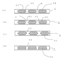
図1は、本発明の実施の形態1における、熱伝導シートの概略構成を示す上面図と断面図であり、(a)は本実施の形態の熱伝導シート1の表面に設けられた表面樹脂層21を透視した上面図、(b)は(a)のa−a線断面における、熱伝導シート1の断面図である。
図1に示すように、本実施の形態の熱伝導シート1は、熱伝導性を有する複数の薄体片31が面方向に互いに隣接し、この薄体片31の側面32の間に樹脂組成物2が介在し、上記側面32が樹脂組成物2により接着されてシートとなったもので、セラミックス板に代表される熱伝導材料を一枚で用いるのではなく、上記熱伝導材料を複数の薄体片31として用いることにより、例えばヒートスプレッダまたはリードフレームからの応力を緩和することが可能となり、クラックが防止できる。なお、本実施の形態の熱伝導シート1には、上記樹脂組成物2が薄体片31の表面34にも連続して設けられて、表面樹脂層21を形成している。
1A and 1B are a top view and a cross-sectional view showing a schematic configuration of a heat conductive sheet in
As shown in FIG. 1, in the heat
表1は、本実施の形態の熱伝導シート1における薄体片31の面方向の大きさおよび間隔と、熱伝導シート1の特性を示す。
Table 1 shows the size and interval in the surface direction of the

つまり、本実施の形態においては、樹脂組成物2がエポキシ樹脂であり、薄体片31が0.63mm厚のAlN(窒化アルミ)のセラミックス板からなり、表1に示すように面方向の大きさが1mm角〜30mm角の正方形で、それらの間隔が0.05mm〜5mmである熱伝導シート1(0.7mm厚)に対して、熱抵抗、絶縁耐圧および不良率を測定した。
なお、不良率とは、上記熱伝導シート1に対して「−40℃での30分間保持と125℃での30分間保持」を1サイクルとして300サイクルのヒートサイクル試験を施した後に、上記熱伝導シート1の全薄体片31に対して、クラックが入った薄体片31の割合であり、上記熱伝導シート1は、薄体片31の表面34に表面樹脂層21が設けられて0.7mm厚となっている。
また、表1に基づいて得られたものであるが、本実施の形態の熱伝導シート1において、薄体片31の各間隔における、薄体片31の面方向の大きさと熱伝導シート1の熱抵抗との関係を示す特性図を図2に、薄体片31の面方向の大きさと熱伝導シート1の絶縁耐圧との関係を示す特性図を図3に、薄体片31の面方向の大きさと熱伝導シート1の不良率との関係を示す特性図を図4に示す。なお、図2〜図4において、aは薄体片31の間隔が0.05mmである場合の特性、bは薄体片31の間隔が0.1mmである場合の特性、cは薄体片31の間隔が3mmである場合の特性、dは薄体片31の間隔が5mmである場合の特性である。That is, in the present embodiment, the
The defective rate means that the
Moreover, although it was obtained based on Table 1, in the heat
図3に示すように、薄体片31の面方向の大きさが3mm角以上では熱伝導シート1の絶縁耐圧は薄体片31の面方向の大きさによる影響が少なく一定であり、3mm角未満では熱伝導シート1の絶縁耐圧の低下が顕著となり、図2に示すように、薄体片31の面方向の大きさが3mm角未満では熱伝導シート1の熱抵抗の増加も顕著となる傾向が見られる。
また、図4に示すように、薄体片31の面方向の大きさが25mm角を越えると不良率の増加が顕著となる。
これは、熱伝導シート1において、薄体片31が3mm角未満では、数が非常に多くなることによって作業が困難になるばかりでなく、樹脂組成物2の占める割合が多くなって熱抵抗が大きくなり、また、熱伝導シート1の厚さ方向において、樹脂組成物2と薄体片31との界面が多く存在することになり、絶縁破壊が起こる確率が高くなって絶縁耐圧が低下したものと推察される。
また、薄体片31が25mm角を越えることにより、製造工程中や使用時の衝撃や応力などによって薄体片にクラックが生じる可能性が増したことによると推察される。
以上のことから、本実施の形態の熱伝導シート1に係わる薄体片31の面方向の大きさが、3mm角以上、25mm角以下であると、応力を緩和することができて熱伝導シートのクラックが防止できるとともに、絶縁耐圧と熱伝導性を確保することができることが分かる。As shown in FIG. 3, when the size in the surface direction of the
Further, as shown in FIG. 4, when the size of the
This is because, in the heat
In addition, when the
From the above, when the size in the surface direction of the
さらに、図2に示すように、薄体片31の大きさが5mm角以上では熱抵抗の減少傾向が顕著となって放熱性が向上するが、これは熱伝導シート1の面方向への熱伝導の広がりが増したことによると推察される。また、図4に示すように、薄体片31の大きさが15mm角以下では不良率の減少が顕著となるが、これは製造工程中や使用時に薄体片のクラックが生じる可能性がより減少したことによると推察される。
以上のことから、本実施の形態の熱伝導シート1に係わる薄体片31の面方向の大きさは、5mm角以上、15mm角以下であると、熱伝導シートのクラックがさらに防止できるとともに、熱伝導性を確保することができることが分かる。
なお、薄体片31がAl2O3(アルミナ)またはBN(窒化ホウ素)等のセラミックス板からなるものでも本実施の形態と同様の結果が得られた。また、薄体片31の厚さが0.1mm以上、2mm以下の範囲のものでも、本実施の形態と同様の結果が得られた。Furthermore, as shown in FIG. 2, when the size of the
From the above, the size in the surface direction of the
Even when the
なお、本実施の形態において、熱伝導シート1に係わる薄体片31の面方向が、一辺が3mm以上、25mm以下の正方形であると、上記効果が得られることを示したが、上記薄体片31面の最長の対角線長さが、一辺が3mmである正方形の対角線長さである(32+32)1/2mm以上、一辺が25mmである正方形の対角線長さである(252+252)1/2mm以下であれば、上記薄体片31の面方向の形状が、正方形に限定されず多角形または円であっても本実施の形態と同様の効果を得ることができる。In addition, in this Embodiment, it showed that the said effect was acquired when the surface direction of the
また、熱伝導シート1における各薄体片31間の間隔は狭い程、熱抵抗が低くなるため好ましいが、狭すぎると樹脂組成物2が上記薄体片31の間に入り込むことが困難となって空隙が残り絶縁耐圧の低下が懸念されるため、上記間隔は0.1mm以上であることが好ましい。しかし、3mmを越えると熱抵抗が高くなる傾向があるため、上記間隔は、0.1mm以上、3mm以下が好ましい。
Further, it is preferable that the interval between the
図5(a)〜(d)は、本発明の実施の形態1における、別の熱伝導シートの薄体片の概略構成を示す断面図であり、本実施の形態における薄体片31の分断面(側面)32の断面形状が熱伝導シート1のシート面に対して斜めであり、(c)は上記断面形状が円弧の一部の場合である。
図5に示すように、本実施の形態の熱伝導シート1は、上記薄体片31の分断面(側面)32の断面形状が、熱伝導シート1面に対して垂直に切り立っていないので、薄体片31の角に電界集中することが防止され絶縁破壊が起こり難く、また、上記薄体片31の分断面(側面)32の、熱伝導シート1の厚さ方向における沿面距離が長くなって絶縁耐圧が向上する。5 (a) to 5 (d) are cross-sectional views showing a schematic configuration of a thin piece of another heat conductive sheet in the first embodiment of the present invention, and the
As shown in FIG. 5, the heat
本実施の形態の熱伝導シート1に係わる樹脂組成物2は、薄体片31の分断面(側面)32の間を接着してシートとするためのものであるので、熱伝導性の面からは薄体片31表面34上には必ずしも必要ではないが、接着部材との接着性の観点からは設けることが好ましく、熱抵抗と接着性とを考慮すると薄体片31表面34の表面樹脂層21の厚さは1μm以上、100μm以下が好ましく、5μm以上、40μm以下であることがより好ましい。表面樹脂層21の厚さは1μm未満では接着性が得難く、100μmを越えると熱抵抗が非常に大きくなる。
また、上記樹脂組成物2には熱伝導性のよい粒子が含有されていることが好ましく、例えば熱伝導性に優れた金属フィラーや無機粉末フィラーを用いることができ、絶縁性が要求される場合は、例えばAl2O3(アルミナ)、BN(窒化ホウ素)またはAlN(窒化アルミニウム)等の無機粉末フィラーを用いる。上記粒子の粒径は0.01μm以上、100μm以下、0.1μm以上、20μm以下がより好ましく、表面樹脂層21厚と同定度の大きさのものを用いることにより熱伝導が向上する。Since the
The
本実施の形態の熱伝導シート1に係わる、熱伝導性を有するシート状または板状の薄体3としては、熱伝導率が10W/mK以上の高い熱伝導率を有するものが用いられるが、30W/mK以上の熱伝導率を有するものが好ましく、例えば、Al2O3(アルミナ)、BN(窒化ホウ素)またはAlN(窒化アルミニウム)等の材料を用いたセラミックス板を用いる。
なお、上記セラミックス板を用いた熱伝導シート1では、薄体片31の分断面32が平坦でないことからアンカー効果によって接着性が向上し、絶縁耐圧性が向上する。
また、上記薄体3の厚さは、薄い程熱抵抗が小さくなるが、0.1mm以上、2mm以下、0.1mm以上、0.8mm以下がより好ましい。薄体3の厚さが0.1mm未満ではシートの強度が弱くなり反りが発生する可能性があり、2mmを越えると熱抵抗が大きくなる可能性がある。As the sheet-like or plate-like
In addition, in the heat
Further, the thickness of the
実施の形態2.
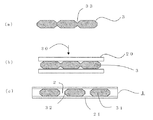
図6は、本発明の実施の形態2における、熱伝導シートの製造方法の概略を示す工程図である。
まず、図6(a)に示すように、上記熱伝導性を有するシート状または板状の薄体3の表面に溝33を形成し、図6(b)に示すように、上記薄体3の両面に樹脂組成物2からなる樹脂層20を設け、上記薄体3の少なくとも一方の面から上記樹脂層20に圧力30を加えることにより応力を利用して、薄体3を薄体片31に分断すると同時に、図6(c)に示すように、薄体片31の分断面32の間に樹脂組成物2を介在させ、薄体片31に分断された状態でシートを形成する。
本実施の形態の熱伝導シート1の製造方法においては、上記のように薄体3の表面に溝33を設け容易に分断されるようにすることにより、上記薄体3を薄体片31に分断する第1の工程と、上記薄体片31の分断面(側面)32の間に樹脂組成物2を介在させ、上記側面の間を接着してシートとする第2の工程とを同時に施すことができる。
FIG. 6 is a process diagram showing an outline of a method for manufacturing a heat conductive sheet in
First, as shown in FIG. 6A, a groove 33 is formed on the surface of the sheet-like or plate-like
In the manufacturing method of the heat
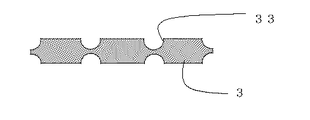
本実施の形態における第1の工程において、薄体3に分断用の溝33を設けると、上記溝33の側面にかかる圧力で、薄体3の分断を制御良くかつ容易に行うことができるが、上記溝33としては、図6(a)に示すように溝33の幅方向の断面形状がV字状のものの他に、図7の、本発明の実施の形態2における、別の熱伝導シートの製造方法において用いる薄体3の断面形状に示すように、溝33の幅方向の断面形状が半円状のものを用いても同様の効果がある。
つまり、図6(a)に示す断面形状の薄体3を用いた場合は図5(a)に示す断面形状の薄体片31に、図7に示す断面形状の薄体3を用いた場合は図5(c)に示す断面形状の薄体片31に分断される。
また、図6(a)に示すように、薄体3の両面に溝33を形成すると、分断がより容易となるが、薄体3の少なくとも一方の表面に形成しても分断することは可能であり、この場合は、図5(d)に示す断面形状の薄体片31に分断される。薄体3の片面のみに溝33を形成する場合は、熱伝導シート1を用いる際に、発熱体を搭載する側に溝33を形成することにより、薄体片31が効率よく発熱体から伝わった熱を広げることができる。In the first step of the present embodiment, when the dividing groove 33 is provided in the
That is, when the cross-sectional
Further, as shown in FIG. 6A, when the grooves 33 are formed on both surfaces of the
本実施の形態の熱伝導シート1の製造方法により、熱伝導シート1の厚さは、薄体3の厚さと樹脂組成物2の量によってコントロールすることができ、熱伝導シート1の所定の厚さに近い厚さの薄体3を用いることで、薄くて熱伝導率が高い熱伝導シート1を容易に製造することができる。
According to the manufacturing method of the heat
表2に、本実施の形態の熱伝導シート1の製造方法において用いる、熱伝導性を有するシート状または板状の薄体3の材料、厚さ、上記薄体3に設けた幅方向の断面がV字状である溝33におけるV字の頂角(V溝角度)および薄体3を分断するに要する圧力と、樹脂組成物2の組成および薄体片31上の表面樹脂層21の厚さ(表面厚)、並びに熱伝導シート1の絶縁耐圧を示す。
つまり、樹脂組成物2としてAl2O3(アルミナ)フィラーを充填したエポキシ樹脂を、上記薄体3として0.635mm厚のAlN(窒化アルミ)のセラミックス板を用い、表2に示すように、頂角が10°〜160°のV字状の溝33を深さ0.2mmで設け、表2に示す圧力を加えて分断することにより、上記のようにして実施の形態2−1〜実施の形態2−6の熱伝導シート1を製造し、絶縁耐圧を測定した。
この場合、樹脂組成物2は各薄体片31の間に介在するとともに薄体片31の表面にも渡り表面樹脂層21(表面厚)となり接着層として用いられる。この表面樹脂層21の最終的な厚さを決めるのが上記樹脂層20にかける圧力30と樹脂組成物2に充填されているフィラーの粒径であり、例えば上記表面樹脂層21を200μm以下とする場合には上記フィラーの粒度分布を考慮して最大で200μmを越えないようにする。また、上記接着層を100μm以下に薄くしたい場合には燐片状の窒化ホウ素フィラーを充填し、上記圧力30を10MPa以上にするか、フィラーの粒度分布の最大値が100μmであるものを充填する。なお、表2に示す熱伝導シート1における、薄体片31の大きさは10mm角、各薄体片31の間隔は0.5mmである。Table 2 shows the material and thickness of the sheet-like or plate-like
That is, an epoxy resin filled with an Al 2 O 3 (alumina) filler as the
In this case, the
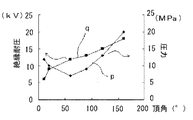
図8は、表2に基づいて得られたものであるが、図8において、pは本実施の形態の熱伝導シート1の製造方法において、薄体3に設けた上記V字状の溝33のV字の頂角と、薄体3を薄体片31へ分断するに要する圧力との関係を示し、qは上記頂角と熱伝導シート1の絶縁耐圧との関係を示す。
図8に示すように、上記頂角が20°未満では薄体3を分割するための圧力が増すとともに、絶縁耐圧の低下が顕著になる。また、160°を越えると分割するための圧力が工業的に実施するには大きくなり過ぎ、溝33以外のところでもクラックが生じる危険性があるため、V字状の溝33のV字の頂角は20°以上、160°以下が好ましい。
さらに、V字の頂角が60°以上では絶縁耐圧性に優れ、120°以下では分断に要する圧力が小さくなるため、V字状の溝33のV字の頂角は60°以上、120°以下であるのがより好ましい。
なお、薄体3としてAl2O3(アルミナ)またはBN(窒化ホウ素)等のセラミックス板を用いても、また、薄体3の厚さが0.1mm以上、2mm以下の範囲で、溝33の深さが0.05mm以上、0.4mm以下の範囲のものを用いても本実施の形態と同様の結果が得られた。FIG. 8 is obtained based on Table 2. In FIG. 8, p is the V-shaped groove 33 provided in the
As shown in FIG. 8, when the apex angle is less than 20 °, the pressure for dividing the
Furthermore, when the V-shaped apex angle is 60 ° or more, the insulation withstand voltage is excellent, and when the V-shaped apex angle is 120 ° or less, the pressure required for cutting is small. The following is more preferable.
In addition, even if a ceramic plate such as Al 2 O 3 (alumina) or BN (boron nitride) is used as the
表3に、本実施の形態による別の熱伝導シートにおいて、薄体片31の材料、厚さおよび熱伝導シート1の表面積における薄体片31の占有面積率と、樹脂組成物2の組成および薄体片31上の表面樹脂層21の厚さ(表面厚)と、熱伝導シート1の熱伝導率を示す。
つまり、熱伝導性を有する薄体3としてAlN(窒化アルミ)またはAl2O3(アルミナ)のセラミックス板を、樹脂組成物2としてAl2O3(アルミナ)フィラーまたはBN(窒化ホウ素)を充填したエポキシ樹脂を用い、上記のようにして実施の形態2−7〜実施の形態2−19の熱伝導シート1を製造し、上記熱伝導シート1の表面積における薄体片31の占める面積(占有面積)と熱伝導シート1の熱伝導率を測定した。In Table 3, in another heat conductive sheet according to the present embodiment, the occupation ratio of the
That is, a ceramic plate of AlN (aluminum nitride) or Al 2 O 3 (alumina) is filled as the
表3に示すように、本実施の形態による熱伝導シート1は熱伝導率に優れていることがわかる。また、上記熱伝導シート1は、製造工程中および「−40℃での30分間保持と125℃での30分間保持」を1サイクルとして、300サイクルのヒートサイクル試験を施しても、セラミックス板にクラックが生じなかった。
As shown in Table 3, it can be seen that the thermal
実施の形態3.
図9(a)〜(f)は、本発明の実施の形態3における、熱伝導シートの製造方法の概略を示す工程図であり、実施の形態2において、第1の工程における薄体3の分断を、保持シート5を用いて行う場合である。
図9(a)に示すように、まず、溝33を設けた薄体3を例えば粘着シート等の保持シート5に保持し、第1の工程である図9(b)に示すように、保持シート5を面方向に引張る力40によって薄体3を分断して薄体片31を得る。この場合、例えば、薄体3をセラミックス板のようにもろいものにしたり、薄体3の表面に溝33を設けたり、薄体3の厚さを例えば100μm程度に薄くすることにより分断を容易に行うことができる。
その後、図9(c)に示すように、薄体片31上に樹脂組成物2からなる樹脂層20を設けて、上記樹脂層20に圧力30をかけて、第2の工程である図9(d)に示すように、薄体片31の分断面32間に樹脂組成物2を介在させ、図9(e)に示すように、その後保持シート5を取り除く。熱伝導シート1に接着性を持たせる場合には保持シート5を取り除いた面に樹脂を塗布またはプレスし、上記樹脂を半硬化状態にしておく。樹脂を最終的に半硬化状態にしておくには、樹脂シートをプレスして半硬化状態で止めておいたり、液状樹脂を塗布した後に半硬化状態で止めておく。
また、図9(f)に示すように、保持シート5を取り除いた面に、樹脂組成物2により銅箔4を接着させても良く、銅箔4が片面に存在することによって熱伝導シート1の耐湿性が向上する。
FIGS. 9A to 9F are process diagrams showing an outline of a method for manufacturing a heat conductive sheet in
As shown in FIG. 9A, first, the
Thereafter, as shown in FIG. 9C, the
Moreover, as shown in FIG.9 (f), you may adhere the
実施の形態4.
本発明の実施の形態4の熱伝導シート1の製造方法は、実施の形態2において、薄体3の分断を、薄体3の少なくとも一方の表面に樹脂組成物2からなる樹脂層20を半硬化状態で接着させておき、加熱と冷却とを交互に与えることによって、上記薄体3と樹脂組成物2からなる樹脂層20との熱膨張率の差を利用して分断を行う他は、実施の形態2と同様にして熱伝導シート1を製造する方法である。
なお、本実施の形態においても、薄体3の少なくとも一方の表面に溝33を形成することにより、容易に制御良く分断することができる。
The manufacturing method of the heat
Also in the present embodiment, by forming the groove 33 on at least one surface of the
実施の形態5.
図10は、本発明の実施の形態5における、熱伝導シートの概略構成を示す上面図とこれに搭載された発熱体(被熱伝導体)の配置図であり、上記発熱体6は、上記熱伝導シート1によってこれからの熱が伝導され放出されるべき被熱伝導体である。
つまり、図10(a)に表面樹脂層21を透視して示すように、本実施の形態の熱伝導シート1は、薄体片31の間隔が等間隔でなく、搭載した発熱体6の直下部分(搭載領域)における薄体片31の間隔を、発熱体6の直下から離れたところ(非搭載領域)における薄体片31の間隔より狭く集中させて配置したものである他は、実施の形態1の熱伝導シート1と同様である。
本実施の形態の熱伝導シート1においては、薄体片31が上記のように配置しているので、薄体片31の間隔が熱伝導シート1全体で均等で、上記発熱体6の直下部分のように狭く密に詰まっている場合に比べて、熱伝導シート1とこの熱伝導シート1と接着する部材との熱膨張率の差などによる応力をより緩和することができる。
但し、薄体片31を密に詰める場合でも、薄体片31間の間隔は0.1mm以上、1mm以下であることが好ましく、一方、発熱体6直下でない部分における薄体片31の間隔がより広い部分においても、薄体片31間の間隔は0.5mm以上、3mm以下であるのが好ましい。
なお、熱伝導シート1に直接発熱体6が搭載されていることに限定されず、発熱体6と熱伝導シート1の間に金属やセラミックス板が介在していてもよい。
FIG. 10 is a top view showing a schematic configuration of a heat conductive sheet and a layout diagram of a heating element (heated conductor) mounted thereon in
That is, as shown in FIG. 10A through the
In the heat
However, even when the
The
実施の形態6.
図11は、本発明の実施の形態6における、熱伝導シートの概略構成を示す上面図とこれに搭載された発熱体(被熱伝導体)の配置図である。
つまり、図11(a)に表面樹脂層21を透視して示すように、本実施の形態の熱伝導シート1は、薄体片31の間隔は等間隔であるが、搭載された発熱体6の直下部分(搭載領域)における薄体片31の大きさを、発熱体6の直下部分から離れたところ(非搭載領域)における薄体片31の大きさより大きくして配置したものである他は、実施の形態1の熱伝導シート1と同様で、これによって熱抵抗が低減し発熱体からの熱を効率よく放熱することができる。
FIG. 11 is a top view showing a schematic configuration of a heat conductive sheet and a layout diagram of a heating element (heated conductor) mounted thereon, in
That is, as shown in FIG. 11A through the
なお、薄体片31の形状は上記実施の形態に示した形状に限定されず、熱伝導シート1の上面から見て三角形または六角形になるように、上記溝33を設けることにより、薄体片31の大きさや形状を調整する。
In addition, the shape of the
実施の形態7.
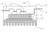
図12は、本発明の実施の形態7における、パワーモジュールの概略構成を示す断面図であり、実施の形態1〜6のいずれかの熱伝導シート1を用いたものである。
本実施の形態のパワーモジュール7は、パワー半導体素子6がリードフレーム8とつながったヒートシンク9に搭載され、上記実施の形態1〜6の熱伝導シート1がヒートシンク9とヒートスプレッダ11とに接着し、上記構成部材がモールド樹脂10で封止された構造となっている。
なお、実施の形態1〜6の熱伝導シート1を半硬化状態の固形シートとしてヒートシンク9とヒートスプレッダ11の間に配置し、加熱硬化すれば、生産性よく接着できる。また、熱伝導シート1の硬化反応によるヒートシンク9とヒートスプレッダ11との接着工程は、モールド樹脂10による封止工程で同時に行ってもよい。
本実施の形態のパワーモジュール7に対して、「−40℃での30分間保持と125℃での30分間保持」を1サイクルとして、300サイクルを施したヒートサイクル試験を施したところ、ヒートシンク9とヒートスプレッダ11とを接着する熱伝導シート1における薄体片31に割れが認められず放熱性を維持することができ、高容量化が可能となった。
FIG. 12: is sectional drawing which shows schematic structure of the power module in
The
In addition, if the heat
The
本発明による熱伝導シート1は、例えば、パワー半導体素子等の発熱体を搭載したパワモジュール等の半導体装置に用いることができる。
The heat
Claims (9)
複数の上記薄体片の側面の間に介在し、上記側面間を接着してシートとする樹脂組成物とを備えた熱伝導シートであって、
複数の上記薄体片の側面間の間隔が、0.1mm以上、3mm以下であり、
被熱伝導体の搭載領域における上記薄体片の間隔が、上記被熱伝導体の非搭載領域における上記薄体片の間隔より狭いことを特徴とする熱伝導シート。 A plurality of thin pieces provided adjacent to each other and having thermal conductivity;
A heat conductive sheet provided between the side surfaces of the plurality of thin body pieces, and a resin composition that bonds the side surfaces to form a sheet,
The interval between the side surfaces of the plurality of thin pieces is 0.1 mm or more and 3 mm or less,
Intervals of the thin magnetic pieces in the mounting region of the Hinetsu conductor, the heat conductive sheet characterized narrower than the spacing of the thin magnetic pieces in the non-mounting region of the Hinetsu conductor.
複数の上記薄体片の側面の間に介在し、上記側面間を接着してシートとする樹脂組成物とを備えた熱伝導シートであって、
上記薄体片の面方向の大きさが3mm角以上、25mm角以下であり、
被熱伝導体の搭載領域における上記薄体片の面方向の大きさが、上記被熱伝導体の非搭載領域における上記薄体片の大きさより大であることを特徴とする熱伝導シート。 A plurality of thin pieces provided adjacent to each other and having thermal conductivity;
A heat conductive sheet provided between the side surfaces of the plurality of thin body pieces, and a resin composition that bonds the side surfaces to form a sheet,
The size in the surface direction of the thin piece is 3 mm square or more and 25 mm square or less,
Hinetsu size in the plane direction of the conductor the thin magnetic pieces in the mounting area of the heat conduction sheet you being a larger than the size of the thin magnetic pieces in the non-mounting region of the Hinetsu conductor.
上記溝が形成された熱伝導性を有するシート状または板状の上記薄体を分断して複数の薄体片を得る工程と、
複数の上記薄体片の分断面間に樹脂組成物を介在させて、上記薄体片を接着してシートとする工程と
を備えたことを特徴とする熱伝導シートの製造方法。Forming a groove on at least one surface of the thin body;
Dividing the sheet-like or plate-like thin body having heat conductivity in which the grooves are formed to obtain a plurality of thin body pieces;
A plurality of the resin composition is interposed between divided surfaces of the thin magnetic pieces, the manufacture of the heat conduction sheet you comprising the steps as <br/> of a sheet by bonding the thin magnetic piece Method.
上記複数の薄体片の分断面間に樹脂組成物を介在させて、上記薄体片を接着してシートとする第2の工程とを備え、
上記薄体の少なくとも一方の面に樹脂組成物からなる樹脂層を設け、上記薄体の少なくとも一方から上記樹脂層に圧力をかけて上記第1の工程と上記第2の工程とを同時に施すことを特徴とする熱伝導シートの製造方法。 A first step of dividing a sheet-like or plate-like thin body having thermal conductivity to obtain a plurality of thin body pieces;
A second step of interposing the resin composition between the cross sections of the plurality of thin pieces and bonding the thin pieces into a sheet;
On at least one surface of the thin body resin layer provided comprising a resin composition, from at least one of the thin body by applying pressure to the resin layer is subjected to the above-described first step and the second step simultaneously method for manufacturing a heat conducting sheet you characterized.
複数の上記薄体片の分断面間に樹脂組成物を介在させて、上記薄体片を接着してシートとする工程と
を備えたことを特徴とする熱伝導シートの製造方法。A step of holding a thin body on a holding sheet, and by pulling the holding sheet in a plane direction, dividing the sheet-like or plate-like thin body having thermal conductivity to obtain a plurality of thin body pieces; ,
A process for producing a heat conductive sheet, comprising: a step of interposing a resin composition between the divided sections of a plurality of the thin pieces and bonding the thin pieces to form a sheet. .
Applications Claiming Priority (1)
| Application Number | Priority Date | Filing Date | Title |
|---|---|---|---|
| PCT/JP2005/013461 WO2007010615A1 (en) | 2005-07-22 | 2005-07-22 | Heat conducting sheet, method for manufacturing such heat conducting sheet, and power module using heat conducting sheet |
Publications (2)
| Publication Number | Publication Date |
|---|---|
| JPWO2007010615A1 JPWO2007010615A1 (en) | 2009-01-29 |
| JP4582144B2 true JP4582144B2 (en) | 2010-11-17 |
Family
ID=37668504
Family Applications (1)
| Application Number | Title | Priority Date | Filing Date |
|---|---|---|---|
| JP2007525482A Expired - Fee Related JP4582144B2 (en) | 2005-07-22 | 2005-07-22 | HEAT CONDUCTIVE SHEET, ITS MANUFACTURING METHOD, AND POWER MODULE USING HEAT CONDUCTIVE SHEET |
Country Status (3)
| Country | Link |
|---|---|
| JP (1) | JP4582144B2 (en) |
| TW (1) | TW200705627A (en) |
| WO (1) | WO2007010615A1 (en) |
Families Citing this family (8)
| Publication number | Priority date | Publication date | Assignee | Title |
|---|---|---|---|---|
| US20090279300A1 (en) * | 2006-05-31 | 2009-11-12 | Denki Kagaku Kogyo Kabushiki Kaisha | Led light source unit |
| CN101595573A (en) * | 2007-01-30 | 2009-12-02 | 电气化学工业株式会社 | The led light source unit |
| JP4854571B2 (en) * | 2007-04-06 | 2012-01-18 | 三菱電機株式会社 | Semiconductor laser device |
| JP2010073965A (en) * | 2008-09-19 | 2010-04-02 | Denso Corp | Semiconductor cooling unit |
| JP5484429B2 (en) * | 2011-11-18 | 2014-05-07 | 三菱電機株式会社 | Power converter |
| JP5877056B2 (en) * | 2011-12-22 | 2016-03-02 | 日本シイエムケイ株式会社 | Insulated heat dissipation board for power module and manufacturing method thereof |
| JP6813473B2 (en) * | 2017-12-26 | 2021-01-13 | 公益財団法人鉄道総合技術研究所 | Heat dissipation board and its manufacturing method |
| JP2019176060A (en) * | 2018-03-29 | 2019-10-10 | 帝人株式会社 | Electrically insulative heat conductive sheet and method of manufacturing the same |
Citations (2)
| Publication number | Priority date | Publication date | Assignee | Title |
|---|---|---|---|---|
| WO1995002313A1 (en) * | 1993-07-06 | 1995-01-19 | Kabushiki Kaisha Toshiba | Heat dissipating sheet |
| JP2004172286A (en) * | 2002-11-19 | 2004-06-17 | Kyocera Chemical Corp | Heat conductive sheet |
-
2005
- 2005-07-22 WO PCT/JP2005/013461 patent/WO2007010615A1/en active Application Filing
- 2005-07-22 JP JP2007525482A patent/JP4582144B2/en not_active Expired - Fee Related
- 2005-09-13 TW TW094131420A patent/TW200705627A/en not_active IP Right Cessation
Patent Citations (2)
| Publication number | Priority date | Publication date | Assignee | Title |
|---|---|---|---|---|
| WO1995002313A1 (en) * | 1993-07-06 | 1995-01-19 | Kabushiki Kaisha Toshiba | Heat dissipating sheet |
| JP2004172286A (en) * | 2002-11-19 | 2004-06-17 | Kyocera Chemical Corp | Heat conductive sheet |
Also Published As
| Publication number | Publication date |
|---|---|
| JPWO2007010615A1 (en) | 2009-01-29 |
| WO2007010615A1 (en) | 2007-01-25 |
| TWI294175B (en) | 2008-03-01 |
| TW200705627A (en) | 2007-02-01 |
Similar Documents
| Publication | Publication Date | Title |
|---|---|---|
| JP4582144B2 (en) | HEAT CONDUCTIVE SHEET, ITS MANUFACTURING METHOD, AND POWER MODULE USING HEAT CONDUCTIVE SHEET | |
| JP6224171B2 (en) | Manufacturing method of semiconductor module | |
| KR101419627B1 (en) | Substrate for power module, and power module | |
| JP6336138B2 (en) | Semiconductor device | |
| JP6462899B2 (en) | Heat dissipation plate material for high output elements | |
| JP2005260181A (en) | Resin-sealed semiconductor device and manufacturing method thereof | |
| CN109791918B (en) | Heat radiation structure of circuit device | |
| JP6643975B2 (en) | Method for manufacturing semiconductor device | |
| JP6508193B2 (en) | Semiconductor device manufacturing method and semiconductor device | |
| US11935811B2 (en) | Baseplate for a semiconductor module and method for producing a baseplate | |
| JP2010192591A (en) | Power semiconductor device and method of manufacturing the same | |
| KR20160108307A (en) | Electronic circuit device | |
| KR20200138262A (en) | Method for manufacturing a bonded body for an insulated circuit board and a bonded body for an insulated circuit board | |
| JP2017139325A (en) | Semiconductor module and manufacturing method for semiconductor module | |
| JP2014207490A (en) | Insulating substrate, process of manufacturing the same, semiconductor module, and semiconductor device | |
| JP7072624B1 (en) | Power semiconductor devices and methods for manufacturing power semiconductor devices | |
| EP3416186A1 (en) | Semiconductor substrate arrangement with a connection layer with regions of different porosity and method for producing the same | |
| JP5630375B2 (en) | Insulating substrate, manufacturing method thereof, semiconductor module, and semiconductor device | |
| EP3627546A1 (en) | Power semiconductor module arrangement | |
| JP5928324B2 (en) | Power semiconductor device | |
| CN110943057B (en) | Power semiconductor module device | |
| JP7135951B2 (en) | Manufacturing method of insulated circuit board | |
| JP6825411B2 (en) | Insulation circuit board, manufacturing method of insulation circuit board | |
| US20230154811A1 (en) | Semiconductor device and method of manufacturing semiconductor device | |
| JP7063559B2 (en) | Base plate and power module |
Legal Events
| Date | Code | Title | Description |
|---|---|---|---|
| A131 | Notification of reasons for refusal |
Free format text: JAPANESE INTERMEDIATE CODE: A131 Effective date: 20100413 |
|
| A521 | Request for written amendment filed |
Free format text: JAPANESE INTERMEDIATE CODE: A523 Effective date: 20100608 |
|
| TRDD | Decision of grant or rejection written | ||
| A01 | Written decision to grant a patent or to grant a registration (utility model) |
Free format text: JAPANESE INTERMEDIATE CODE: A01 Effective date: 20100803 |
|
| A01 | Written decision to grant a patent or to grant a registration (utility model) |
Free format text: JAPANESE INTERMEDIATE CODE: A01 |
|
| A61 | First payment of annual fees (during grant procedure) |
Free format text: JAPANESE INTERMEDIATE CODE: A61 Effective date: 20100816 |
|
| R151 | Written notification of patent or utility model registration |
Ref document number: 4582144 Country of ref document: JP Free format text: JAPANESE INTERMEDIATE CODE: R151 |
|
| FPAY | Renewal fee payment (event date is renewal date of database) |
Free format text: PAYMENT UNTIL: 20130910 Year of fee payment: 3 |
|
| R250 | Receipt of annual fees |
Free format text: JAPANESE INTERMEDIATE CODE: R250 |
|
| R250 | Receipt of annual fees |
Free format text: JAPANESE INTERMEDIATE CODE: R250 |
|
| R250 | Receipt of annual fees |
Free format text: JAPANESE INTERMEDIATE CODE: R250 |
|
| R250 | Receipt of annual fees |
Free format text: JAPANESE INTERMEDIATE CODE: R250 |
|
| LAPS | Cancellation because of no payment of annual fees |