JP4579528B2 - Image forming apparatus - Google Patents
Image forming apparatus Download PDFInfo
- Publication number
- JP4579528B2 JP4579528B2 JP2003405027A JP2003405027A JP4579528B2 JP 4579528 B2 JP4579528 B2 JP 4579528B2 JP 2003405027 A JP2003405027 A JP 2003405027A JP 2003405027 A JP2003405027 A JP 2003405027A JP 4579528 B2 JP4579528 B2 JP 4579528B2
- Authority
- JP
- Japan
- Prior art keywords
- identification tag
- recording medium
- wireless identification
- image
- unit
- Prior art date
- Legal status (The legal status is an assumption and is not a legal conclusion. Google has not performed a legal analysis and makes no representation as to the accuracy of the status listed.)
- Expired - Fee Related
Links
Images


Classifications
-
- G—PHYSICS
- G03—PHOTOGRAPHY; CINEMATOGRAPHY; ANALOGOUS TECHNIQUES USING WAVES OTHER THAN OPTICAL WAVES; ELECTROGRAPHY; HOLOGRAPHY
- G03G—ELECTROGRAPHY; ELECTROPHOTOGRAPHY; MAGNETOGRAPHY
- G03G15/00—Apparatus for electrographic processes using a charge pattern
- G03G15/65—Apparatus which relate to the handling of copy material
-
- G—PHYSICS
- G03—PHOTOGRAPHY; CINEMATOGRAPHY; ANALOGOUS TECHNIQUES USING WAVES OTHER THAN OPTICAL WAVES; ELECTROGRAPHY; HOLOGRAPHY
- G03G—ELECTROGRAPHY; ELECTROPHOTOGRAPHY; MAGNETOGRAPHY
- G03G2215/00—Apparatus for electrophotographic processes
- G03G2215/00362—Apparatus for electrophotographic processes relating to the copy medium handling
- G03G2215/00443—Copy medium
- G03G2215/00447—Plural types handled
-
- G—PHYSICS
- G03—PHOTOGRAPHY; CINEMATOGRAPHY; ANALOGOUS TECHNIQUES USING WAVES OTHER THAN OPTICAL WAVES; ELECTROGRAPHY; HOLOGRAPHY
- G03G—ELECTROGRAPHY; ELECTROPHOTOGRAPHY; MAGNETOGRAPHY
- G03G2215/00—Apparatus for electrophotographic processes
- G03G2215/00362—Apparatus for electrophotographic processes relating to the copy medium handling
- G03G2215/00535—Stable handling of copy medium
- G03G2215/00611—Detector details, e.g. optical detector
-
- G—PHYSICS
- G03—PHOTOGRAPHY; CINEMATOGRAPHY; ANALOGOUS TECHNIQUES USING WAVES OTHER THAN OPTICAL WAVES; ELECTROGRAPHY; HOLOGRAPHY
- G03G—ELECTROGRAPHY; ELECTROPHOTOGRAPHY; MAGNETOGRAPHY
- G03G2215/00—Apparatus for electrophotographic processes
- G03G2215/00362—Apparatus for electrophotographic processes relating to the copy medium handling
- G03G2215/00535—Stable handling of copy medium
- G03G2215/00717—Detection of physical properties
- G03G2215/00751—Detection of physical properties of sheet type, e.g. OHP
Description
本発明は、画像形成技術に関し、特に、電子写真方式あるいは静電記録方式等により形成された潜像担持体上のトナー像を記録媒体に転写して画像を形成する画像形成装置、またはインクジェット記録方式によって直接記録媒体に画像を形成する画像形成装置及びその制御方法に関するものである。 The present invention relates to an image forming technique, and in particular, an image forming apparatus for transferring a toner image on a latent image carrier formed by an electrophotographic method or an electrostatic recording method onto a recording medium, or ink jet recording. The present invention relates to an image forming apparatus that directly forms an image on a recording medium by a method and a control method thereof.
給紙ユニットに複数枚格納された普通紙に代表される記録媒体に対し、転写部材上のトナー潜像画像を転写し、その後に熱定着させて複写画像形成を行う電子写真画像形成装置において、複写画像形成された画像情報の管理を行うことは、その複写画像に関する情報の閲覧・再利用といった観点で重要な問題である。その際、複写元の画像情報が電子データである場合には、電子情報のデータベース化等により画像情報の重要度、著作者・所有者、作成時期、キーワードなどの様々な付帯情報を、画像情報とともに一括管理することができ、画像情報の検索や、その更新などを容易に行なうことが可能となり、情報の閲覧・再利用という観点で有効であった(例えば、特許文献1を参照。)。 In an electrophotographic image forming apparatus that forms a copy image by transferring a toner latent image on a transfer member to a recording medium represented by plain paper stored in a plurality of sheets in a paper supply unit, and then thermally fixing the image. Management of image information on which a copied image is formed is an important problem from the viewpoint of browsing and reusing information on the copied image. At that time, if the image information of the copy source is electronic data, various incidental information such as the importance of the image information, author / owner, creation time, keyword, etc. can be obtained by creating a database of the electronic information. In addition, the image information can be managed and can be easily searched for and updated, which is effective from the viewpoint of browsing and reusing information (see, for example, Patent Document 1).
一方、RFID(Radio Frequency Identification)タグ(以下、「無線識別タグ」という。)を利用した情報と物とを対応付ける管理も着目されており、例えば、特許文献2では、記録媒体に無線識別タグを実装して複写機、プリンタに応用する技術もある。
しかしながら、元となるデータが電子データではなく枚葉の紙媒体(以下、「紙葉体」という。)に印刷された画像情報である場合や、一旦、画像形成装置によって電子データが記録媒体へと印刷された後の画像情報については、先に述べたような付帯情報を画像情報と共に対応づけることができなくなるために、電子情報のデータベースで一括管理することができなくなる。そのため印刷された画像情報に関する情報の閲覧や再利用をする場合には大変困難なものとなっていた。 However, when the original data is not electronic data but image information printed on a sheet of paper medium (hereinafter referred to as “paper sheet”), or once the electronic data is transferred to the recording medium by the image forming apparatus. With respect to the image information after printing, the supplementary information as described above cannot be associated with the image information and cannot be collectively managed in the database of electronic information. For this reason, it is very difficult to browse and reuse information about printed image information.
例えば、電子データに基づいて一旦、記録媒体に印刷した場合、その媒体からその元となる電子データを検索することは、その電子データを検索するための情報が無い限りできないため、印刷された画像情報を電子データとして再利用する場合には、印刷された媒体の画像情報を再度電子化する必要が生じる。更に、元となる電子データがその後の編集により、変更、修正された場合、編集の結果は、編集の以前に印刷された画像情報に反映される術がないため、この場合には、印刷された画像情報の再度の電子化に加えて、再度の編集操作を加える必要が生じ、重複した作業負担を操作者に強いることとなっていた。 For example, once printed on a recording medium based on electronic data, the original electronic data cannot be retrieved from the medium unless there is information for retrieving the electronic data. When the information is reused as electronic data, it is necessary to digitize the image information of the printed medium again. Furthermore, if the original electronic data is changed or modified by subsequent editing, the editing result cannot be reflected in the image information printed before editing. In addition to the digitization of the image information, it is necessary to perform another editing operation, which imposes an overlapping work burden on the operator.
また、無線識別タグを利用する場合でも、予めメモリに格納されているデータを読み出すだけのリードオンリータイプのもの(uチップ)に比べ、データをメモリから読み出し、書き込むことができるリードライト仕様のものは経済的にはまだ高価であり、かつ、信頼性の面でも、予め記録媒体に装着して無線識別タグを用いるには問題も多い。 Also, even when using a wireless identification tag, it has a read / write specification that can read and write data from the memory compared to a read-only type (u-chip) that only reads data stored in the memory in advance. Is economically expensive and has many problems in terms of reliability when it is mounted on a recording medium in advance and a wireless identification tag is used.
例えば、トナー像を記録媒体に転写して画像を形成する画像形成装置において、記録媒体を定着器に通す際には、無線識別タグは記録媒体と共に、高温環境下に置かれることになり、無線識別タグを構成するデバイスが物理的に破壊することや、画像形成装置の内部における転写等で印加される高電界によりデバイスの絶縁破壊が生じて無線識別タグを構成するデバイスが動作しなくなるなど、予め記録媒体に無線識別タグを装着した状態での画像形成は、無線識別タグの信頼性の面で困難な状況にある。また、無線識別タグを装着した記録媒体は、一般には未だ普及しておらず、このような記録媒体を特注して事前に準備することも困難な現状にある。 For example, in an image forming apparatus that forms an image by transferring a toner image to a recording medium, the wireless identification tag is placed in a high temperature environment together with the recording medium when the recording medium is passed through a fixing device. The device constituting the identification tag physically breaks down, or the device constituting the wireless identification tag becomes inoperable due to the breakdown of the device caused by the high electric field applied by the transfer inside the image forming apparatus, etc. Image formation in a state in which a wireless identification tag is mounted on a recording medium in advance is difficult in terms of reliability of the wireless identification tag. In addition, a recording medium equipped with a wireless identification tag is not yet widely used, and it is difficult to specially prepare such a recording medium in advance.
通常市販されている記録媒体を利用し、無線識別タグの信頼性が確保できるように、新たに無線識別タグを記録媒体に装着することは重要な課題である。 It is an important issue to newly attach a wireless identification tag to a recording medium so that the reliability of the wireless identification tag can be secured by using a commercially available recording medium.
本発明は、上記課題に鑑みて、画像データの一元的な管理を可能にし、画像データの検索、再利用等を可能にする画像形成技術の提供を目的とするものであり、主として以下の構成を有する。 SUMMARY OF THE INVENTION In view of the above problems, the present invention has an object to provide an image forming technique that enables unified management of image data and enables search, reuse, and the like of image data. Have
すなわち、搬送されてくる記録媒体上に、画像データに基づいて画像形成手段が画像を形成する画像形成装置であって、
前記記録媒体上の画像と前記画像データとを対応付けるための管理情報を準備し、当該管理情報に従い前記画像形成手段の動作を制御する制御手段と、
前記画像形成手段によって記録媒体上に形成されたトナーの画像を熱定着させる定着手段と、
前記定着手段よりも前記記録媒体の搬送方向下流側に設けられ、前記トナーの画像が熱定着された記録媒体に、無線通信によりデータの送受信が可能な送受信部と当該データの保持が可能なデータ保持部とを有する無線識別タグを貼付する貼付手段と、
前記定着手段よりも前記記録媒体の搬送方向下流側に設けられ、前記貼付手段によって前記記録媒体に貼付された前記無線識別タグのデータ保持部に前記管理情報を、前記送受信部と無線通信をして書き込む通信手段と、
を備えることを特徴とする。
That is, on a recording medium conveyed, an image forming apparatus which forms an image forming means Gae image based on the image data,
Control means for preparing management information for associating the image on the recording medium with the image data, and controlling operation of the image forming means according to the management information;
Fixing means for thermally fixing an image of the toner formed on the recording medium by the image forming means;
A transmission / reception unit capable of transmitting / receiving data by wireless communication to / from a recording medium provided on the downstream side of the fixing unit in the conveyance direction of the recording medium and on which the toner image is thermally fixed, and data capable of holding the data Affixing means for affixing a radio identification tag having a holding unit;
Provided downstream of the fixing unit in the transport direction of the recording medium, and wirelessly communicates the management information to the data holding unit of the wireless identification tag attached to the recording medium by the attaching unit. Communication means to write,
It is characterized by providing.
本発明によれば、画像形成に伴い、不揮発性メモリを備えた無線識別タグを画像が形成された記録媒体に装着し、その画像を管理するための情報を無線識別タグの不揮発性メモリに記憶させることで、記録媒体に形成された画像と、データベースで一元的に管理されている情報との対応づけを可能にする。これにより、元となる画像データの検索、再利用が可能になる。 According to the present invention, along with image formation, a wireless identification tag having a nonvolatile memory is attached to a recording medium on which an image is formed, and information for managing the image is stored in the nonvolatile memory of the wireless identification tag. By doing so, it is possible to associate the image formed on the recording medium with the information that is centrally managed in the database. As a result, the original image data can be searched and reused.
(第1実施形態)
図1乃至図3は本発明が提供する画像形成技術を適用した画像形成装置の構成を説明する図である。以下、図面を参照しつつその基本的な構成を説明する。
(First embodiment)
1 to 3 are diagrams illustrating the configuration of an image forming apparatus to which an image forming technique provided by the present invention is applied. The basic configuration will be described below with reference to the drawings.
<カラーリーダ部の構成>
まず、カラーリーダ部の構成について説明する。
<Configuration of color reader unit>
First, the configuration of the color reader unit will be described.
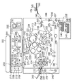
図1は画像形成装置の全体的な構成を示す図である。ここで、同図において101は画像撮像素子であるCCD、211はCCD101の実装された基板であり、200は画像形成装置の全体を制御する制御部である。212はディジタル画像処理部であり、201は原稿台ガラス(プラテン)、そして202は原稿給紙装置(DF)(なお、この原稿給紙装置202の代わりに不図示の鏡面圧板を装着する構成もある。)である。
FIG. 1 is a diagram illustrating an overall configuration of an image forming apparatus. In this figure, 101 is a CCD as an image pickup device, 211 is a substrate on which the
203及び204は原稿を照明する光源(ハロゲンランプ又は蛍光灯)、205及び206は光源203及び204の光を原稿に集光する反射傘である。207〜209はミラー、210は原稿からの反射光又は投影光をCCD101上に集光するレンズ、そして214は光源(203、204)と反射傘(205、206)とミラー207を収容するキャリッジである。
215はミラー208及び209を収容するキャリッジであり、213は他のデバイスとの外部インターフェイス(I/F)である。なお、キャリッジ214は速度Vで、キャリッジ215は速度V/2で、CCD101の電気的走査(主走査)方向に対して垂直方向(矢印の示す方向)に機械的に移動することによって、原稿の全面を走査(副走査)する。
制御部200は、図2に示すようにディジタル画像処理部212と外部I/F213、プリンタ制御I/F253に対してそれぞれ制御を行うための情報を、CPU391を介してやり取りする操作部392と、メモリ393によって構成されている。操作部392は操作者による処理内容の入力や操作者に対する処理に関する情報あるいは警告等を通知するためのタッチパネル付き液晶により構成される。メモリ393には、画像形成が正常に実行されたか否かを判定するためのデータとして、画像形成の元となる画像のデータを格納しておくことができる。このデータと、画像形成装置から排出された記録媒体上に形成された画像のデータとを比較することにより、画像形成が正常に終了したか否かを判定することができる。この処理に関しては、第2実施形態において詳細に説明する。
As shown in FIG. 2, the
また、外部I/F213は、画像データやコード情報などを画像形成装置外部の機器とやり取りするためのインターフェースであり、具体的には図4に示すようにファクシミリ装置481やLANインターフェース装置482、外部大容量記憶装置483などと接続することが可能である。なお、ファクシミリ装置481やLANインターフェース装置482、外部大容量記憶装置483との間で、画像データやコード情報の通信、及び通信の制御については、各接続装置であるファクシミリ装置481、LANインターフェース装置482や外部大容量記憶装置483と制御部200のCPU391との相互通信により行われる。
The external I /
原稿台ガラス201の下部には本実施形態の特徴である記録媒体である原稿に貼付けられた無線識別タグと無線通信を行うための無線識別タグ情報受信部217が配されている。この詳細については後述する。
A wireless identification tag
<ディジタル画像処理部>
次にディジタル画像処理部212の詳細について説明する。図3はディジタル画像処理部212の詳細な構成を示すブロック図である。原稿台ガラス201上の原稿は、光源(203、204)からの光を反射し、その反射光はCCD101に導かれて電気信号に変換される。ここで、CCD101はカラーセンサの場合、RGBのカラーフィルタが1ラインCCD上にRGB順にインラインに乗ったものでも、3ラインCCDで、それぞれRフィルタ・Gフィルタ・BフィルタをそれぞれのCCDごとに並べたものでも構わないし、フィルタがオンチップ化又は、フィルタがCCDと別構成になったものでも構わない。
<Digital image processing unit>
Next, details of the digital
そして、その電気信号(アナログ画像信号)は画像処理部212に入力され、クランプ&Amp.&S/H&A/D部102でサンプルホールド(S/H)され、アナログ画像信号のダークレベルを基準電位にクランプし、所定量に増幅され(上記処理順番は表記順とは限らない)、A/D変換されて、例えばRGB各8ビットのディジタル信号に変換される。
Then, the electric signal (analog image signal) is input to the
続いてRGB信号はシェーディング部103で、シェーディング補正及び黒補正が施される。補正後のRGB信号はさらに、つなぎ&MTF補正&原稿検知部104により処理される。ここで、CCD101が3ラインCCDの場合、つなぎ処理はライン間(R、G、Bライン関)の読取位置が異なるため、読取速度に応じてライン毎の遅延量を調整し、3ラインの読取位置が同じになるように、読み取りのタイミングが補正される。MTF補正は読取速度や変倍率によって読取のMTFが変るため、その変化を補正し、原稿検知は原稿台ガラス201上の原稿を走査することにより原稿サイズを認識する。読取位置のタイミングが補正されたデジタル信号は入力マスキング部105に入力され、入力マスキング部105は、CCD101の分光特性及び光源(203、204)及び反射傘(205、206)の分光特性を補正する。
Subsequently, the RGB signal is subjected to shading correction and black correction by the
入力マスキング部105の出力は外部I/F信号との切り換え可能なセレクタ106に入力される。セレクタ106から出力された信号は色空間圧縮&下地除去&LOG変換部107と下地除去部115に入力される。下地除去部115に入力された信号は下地除去された後、原稿中の原稿の黒い文字かどうかを判定する黒文字判定部116に入力され、原稿から黒文字信号を生成する。
The output of the
また、セレクタ106の出力が入力されるもう一方の色空間圧縮&下地除去&LOG変換部107では、色空間圧縮は読み取った画像信号がプリンタで再現できる範囲に入っているかどうか判定し、入っている場合はそのまま、入っていない場合は画像信号をプリンタで再現できる範囲に入るように補正する。そして、下地除去処理を行い、LOG変換でRGB信号からCMY信号に変換する。そして、黒文字判定部116で生成された信号とタイミングを補正するため色空間圧縮&下地除去&LOG変換部107の出力信号は遅延108でタイミングが調整される。
In the other color space compression & background removal &
この2種類の信号はモワレ除去部109でモワレが除去され、変倍処理部110で、主走査方向に変倍処理される。111はUCR&マスキング&黒文字反映部で、変倍処理部で処理された信号は、CMY信号についてはUCR処理でCMYK信号が生成され、マスキング処理部でプリンタの出力にあった信号に補正されると共に黒文字判定部116で生成された判定信号がCMYK信号にフィードバックされる。UCR&マスキング&黒文字反映部111で処理された信号はγ補正部112で濃度調整された後フィルタ部113でスムージング又はエッジ処理される。
The
<プリンタ部の構成>
続いて、説明を図1に戻し、画像形成装置の一例として、プリンタ部の構成について説明する。像担持体としての感光体ドラム(以下、単に「感光体」という)225は図示しないモータで矢印Aの方向に回転できるように設けられている。感光体225の周囲には、一次帯電器221、露光装置218、黒現像ユニット219、カラー現像ユニット223、転写帯電器220、クリーナ装置222が配置されている。
<Configuration of printer unit>
Subsequently, the description will be returned to FIG. 1, and the configuration of the printer unit will be described as an example of the image forming apparatus. A photosensitive drum (hereinafter simply referred to as “photosensitive member”) 225 as an image carrier is provided so as to be rotated in the direction of arrow A by a motor (not shown). A
黒現像装置219はモノクロ現像のための現像装置であり、感光体225上の潜像を黒(K)のトナーで現像する。またカラー現像ユニット223はフルカラー現像のための3台の現像装置223Y、223M、223Cを有している。現像装置223Y、223M、223Cは、感光体225上の潜像をそれぞれイエロー(Y)、マゼンタ(M)、シアン(C)のトナーで現像する。各色のトナーを現像する際には、図示しないモータによって現像ユニット223を矢印R方向に回転させ、当該色の現像装置が感光体225に当接するように位置合わされる。
The black developing
感光体225上に現像された各色のトナー像は、転写帯電器220によって中間転写体としてのベルト212に順次転写されて、4色のトナー像が重ね合わされる。ベルト212はローラ227、228、229に張架されている。これらのうち、ローラ227は図示しない駆動源に結合されてベルト212を駆動する駆動ローラとして機能し、ローラ228はベルト212の張力を調節するテンションローラとして機能し、ローラ229は2次転写装置としての転写ローラ231のバックアップローラとして機能する。
The toner images of each color developed on the
また、転写ローラ脱着ユニット250は、転写ローラ231をベルト212に接着させる、若しくは離脱させるための駆動ユニットである。また、ベルト212を挟んでローラ227と対向する位置にはベルトクリーナ232が設けられている。ベルトクリーナ脱着ユニット268は、ベルトクリーナ232をベルト212に接着させる、若しくは離脱させるための駆動ユニットである。ベルトクリーナ脱着ユニット268によってベルトクリーナ232が着方向に動作することによってベルト212上の残留トナーがブレードで掻き落とされる。
The transfer roller attaching / detaching
カセット(240、241)及び手差し給紙部253に格納された記録媒体はレジローラ255、及び給紙ローラ対235、236、237によってニップ部、つまり転写ローラ231とベルト212との当接部に給送される。なお、その際、転写ローラ231は転写ローラ脱着ユニット250を当接方向に駆動させることによってベルト212に当接されている。ベルト212上に形成されたトナー像はこのニップ部で記録媒体上に転写され、定着装置234で熱定着されて装置外へ排出される。
The recording medium stored in the cassette (240, 241) and the manual
なお、カセット(240、241)及び手差し給紙部253にはそれぞれ、記録媒体の有無を検知するためのシートなし検センサ(243、244、245)を有している。また、カセット(240、241)及び手差し給紙部253はそれぞれ記録媒体のピックアップ不良を検知するための給紙センサ(247、248、249)を有している。
Each of the cassettes (240, 241) and the manual
<画像形成処理>
上記の構成によるカラープリンタでは、次のようにして画像形成が実行される。まず給紙部における記録媒体の搬送動作について説明する。
<Image formation processing>
In the color printer having the above configuration, image formation is performed as follows. First, the recording medium conveyance operation in the paper feeding unit will be described.
カセット(240、241)及び手差し給紙部253に格納された記録媒体はピックアップローラ(238、239、254)により1枚毎に給紙パス266上に搬送される。給紙パス266上の記録媒体は給紙ローラ対(235、236、237)によりレジローラ255へと搬送されると、その直前のレジセンサ256により記録媒体の通過が検知される。レジセンサ256により記録媒体の通過が検知された時点で、本実施形態では適当な時間経過の後に一旦、搬送動作を中断する。
The recording media stored in the cassettes (240, 241) and the manual
その結果、搬送されてきた記録媒体は、停止しているレジローラ255に突き当たり、搬送は停止されるが、その際、記録媒体の進行方向端部が搬送経路に対して垂直になるように位置補正がなされる。すなわち、記録媒体の搬送方向が搬送経路に対してずれることにより斜行が発生している場合、給紙パス搬送方向に対して記録媒体の位置が補正される。この処理を通常、給紙レジ取りと称する。給紙レジ取りは以降の記録媒体に対する画像形成方向の傾きを最小化するために必須の処理である。給紙レジ取り後、レジローラ255を起動させることにより、記録媒体は2次転写装置(転写ローラ231)へ供給される。
As a result, the recording medium that has been conveyed hits the stopped
続いて、2次転写装置231へ供給された記録媒体の上へ画像を形成する手順について説明する。まず、帯電装置221に電圧を印加して感光体225の表面を所定の帯電部電位で一様にマイナス帯電させる。続いて、帯電された感光体225上の画像部分が所定の露光部電位になるようにレーザースキャナからなる露光装置218で露光を行い潜像が形成される。露光装置218は画像信号に基づいてオン・オフすることにより、画像に対応した潜像を形成する。
Next, a procedure for forming an image on a recording medium supplied to the
黒現像装置219及びカラー現像装置223の現像ローラには各色毎に予め設定された現像バイアスが印加されており、潜像はその現像ローラの位置を通過時にトナーで現像され、トナー像として可視化される。トナー像は転写装置220でベルト212に転写され、さらに2次転写装置231で、給紙部より搬送された記録媒体に転写された後、定着搬送ベルト230を介して、定着装置234へと搬送される。
A developing bias set in advance for each color is applied to the developing rollers of the black developing
定着装置234では、まずトナーの吸着力を補って画像乱れを防止するために、定着前帯電器(251、252)で帯電され、さらに定着ローラ233でトナー画像が熱定着された後、排紙フラッパ257により排紙パス358側に搬送パスを切替えられ、そのまま排紙トレー242に排紙される。
First, the fixing
その際、記録媒体に対しては、無線識別タグ貼り付け装置272及び、無線識別タグ情報書き込み装置273により無線識別タグの貼付け及び、無線識別タグへの各種画像情報の書き込みなどを行うことが可能である。無線識別タグの構成及びその処理は、本実施形態の特徴的な内容であり、詳細は後に説明する。
At that time, the wireless identification
フルカラープリント時はベルト212上で4色のトナーが重ね合わされた後、記録媒体に転写される。感光体225上に残留したトナーは予備清掃装置(不図示)でトナーの帯電を、クリーニングしやすい状態にし、クリーナ装置222で除去、回収され、最後に、感光体225は除電装置(不図示)で一様に0ボルト付近まで除電されて、次の画像形成サイクルに備える。
In full-color printing, toners of four colors are superimposed on the
上記のカラープリンタの画像形成タイミングは、ベルト212上の所定位置を基準として制御されている。ベルト212は駆動ローラ227、テンションローラ228、バックアップローラ229からなるローラ類に掛け渡されていて、テンションローラ228によって所定の張力が与えられている。
The image forming timing of the color printer is controlled with a predetermined position on the
駆動ローラ227およびローラ229の間には、基準位置を検知する反射型センサ224が配置されている。反射型センサ224はベルト212の外周面端部に設けられた反射テープ等のマーキングを検知して、基準位置を検知するためのI-top信号を出力する。
Between the driving
感光体225の外周の長さとベルト212の周長は、1:n(nは整数)で表される整数比になっている。このように設定しておくと、ベルト212が1周する間に、感光体225が整数回転し、ベルト212の1周前とまったく同じ状態に戻るため、中間転写ベルト212上に4色を重ね合わせる際に(ベルトは4周回る)、感光体225の回転ムラによる色ズレを回避することが可能である。
The outer peripheral length of the
上記のような中間転写方式の画像形成装置においては、I-top信号を検知したのち、所定時間経過後にレーザースキャナからなる露光装置218で露光を開始する。また、前述したとおり、ベルト212が1周する間に、感光体225が整数回転し、ベルト212の1周前とまったく同じ状態に戻るため、ベルト212上では常に同じ位置にトナー像が形成される。用紙サイズによって、トナー像サイズも変化するが、ベルト212上にはトナー像が絶対にのらない範囲が存在する。
In the intermediate transfer type image forming apparatus as described above, after detecting the I-top signal, exposure is started by the
また、ベルト212は短い用紙サイズ画像の場合には、2画像分のトナー像を形成することが可能なベルト長になっており、特に4色重ね合わせたカラー画像を形成するために2枚分の画像をベルト4回転だけの時間で形成可能とすることによって生産性を向上させている。
Further, in the case of a short paper size image, the
次に、記録媒体の裏面に画像を形成する場合の動作について説明する。記録媒体の裏面に画像を形成する際には、まず、記録媒体の表面への画像形成が先に実行される。その表面への画像形成動作については先に詳細に述べたのでここでは省略するが、表面のみの画像形成であれば、画像形成後、定着器234でトナー画像を熱定着された後に、排紙フラッパ257により排紙パス258側に搬送パスを切替えられ、そのまま排紙トレー242に排紙されるが、引き続いて裏面の画像形成を行なう場合には排紙フラッパ257により裏面パス259側に搬送パスが切替えられ、それに併せた反転ローラ260の回転駆動によって記録媒体は両面反転パス261内に一旦搬送される。その後、記録媒体は、シート媒体の送り方向幅の分だけ両面反転パス261内に搬送された後に反転ローラの逆回転駆動及び両面パス搬送ローラ262の駆動により両面反転パスガイド269によって進行方向が切り替えられ、表面に画像形成された画像面を下向きにして両面パス263に搬送される。
Next, an operation when an image is formed on the back surface of the recording medium will be described. When an image is formed on the back surface of the recording medium, first, image formation on the front surface of the recording medium is executed first. Since the image forming operation on the surface has been described in detail above, it is omitted here. However, in the case of image formation only on the surface, after the image is formed, the toner image is thermally fixed by the fixing
続いて記録媒体は両面パス263上を再給紙ローラ264に向って搬送されると、その直前の再給紙センサ265により記録媒体の通過が検知される。再給紙センサ265により記録媒体の通過が検知された時点で、本実施形態では適当な時間経過の後に一端搬送動作を中断する。その結果、記録媒体は、停止している再給紙ローラ264に突き当たり、搬送が一時停止されるが、その際、記録媒体の進行方向端部が搬送経路に対して垂直になるように位置補正がなされ、記録媒体の搬送方向が再給紙パス内の搬送経路に対してずれることにより斜行が発生している場合の再給紙パス搬送方向補正がなされる。この処理を通常、再給紙レジ取りと称する。再給紙レジ取りは以降の記録媒体裏面に対する画像形成方向の傾きを最小化するために必須となる。
Subsequently, when the recording medium is conveyed on the double-
再給紙レジ取り後、再給紙ローラ264を起動させることにより記録媒体は、表裏が逆転した状態で再度給紙パス266上に搬送される。その後の画像形成動作については先に述べた表面の画像形成動作と同じであるためここでは省略する。こうして表裏両面に画像形成がなされた記録媒体はそのまま排紙フラッパ257により排紙パス258側に搬送パスを切替えられ、そのまま排紙トレー242に排紙される。以上のような動作により、本実施形態では操作者がシート媒体の表裏を改めてセットし直すことなく、自動的にシート媒体の両面へ画像形成を行うことが可能となっている。
After re-feeding registration, the
<無線識別タグ>
続いて本実施形態において適用する記録媒体に貼付し、画像データを管理するための情報を保持することが可能な無線識別タグの構成を図5、図6を用いて説明する。図5は無線識別タグの内部構成を説明する図である。無線識別タグ507は、無線通信回路501、アンテナ回路502、不揮発性メモリ503、CPU504、電池回路505及び発電回路506を有している。無線通信回路501及びアンテナ回路502を用いることで、無線通信による外部機器との情報の送受信を行うことができる。
<Wireless identification tag>
Subsequently, a configuration of a wireless identification tag that can be attached to a recording medium applied in the present embodiment and can hold information for managing image data will be described with reference to FIGS. 5 and 6. FIG. 5 is a diagram illustrating the internal configuration of the wireless identification tag. The
無線識別タグ情報書き込み装置273より受信した無線情報は不揮発性記録メモリ503に記録され、無線通信回路501及びアンテナ回路502は、この不揮発性メモリ503に記録された各種の情報を無線識別タグ情報受信部217に送信することができる。CPU504は無線通信の全体的な制御を行ない、無線通信回路501、不揮発性記録メモリ503等は、CPU504によりコントロールされる。
The wireless information received from the wireless identification tag
無線通信回路501、不揮発性記録メモリ503、CPU504は、電池回路505若しくは発電回路506によって給電され動作する。発電回路506はコイル状の構成を有する電気回路であって、外部装置(273、217)との間で電磁誘導による自己発電により電力を発生させることが可能な構成となっている。本実施形態における無線識別タグ507の構成(501〜506を有する回路)は薄型、微小な回路ユニットとして構成することが可能である。図6は、フィルム610に無線識別タグ507の回路を蒸着させた状態を示す図であり、無線識別タグ507は、フィルム610を介して、記録用シード媒体を綴じるステープル(Staple)や媒体自体に貼付することが可能である。
The
図7(a)は、無線識別タグ507を、例えば、図6のフィルム610を介して、ステープル601に貼付した状態を平面的に示す図であり、(b)は、無線識別タグ507の貼付した状態をステープル601の断面方向から見た図である。この無線識別タグ507が貼付されたステープルを用いることにより、記録媒体のような紙葉体に無線識別タグを貼付させることが可能になる。尚、図7(a)、(b)は記録媒体にステープルを装着する前の状態を示している。
7A is a plan view showing a state in which the
図8は、無線識別タグ507を貼付したステープル(ステープル一体型無線識別タグ、図6の610を参照)802を記録媒体801に装着させた状態を例示する図である。このように、不揮発性メモリ503に、その画像形成に関する種々の情報の格納が可能な無線識別タグ507を記録媒体801に貼付することにより、記録媒体801に形成された画像に関するデータと、データベースにより管理されているデータとの対応付けが可能になる。すなわち、無線識別タグ507の不揮発性メモリ503に格納されている情報に基づいて、データベースのデータとの対応付けが可能となり、ユーザが所望する元となる画像の電子データの検索や、そのデータの再利用をすることが可能になる。
FIG. 8 is a diagram illustrating a state where a staple (staple integrated wireless identification tag, see 610 in FIG. 6) 802 to which the
無線識別タグ507の装着は、ステープルを利用する形態に限られず、例えば、図9に例示するように、フィルム610に蒸着した無線識別タグ507を記録媒体801に直接に貼付してもよい。この場合、無線識別タグ507の記録媒体801への貼付は、画像形成処理に同期させて無線識別タグ貼り付け装置272b(図11)によって行われるか、あるいは画像形成を行う以前に記録媒体に予め貼付しておいてもよい。
The mounting of the
図10は、ステープル一体型無線識別タグ802を記録媒体1010に装着する無線識別タグ貼付装置272aの装着動作を説明する図である。装着動作は、記録媒体1010上のトナー画像が定着装置234(図1)によって熱定着された後に行われる。通常のステープラの動作と同じく、無線識別タグ貼付装置272aの下部を記録媒体1010が矢印の搬送方向に通過する際に、ステープル一体型無線識別タグ802が記録媒体1010に装着される。この際、記録媒体は複数枚でもよいし1枚でもよい。
FIG. 10 is a diagram for explaining the mounting operation of the wireless identification
図11は、無線識別タグ507を、例えば、図6のフィルム610を介して、記録媒体1010に貼り付ける無線識別タグ貼付装置272bの動作を説明する図である。図10の場合と同様に、無線識別タグ貼付装置272bの動作は、記録媒体1010上のトナー画像が定着装置234によって熱定着された後に行われる。ディスペンサ1102は接着剤1101を無線識別タグ表面のフィルムに塗布し、その後、無線識別タグ貼付装置272bの下部を記録媒体1010が矢印の搬送方向に通過する際に、圧着子1103は無線識別タグ507の接着剤塗布面を記録媒体1010に圧着することによって、記録媒体1010への無線識別タグ507の貼付が行われる。
FIG. 11 is a diagram for explaining the operation of the wireless identification
予め記録媒体1010に無線識別タグ507を貼付しておく場合には、画像形成後にトナー画像を熱定着させる際の加圧及び加熱によって無線識別タグが破壊されないように、無線識別タグを保護するための不図示の防熱処理を施しておくものとする。
When the
<情報の書き込み>
画像形成処理と同期して、記録媒体に形成された画像を管理するための情報(管理情報)が無線識別タグ情報書き込み装置273により記録媒体に装着された無線識別タグ507の不揮発性記録メモリ503に書き込まれる。
<Information writing>
In synchronization with the image forming process, information (management information) for managing the image formed on the recording medium is stored in the
無線識別タグ情報書き込み装置273は、無線識別タグ507と無線通信をして、画像形成に関するさまざまな情報を無線識別タグ内の不揮発性記録メモリ503に格納することができる。その画像を管理するための情報には、例えば、図12Aで示すような、画像情報名901や画像情報アドレス902等の内容のものが含まれる。画像情報名901は、画像データを一意に特定するための名称に関する情報であり、これによって記録媒体に記録された画像データが、データベース上でいかなる名称で管理されているかを特定することができる。
The wireless identification tag
次に、画像情報アドレス902は、元となる画像データが電子データである場合に、現時点において、最新の電子データが何処に記憶されているかを特定するための情報である。本実施形態の画像形成装置において、電子データは、画像形成装置とネットワークにより接続する外部の大容量記憶装置483に一括して記憶しておくことができ、ウエブサーバ機能を実現する画像形成装置の制御部200(図1)のCPU391(図2)によって全ての電子データがURLアドレスによって一元的に管理することができる。この場合、画像情報アドレス902は対応するURLアドレス情報を含むものである。
Next, the
画像情報重要度903は、主に画像形成された画像の再複写等の制限・禁止を行うための指標となる情報であり、画像情報著作者名904は、画像形成された画像の著作者を特定するための情報であり、画像情報所有者名905は、記録媒体上に画像形成された画像が記載された記録媒体そのものを所有・使用・出力している者を特定するための情報である。画像情報記録日時906は、記録媒体上に画像形成が実行された日時を示すための情報である。
The
尚、大容量記憶装置483において管理する情報の項目は、図12Aに示すものに限定されるものではなく、画像の形成内容に応じて、管理する項目の追加、変更、更新も可能である。
The items of information managed in the large-
図12Bは、大容量記憶装置483に関し、上述の管理情報と画像情報アドレス902によりその所在が特定される電子データとの関係を例示する図であり、複数の管理情報(A、B、・・・N)に対して、画像情報が電子データである場合には、電子データ(A、B、・・・、N)がそれぞれ対応するように格納される。
FIG. 12B is a diagram illustrating the relationship between the above-described management information and the electronic data whose location is specified by the
LANインターフェース装置482は、オペレータからの指示に基づいて、画像データを管理するための画像情報901、画像アドレス902等に関する管理情報を設定し、この管理情報は、外部大容量記憶装置483に送られて一元的な管理がなされる。また、オペレータからの指示に基づいて、LANインタフェース装置482は、外部大容量記憶装置483に格納されている管理情報のうち、画像形成装置の処理の対象となる画像データに対応する所定の管理情報を特定し、コネクタ404、外部I/F213を介して、画像形成装置410に送信することができる(図4)。
The
管理情報を特定するためのオペレータからの指示は、LANインタフェース装置482に対し直接与えてもよいし、画像形成装置の操作部392からの入力に基づいて、例えば、画像情報名901等の特定により、外部I/F213、コネクタ404を介してLANインタフェース装置482に指示が送信されるようにしてもよい。
An instruction from the operator for specifying the management information may be given directly to the
画像形成装置410のCPU391(図2)は、受信した管理情報を無線識別タグ507に書き込むべき情報として無線識別タグ書き込み装置273に送信する。そして、外部大容量記憶装置(483)で一元的な管理がなされる情報と対応づけるための管理情報は、画像形成処理と同期して、無線識別タグ情報書き込み装置273により記録媒体に貼付された無線識別タグ507の不揮発性メモリ503に書き込まれる。
The CPU 391 (FIG. 2) of the
図13は、無線識別タグ情報書き込み装置273の構成を示す図である。無線識別タグ情報書き込み装置273は、無線通信回路1304、電源1305、電磁誘導回路1306、アンテナ回路1303を有しており、無線識別タグ507への給電は電磁誘導の原理に従う。図13に示すように無線識別タグ情報書き込み装置273の電磁誘導回路1306が無線識別タグ507内の発電回路506に接近することで、発電回路506に誘導される起電力が無線識別タグ507の給電に利用される。その誘導起電力に基づき、無線通信回路501、不揮発性記録メモリ503、CPU504は動作可能になる。
FIG. 13 is a diagram illustrating a configuration of the wireless identification tag
電子化された画像情報を記録媒体に画像形成する場合、図12Aで示した項目の情報(901〜905)が、無線識別タグ507内の不揮発性記録メモリ503に記録される。画像情報記録日時906の情報については、本実施形態における画像形成装置においては、画像形成装置のCPU391において管理されている日時情報に基づき、画像形成実行時に無線識別タグ507内の不揮発性記録メモリ503に記録される。
When the computerized image information is formed on a recording medium, the item information (901 to 905) shown in FIG. 12A is recorded in the
<情報の読み取り>
次に無線識別タグ507の不揮発性メモリ503に書き込まれた情報の読み取りについて説明する。図14は、無線識別タグ507から無線通信により情報の読み出しを行なう無線識別タグ情報受信部217の構成を示す図である。無線識別タグ507を貼付した記録媒体1410をカラーリーダ部1420を介して原稿として読み取りを行った場合、図14に示すように原稿の読み取りに同期し、無線識別タグ情報受信部217と、記録媒体1410に貼付された無線識別タグ507内の無線通信回路501とが、相互に無線通信を行うことによって、無線識別タグ507の不揮発性メモリ503に記録された管理情報が無線識別タグ情報受信部217に読み取られる。
<Reading information>
Next, reading of information written in the
管理情報の読み取りに際し、無線識別タグ507への給電は、図13で説明したとおり、無線識別タグ情報受信部217の電磁誘導回路1306と、無線識別タグ507の発電回路506とによる電磁誘導によるものであり、先に述べた無線識別タグ情報書き込み装置273による給電と同様であるためここでは説明を省略する。
When the management information is read, power is supplied to the
無線通信により、無線識別タグ情報受信部217は、画像情報名901、画像情報アドレス902(但し、この情報は元の画像情報が電子化された情報である場合のみデータが記録され取得することが可能であるが、元のデータが電子化されていない場合は取得することはできない。)、画像情報重要度903、画像情報著作者名904、画像情報所有者名905について管理情報を取得する。画像形成装置410の制御部200(図1)は、LANインタフェース装置482と通信をして、画像形成装置で取得した管理情報と、外部大容量記憶装置483で一元的な管理がなされる管理情報とを照合するために、LANインタフェース装置482に最新の管理情報を送信させることができる。
By wireless communication, the wireless identification tag
この最新の管理情報に基づいて、元の画像情報を検索することができる。制御部200は、管理情報が更新されている場合は、最新の管理情報を外部大容量記憶装置483から取得して、無線識別タグ情報受信部217で読み取った管理情報を更新する。また、制御部200は、管理情報生成の作成年月日、時間の新旧を比較して、画像データに編集が加えられているか否かを判定する。画像データに編集が加えられてる場合、制御部200は、最新の画像データを取得して、画像形成のためのデータとして準備する。画像形成部は、取得した最新の画像データに基づいて画像形成処理を実行することができる。
Based on this latest management information, the original image information can be searched. When the management information has been updated, the
取得した最新の管理情報は、無線識別タグ書き込み装置273に送られ、画像形成の処理と同期して、形成された記録媒体に装着された無線用タグユニット507に書き込まれる。
The acquired latest management information is sent to the wireless identification
画像情報記録日時906に関する情報については、画像形成装置のプリント制御を行うCPU391において管理されている日時情報に基づき、画像形成処理の実行時に無線識別タグ507内の不揮発性記録メモリ503に記録される。
Information about the image information recording date and
無線識別タグ内の不揮発性記録メモリ503に情報を記録する場合、画像情報の重要度によっては、情報の記録が必要ない場合もあり、全てのケースにおいて、一律に情報を記録して管理することは、システムリソースの観点から効率的でない場合もある。このような場合、操作者が操作部392を介して記録媒体への無線識別タグを利用した情報の記録を行う必要があるか否かを選択し、画像形成装置の制御を切り換えてもよい。
When recording information in the
図15Aは、その制御を切り換えるための入力画面の表示例を示す図である。無線識別タグを利用した情報の記録を行う場合には、タグ情報の記録を実行するボタン1501を選択することにより、画像形成装置の制御を切り換えることができる。このボタン1501が選択されると、無線識別タグが予め貼付された記録媒体が装填されたカセット等が選択され、あるいは、画像形成処理と同期して、無線識別タグ情報受信部217、無線識別タグ貼付装置272、無線識別タグ情報書き込み装置273が起動する。
FIG. 15A is a diagram showing a display example of an input screen for switching the control. When recording information using a wireless identification tag, the control of the image forming apparatus can be switched by selecting a
ボタン1501が選択されない場合は、無線識別タグを利用しない通常の画像形成処理が実行される。
When the
図12Aで示した管理情報の他、複製を禁止するデータを無線識別タグ507に格納することもできる。ボタン1501を選択し、カラーリーダー部1420で読み取ったデータを複製する場合、原稿側の無線識別タグ507に複製を禁止するデータが格納されていると、複製数は制限され、または複製そのものが禁止される。
In addition to the management information shown in FIG. 12A, data that prohibits copying can also be stored in the
また、セキュリティ対策を考慮した管理情報として画像情報を複写することができる装置を制限するための情報、例えば、複写が可能な個々の装置を特定するための装置識別情報等を無線識別タグ507に格納することもできる。
In addition, information for restricting devices capable of copying image information as management information in consideration of security measures, such as device identification information for identifying individual devices capable of copying, is stored in the
画像情報を管理するための画像情報901、画像アドレス902その他データの複製を制限するための情報や、セキュリティ対策のための情報等は、LANインターフェース装置482による設定に限られず、例えば、オペレータからの指示に基づいて、操作部392からの操作により設定することもできる。ここで設定された情報は、CPU391の制御の下、無線識別タグ書き込み装置273に送られるとともに、外部I/F213を介して外部大容量記憶装置483に送られて一元的に管理される。
以上説明したとおり、本実施形態によれば、画像形成に伴い、無線識別タグを画像が形成された記憶用シート媒体に装着し、その画像を管理する管理情報を無線識別タグの不揮発性メモリに記憶させることで、記憶用シート媒体に形成された画像と、データベースで一元的に管理されている情報との対応づけが可能になり、元となる画像データの検索や、検索した画像データの再利用をすることが可能になる。 As described above, according to the present embodiment, with image formation, the wireless identification tag is attached to the storage sheet medium on which the image is formed, and management information for managing the image is stored in the nonvolatile memory of the wireless identification tag. By storing the image, it is possible to associate the image formed on the storage sheet medium with the information that is centrally managed in the database, and search for the original image data and re-search of the searched image data. It becomes possible to use.
(第2実施形態)
図16Aは、本発明が提供する画像形成技術を適用した第2実施形態にかかる画像形成装置の構成を説明する図である。図1に示した第1実施形態の構成に対して、無線識別タグ貼り付け装置272及び、無線識別タグ情報書き込み装置273及び、排紙トレー242が除かれ、新たに参照番号300から330の構成が追加されている点で相違する。
(Second Embodiment)
FIG. 16A is a diagram illustrating a configuration of an image forming apparatus according to the second embodiment to which the image forming technique provided by the present invention is applied. In contrast to the configuration of the first embodiment shown in FIG. 1, the wireless identification
<排出機構の説明>
以下、新たに追加された構成について説明する。参照番号300〜304は、画像形成装置の排紙トレイユニットを構成する部材である。ここで、300はポール支持台であり、ポール支持台300は、床面に対して垂直方向に立設する支持ポール301を固定する。301は、ポール支持台300に固定された支持ポールであり、この支持ポールは図16Aの301中に破線で示すように中空構造となっており、支持ポール301の中を可動ポール302が上下に移動できるような構造になっている。可動ポール302の上下移動は、例えば、図16Bに示すモータ制御部394及びモータドライバ395の制御により、モータ317の駆動により制御される。
<Description of discharge mechanism>
The newly added configuration will be described below.
可動ポール302には、303及び304より構成される2段の排紙トレーが固定されており、可動ポール302の上下移動を制御することにより、画像形成装置で形成された記録媒体をいずれかの排紙トレー(303、304)に振り分けることが可能になる。例えば、一方の排紙トレーが、正常に処理された場合(正常に画像形成が行われ、無線識別タグへの情報の書き込みも正常に行われた場合)の排紙トレーとなり、他方のトレーが、画像形成処理または無線識別タグへのデータの書き込み処理が正常に行われなかった場合の排紙トレーとして利用することができる。
A two-stage paper discharge tray composed of 303 and 304 is fixed to the
部材305は画像形成装置の本体に支えられた部材であり、部材305には、スキャナユニット306(あるいは、画像形成装置により形成された画像をチェックするためのセンサー)と、可動ベルト313が設けられている。可動ベルト313に関する具体的な構成は図17に示すとおりであり、可動ベルト313は、モータ312の回転駆動軸1710と、回転従動軸1720により一定のテンションが加えられた状態で支持されており、モータ312の回転駆動により図中の矢印方向(y軸方向)に並進移動することができる。回転駆動軸1710及び回転従動軸1720の両端は、ベアリング(不図示)により支持されており、回転可能な状態で部材305に取り付けられている。ここで、モータ312の制御は、図16Bのブロック図で示したモータ制御部394とドライバ397の制御に基づくものとする。
The
可動ベルト313には、無線識別タグ貼り付け装置307、無線識別タグ情報読み書き装置309が取り付けられており、可動ベルト313の並進移動に合わせて、図中のy軸方向に移動することが可能である。y軸方向の移動は、画像形成装置で用いる記録媒体のサイズに合わせて、記録媒体上に形成される画像の領域に無線識別タグが貼り付けられることがないように、排紙される最大の紙幅に合わせて、無線識別タグ貼り付け装置307、無線識別タグ情報読み書き装置309を移動させ、位置決めするためのものである。無線識別タグ貼り付け装置307、無線識別タグ情報読み書き装置309の位置決めは、記録媒体のサイズに合わせた既定値に基づく場合の他、ユーザが操作部から指示した座標情報に基づいて、モータ制御部394が生成した位置制御情報に基づいてモータ312を制御してもよい。
A wireless identification
310、311は、排紙ローラで、必要なタイミングで記録媒体の搬送を停止させることができるように、モータ(例えば、ステッピングモータ)399a,b(図16B参照)がそれぞれ付加された駆動構造になっている。
次に、支持ポール301と可動ポール302の構造を、図18を用いて説明する。支持ポール301は中空の構造になっており、その中空部分に可動ポール302が挿入されて、駆動機構により可動ポール302は上下に移動することができる。可動ポール302には、概略的に示す直線状のラックギア316が取り付けられており、支持ポール301側には、上下移動の駆動力を与えるモータ317が取り付けられている。このモータ317の駆動軸には回転ギア315が取り付けられており、この回転ギア315と可動ポール302のラックギア316とが噛合った状態になる。モータ317の回転駆動力は、回転ギア315の回転運動となり、そしてこの回転運動がラックギア316により並進運動に変換される。この並進方向に変換された動きが可動ポール302を上下に動かす駆動力となる。支持ポール301の内壁には、可動ポール302との接触を滑らかにするために、ボールベアリング318が複数個配置されており、これらのボールベアリング318が可動ポール302の動きを点接触により支持しつつ、滑らかな動きを実現する。
Next, the structure of the
モータ制御部394(図16Bを参照)は、ドライバ395を制御して、モータ317の回転方向を制御することにより、可動ポール302の上昇と、降下を任意の位置(z方向の高さ)に位置決めすることができる。
The motor control unit 394 (see FIG. 16B) controls the
308は、排紙ガイドであり、排紙ローラ310から出力される記録媒体を、スキャナユニット306、無線識別タグ貼り付け装置307、無線識別タグ情報読み書き装置309が正常に動作することができるように排紙台330上に記録媒体を誘導するように排紙をサポートする。
<動作の説明>
次に、画像形成装置から排紙される記録媒体の処理を、図19Aのフローチャートを参照しつつ説明する。画像形成装置本体の画像形成動作としては、第1実施形態の場合とほぼ同じであるので省略し、異なる部分に関して説明する。第2実施形態にかかる画像形成装置では、装置内に、無線識別タグ貼り付け装置272、無線識別タグ情報書き込み装置273に備えられていたため、画像形成装置により画像が形成された記録媒体は、排紙トレー242(図1を参照)に排出されていたが、本実施形態では、排紙ガイド308により、画像が形成された記録媒体は排紙台330上を排紙ローラ310の回転に従って進むよう誘導される(S1901)。
<Description of operation>
Next, processing of the recording medium discharged from the image forming apparatus will be described with reference to the flowchart of FIG. 19A. Since the image forming operation of the main body of the image forming apparatus is almost the same as that in the first embodiment, a description thereof will be omitted, and different parts will be described. In the image forming apparatus according to the second embodiment, since the wireless identification
排紙ローラ310、311には、それぞれモータ399a,b(図16Bを参照)が接続されており、任意の場所で記録媒体の搬送を停止することができるように同期して動くように構成されている。記録媒体が排紙台330上を排紙ローラ310の回転に従って進むと、排紙台330上に搬送された記録媒体上の画像が、スキャナユニット306により読み取られ(S1902)、画像形成装置のCPU391が持つフレームメモリ389に送出される。CPU391は、フレームメモリ389に格納された画像のデータと、画像の形成に関する元となる画像データ(メモリ393に格納されているデータ)と比較し、必要であればニューラル処理をCPU391で行い、元の画像データとの相関をとり、画像形成が正常に行われたか否かを判定するための基準値と比較を行う(S1903)。
比較の結果、基準値以上の場合は正常な画像形成処理がされたものとして判定し、処理をステップS1908に進める。ステップS1903の処理で、基準値未満の場合は画像形成装置で行った画像形成処理が異常であると判定し、処理をステップS1904に進める。 As a result of the comparison, if it is equal to or greater than the reference value, it is determined that a normal image forming process has been performed, and the process proceeds to step S1908. If it is less than the reference value in step S1903, it is determined that the image forming process performed by the image forming apparatus is abnormal, and the process proceeds to step S1904.
ここで、ステップS1902で用いるスキャナユニット306は、第1実施形態で説明したカラーリーダー部1420の構成(図14を参照)と同様の機能を実現するものであり、ここでの詳細な説明は省略する。記録媒体上に形成された画像が正常に処理されたか否かを判定するために画像を読み取る構成としては、スキャナユニットに限らず、例えば、投光した光の反射を利用する光反射型センサーや、光の透過を利用する透過型センサー等を用いて、投光した光が搬送される記録媒体を検出する時間を計測して、正常に画像処理がされた場合の記録媒体の本来の長さ(寸法)に対する検出時間よりも短いときには、記録媒体にしわが生じたり、斜行してコピーされたと判断し、異常な処理がされた記録媒体として判定することも可能である。
Here, the
図19Bは、光量検出信号(反射光)とカウントクロック信号等の関係を示すタイミングチャートであり、センサーによる通過時間の計測は、記録媒体がセンサーを通過するとき生じる光量変化をセンサーで検出して、それをトリガ(カウントスタート信号)としてカウンタを動かし、記録媒体がセンサーの計測領域から離れた時点で生じる光量変化を、カウンタの停止トリガ信号(ストップ信号)としてカウンターをとめ、その間のカウンタの計測値と、あらかじめ測定されている正常に画像処理がされた場合の記録媒体の長さ(寸法)に関する基準計測値とを比較することにより正常か否かを判定することもできる。 FIG. 19B is a timing chart showing the relationship between the light quantity detection signal (reflected light) and the count clock signal. The measurement of the passage time by the sensor is performed by detecting the light quantity change that occurs when the recording medium passes the sensor. Then, the counter is moved using it as a trigger (count start signal), and the light quantity change that occurs when the recording medium leaves the sensor measurement area is stopped as a counter stop trigger signal (stop signal). It is also possible to determine whether or not the value is normal by comparing the value with a reference measurement value relating to the length (dimension) of the recording medium when the image processing is normally performed.
この判定によると、例えば、記録媒体が斜めに傾いて搬送されるような場合は、正常に記録媒体が搬送される場合に比べて、センサによる計測時間が短くなり、搬送された記録媒体に対する画像形成は異常であることが検出できる。 According to this determination, for example, when the recording medium is transported obliquely, the measurement time by the sensor is shorter than when the recording medium is transported normally, and the image for the transported recording medium is reduced. It can be detected that the formation is abnormal.
ステップS1903の比較の結果、元となる画像データとの相関が低ければ、その記録媒体の画像が異常であると判定し、処理をステップS1904に進める。 If the correlation with the original image data is low as a result of the comparison in step S1903, it is determined that the image on the recording medium is abnormal, and the process proceeds to step S1904.
CPU391は、相関が低いことを示す(異常を示す)信号を、モータ制御部394に送信し(S1904)、モータ制御部394は、この信号を受けて、可動ポール302を駆動するためのモータ317を駆動させて、排紙台330上の記録媒体を排出できる高さに可動ポール302を動かし、異常画像用の排紙トレー304を位置決めする(S1905)。ここで、モータ317の制御は、例えば、モータがパルスモータの場合、必要なパルス数をモータドライバ395からモータ317に加えることによりパルス数に比例した回転駆動を制御することができる。
The
排紙トレー304が上下に移動して位置決めされた後、排紙ローラ311が回転して、排紙台330上の記録媒体を異常画像用の排紙トレー304に排出する(S1906)。異常が認められた記録媒体に対しては、無線識別タグ貼り付け装置307、無線識別タグ情報読み書き装置309は動作せず、無線識別タグの装着も、管理情報の書き込みも行わない。
After the
次に、処理をステップS1907に進め、CPU391は、ステップS1903の処理の結果、異常であると判定された場合は、再度、同じ画像を形成するために、元となる画像データに基づいて画像形成を実行させるために、画像形成装置を制御する(S1907)。画像形成処理の詳細は、第1実施形態で説明しているのでここでは省略する。ステップS1907で処理された、画像の形成された記録媒体は排紙台330に搬送され、上述のステップS1901以降の処理が施される。
Next, the process proceeds to step S1907, and if the
ステップS1903の処理で、正常と判定された場合、処理はステップS1908に進められる。ステップS1908では、無線識別タグを記録媒体に貼り付ける準備として無線識別タグ貼り付け装置307が位置決めされる。位置決めは、記録媒体の種類に応じた既定値に基づく場合の他、あらかじめユーザが操作部392で指示した領域に無線識別タグを記録媒体に貼り付けられるようにユーザ指定値に基づいて位置決めすることができる。
If it is determined in step S1903 that the process is normal, the process proceeds to step S1908. In step S1908, the wireless identification
CPU391はモータ制御部394に記録媒体の寸法に関する情報、またはユーザの指定に関する情報をモータ制御部394に送り、モータ制御部394はこれらの情報に基づいて、記録媒体を排紙台330上の搬送方向(x方向)の所定の位置に位置決めするために、排紙ローラ310を駆動するモータ399aを制御する。また、搬送方向の位置決めと同期して、モータ制御部394は、可動ベルト313を駆動するモータ312を制御して、無線識別タグ貼り付け装置307を記録媒体の幅方向(y方向)に位置決めする。ユーザ指定値によるモータ制御部394の制御は、例えば、モータがステッピングモータの場合、送出したパルス数と、モータの回転数が比例するので、あらかじめ実験でそのパルスと位置の関係を求めておけば、任意の場所への正確な制御が可能である。
The
無線識別タグを貼り付ける位置を指定する操作の具体例を、操作部392を具体的に示す図15Aを参照して説明すると次のようになる。まず、操作部392のタグ個数キー1503を押下し、数値キー1502を用いて無線識別タグの個数個数をエントリする(個数を押さない場合は、デフォルト値として1個を貼り付ける設定にする)。次に、X座標1505を数値キー1502を利用して設定し、タグ個数キー1504を押下げて、対応する個数番目のX座標値を決定する。次に、Y座標1506を数値キー1502を利用して設定しタグ個数キー1504を押下げて、対応する個数番目のY座標値を決定する。これらの操作をタグの個数個分入力することで、CPU391は無線識別タグを付ける個数と各タグの貼り付け位置と特定する座標値を認識することができるようになる。
A specific example of the operation for designating the position where the wireless identification tag is pasted will be described with reference to FIG. 15A specifically showing the
既定値による位置決めの場合では、記録媒体1510の寸法に合わせて4隅のいずれかの位置を指定することができる(図15Bを参照)。また、必要であれば、記録媒体の4隅、全ての場所につけるように指示すれば、CPU391は、操作部392から入力された指示をモータ制御部394に送信し、モータ制御部394は、モータ312、およびモータ399aを制御して、記録媒体と無線識別タグ貼り付け装置307を指定された位置に対応させて位置決めすることができる。
In the case of positioning by a predetermined value, any one of the four corner positions can be designated in accordance with the size of the recording medium 1510 (see FIG. 15B). Further, if necessary, if instructed to attach to all four corners of the recording medium, the
このとき、記録媒体にステープルを打つような指示をユーザーが操作部392で指示している場合には、CPU391は自動的にステープルを打つ位置と、無線識別タグを貼り付ける位置とが重複しないように、無線識別タグをその重複する位置には貼り付けないように、無線識別タグ貼り付け装置307の動作を制限することができる。また、CPU391は、スキャナユニット306で読み込んだ画像に基づいて(S1902)、記録媒体上の画像が形成されていない領域(非画像領域)を判定して、この判定結果に基づいて非画像領域に関する情報をモータ制御部394に送信する。モータ制御部394は、この非画像領域の情報に基づいて、この非画像領域に無線識別タグを貼り付けるように記録媒体と無線識別タグ貼り付け装置307の位置決めを制御することができる。ユーザが指定した座標値が非画像領域内に入らない場合、モータ制御部394は、ユーザの指定値を補正して、非画像領域内に無線識別タグを貼り付けるように位置決めを制御することができる。以上が図19のステップS1908における、位置決め処理である。
At this time, if the user instructs the
ステップS1909で、無線識別タグ貼り付け装置307は、無線識別タグを所定の位置に貼り付ける。
In step S1909, the wireless identification
ステップS1910では、無線識別タグ情報読み書き装置309を用いた無線識別タグの情報が正常なものか否かを判定する。無線識別タグ情報読み書き装置309によるデータの読み出し、及び書き込みは、第1実施形態で説明した無線識別タグ情報受信部217と、無線識別タグ情報書き込み装置273の機能と同様なので、説明は省略する。貼り付けた無線識別タグが予め工場等で書き込まれた書き換え不能な無線識別タグであれば、無線識別タグ情報読み書き装置309は書き込み動作を行わずに、記録媒体上に貼り付けられた無線識別タグに予め書き込まれている管理情報を読み込み、無線識別タグが正常か否かを判定する。無線識別タグに書き込まれた情報が正常か否かの判定は、予め書き込まれた管理情報の内容と、読み込んだ管理情報の内容の比較により行う。ここで、予め書き込まれた管理情報の内容は、外部大容量記憶装置483に格納しておくことが可能であり、画像形成装置の制御部200は、無線識別タグに書き込まれている情報が正常か否かを判定する際に、この情報を通信によりダウンロードすることができる。
In step S1910, it is determined whether the information of the wireless identification tag using the wireless identification tag information reading /
比較の結果、読み取った管理情報の内容が、予め書き込まれた管理情報の内容と一致する場合は無線識別タグは正常と判定し、処理をステップS1911に進め、正常な記録媒体用の排紙トレー303の高さを制御して、排紙トレー303が上下に移動して位置決めされた後、排紙ローラ311が回転して、排紙台330上の正常な記録媒体を正常な画像用の排出トレー303に排出する(S1911)。
As a result of the comparison, if the content of the read management information matches the content of the management information written in advance, it is determined that the wireless identification tag is normal, the process proceeds to step S1911, and the discharge tray for a normal recording medium is obtained. After controlling the height of the
ステップS1910の処理で、異常と判定された場合、処理をステップS1912に進め、排紙トレー304が上下に移動して位置決めされた後、排紙ローラ311が回転して、排紙台330上の記録媒体を異常画像用の排出トレー304に排出する(S1912)。この場合、CPU391は、画像形成装置本体の操作部392上の表示部1508に無線識別タグに異常な情報が着込まれた記録媒体が出力された旨を表示させることができる。CPU391は、外部I/F213を介してネットワークに接続する情報処理装置484と通信し、操作者に対して、異常の発生を報知するための表示制御をすることもできる(S1913)。
If it is determined in step S1910 that there is an abnormality, the process proceeds to step S1912, and after the
無線識別タグの不良をより早期に検出し、無線識別タグを回収しやすくし、記録媒体を無駄にしないようにするために、ステップS1910で行う無線識別タグの情報が正常か否かの判定を、ステップS1908の位置決め処理の後、記録媒体への貼り付けを行う前工程である、図中の(B)に処理工程をシフトすることもできる。この工程のシフトは、図15Aに示す操作部392のtagモート゛1〜6のキーを用いることで、無線識別タグに関する動作モードを選択的に設定することができる。この場合、無線識別タグ情報読み書き装置309は、無線識別タグ貼り付け装置307による無線識別タグロール401(図20(a)を参照)の送り動作により、装着位置に送られた無線識別タグ(図20(a)の414を参照)のみから、無線識別タグの不揮発性メモリに格納されている管理情報を読み出し(無線識別タグ貼り付け装置307内部のタグはシールドされており、無線識別タグ情報読み書き装置309によってデータの読み書きができない構造になっている。)、CPU391はこの読み出した情報に基づいて、画像情報名等、正常な管理情報が格納されているか、データのパリティは正常か否かを判断して無線識別タグが正常か否かを判定する。
In order to detect a failure of the wireless identification tag earlier, to facilitate collection of the wireless identification tag, and not to waste the recording medium, it is determined whether or not the information of the wireless identification tag is normal in step S1910. After the positioning process in step S1908, the process step can be shifted to (B) in the figure, which is a pre-process for attaching to the recording medium. The shift of this process can selectively set the operation mode related to the wireless identification tag by using the keys of tag modes 1 to 6 of the
ステップS1910の判定で、読み取った無線識別タグの情報として、管理情報が正常か否かを判定するための基準値としては、予め書き込まれた管理情報の内容をネットワークを介して外部大容量記憶装置483に格納されているデータをダウンロードしてもよく、あるいは、画像形成装置本体の操作部392より、データを入力し、この入力したデータを基準値として読み取った管理情報と比較することもできる。
As a reference value for determining whether or not the management information is normal as the information of the wireless identification tag read in the determination in step S1910, the contents of the management information written in advance are stored on the external mass storage device via the network. Data stored in 483 may be downloaded, or data may be input from the
ステップS1909からS1911の処理は、書き替え可能な無線識別タグでも同様である。この場合には、記録媒体上に貼り付けられた無線識別タグに対して(ステップS1909)、無線識別タグ情報読み書き装置309が所定の管理情報を書き込み、その次のタイミングで、書き込んだ管理情報を読み出して判定する(S1910)。無線識別タグ情報読み書き装置309が書き込んだ情報と、読み出した情報が一致するか否かを判断し、両者が一致する場合は正常と判定して処理をステップS1911に進め、ステップS1910の処理で書き込んだ情報と、読み出した情報が一致しない場合は異常と判定して処理をステップS1912に進める。また、ユーザの指定により、タグ情報の判定処理を、記録媒体に貼り付ける前にシフトして(図19Aの(B)工程)、事前に管理情報の書き込みと、読み出しを行って、両者が一致するか否かを判定することで、書き替え可能な無線識別タグが正常に機能するか否かを判定することができる。
The process from step S1909 to S1911 is the same for a rewritable wireless identification tag. In this case, the wireless identification tag information read /
<リトライ処理>
ステップS1910の処理で異常の場合、リトライ処理を実行することができる(図19Cのフローチャートを参照)。このリトライ処理はユーザーの指定によって、たとえば、図15Aのtagモート゛1〜6のキーを用いることで、無線識別タグに関する動作モードを選択的に設定することができる。図19AのステップS1910の判定で異常と判定された後、再度、ステップS1950で、所定の管利情報を無線識別タグに書き込み(S1950)、書き込んだ管理情報を読み出して(S1960)、再判定する(S1970)。
<Retry processing>
If the process in step S1910 is abnormal, a retry process can be executed (see the flowchart in FIG. 19C). This retry process can selectively set the operation mode related to the wireless identification tag by using the tag modes 1 to 6 in FIG. After the determination in step S1910 of FIG. 19A is abnormal, in step S1950 again, predetermined management information is written to the wireless identification tag (S1950), the written management information is read (S1960), and re-determination is performed. (S1970).
再判定の結果、無線識別タグ情報読み書き装置309が書き込んだ情報と、読み出した情報が一致する場合は、CPU391は正常と判定し、処理を図19AのステップS1911に進める。ステップS1970の再判定の結果、異常と判定された場合は、処理を図19AのステップS1912に進める。更に、図15Aのtagモート゛1〜6のキーを用いたユーザーの指定により、リトライ処理の繰り返し回数を指定することができる。
As a result of the re-determination, when the information written by the wireless identification tag information reading /
<無線識別タグ貼り付け装置307の構成>
図20(a)に、無線識別タグ貼り付け装置307の詳細な構造を示す。同図において、400は、無線識別タグロール401を回転可能に支持する軸受けであり、無線識別タグロール401は図20(b)に示すように、台紙418、無線識別タグ402、タグカバー紙419の3層構造になっていてる。無線識別タグ402は台紙418上に、一定間隔をもって取り付けられている。
<Configuration of Wireless Identification
FIG. 20A shows a detailed structure of the wireless identification
407はタグカバー紙419の巻き取りユニットであり、ステッピングモータ408の駆動により巻き取りユニット407が回転してタグカバー紙419の巻き取りが制御される。406は台紙418の巻き取りユニットで、ステッピングモータ405の回転駆動により台紙418の巻き取り駆動が制御される。 411は、タグカバー紙419と台紙418とを分離するための分離用コロであり、台紙418と接触しながら台紙418を巻き取りユニット406に送ることができるように回転が可能な状態で支持されている。410及び417は、シールド板であり、圧板414の直下位置にある無線識別タグ(402A)以外の無線識別タグに対して、無線識別タグ情報読み書き装置309からのデータ読み出し、書き込みのためのアクセスを不可能にするために用いられる。416は、ステッピングモータ403を支える板金であり、無線識別タグ貼り付け装置307の奥側と手前側の架体側面に固定されている。
ステッピングモータ403のモータ回転軸430は、その回転軸の先端部がオスのネジが切ってある構造となっている。415は、ステッピングモータ403の回転軸430に切られているオスのネジと噛合うメスのネジが切ってある圧板であり、板金416に固定されたステッピングモータ403の回転に従って、シールド板410、417の間をスムーズに上下移動できる構造となっている。413は、ばねであり、一端が板金415に固定され、他端が圧板414に固定されている。420は、ロール状に巻かれた無線識別タグロール401をシート状に引き出すためのロール紙引出しコロであり、分離用コロ411と、分離用コロ421とで、3層構造のロール紙が台紙418とタグカバー紙419に分けられる。
The
次に、無線識別タグ貼り付け装置307の動作について説明する。
Next, the operation of the wireless identification
無線識別タグロール401を、装置307にセットする時点であらかじめ、タグカバー紙419の端をタグカバー紙419の巻き取り装置407に差し込みセットし、台紙418の巻き取りユニット406に予め台紙418の端を差し込みセットしておく。台紙418及びタグカバー紙419の端がそれぞれ巻き取りユニット406、407にセットされた後、無線識別タグ402の実装のタイミングにあわせて、巻き取り装置のステッピングモータ405、408が回転し、台紙418、タグカバー紙419の巻き取りが行われる。
When the wireless
無線識別タグ402の下面には、強力で速乾性の粘着物質(接着剤)が塗布されており、台紙418上に無線識別タグが装着される。無線識別タグ402は台紙418の送り動作に従い、圧板414の直下に停止するように制御される。必要であれば,この位置に無線識別タグ402が来たことを検出するセンサ(不図示)を実装してもよい。例えば、投光と受光を検出するタイプのセンサを用いた場合、台紙418上に装着されている無線識別タグ402が、センサの光を遮光するとセンサの受光側の光量は変化する。この光量の変化に基づいて無線識別タグ402の有無を検出することができる。センサの検出情報は、巻き取り装置のステッピングモータ405、408の駆動を緊急停止するためにフィードバックすることもできる。
A strong and quick-drying adhesive substance (adhesive) is applied to the lower surface of the
無線識別タグ402Aが圧板414の直下に停止した状態では、シールド版410、417の影響を受けないため、無線によるデータの書き込み、読み出しが可能となる。また、図5に示すように無線識別タグ402のアンテナ回路502は指向性を有しており、タグカバー紙419と台紙418とが分離する前の状態として保持されている無線識別タグ402と、圧板414の直下に位置決めされている無線識別タグ402Aとは、アンテナ回路502の指向性が異なる方向に保持されることになる。このため、無線識別タグ情報読み書き装置309からのアクセスは、シールド版410、417の影響を受けない点と、アンテナ回路の指向性の点において、圧板414の直下に位置決めされた無線識別タグ402Aに対するものに限定してアクセスすることが可能になる。
When the
CPU391は無線識別タグを記録媒体に装着するための位置情報に基づき、排紙ローラ310を制御するステッピングモータ399a、可動ベルト313を駆動するモータ312を制御して無線識別タグを装着する位置に、無線識別タグ貼り付け装置307を移動させて位置決めする。無線識別タグ貼り付け装置307の位置決めが完了すると、各ステッピングモータ310、312は停止し、次に、ステッピングモータ403が回転して、回転軸430に切られているオスのネジとメスのネジが切ってある圧板415との噛合いにより、圧板415が降下する。圧板415の降下に従いばね413は圧縮される。この圧縮によるばね413の復元力が圧板414を押し下げる駆動力となる。圧板414は、台紙418の上面がら無線識別タグ402Aを記録媒体330の面に押し付けるように降下する。
The
記録媒体330と接触する無線識別タグ402Aの裏面は、粘着性の弱い速乾性の粘着物質がついているため,上記のようにひとたび、無線識別タグが台紙418の上面から記憶媒体330の面に押し付けられると無線識別タグは、記録媒体に接着される。記録媒体上に無線識別タグが装着されると、次に、モータ制御部394はステッピングモータ403の回転駆動方向を逆回転に制御して圧板415を上昇させ、ばね413の圧縮を解放する。これにより圧板414を降下させるための駆動力が解放されることとなり、圧板414は上昇する。これら、一連の動作を順次繰り返すことにより、台紙418上に装着されている無線識別タグ402を記録媒体330の所定の位置に装着することが可能になる。
Since the back surface of the
動作モードの例としては、例えば、図19AのステップS1910の処理で、異常と判定された場合、ステッピングモータ405を早送りして、不良の無線識別タグを台紙418につけたまま、巻き取りユニット406に巻き取り、次の正常な無線識別タグ402を記憶媒体に装着するように動作を制御することもできる。
As an example of the operation mode, for example, when it is determined as abnormal in the process of step S1910 in FIG. 19A, the stepping
ユーザは図15Aのtagモート゛1〜6のキーを利用して、良否のチェックを例えば2回以上の任意の回数繰り返してから異常と判定した場合には、不良の無線識別タグをスキップして、正常な無線識別タグを記憶媒体に装着できるように台紙418の巻き取り動作を制御するように設定することも可能である。
If the user uses the tag modes 1 to 6 in FIG. 15A and repeats the pass / fail check for an arbitrary number of times, for example, two or more times, and determines that it is abnormal, the user skips the bad wireless identification tag, It is also possible to set so as to control the winding operation of the
(第3実施形態)
次に第3実施形態の内容を図21、及び22を用いて説明する。図21の構成は、第2実施形態における図16Aに対して、カラーリーダ部における無線識別タグ情報受信部217に対応するユニット350(以下、「無線識別タグ情報受信ユニット」という。)が付加された点で相違する。第2実施形態で説明したその他の構成部分の内容と重複する参照番号の構成部分の説明は省略する。
(Third embodiment)
Next, the contents of the third embodiment will be described with reference to FIGS. In the configuration of FIG. 21, a unit 350 (hereinafter referred to as “radio identification tag information receiving unit”) corresponding to the radio identification tag
また、図22は第3実施形態にかかる処理の流れのフローチャートであり、これらの図を参照しつつ本実施形態の内容を説明する。 FIG. 22 is a flowchart of the process flow according to the third embodiment. The contents of this embodiment will be described with reference to these drawings.
ステップS2201で記録媒体の搬送が開始する。カセット(240、241)及び手差し給紙部253に格納された記録媒体はピックアップローラ(238、239、254)により1枚毎に給紙パス上を搬送する。この搬送経路上にに無線識別タグ情報受信ユニット350が設けられており、搬送されてくる記録媒体に無線識別タグが貼付されているか否かを搬送時に判定することができる。
In step S2201, the conveyance of the recording medium starts. The recording media stored in the cassettes (240, 241) and the manual
ステップS2202では、無線識別タグ情報受信ユニット350により無線識別タグが記録媒体に貼付されているか否かを判定する。この判定は、無線識別タグに書き込まれている情報を記録媒体の搬送経路上で読み込み、無線識別タグに書き込まれている情報が読み込める場合に、CPU391は記録媒体に無線識別タグが貼付されていると判定する。そして、情報が読み込める場合にCPU391は、その読み取った情報をメモリ393に格納する(ステップS2203)。ステップS2202の処理で情報が読み込めなかった場合は、処理をステップS2210に進め、通常の画像形成処理を実行する。そして、画像形成処理が施された記録媒体に対して、ユーザの指定に応じて無線識別タグを記録媒体上に貼付し、所定の管理情報を書き込むことができる(S2111)。 画像が形成された記録媒体に対して無線識別タグを貼付する内容は既に先の実施形態で説明しているので、ここでは省略する。
In step S2202, the wireless identification tag
一方、無線識別タグが貼付された記録媒体に対しては、ステップS2204で、所定の画像形成が記録媒体に施され、ステップS2205において、画像処理が施された記録媒体が排紙トレイに排出されるタイミングで、無線識別タグ情報読み書き装置309が無線識別タグの情報を読み出し、その結果をCPU391に送出する。
On the other hand, for the recording medium to which the wireless identification tag is affixed, in step S2204, a predetermined image formation is performed on the recording medium, and in step S2205, the recording medium on which image processing has been performed is discharged to a paper discharge tray. The wireless identification tag information read /
次に、ステップS2206において、CPU391は無線識別タグ情報読み書き装置309が読み出した情報と、無線識別タグ情報受信ユニット350がメモリ393に書き込んだ情報とを比較し、両者が一致した場合には無線識別タグが正常に機能する状態(画像形成処理の過程で破壊されていない)と判定して処理をステップS2207に進め、一致しない場合は処理をステップS2212に進める。
In step S2206, the
ステップS2207では、無線識別タグ情報受信ユニット350が読み込んだ情報のなかに画像形成装置の制御に関する情報がある場合、例えば、記録媒体のサイズ、記録媒体の材質等、画像形成処理の結果がそれらの制御に関する情報と一致するか否かをスキャナー部308が読み込んだデータに基づき判定する。記録媒体のサイズ等の情報が無線識別タグの情報と一致しない場合は、画像形成処理の過程において、記録媒体自体に何らかの異常が発生したと判定することができ、この場合は処理をステップS2213に進める。
In step S2207, when the information read by the wireless identification tag
ステップS2207の処理では、先のステップS2206の比較の結果、無線識別タグは正常に機能すると判定されているので、あらたな無線識別タグを記録媒体に貼付せずに、そのまま正常な記録媒体用の排紙トレー303に記録媒体を排出するための排出処理を実行する(S2208)。この際、CPU391は、記録媒体の搬送と排紙トレイ303の位置決め(Z方向の高さ調整)とを同期して動作することができるように、排紙ローラ310、311、モータ317を制御する。
In the process of step S2207, as a result of the comparison in the previous step S2206, it is determined that the wireless identification tag functions normally. Therefore, without attaching a new wireless identification tag to the recording medium, A discharge process for discharging the recording medium to the
ステップS2212の処理では、新たな無線識別タグを貼付しないで、先の第2実施形態の図19Aで説明した、記録媒体に対する画像処理が正常でないときの処理(S1905〜S1907)に準じた処理が実行される。 In the process of step S2212, a new wireless identification tag is not attached, and the process according to the process (S1905 to S1907) when the image process for the recording medium is not normal described with reference to FIG. 19A of the second embodiment. Executed.
また、ステップS2213の処理では、第2実施形態の図19Cで説明した、リトライ処理に準じた処理が実行されれる。この場合、記録媒体に現在貼付されている無線識別タグに再度情報の書き込みをしてもよいし、新たな無線識別タグを記録媒体上に貼付するようにしてもよい。 In step S2213, processing according to the retry processing described in FIG. 19C of the second embodiment is executed. In this case, information may be written again on the wireless identification tag currently attached to the recording medium, or a new wireless identification tag may be attached on the recording medium.
<他の実施形態>
上述の実施形態では、図11で示したように無線識別タグを接着剤を用いて記録媒体に貼付していたが、無線識別タグの貼付の方法はこれに限られず、無線識別タグを蒸着したフィルムと、記録媒体の間に樹脂等を塗布し、この樹脂等を熱融着させることによって貼付させることも可能である。
<Other embodiments>
In the above embodiment, the wireless identification tag is attached to the recording medium using an adhesive as shown in FIG. 11, but the method of attaching the wireless identification tag is not limited to this, and the wireless identification tag is deposited. It is also possible to apply the resin by applying a resin or the like between the film and the recording medium and thermally fusing the resin or the like.
また、上述の実施形態では、無線識別タグ情報受信部217をカラーリーダ部の内部の構成要素として設け、画像データの読み取りと同期させて無線識別タグに書き込まれている情報の読み出しを行う構成を採用していたが、この構成に限定されず、例えば、無線識別タグ情報受信部217は画像形成装置とは別の読み取りユニットとして構成してもよい。この場合、画像データの複写処理とは切り離し、無線識別タグに記憶されている情報の読み出しを行う独立の読み取りユニットとして構成し、その読み取った情報に基づき電子データの検索を行うユニットと組み合せることもできる。
In the above-described embodiment, the wireless identification tag
なお、本発明は、画像形成装置として、複写機の他、ファクシミリ装置に適用してもよい。また、これら複数の機能を有する機器に適用することも可能である。また、本発明の目的は、前述した実施形態の機能を実現する制御プログラム、あるいはそのプログラムを格納した記録媒体から装置のコンピュータ(またはCPUやMPU)が制御プログラムモジュールを読出し実行することによっても、達成される。この場合、制御プログラムモジュール自体が前述した実施形態の機能を実現することになり、本発明を構成することになる。 The present invention may be applied to a facsimile machine as well as a copying machine as an image forming apparatus. Moreover, it is also possible to apply to the apparatus which has these several functions. In addition, the object of the present invention is to read out and execute a control program module by a computer (or CPU or MPU) of a device from a control program that realizes the functions of the above-described embodiments or a recording medium storing the program. Achieved. In this case, the control program module itself realizes the functions of the above-described embodiment, and constitutes the present invention.
制御プログラムモジュールを供給するための記録媒体としては、例えば、フロッピー(登録商標)ディスク、ハードディスク、光ディスク、光磁気ディスク、CD−ROM、CD−R、磁気テープ、不揮発性のメモリカード、ROMなどを用いることができる。 As a recording medium for supplying the control program module, for example, a floppy (registered trademark) disk, hard disk, optical disk, magneto-optical disk, CD-ROM, CD-R, magnetic tape, nonvolatile memory card, ROM, etc. Can be used.
Claims (17)
前記記録媒体上の画像と前記画像データとを対応付けるための管理情報を準備し、当該管理情報に従い前記画像形成手段の動作を制御する制御手段と、
前記画像形成手段によって記録媒体上に形成されたトナーの画像を熱定着させる定着手段と、
前記定着手段よりも前記記録媒体の搬送方向下流側に設けられ、前記トナーの画像が熱定着された記録媒体に、無線通信によりデータの送受信が可能な送受信部と当該データの保持が可能なデータ保持部とを有する無線識別タグを貼付する貼付手段と、
前記定着手段よりも前記記録媒体の搬送方向下流側に設けられ、前記貼付手段によって前記記録媒体に貼付された前記無線識別タグのデータ保持部に前記管理情報を、前記送受信部と無線通信をして書き込む通信手段と、
を備えることを特徴とする画像形成装置。 On a recording medium which is conveyed, an image forming apparatus which forms an image forming means Gae image based on the image data,
Control means for preparing management information for associating the image on the recording medium with the image data, and controlling operation of the image forming means according to the management information;
Fixing means for thermally fixing an image of the toner formed on the recording medium by the image forming means;
A transmission / reception unit capable of transmitting / receiving data by wireless communication to / from a recording medium provided on the downstream side of the fixing unit in the conveyance direction of the recording medium and on which the toner image is thermally fixed, and data capable of holding the data Affixing means for affixing a radio identification tag having a holding unit;
Provided downstream of the fixing unit in the transport direction of the recording medium, and wirelessly communicates the management information to the data holding unit of the wireless identification tag attached to the recording medium by the attaching unit. Communication means to write,
An image forming apparatus comprising:
前記貼付手段は、前記判定の結果に従い前記トナーの画像に異常が無い場合に、前記無線識別タグを前記記録媒体に貼付することを特徴とする請求項1に記載の画像形成装置。 The image of the toner formed on the recording medium by the image forming unit is read by an image reading unit, and the read image is based on a comparison between the image of the toner read by the image reading unit and the image data. Further comprising a determination means for determining whether or not there is an abnormality,
The image forming apparatus according to claim 1, wherein the sticking unit sticks the wireless identification tag to the recording medium when there is no abnormality in the toner image according to the determination result.
前記制御手段は、当該読み取られた管理情報と、前記無線識別タグに書き込むべき管理情報とを比較して、前記無線識別タグが正常か否かを判定することを特徴とする請求項1または2に記載の画像形成装置。 The communication means reads management information written in a wireless identification tag attached in advance on a recording medium,
The control means compares the read management information with management information to be written to the wireless identification tag to determine whether or not the wireless identification tag is normal. The image forming apparatus described in 1.
前記識別手段により読み取られた管理情報を格納する格納手段とを更に備え、
前記通信手段は、前記画像形成手段により処理された前記記録媒体上の無線識別タグのデータ保持部に書き込まれている管理情報を無線通信により読み取り、
前記制御手段は、当該読み取られた管理情報と、前記格納手段に格納された管理情報とを比較して、前記無線識別タグが正常か否かを判定することを特徴とする請求項1または2に記載の画像形成装置。 Before processing by the image forming unit, whether or not a wireless identification tag is attached to the recording medium is identified based on whether or not management information can be read by wireless communication with a transmission / reception unit of the wireless identification tag. An identification means;
Storage means for storing management information read by the identification means;
The communication unit reads the management information written in the data holding unit of the wireless identification tag on the recording medium processed by the image forming unit by wireless communication,
The control unit compares the read management information with the management information stored in the storage unit to determine whether or not the wireless identification tag is normal. The image forming apparatus described in 1.
Priority Applications (2)
| Application Number | Priority Date | Filing Date | Title |
|---|---|---|---|
| JP2003405027A JP4579528B2 (en) | 2003-07-28 | 2003-12-03 | Image forming apparatus |
| US10/875,201 US7341326B2 (en) | 2003-07-28 | 2004-06-25 | Image forming apparatus and method of controlling image forming apparatus |
Applications Claiming Priority (2)
| Application Number | Priority Date | Filing Date | Title |
|---|---|---|---|
| JP2003202589 | 2003-07-28 | ||
| JP2003405027A JP4579528B2 (en) | 2003-07-28 | 2003-12-03 | Image forming apparatus |
Publications (3)
| Publication Number | Publication Date |
|---|---|
| JP2005059577A JP2005059577A (en) | 2005-03-10 |
| JP2005059577A5 JP2005059577A5 (en) | 2009-08-27 |
| JP4579528B2 true JP4579528B2 (en) | 2010-11-10 |
Family
ID=34106850
Family Applications (1)
| Application Number | Title | Priority Date | Filing Date |
|---|---|---|---|
| JP2003405027A Expired - Fee Related JP4579528B2 (en) | 2003-07-28 | 2003-12-03 | Image forming apparatus |
Country Status (2)
| Country | Link |
|---|---|
| US (1) | US7341326B2 (en) |
| JP (1) | JP4579528B2 (en) |
Families Citing this family (91)
| Publication number | Priority date | Publication date | Assignee | Title |
|---|---|---|---|---|
| US7048194B2 (en) * | 2002-03-27 | 2006-05-23 | Seiko Epson Corporation | Printing paper with memory element mounted thereon and printing technique using such printing paper |
| JP4326863B2 (en) * | 2003-07-08 | 2009-09-09 | 株式会社沖データ | Image forming apparatus and printing method |
| CA2443206A1 (en) | 2003-09-23 | 2005-03-23 | Ignis Innovation Inc. | Amoled display backplanes - pixel driver circuits, array architecture, and external compensation |
| JP4418663B2 (en) * | 2003-11-14 | 2010-02-17 | キヤノン株式会社 | Image forming apparatus, control method thereof, and program |
| US7502000B2 (en) * | 2004-02-12 | 2009-03-10 | Canon Kabushiki Kaisha | Drive circuit and image forming apparatus using the same |
| CA2472671A1 (en) | 2004-06-29 | 2005-12-29 | Ignis Innovation Inc. | Voltage-programming scheme for current-driven amoled displays |
| US9799246B2 (en) | 2011-05-20 | 2017-10-24 | Ignis Innovation Inc. | System and methods for extraction of threshold and mobility parameters in AMOLED displays |
| US9275579B2 (en) | 2004-12-15 | 2016-03-01 | Ignis Innovation Inc. | System and methods for extraction of threshold and mobility parameters in AMOLED displays |
| US8576217B2 (en) | 2011-05-20 | 2013-11-05 | Ignis Innovation Inc. | System and methods for extraction of threshold and mobility parameters in AMOLED displays |
| US9171500B2 (en) | 2011-05-20 | 2015-10-27 | Ignis Innovation Inc. | System and methods for extraction of parasitic parameters in AMOLED displays |
| US20140111567A1 (en) | 2005-04-12 | 2014-04-24 | Ignis Innovation Inc. | System and method for compensation of non-uniformities in light emitting device displays |
| US9280933B2 (en) | 2004-12-15 | 2016-03-08 | Ignis Innovation Inc. | System and methods for extraction of threshold and mobility parameters in AMOLED displays |
| US10012678B2 (en) | 2004-12-15 | 2018-07-03 | Ignis Innovation Inc. | Method and system for programming, calibrating and/or compensating, and driving an LED display |
| JP5128287B2 (en) | 2004-12-15 | 2013-01-23 | イグニス・イノベイション・インコーポレーテッド | Method and system for performing real-time calibration for display arrays |
| US10013907B2 (en) | 2004-12-15 | 2018-07-03 | Ignis Innovation Inc. | Method and system for programming, calibrating and/or compensating, and driving an LED display |
| CA2496642A1 (en) | 2005-02-10 | 2006-08-10 | Ignis Innovation Inc. | Fast settling time driving method for organic light-emitting diode (oled) displays based on current programming |
| JP4734982B2 (en) * | 2005-03-17 | 2011-07-27 | ブラザー工業株式会社 | Information processing system, wireless tag, wireless tag manufacturing apparatus, wireless communication device, information processing method, wireless tag control program, and wireless communication device control program |
| JP2006270323A (en) * | 2005-03-23 | 2006-10-05 | Canon Inc | Image forming apparatus, image output apparatus, image forming method, image output method, program, and storage medium |
| JP2006317649A (en) * | 2005-05-12 | 2006-11-24 | Ricoh Co Ltd | Screen control method for image forming apparatus |
| US7852298B2 (en) | 2005-06-08 | 2010-12-14 | Ignis Innovation Inc. | Method and system for driving a light emitting device display |
| CA2518276A1 (en) | 2005-09-13 | 2007-03-13 | Ignis Innovation Inc. | Compensation technique for luminance degradation in electro-luminance devices |
| JP2007076165A (en) * | 2005-09-14 | 2007-03-29 | Canon Inc | Image forming device, method of controlling the same, control program, and image forming system |
| JP2007105966A (en) * | 2005-10-13 | 2007-04-26 | Seiko Epson Corp | Image forming apparatus |
| US7680447B2 (en) * | 2005-11-15 | 2010-03-16 | International Business Machines Corporation | Method and apparatus for duplicating secure documents |
| TWI450247B (en) * | 2006-02-10 | 2014-08-21 | Ignis Innovation Inc | Method and system for pixel circuit displays |
| JP4404059B2 (en) | 2006-02-21 | 2010-01-27 | コニカミノルタビジネステクノロジーズ株式会社 | Image forming apparatus |
| JP2007249692A (en) * | 2006-03-16 | 2007-09-27 | Ricoh Co Ltd | Image processor |
| WO2007118332A1 (en) | 2006-04-19 | 2007-10-25 | Ignis Innovation Inc. | Stable driving scheme for active matrix displays |
| US9466057B2 (en) * | 2006-05-04 | 2016-10-11 | First Data Corporation | RF presentation instrument with sensor control |
| CA2556961A1 (en) | 2006-08-15 | 2008-02-15 | Ignis Innovation Inc. | Oled compensation technique based on oled capacitance |
| JP4379453B2 (en) | 2006-09-19 | 2009-12-09 | ブラザー工業株式会社 | Image forming apparatus |
| JP2008078777A (en) * | 2006-09-19 | 2008-04-03 | Brother Ind Ltd | Printed matter management device |
| JP2008076851A (en) * | 2006-09-22 | 2008-04-03 | Brother Ind Ltd | Image recorder |
| JP2008074067A (en) | 2006-09-25 | 2008-04-03 | Brother Ind Ltd | Image forming apparatus |
| JP2008074068A (en) * | 2006-09-25 | 2008-04-03 | Brother Ind Ltd | Image forming apparatus |
| JP4265641B2 (en) * | 2006-09-27 | 2009-05-20 | ブラザー工業株式会社 | Image forming apparatus and program |
| JP2008085844A (en) * | 2006-09-28 | 2008-04-10 | Brother Ind Ltd | Data processing apparatus and recording medium |
| JP2008084152A (en) * | 2006-09-28 | 2008-04-10 | Brother Ind Ltd | Image forming apparatus and program |
| JP4197027B2 (en) * | 2006-09-28 | 2008-12-17 | ブラザー工業株式会社 | Image forming apparatus and program |
| JP2008090340A (en) * | 2006-09-29 | 2008-04-17 | Brother Ind Ltd | Document data editing device, document preparation system, and program |
| JP2008090770A (en) * | 2006-10-05 | 2008-04-17 | Nec Tokin Corp | Mobile body identification device |
| US9524460B2 (en) * | 2007-05-30 | 2016-12-20 | Zih Corp. | System for processing media units and an associated media roll |
| US9415611B2 (en) * | 2007-12-19 | 2016-08-16 | Zih Corp. | Platen incorporating an RFID coupling device |
| WO2010032301A1 (en) * | 2008-09-18 | 2010-03-25 | パイオニア株式会社 | Image sharing controller, image sharing system, image sharing controlling method, its program, and recording medium recorded with the program |
| JP4784643B2 (en) * | 2008-12-25 | 2011-10-05 | ブラザー工業株式会社 | Image forming system |
| CA2669367A1 (en) | 2009-06-16 | 2010-12-16 | Ignis Innovation Inc | Compensation technique for color shift in displays |
| CA2688870A1 (en) | 2009-11-30 | 2011-05-30 | Ignis Innovation Inc. | Methode and techniques for improving display uniformity |
| US9384698B2 (en) | 2009-11-30 | 2016-07-05 | Ignis Innovation Inc. | System and methods for aging compensation in AMOLED displays |
| US10319307B2 (en) | 2009-06-16 | 2019-06-11 | Ignis Innovation Inc. | Display system with compensation techniques and/or shared level resources |
| US9311859B2 (en) | 2009-11-30 | 2016-04-12 | Ignis Innovation Inc. | Resetting cycle for aging compensation in AMOLED displays |
| US10996258B2 (en) | 2009-11-30 | 2021-05-04 | Ignis Innovation Inc. | Defect detection and correction of pixel circuits for AMOLED displays |
| US8803417B2 (en) | 2009-12-01 | 2014-08-12 | Ignis Innovation Inc. | High resolution pixel architecture |
| CA2687631A1 (en) | 2009-12-06 | 2011-06-06 | Ignis Innovation Inc | Low power driving scheme for display applications |
| JP5427625B2 (en) * | 2010-01-29 | 2014-02-26 | 京セラドキュメントソリューションズ株式会社 | Image forming apparatus |
| US10163401B2 (en) | 2010-02-04 | 2018-12-25 | Ignis Innovation Inc. | System and methods for extracting correlation curves for an organic light emitting device |
| CA2692097A1 (en) | 2010-02-04 | 2011-08-04 | Ignis Innovation Inc. | Extracting correlation curves for light emitting device |
| US9881532B2 (en) | 2010-02-04 | 2018-01-30 | Ignis Innovation Inc. | System and method for extracting correlation curves for an organic light emitting device |
| US10089921B2 (en) | 2010-02-04 | 2018-10-02 | Ignis Innovation Inc. | System and methods for extracting correlation curves for an organic light emitting device |
| US20140313111A1 (en) | 2010-02-04 | 2014-10-23 | Ignis Innovation Inc. | System and methods for extracting correlation curves for an organic light emitting device |
| US10176736B2 (en) | 2010-02-04 | 2019-01-08 | Ignis Innovation Inc. | System and methods for extracting correlation curves for an organic light emitting device |
| CA2696778A1 (en) * | 2010-03-17 | 2011-09-17 | Ignis Innovation Inc. | Lifetime, uniformity, parameter extraction methods |
| US8907991B2 (en) | 2010-12-02 | 2014-12-09 | Ignis Innovation Inc. | System and methods for thermal compensation in AMOLED displays |
| US9530349B2 (en) | 2011-05-20 | 2016-12-27 | Ignis Innovations Inc. | Charged-based compensation and parameter extraction in AMOLED displays |
| US9466240B2 (en) | 2011-05-26 | 2016-10-11 | Ignis Innovation Inc. | Adaptive feedback system for compensating for aging pixel areas with enhanced estimation speed |
| CN106910464B (en) | 2011-05-27 | 2020-04-24 | 伊格尼斯创新公司 | System for compensating pixels in a display array and pixel circuit for driving light emitting devices |
| JP5984542B2 (en) * | 2011-08-08 | 2016-09-06 | キヤノン株式会社 | Subject information acquisition apparatus, subject information acquisition system, display control method, display method, and program |
| US9324268B2 (en) | 2013-03-15 | 2016-04-26 | Ignis Innovation Inc. | Amoled displays with multiple readout circuits |
| US10089924B2 (en) | 2011-11-29 | 2018-10-02 | Ignis Innovation Inc. | Structural and low-frequency non-uniformity compensation |
| US8937632B2 (en) | 2012-02-03 | 2015-01-20 | Ignis Innovation Inc. | Driving system for active-matrix displays |
| JP5870832B2 (en) * | 2012-04-24 | 2016-03-01 | ブラザー工業株式会社 | Image recording device |
| US9747834B2 (en) | 2012-05-11 | 2017-08-29 | Ignis Innovation Inc. | Pixel circuits including feedback capacitors and reset capacitors, and display systems therefore |
| US8922544B2 (en) | 2012-05-23 | 2014-12-30 | Ignis Innovation Inc. | Display systems with compensation for line propagation delay |
| US9786223B2 (en) | 2012-12-11 | 2017-10-10 | Ignis Innovation Inc. | Pixel circuits for AMOLED displays |
| US9336717B2 (en) | 2012-12-11 | 2016-05-10 | Ignis Innovation Inc. | Pixel circuits for AMOLED displays |
| US9830857B2 (en) | 2013-01-14 | 2017-11-28 | Ignis Innovation Inc. | Cleaning common unwanted signals from pixel measurements in emissive displays |
| WO2014108879A1 (en) | 2013-01-14 | 2014-07-17 | Ignis Innovation Inc. | Driving scheme for emissive displays providing compensation for driving transistor variations |
| EP3043338A1 (en) | 2013-03-14 | 2016-07-13 | Ignis Innovation Inc. | Re-interpolation with edge detection for extracting an aging pattern for amoled displays |
| WO2014174427A1 (en) | 2013-04-22 | 2014-10-30 | Ignis Innovation Inc. | Inspection system for oled display panels |
| DE112014003719T5 (en) | 2013-08-12 | 2016-05-19 | Ignis Innovation Inc. | compensation accuracy |
| US9741282B2 (en) | 2013-12-06 | 2017-08-22 | Ignis Innovation Inc. | OLED display system and method |
| US9761170B2 (en) | 2013-12-06 | 2017-09-12 | Ignis Innovation Inc. | Correction for localized phenomena in an image array |
| US9502653B2 (en) | 2013-12-25 | 2016-11-22 | Ignis Innovation Inc. | Electrode contacts |
| DE102015206281A1 (en) | 2014-04-08 | 2015-10-08 | Ignis Innovation Inc. | Display system with shared level resources for portable devices |
| CA2879462A1 (en) | 2015-01-23 | 2016-07-23 | Ignis Innovation Inc. | Compensation for color variation in emissive devices |
| JP6478396B2 (en) * | 2015-03-06 | 2019-03-06 | 株式会社ミマキエンジニアリング | inkjet printer |
| CA2889870A1 (en) | 2015-05-04 | 2016-11-04 | Ignis Innovation Inc. | Optical feedback system |
| CA2892714A1 (en) | 2015-05-27 | 2016-11-27 | Ignis Innovation Inc | Memory bandwidth reduction in compensation system |
| CA2900170A1 (en) | 2015-08-07 | 2017-02-07 | Gholamreza Chaji | Calibration of pixel based on improved reference values |
| US10321012B2 (en) * | 2017-11-08 | 2019-06-11 | Lexmark International, Inc. | Method for identifying a malfunctioning RFID tag on a media sheet using an imaging device |
| US11334305B1 (en) | 2020-11-09 | 2022-05-17 | Toshiba Tec Kabushiki Kaisha | Wireless tag communication device, image forming apparatus, and control method |
| US11281146B1 (en) * | 2020-12-24 | 2022-03-22 | Toshiba Tec Kabushiki Kaisha | Image forming apparatus with improved development |
Citations (4)
| Publication number | Priority date | Publication date | Assignee | Title |
|---|---|---|---|---|
| WO2001073539A1 (en) * | 2000-03-29 | 2001-10-04 | Hitachi, Ltd. | Printing method |
| JP2002120475A (en) * | 2000-10-16 | 2002-04-23 | Hitachi Ltd | Paper product, document management method, document management system, office supply and office equipment |
| JP2003099718A (en) * | 2001-09-21 | 2003-04-04 | Toshiba Corp | Device and method for preparing id card |
| JP2003107959A (en) * | 2001-09-27 | 2003-04-11 | Toshiba Corp | Image forming device |
Family Cites Families (8)
| Publication number | Priority date | Publication date | Assignee | Title |
|---|---|---|---|---|
| JPS5936867A (en) | 1982-08-25 | 1984-02-29 | Toshiba Corp | Filing device of document picture |
| DE69131947T2 (en) * | 1990-06-15 | 2000-08-17 | Canon Kk | Imaging device |
| JPH06319036A (en) * | 1993-03-09 | 1994-11-15 | Canon Inc | Copying machine copying images of plural documents onto one sheet |
| JP3595579B2 (en) * | 1994-08-26 | 2004-12-02 | キヤノン株式会社 | Image processing apparatus and image processing method |
| JPH08297442A (en) * | 1995-04-26 | 1996-11-12 | Canon Inc | Image forming device and its starting control method |
| JP3715692B2 (en) * | 1995-08-30 | 2005-11-09 | キヤノン株式会社 | Image forming apparatus |
| JP3912031B2 (en) | 2001-05-15 | 2007-05-09 | 株式会社デンソーウェーブ | Copy machines and facsimile machines |
| US20030061947A1 (en) * | 2001-10-01 | 2003-04-03 | Hohberger Clive P. | Method and apparatus for associating on demand certain selected media and value-adding elements |
-
2003
- 2003-12-03 JP JP2003405027A patent/JP4579528B2/en not_active Expired - Fee Related
-
2004
- 2004-06-25 US US10/875,201 patent/US7341326B2/en not_active Expired - Fee Related
Patent Citations (4)
| Publication number | Priority date | Publication date | Assignee | Title |
|---|---|---|---|---|
| WO2001073539A1 (en) * | 2000-03-29 | 2001-10-04 | Hitachi, Ltd. | Printing method |
| JP2002120475A (en) * | 2000-10-16 | 2002-04-23 | Hitachi Ltd | Paper product, document management method, document management system, office supply and office equipment |
| JP2003099718A (en) * | 2001-09-21 | 2003-04-04 | Toshiba Corp | Device and method for preparing id card |
| JP2003107959A (en) * | 2001-09-27 | 2003-04-11 | Toshiba Corp | Image forming device |
Also Published As
| Publication number | Publication date |
|---|---|
| US7341326B2 (en) | 2008-03-11 |
| US20050024393A1 (en) | 2005-02-03 |
| JP2005059577A (en) | 2005-03-10 |
Similar Documents
| Publication | Publication Date | Title |
|---|---|---|
| JP4579528B2 (en) | Image forming apparatus | |
| US8040542B2 (en) | Display system, information distributing apparatus, electronic device, and portable terminal | |
| JP6111894B2 (en) | Image forming apparatus | |
| US7558495B2 (en) | Image forming apparatus | |
| JP2004005559A (en) | Image processing system and image recording method | |
| JP2008278180A (en) | Image forming apparatus | |
| JP5703710B2 (en) | Image reading device | |
| JP4654762B2 (en) | Image forming apparatus and image forming method | |
| JP2013104948A (en) | Image forming apparatus, method, system, and printer driver | |
| JP2003098765A (en) | Image forming apparatus | |
| JP4024394B2 (en) | Paper processing device | |
| JP4447301B2 (en) | Image forming apparatus | |
| JPH02259666A (en) | Information collecting system for image forming device | |
| JPH02257155A (en) | Information collecting system for image forming device | |
| JP2004233478A (en) | Image forming apparatus and toner bottle | |
| JP3667177B2 (en) | Image forming apparatus | |
| JPH02257154A (en) | Information collecting system for image forming device | |
| JP2004086032A (en) | Image forming apparatus | |
| JP2004220002A (en) | Double-sided image forming device and method | |
| JP3174584B2 (en) | Image input / output device | |
| JPH07239637A (en) | Image forming device | |
| JPH02257156A (en) | Information collecting system for image forming device | |
| JP2006081010A (en) | Image formation system | |
| JP2003169181A (en) | Information transmitting means using non-contact memory and remote information managing system | |
| JPH02259662A (en) | Information collecting system for image forming device |
Legal Events
| Date | Code | Title | Description |
|---|---|---|---|
| A521 | Written amendment |
Free format text: JAPANESE INTERMEDIATE CODE: A523 Effective date: 20061027 |
|
| A621 | Written request for application examination |
Free format text: JAPANESE INTERMEDIATE CODE: A621 Effective date: 20061027 |
|
| A521 | Written amendment |
Free format text: JAPANESE INTERMEDIATE CODE: A523 Effective date: 20090714 |
|
| A131 | Notification of reasons for refusal |
Free format text: JAPANESE INTERMEDIATE CODE: A131 Effective date: 20100212 |
|
| A521 | Written amendment |
Free format text: JAPANESE INTERMEDIATE CODE: A523 Effective date: 20100412 |
|
| A131 | Notification of reasons for refusal |
Free format text: JAPANESE INTERMEDIATE CODE: A131 Effective date: 20100604 |
|
| A521 | Written amendment |
Free format text: JAPANESE INTERMEDIATE CODE: A523 Effective date: 20100802 |
|
| TRDD | Decision of grant or rejection written | ||
| A01 | Written decision to grant a patent or to grant a registration (utility model) |
Free format text: JAPANESE INTERMEDIATE CODE: A01 Effective date: 20100820 |
|
| A01 | Written decision to grant a patent or to grant a registration (utility model) |
Free format text: JAPANESE INTERMEDIATE CODE: A01 |
|
| A61 | First payment of annual fees (during grant procedure) |
Free format text: JAPANESE INTERMEDIATE CODE: A61 Effective date: 20100826 |
|
| FPAY | Renewal fee payment (event date is renewal date of database) |
Free format text: PAYMENT UNTIL: 20130903 Year of fee payment: 3 |
|
| R150 | Certificate of patent or registration of utility model |
Free format text: JAPANESE INTERMEDIATE CODE: R150 |
|
| LAPS | Cancellation because of no payment of annual fees |