JP4575673B2 - Gasoline vapor recovery method and recovery device - Google Patents
Gasoline vapor recovery method and recovery device Download PDFInfo
- Publication number
- JP4575673B2 JP4575673B2 JP2004010384A JP2004010384A JP4575673B2 JP 4575673 B2 JP4575673 B2 JP 4575673B2 JP 2004010384 A JP2004010384 A JP 2004010384A JP 2004010384 A JP2004010384 A JP 2004010384A JP 4575673 B2 JP4575673 B2 JP 4575673B2
- Authority
- JP
- Japan
- Prior art keywords
- gasoline vapor
- underground tank
- valve
- adsorption device
- swing adsorption
- Prior art date
- Legal status (The legal status is an assumption and is not a legal conclusion. Google has not performed a legal analysis and makes no representation as to the accuracy of the status listed.)
- Expired - Fee Related
Links
Images

Landscapes
- Loading And Unloading Of Fuel Tanks Or Ships (AREA)
- Treating Waste Gases (AREA)
Description
ガソリンスタンドの地下タンクから放出されるガソリンベーパーを高効率で回収する方法及び回収装置に関するものである。 The present invention relates to a method and a recovery device for recovering gasoline vapor discharged from an underground tank of a gas station with high efficiency.
ガソリンスタンドから発生するガソリンベーパーは防災面、環境汚染面及び経済面で問題となる。ガソリンスタンドから発生するガソリンベーパーとしては、(i)タンクローリーからガソリンを地下タンクに受け入れる際に押し出され通気管から放出されるガソリンベーパー、(ii)車への給油の際に給油口から排出されるガソリンベーパー、及び(iii)車への給油後、通気管から放出されるガソリンベーパーが挙げられる。 Gasoline vapor generated from a gas station is a problem in terms of disaster prevention, environmental pollution, and economy. Gasoline vapor generated from a gas station is (i) gasoline vapor that is pushed out from the tank lorry when it is received into the underground tank and discharged from the vent pipe, and (ii) is discharged from the filler port when refueling the vehicle. Gasoline vapor, and (iii) gasoline vapor released from the vent pipe after refueling the vehicle.
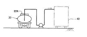
上記(i)のガソリンベーパーの放出量は、地下タンクへのガソリン受け入れ相当量となる。(i)のガソリンベーパーを回収する方法としては、図3及び図4に示すような押し出されたガソリンベーパーをタンクローリー30に戻す方法(ステージ1と称される方法)がある。すなわち、タンクローリー30からガソリンを地下タンク36に受け入れる際、通気管33とタンクローリーのタンク34を接続し、タンクローリー30からガソリンを地下タンク36に受け入れる際に押し出されたガソリンベーパーを接続配管35を通してタンクローリー30に回収する一方、回収したガソリンベーパーを持ち帰り、油槽所等の回収装置40で回収する方法である。しかし、この方法は大都市が中心であり全国的に実施されているとは言い難い。またタンクローリー30に戻したガソリンベーパーを回収する設備が別途必要となるという問題がある。
The amount of gasoline vapor released in (i) above is equivalent to the amount of gasoline accepted into the underground tank. As a method for recovering the gasoline vapor (i), there is a method for returning the extruded gasoline vapor to the
上記(ii)のガソリンベーパーを回収する方法としては、2重管の給油管を用い、発生するガソリンベーパーを外装管と内装管で形成される隙間を通して真空ポンプで吸引して地下タンクに戻す方法(ステージ2と称される方法)がある。しかし、この方法は給油ガソリン以上にガソリンを吸引するために地下タンクから過剰分が放出されるという問題がある。因みに石油活性化センター報告書(M4.1.1)はステージ2の場合、給油1ガロン当り0.3〜1.0gTHCを排出すると報告している。
As a method for recovering the gasoline vapor of (ii) above, a method of using a double oil supply pipe and sucking the generated gasoline vapor through a gap formed by the outer pipe and the inner pipe with a vacuum pump and returning it to the underground tank (Method called stage 2). However, this method has a problem that an excess amount is discharged from the underground tank in order to suck gasoline more than refueling gasoline. The oil activation center report (M4.1.1) reports that in the case of
また、上記(iii)のガソリンベーパーの発生機構は次ぎの通りである。すなわち、給油時には給油分のガソリンに見合った空気が地下タンク内に流入する。この時、地下タンク内の気相のガソリン濃度は希釈される。ガソリンは飽和濃度まで蒸発するため地下タンク内の気相の容量は増加し、増加分は地下タンクから通気管を通って外へ放出される。因みに飽和濃度が25%の場合、計算によれば給油量の40%に相当する気体がタンクから放出される。 The generation mechanism of the gasoline vapor (iii) is as follows. That is, at the time of refueling, air commensurate with the refueling gasoline flows into the underground tank. At this time, the gasoline concentration in the gas phase in the underground tank is diluted. Gasoline evaporates to a saturated concentration, so the gas phase capacity in the underground tank increases, and the increase is released from the underground tank through the vent pipe. Incidentally, when the saturation concentration is 25%, according to the calculation, a gas corresponding to 40% of the oil supply amount is released from the tank.
上記(ii)のガソリンベーパーを回収する方法は少数であるため、結局地下タンクの通気管から放出されるガソリンベーパーを小型の装置で効率よく回収することが急務となっている。現在この問題を解決するものとしては、ドイツGKSS等が開発した膜を使ったSS向けガソリンベーパー回収システム「パーミエーター」がある。この回収システムは高分子膜を利用したものであり、膜の一方の側にガソリンベーパーを含む排ガスを通し、他方の側を真空ポンプで吸引して真空としてガソリンベーパーを浸透させて回収する方法である。このSS向けガソリンベーパー回収システムは、ガソリンスタンドの領域内という限られたスペース内に設置できる小型の回収装置を使用するため都合がよい。
しかしながら、高分子膜によりガソリンベーパーを回収する方法は、ガソリンベーパーの回収率がせいぜい90%であり、必ずしも満足するものではない。一方、従来より油槽所などで使用されている揮発性炭化水素化合物含有排ガスを2塔式圧力スイング吸着装置で回収する方法(例えば特許第2766793号公報)によれば、揮発性炭化水素化合物を回収率99%以上で回収することができる。しかし、従来の2塔式圧力スイング吸着装置は、揮発性炭化水素化合物含有排ガスの処理能力が大きいため、真空ポンプ出口に冷却凝縮器を設定している。また、2塔式圧力スイング吸着装置の開閉弁は、制御盤の防爆式電磁弁で制御される開閉弁を使用しているなどそのままSS向けガソリンベーパー回収システムに適用するには設置コストを上昇させるなどの問題があった。 However, the method of recovering gasoline vapor using a polymer membrane is not always satisfactory because the recovery rate of gasoline vapor is 90% at most. On the other hand, according to a method (for example, Japanese Patent No. 2766793) of recovering exhaust gas containing volatile hydrocarbon compounds conventionally used in oil tanks or the like with a two-column pressure swing adsorption device, recover volatile hydrocarbon compounds. It can be recovered at a rate of 99% or more. However, since the conventional two-column pressure swing adsorption apparatus has a large processing capacity for exhaust gas containing volatile hydrocarbon compounds, a cooling condenser is set at the outlet of the vacuum pump. In addition, the opening / closing valve of the two-column pressure swing adsorption device uses an opening / closing valve controlled by an explosion-proof electromagnetic valve on the control panel. There were problems such as.
従って、本発明の目的は、設置コストが低減された小型の2塔式圧力スイング吸着装置を使用してSSの地下タンクから発生するガソリンベーパーを99%以上の回収率で回収する方法及びその回収装置を提供することにある。 Therefore, an object of the present invention is to recover a gasoline vapor generated from an SS underground tank at a recovery rate of 99% or more using a small two-column pressure swing adsorption device with reduced installation cost, and the recovery thereof. To provide an apparatus.
かかる実情において、本発明者らは鋭意検討を行った結果、回収装置は概ね40m3/時の排出ガス処理能力を持ち、且つ脱着性能に優れた特定の吸着剤を使用した小型2塔式圧力スイング吸着装置であれば、該装置の真空ポンプ出口に冷却凝縮器を設置することなくコストを低減できること、また、該装置とガソリンスタンド事務所の距離が近いため、ガソリンスタンド事務所内に制御盤が設置でき、安価な非防爆式電磁弁が使用でき、更に回収装置の開閉弁を安価な空気式にできることなどを見出し、本発明を完成するに至った。
Under such circumstances, the present inventors have conducted extensive studies, and as a result, the recovery device has a small adsorbent with a specific adsorbent having an exhaust gas treatment capacity of approximately 40
すなわち、本発明(1)は、ガソリンスタンドの地下タンクから放出されるガソリンベーパー含有排ガスを2塔式圧力スイング吸着装置で回収する方法であって、吸着工程の吸着装置にガソリンベーパー含有排ガスを導入して、細孔径3〜20nmの活性炭及び細孔径6〜10nmのシリカゲルが混層充填又は2層充填されている吸着剤にガソリンベーパーを吸着させ、清浄化した廃棄ガスを大気に放出し、再生工程の吸着装置の吸着剤に吸着したガソリンベーパーを真空ポンプで吸引して該吸着剤から離脱したガソリンベーパーを冷却凝縮器を通さずに該地下タンクに回収することを特徴とするガソリンベーパーの回収方法を提供するものである。 That is, the present invention (1) is a method for recovering gasoline vapor-containing exhaust gas discharged from an underground tank of a gas station with a two-column pressure swing adsorption device, and introducing the gasoline vapor-containing exhaust gas into the adsorption device of the adsorption process. Then, the gasoline vapor is adsorbed to the adsorbent in which the activated carbon having the pore diameter of 3 to 20 nm and the silica gel having the pore diameter of 6 to 10 nm is mixed or filled with the two layers, and the purified waste gas is released to the atmosphere, and the regeneration process A method for recovering gasoline vapor, characterized in that the gasoline vapor adsorbed on the adsorbent of the adsorbing apparatus is sucked with a vacuum pump and the gasoline vapor separated from the adsorbent is recovered in the underground tank without passing through a cooling condenser Is to provide.
また、本発明(2)は、前記回収するガソリンベーパーは、前記地下タンクの通気管から放出されるガソリンベーパーであることを特徴とする請求項1記載のガソリンベーパーの回収方法を提供するものである。 Further, the present invention (2) is, gasoline vapor to the recovery, which provides a method for recovering gasoline vapor of claim 1 Symbol mounting, characterized in that a gasoline vapor released from the vent tube of the underground tanks It is.
また、本発明(3)は、前記通気管の大気放出弁の地下タンク側の圧力が所定の圧力(p1Pa)以上で2塔式圧力スイング吸着装置の運転を開始し、前記圧力(p1Pa)より低い所定の圧力(p2Pa)以下で運転を停止することを特徴とする請求項2記載のガソリンベーパーの回収方法を提供するものである。
Further, the present invention ( 3 ) starts the operation of the two-column pressure swing adsorption device when the pressure on the underground tank side of the air discharge valve of the vent pipe is equal to or higher than a predetermined pressure (p 1 Pa), and the pressure (p The method for recovering gasoline vapor according to
また、本発明(4)は、大気放出弁の地下タンク側に圧力検知器を付設した地下タンクの通気管と、ガソリンスタンドの敷地内に設置される2塔式圧力スイング吸着装置と、該2塔式圧力スイング吸着装置の再生工程にある吸着装置の細孔径3〜20nmの活性炭及び細孔径6〜10nmのシリカゲルが混層充填又は2層充填されている吸着剤に吸着したガソリンベーパーを吸引する真空ポンプと、該通気管の大気放出弁の地下タンク側の配管部と該2塔式圧力スイング吸着装置を接続する第1配管と、該真空ポンプと該地下タンクを接続する第2配管を備えるものであって、該第2配管には冷却凝縮器を設置しないことを特徴とするガソリンベーパーの回収装置を提供するものである。
Further, the present invention ( 4 ) includes an underground tank vent pipe provided with a pressure detector on the underground tank side of the atmospheric release valve, a two-column pressure swing adsorption device installed in a gas station site, vacuum sucking the gasoline vapor which silica gel activated carbon and pore diameter 6~10nm of
また、本発明(5)は、前記2塔式圧力スイング吸着装置の開閉弁が、ガソリンスタンド事務所内に設置された制御盤の非防爆式電磁弁で制御される空気信号で制御される空気式開閉弁であることを特徴とする請求項4記載のガソリンベーパーの回収装置を提供するものである。
Further, according to the present invention ( 5 ), the open / close valve of the two-column pressure swing adsorption device is controlled by an air signal controlled by a non-explosion-proof electromagnetic valve of a control panel installed in a gas station office. 5. A gasoline vapor recovery device according to
本発明のガソリンベーパーの回収方法によれば、脱着性能に優れた特定の吸着剤を使用した小型2塔式圧力スイング吸着装置を使用するため、該装置の真空ポンプ出口に冷却凝縮器を設置することなくコストを低減できると共に、回収率99%以上を達成できる。また、該装置とガソリンスタンド事務所の距離が近いため、ガソリンスタンド事務所内に制御盤が設置でき、安価な非防爆式電磁弁が使用できる。 According to the method for recovering gasoline vapor of the present invention, since a small two-column pressure swing adsorption device using a specific adsorbent having excellent desorption performance is used, a cooling condenser is installed at the vacuum pump outlet of the device. The cost can be reduced and a recovery rate of 99% or more can be achieved. Moreover, since the distance between the apparatus and the gas station office is short, a control panel can be installed in the gas station office, and an inexpensive non-explosion-proof solenoid valve can be used.
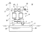
本発明の実施の形態におけるガソリンベーパーの回収方法を図1を参照して説明する。図1は本例のガソリンベーパーの回収方法を実施する回収装置の簡略図である。図1のガソリンベーパー回収装置10は、大気放出弁4の1次側に圧力検知器5を付設した地下タンクの通気管3と、ガソリンスタンドの敷地内に設置される2塔式圧力スイング吸着装置9と、2塔式圧力スイング吸着装置9の再生工程にある吸着装置1a(1b)の吸着剤に吸着したガソリンベーパーを吸引する真空ポンプ7と、通気管3の大気放出弁4の1次側の配管部32と2塔式圧力スイング吸着装置9を接続する第1配管31と、真空ポンプ7と地下タンク2を接続する第2配管71とを備える。ガソリンベーパー回収装置10においては従来、油槽所等で使用されていた2塔式圧力スイング吸着装置では真空ポンプの出口側に設置する必須の機器である冷却凝縮器は設置されていない。なお、符号25は地下タンク内の気相部であり、26は液状ガソリン部である。
A method for recovering gasoline vapor in the embodiment of the present invention will be described with reference to FIG. FIG. 1 is a simplified diagram of a recovery apparatus for carrying out the gasoline vapor recovery method of this example. A gasoline
2塔式圧力スイング吸着装置9は、並列配置された2つの吸着塔1a、1bと、吸着塔1a、1bの吸着工程における入口側開閉弁a、bと、出口側開閉弁g、hと、吸着塔1a、1bの再生工程における入口側開閉弁e、fと、出口側開閉弁c、dとを備え、開閉弁a、bを接続する配管には第1配管31(ガソリンベーパー含有排ガス供給管)の一端が接続され、開閉弁c、dを接続する配管には真空ポンプ入口配管72の一端が接続され、開閉弁e、fを接続する配管には清浄ガス排出管82から分岐した制御弁6を備えるパージガス供給管81の一端が接続され、開閉弁g、hを接続する配管には清浄ガスを大気へ放出する清浄ガス排出管82の一端が接続されている。なお、開閉弁a〜hは図1に示されるものに限定されず、開閉弁a、b、開閉弁c、d、開閉弁e、f、開閉弁g、hにおいてそれぞれ1つの三方弁としてもよい。
The two-column pressure
2塔式圧力スイング吸着装置9は、タンクローリーから地下タンク(実容量20kl)への送油が30分程度で終了することから40m3/時間程度の処理能力を有していればよい。また、2塔式圧力スイング吸着装置9には、不図示の制御部により前記通気管の大気放出弁の1次側の圧力が所定の圧力(p1Pa)以上で2塔式圧力スイング吸着装置9の運転を開始し、前記圧力(p1Pa)より低い所定の圧力(p2Pa)以下で運転を停止するようになっている。p1としては、例えば400Paであり、p2としては、例えば100Paである。
The two-column pressure
吸着塔1a、1bに充填される吸着剤としては、細孔径3〜20nmの活性炭又は細孔径6〜10nmのシリカゲルが挙げられる。これらの吸着剤は吸着能のみならず脱着能も優れることから、後述するように真空ポンプ出口の冷却凝縮器の設置を省略することができる。細孔径が3nm未満の活性炭の場合、吸着能は優れるものの発熱量が多く、またこのようなミクロの細孔内に入ったガソリンベーパーの脱着は例え真空ポンプとパージガスを併用する方法であっても真空度を高めなければ再生が困難な場合がある。これら活性炭及びシリカゲルは単独又は併用することができる。単独使用の場合、細孔径3〜20nmの活性炭を用いることが好ましい。例えば1.2%のn-ヘプタンの平衡吸着量は活性炭が0.5g/gであるのに対して、シリカゲルが0.05g/gであり、活性炭の方が吸着能力が高く装置をコンパクト化できるためである。
Examples of the adsorbent filled in the
また、吸着剤は、細孔径3〜20nmの活性炭及び細孔径6〜10nmのシリカゲルを併用すれば、例えば活性炭単独使用の場合に問題となる吸着熱による発熱の問題を回避することができる。該活性炭とシリカゲルの併用形態(充填形態)としては、特に制限されないが、例えば吸着剤の充填は、細孔径3〜20nmの活性炭又は細孔径6〜10nmのシリカゲル混層充填、又は原ガス側から順に細孔径6〜10nmのシリカゲル及び細孔径3〜20nmの活性炭とする2層充填された充填形態が挙げられる。該混層充填とは、活性炭とシリカゲルが任意の割合で混合され充填される形態を言う。 Further, when the adsorbent is used in combination with activated carbon having a pore diameter of 3 to 20 nm and silica gel having a pore diameter of 6 to 10 nm, for example, the problem of heat generation due to heat of adsorption that becomes a problem when using activated carbon alone can be avoided. Although it does not restrict | limit especially as a combined form (packing form) of this activated carbon and a silica gel, For example, the filling of an adsorbent is the activated carbon with a pore diameter of 3-20 nm, the silica gel mixed layer filling with a pore diameter of 6-10 nm, or a raw gas side in order. A two-layer packed form of silica gel having a pore diameter of 6 to 10 nm and activated carbon having a pore diameter of 3 to 20 nm may be mentioned. The mixed layer filling refers to a form in which activated carbon and silica gel are mixed and filled in an arbitrary ratio.
真空ポンプ7としては、特に制限されず、例えばドライ型真空ポンプ又はオイル型真空ポンプが挙げられる。本例の回収装置10の場合、安価なオイル型真空ポンプであっても使用できる。オイル型真空ポンプを用いる場合、真空ポンプ内蔵フィルターを使用することが、回収ガソリンの性状に影響を与えることなく、排気ガス中のオイルを99%以上回収することができる点で好適である。
The
本例のガソリンベーパー回収装置10は、真空ポンプ7と地下タンク2を接続する第2配管71に冷却凝縮器が設置されていないものである。冷却凝縮器の設置を省略できる理由としては、真空ポンプ7の処理風量が少ない点及び再生条件が50torr(絶対圧6.6kPa)で再生できる上記の脱着性能に優れた吸着剤を採用した点にある。従来の油槽所などで使用される2塔式圧力スイング吸着装置における真空ポンプの出口温度は、25torr(絶対圧3.3kPa)の再生圧力で120〜140℃であるが、本例の回収装置では上記50torrの再生圧力で50〜100℃である。このため、真空ポンプ排出ガスと地下タンク及び貯蔵ガソリンとの温度差が小さくなる。また地下タンク、貯蔵ガソリンの持っている熱容量に対して真空ポンプ排出ガスの熱容量も小さいので、新たにガソリンを蒸発させることは殆どない。
In the gasoline
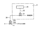
開閉弁a〜hとしては、ガソリンスタンド事務所内に設置された制御盤の非防爆式電磁弁で制御される空気信号で制御される空気式開閉弁を使用することができる。ガソリンスタンド事務所は、非危険場所の総称であって、ガソリンスタンド領域内にある事務所の他、事務所ではない屋外の建屋等が含まれる。空気式開閉弁の作動機構を図2を参照して説明する。図2は2塔式圧力スイング吸着装置9の空気式開閉弁aの開閉をガソリンスタンド事務所内に設置された制御盤Xの非防爆式電磁弁21で制御するようにしたものである。符号22はシーケンサー、23は電気信号、24は空気信号(空気流路)、251は圧縮空気、252はバネである。
As the on / off valves a to h, air on / off valves controlled by an air signal controlled by a non-explosion-proof electromagnetic valve of a control panel installed in a gas station office can be used. The gas station office is a general term for non-hazardous areas, and includes an office in the gas station area and an outdoor building that is not an office. The operation mechanism of the pneumatic on-off valve will be described with reference to FIG. In FIG. 2, the opening and closing of the pneumatic on-off valve a of the two-column pressure
空気式開閉弁aは空気で作動するもので、具体的には空気を供給して空気圧を発生させ、該空気圧とバネ力のバランスで開閉を行なうものである。従来の2塔式圧力スイング吸着装置9の開閉弁としては、伝達の遅れがない電気信号で開閉する電磁弁などの電気式開閉弁が使用されていた。本例の2塔式圧力スイング吸着装置9の開閉弁は、空気式開閉弁を使用してもガソリンスタンド事務所内に設置された電磁弁21と空気式開閉弁aの距離が近く、一般的に知られている圧縮空気の伝達の遅れの問題はない。また、電磁弁21はガソリンスタンド事務所内に設置できるため、高価な防爆式電磁弁を使用する必要がない。
The pneumatic on-off valve a is operated by air. Specifically, air is supplied to generate air pressure, and the air on / off valve a is opened and closed with a balance between the air pressure and the spring force. As an on-off valve of the conventional two-column pressure
また、本例のガソリンベーパー回収装置10の計装方法としては、非防爆式の制御盤をガソリンスタンド事務所に設置し、該制御盤に電源装置、シーケンサー及び非防爆式電磁弁を組み込み、非防爆式電磁弁で制御される空気信号で回収装置のスキッド内の空気開閉弁を制御する計装方法が挙げられる。本例のガソリンベーパー回収装置10の計装方法によれば、コストの高い防爆式電磁弁の採用を避けることができる。また、ガソリンスタンド事務所と回収装置のスキッド間の距離はせいぜい20〜30mと近距離であり、信号の時間遅れの問題を生じることはない。なお、スキッドとは、例えばH鋼で作製されたベース上に回収装置が設置された一体化物を言い、装置のスキッド化は搬送がし易く、現地での組み立て工事が容易となる。
Further, as an instrumentation method of the gasoline
本例の2塔式圧力スイング吸着装置を用いたPSA法は公知の方法であり、例えば2つの吸着塔がそれぞれ係り合い不図示の弁シーケンスに従って、吸着(運転)/再生の繰り返し工程を実施するものである。
本実施の形態例におけるPSA法において、吸着工程は次ぎのとおりである。例えばタンクローリーからガソリンを地下タンクに受け入れる際に押し出されたガソリンベーパーは通気管を流通する。この際、通気管の大気放出弁の1次側の圧力が所定の圧力(p1Pa)以上となると、ガソリンベーパー含有排ガスは吸着ステップにある吸着塔1aの吸着剤層入り口端部へ導入される。排ガス中のガソリンベーパーは吸着剤層の入口側から徐々に吸着され、吸着塔1aの頂部の清浄ガス排出管82からガソリンベーパーを除去された清浄ガスが排出される。一方ガソリンベーパーの吸着量が限界に達した吸着塔1aは次ぎの再生工程へ進む。再生工程の吸着塔1aの吸着剤に吸着したガソリンベーパーを真空ポンプ7で吸引して該吸着剤から離脱したガソリンベーパーをそのまま該地下タンク2に回収する。再生工程においては、真空ポンプ7の吸引に加えてパージガスを併用すれば吸着剤の再生の程度が向上する。
The PSA method using the two-column pressure swing adsorption device of this example is a known method. For example, two adsorption towers are engaged with each other, and an adsorption (operation) / regeneration process is repeated according to a valve sequence (not shown). Is.
In the PSA method in the present embodiment, the adsorption process is as follows. For example, a gasoline vapor pushed out from a tank lorry when receiving gasoline into an underground tank circulates through a ventilation pipe. At this time, when the pressure on the primary side of the air release valve of the vent pipe becomes equal to or higher than a predetermined pressure (p1 Pa), the gasoline vapor-containing exhaust gas is introduced into the adsorbent layer inlet end of the adsorption tower 1a in the adsorption step. The gasoline vapor in the exhaust gas is gradually adsorbed from the inlet side of the adsorbent layer, and the clean gas from which the gasoline vapor has been removed is discharged from the clean
真空ポンプ7の吸引条件としては、5.3kPa〜9.3kPa、好ましくは6.7kPa〜8.0kPaである。本例の回収方法は真空ポンプ7の処理風量が少なく、且つ脱着性能に優れた吸着剤を採用したことから、従来の大型2塔式圧力スイング吸着装置における真空ポンプの吸引条件よりも緩やかな真空条件で再生することができる。上記吸引条件(真空度)において、真空ポンプ7の出口温度は50〜100℃とすることができる。このため、真空ポンプ排出ガスと地下タンク及び貯蔵ガソリンとの温度差が小さくなる。また地下タンク、貯蔵ガソリンの持っている熱容量に対して真空ポンプ排出ガスの熱容量も小さいので、新たにガソリンを蒸発させることは殆どない。
The suction conditions of the
2塔式圧力スイング吸着装置の2つの吸着塔が上記の吸着工程/再生工程を行う際、切り替え間隔時間としては、一概には決定できないが、通常3〜10分程度である。以下、上記吸着塔1aの吸着工程は、他の吸着塔1bに対しても繰り返し実施される。なお、図1の吸着工程/再生工程における開閉弁の状態を表1に示す。地下タンク2から通気管3に押し出されるガソリンベーパーが少なくなると通気管3内の圧力は低下し、通気管3の大気放出弁4の1次側の圧力(配管32内の圧力)が前記運転圧力(p1Pa)より低い所定の圧力(p2Pa)以下になると、2塔式圧力スイング吸着装置9の運転は停止する。
When the two adsorption towers of the two-column pressure swing adsorption apparatus perform the above-described adsorption process / regeneration process, the switching interval time cannot be generally determined, but is usually about 3 to 10 minutes. Hereinafter, the adsorption process of the adsorption tower 1a is repeatedly performed on the

本例のガソリンベーパーの回収方法によれば、脱着性能に優れた特定の吸着剤を使用した小型2塔式圧力スイング吸着装置を使用するため、該装置の真空ポンプ出口に冷却凝縮器を設定することなく設置コストを低減できると共に、ガソリンベーパー回収率99%以上を達成できる。また、該装置とガソリンスタンド事務所の距離が近いため、ガソリンスタンド事務所内に制御盤が設置でき、安価な非防爆式電磁弁が使用できる。 According to the method for recovering gasoline vapor of this example, since a small two-column pressure swing adsorption device using a specific adsorbent excellent in desorption performance is used, a cooling condenser is set at the vacuum pump outlet of the device. The installation cost can be reduced without any problem, and a gasoline vapor recovery rate of 99% or more can be achieved. Further, since the distance between the apparatus and the gas station office is short, a control panel can be installed in the gas station office, and an inexpensive non-explosion-proof solenoid valve can be used.
次に実施例を挙げて本発明を更に具体的に説明するが、これは単に例示であって、本発明を制限するものではない。 EXAMPLES Next, although an Example is given and this invention is demonstrated more concretely, this is only an illustration and does not restrict | limit this invention.
図1に示すガソリンベーパー回収装置10を使用し、下記運転条件でガソリンベーパーの回収を行なった。その結果、清浄排ガスのガソリン濃度は1000ppm以下で且つガソリンベーパーを回収率99%以上で回収することができた。
・ガソリンベーパー含有排ガス;タンクローリーから実容量20klの地下タンクにガソリンを30分で送油する際、通気管より発生する排ガス
・ 2塔式圧力スイング吸着装置の処理能力;40m3/時間
・ 通気管設置の大気放出弁;372Paで排気/−125Paで吸気
・ 装置の起動/停止;350Paで起動/100Paで停止
・ 吸着剤;原ガス側より細孔径6nmのシリカゲルと細孔径5nmの活性炭の2層充填
・ 吸着工程/再生工程;5分間隔で交互の切り替え運転
・ 再生工程;パージガス導入と真空ポンプの併用による
・ 真空ポンプ;オイル型(吸引圧力;50torr、出口温度80℃)
Using the gasoline
-Gasoline vapor-containing exhaust gas; Exhaust gas generated from a vent pipe when gasoline is sent from a tank lorry to an underground tank with an actual capacity of 20 kl in 30 minutes-Processing capacity of a two-column pressure swing adsorption device; 40 m3 / hr Air release valve: 372 Pa exhaust / -125 Pa intake / device start / stop; 350 Pa start / stop 100 Pa / adsorbent; 2 layers of silica gel with 6 nm pore diameter and activated carbon with 5 nm pore diameter from the raw gas side・ Adsorption process / regeneration process; alternate switching operation every 5 minutes ・ Regeneration process; combined use of purge gas and vacuum pump ・ Vacuum pump; oil type (suction pressure: 50 torr, outlet temperature 80 ° C)
1a、1b 吸着塔
2、36 地下タンク
3、33 通気管
4 大気放出弁
5 圧力検知器
6 制御弁
7 真空ポンプ
9 2塔式圧力スイング吸着装置
10 ガソリンベーパー回収装置
21 非防爆式電磁弁
22 シーケンサー
23 電気信号
24 空気信号
25 地下タンクの気相部
26 地下タンクの液状ガソリン部
30 タンクローリー
31 第1配管
34 タンクローリーのタンク
35 接続配管
40 回収装置
71 第2配管
81 パージガス供給管
82 清浄ガス排出管
a〜h 開閉弁
DESCRIPTION OF
71
Claims (5)
Priority Applications (1)
| Application Number | Priority Date | Filing Date | Title |
|---|---|---|---|
| JP2004010384A JP4575673B2 (en) | 2004-01-19 | 2004-01-19 | Gasoline vapor recovery method and recovery device |
Applications Claiming Priority (1)
| Application Number | Priority Date | Filing Date | Title |
|---|---|---|---|
| JP2004010384A JP4575673B2 (en) | 2004-01-19 | 2004-01-19 | Gasoline vapor recovery method and recovery device |
Publications (2)
| Publication Number | Publication Date |
|---|---|
| JP2005199223A JP2005199223A (en) | 2005-07-28 |
| JP4575673B2 true JP4575673B2 (en) | 2010-11-04 |
Family
ID=34823121
Family Applications (1)
| Application Number | Title | Priority Date | Filing Date |
|---|---|---|---|
| JP2004010384A Expired - Fee Related JP4575673B2 (en) | 2004-01-19 | 2004-01-19 | Gasoline vapor recovery method and recovery device |
Country Status (1)
| Country | Link |
|---|---|
| JP (1) | JP4575673B2 (en) |
Families Citing this family (11)
| Publication number | Priority date | Publication date | Assignee | Title |
|---|---|---|---|---|
| JP4658888B2 (en) * | 2006-09-25 | 2011-03-23 | Jfeエンジニアリング株式会社 | Vapor collection device and vapor collection method |
| JP5123541B2 (en) * | 2007-03-23 | 2013-01-23 | トキコテクノ株式会社 | Vapor collection device |
| JP5060159B2 (en) * | 2007-04-24 | 2012-10-31 | トキコテクノ株式会社 | Vapor collection device |
| JP2011021505A (en) | 2009-07-14 | 2011-02-03 | Aisan Industry Co Ltd | Evaporated fuel processing device |
| JP5582810B2 (en) * | 2010-02-12 | 2014-09-03 | トキコテクノ株式会社 | Vapor collection system |
| CN109772088A (en) * | 2019-03-05 | 2019-05-21 | 江苏鼎程新能源科技有限公司 | A kind of gas station device for recovering oil and gas three times |
| CN110585851A (en) * | 2019-10-25 | 2019-12-20 | 青岛诺诚化学品安全科技有限公司 | Filling station's cubic vapor recovery system device |
| CN113307217A (en) * | 2021-04-15 | 2021-08-27 | 北京北控工业环保科技有限公司 | Three-time oil gas recovery system and process for gas station |
| CN114100307A (en) * | 2021-06-10 | 2022-03-01 | 武汉三江航天远方科技有限公司 | Filling station's cubic oil gas recovery system |
| CN114354235B (en) * | 2022-01-13 | 2024-05-07 | 日照惠明机械设备有限公司 | Three-time oil gas recovery test bench and test method |
| CN120045817B (en) * | 2025-04-23 | 2025-07-18 | 生态环境部华南环境科学研究所(生态环境部生态环境应急研究所) | A method for correcting VOCs emissions during the breathing process of a gas station based on an oil vapor recovery vacuum pump type |
Family Cites Families (4)
| Publication number | Priority date | Publication date | Assignee | Title |
|---|---|---|---|---|
| JPS5048515A (en) * | 1973-09-03 | 1975-04-30 | ||
| DE4410597C2 (en) * | 1994-03-26 | 1999-07-22 | Geesthacht Gkss Forschung | Method and device for reducing emissions from breathing lines in storage tanks |
| JP2766793B2 (en) * | 1995-08-29 | 1998-06-18 | システム エンジ サービス株式会社 | Treatment and recovery of gaseous hydrocarbons contained in waste gas |
| JPH1199314A (en) * | 1997-09-26 | 1999-04-13 | Cosmo Engineering Co Ltd | Operation of hydrocarbon vapor recovery |
-
2004
- 2004-01-19 JP JP2004010384A patent/JP4575673B2/en not_active Expired - Fee Related
Also Published As
| Publication number | Publication date |
|---|---|
| JP2005199223A (en) | 2005-07-28 |
Similar Documents
| Publication | Publication Date | Title |
|---|---|---|
| JP4575673B2 (en) | Gasoline vapor recovery method and recovery device | |
| CN103754814B (en) | Fuel Vapor Management System with Proportional Split | |
| WO1997020618A1 (en) | Method of treating or recovering gaseous hydrocarbon contained in waste gas | |
| CN201350385Y (en) | Adsorption and recovery processing device of volatile organic steam | |
| CN102921269A (en) | Oil gas recycling device | |
| JP4001957B2 (en) | Fuel transpiration prevention device | |
| JP5109028B2 (en) | Method for purifying a large amount of exhaust gas containing lean volatile hydrocarbons | |
| CN110585851A (en) | Filling station's cubic vapor recovery system device | |
| CN215782595U (en) | Hollow fiber tubular membrane oil gas treatment system with washing absorption tower | |
| CN111437622A (en) | Oil and gas processing system and method | |
| CN213668552U (en) | Compression condensation film adsorption combined type oil gas recovery device | |
| CN211936242U (en) | Tertiary oil gas recovery unit of filling station | |
| JP2000117048A (en) | Adsorption type collection device and adsorption recovery device for volatile petroleum compounds | |
| CN212700620U (en) | Oil and gas treatment system | |
| CN101015760A (en) | Oil-gas recovery method and device using absorption and adsorbing integration technology | |
| CN105833657A (en) | Alcohol mixture tail gas treatment device and method | |
| CN204865444U (en) | Meticulous processing system in vapor recovery system rear end | |
| CN110711460A (en) | Oil and gas recovery system and recovery method | |
| KR20210026077A (en) | Oil gas recovery system | |
| WO1996004978A1 (en) | Pressure swing adsorption apparatus and process for recovery of organic vapors | |
| CN216909746U (en) | Hollow fiber tubular membrane oil gas treatment system with condenser | |
| CA2021702A1 (en) | Improved process for recovering hydrocarbons from air-hydrocarbon vapor mixtures | |
| CN211159155U (en) | Filling station's cubic vapor recovery system device | |
| CN211585903U (en) | Oil and gas recovery system | |
| JP2005205392A (en) | Treating method of exhaust gas containing volatile hydrocarbon |
Legal Events
| Date | Code | Title | Description |
|---|---|---|---|
| A621 | Written request for application examination |
Free format text: JAPANESE INTERMEDIATE CODE: A621 Effective date: 20061227 |
|
| A977 | Report on retrieval |
Free format text: JAPANESE INTERMEDIATE CODE: A971007 Effective date: 20091130 |
|
| A131 | Notification of reasons for refusal |
Free format text: JAPANESE INTERMEDIATE CODE: A131 Effective date: 20091210 |
|
| A521 | Request for written amendment filed |
Free format text: JAPANESE INTERMEDIATE CODE: A523 Effective date: 20100107 |
|
| A131 | Notification of reasons for refusal |
Free format text: JAPANESE INTERMEDIATE CODE: A131 Effective date: 20100512 |
|
| A521 | Request for written amendment filed |
Free format text: JAPANESE INTERMEDIATE CODE: A523 Effective date: 20100628 |
|
| TRDD | Decision of grant or rejection written | ||
| A01 | Written decision to grant a patent or to grant a registration (utility model) |
Free format text: JAPANESE INTERMEDIATE CODE: A01 Effective date: 20100810 |
|
| A01 | Written decision to grant a patent or to grant a registration (utility model) |
Free format text: JAPANESE INTERMEDIATE CODE: A01 |
|
| A61 | First payment of annual fees (during grant procedure) |
Free format text: JAPANESE INTERMEDIATE CODE: A61 Effective date: 20100820 |
|
| R150 | Certificate of patent or registration of utility model |
Ref document number: 4575673 Country of ref document: JP Free format text: JAPANESE INTERMEDIATE CODE: R150 |
|
| FPAY | Renewal fee payment (event date is renewal date of database) |
Free format text: PAYMENT UNTIL: 20130827 Year of fee payment: 3 |
|
| R250 | Receipt of annual fees |
Free format text: JAPANESE INTERMEDIATE CODE: R250 |
|
| R250 | Receipt of annual fees |
Free format text: JAPANESE INTERMEDIATE CODE: R250 |
|
| R250 | Receipt of annual fees |
Free format text: JAPANESE INTERMEDIATE CODE: R250 |
|
| R250 | Receipt of annual fees |
Free format text: JAPANESE INTERMEDIATE CODE: R250 |
|
| R250 | Receipt of annual fees |
Free format text: JAPANESE INTERMEDIATE CODE: R250 |
|
| R250 | Receipt of annual fees |
Free format text: JAPANESE INTERMEDIATE CODE: R250 |
|
| R250 | Receipt of annual fees |
Free format text: JAPANESE INTERMEDIATE CODE: R250 |
|
| R250 | Receipt of annual fees |
Free format text: JAPANESE INTERMEDIATE CODE: R250 |
|
| R250 | Receipt of annual fees |
Free format text: JAPANESE INTERMEDIATE CODE: R250 |
|
| R250 | Receipt of annual fees |
Free format text: JAPANESE INTERMEDIATE CODE: R250 |
|
| LAPS | Cancellation because of no payment of annual fees |