JP4570838B2 - Method of forming a cap part of a bottle can body and screw forming apparatus - Google Patents
Method of forming a cap part of a bottle can body and screw forming apparatus Download PDFInfo
- Publication number
- JP4570838B2 JP4570838B2 JP2002233917A JP2002233917A JP4570838B2 JP 4570838 B2 JP4570838 B2 JP 4570838B2 JP 2002233917 A JP2002233917 A JP 2002233917A JP 2002233917 A JP2002233917 A JP 2002233917A JP 4570838 B2 JP4570838 B2 JP 4570838B2
- Authority
- JP
- Japan
- Prior art keywords
- screw
- bottle
- thread
- forming
- stage
- Prior art date
- Legal status (The legal status is an assumption and is not a legal conclusion. Google has not performed a legal analysis and makes no representation as to the accuracy of the status listed.)
- Expired - Lifetime
Links
Images


Landscapes
- Containers Having Bodies Formed In One Piece (AREA)
- Closures For Containers (AREA)
Description
【0001】
【発明の属する技術分野】
この発明は、ボトル缶体の口金部にキャップを被着するためにねじ部を形成する口金部成形方法と、そのねじ成形装置に関する。
【0002】
【従来の技術】
金属製の缶体を絞り加工して得られる、いわゆるボトル缶体は、有底筒状に形成されたボトル缶体の開口部に口金部を形成し、その口金部の外周にキャップを被着するためのねじ部を形成する。
【0003】
このようなねじ部を有するボトル缶体を制作するには、予め有底円筒状のボトル缶体が形成されると、そのボトル缶体の開口部を、図8(a)に示すように、一旦縮径して口金部2を形成し、次いで、その口金部2の開口端から所定距離分だけ拡径して同図(b)に示すように拡径部2′を形成した後、さらにねじ成形装置によって開口端から一定の距離に同図(c)のようにねじ部3を形成する。
その場合、口金部2にねじ部3を形成したとき、ねじ部3の形成されていない拡径部分を残すことにより、膨出部4が形成される。
【0004】
従来のねじ成形装置は、図示していないが、口金部2の内周面に当接する中子と、口金部2の外周面に当接する外子とが互いに口金部2を挟み込みながらボトル缶体1の軸心周りに回転することで、口金部2の外周にねじ部3を形成するようになっている。この場合、口金部2に形成されるねじ部3の巻数としては、図9に示すようにおよそ1.7巻程度となっている。
【0005】
また、ねじ部3が形成されたボトル缶体1は、その後、口金部2の先端を外側から内側に折り折り返し、図9に示すようにカール部8を形成するカールかしめ工程を行う等の種々の工程を経た後、内部に内容物が入れられると、同図に示すキャップ5が被着されて閉栓される。
【0006】
【発明が解決しようとする課題】
上述したように、従来のねじ成形装置は、ボトル缶体1の口金部2の内周面に当接する中子と、口金部2の外周面に当接する外子が互いに挟み込みながらボトル缶体の軸心周りに回転することで、拡径された口金部2に1.7の巻数からなるねじ部3を形成している。
【0007】
ところが、ねじ部の巻数が1.7巻程度であると、図9に示すように、口金部2の周面においてねじ部3が二本ある部分と、ねじ部3が一本しかない部分とが生じ、その本数の差に伴う問題があった。即ち、上記巻数であると、ボトル缶体1にキャップ5を被着し、ボトル缶体1内が陽圧とした場合、キャップ5を押し上げる圧力が加わることから、キャップ5が上方にずれてしまう。そのため、キャップ5がボトル缶体1に対して偏ってしまうので、キャップ5の開口端側のスコア6と6との間に設けられたブリッジ7が引張られて破断してしまい、いわゆるブリッジ切れが起こる不具合があった。
【0008】
上記不具合を解消するため、ねじ部3の巻数を増やし、図10のように、2.2巻にすることが試みられている。このようにボトル缶体1の口金部2に2.2巻のねじ部3を形成すると、ねじ部3のねじ始まり部3Aからねじ終わり部3Bとの間では、ねじ部3が、一段目ねじ山3aと二段目ねじ山3bと三段目ねじ山3cとのように三段からなるねじ山領域が存在することとなる。
【0009】
ところで、ボトル缶体1に2.2巻のねじ部3を形成したとき、上述のような三段からなるねじ山領域が形成されると、その後、カールかしめ工程により、口金部2の先端にカール部8を形成する際、カール部かしめ装置が口金部2の先端を缶底方向に押圧しながらカール部8を形成する。
【0010】
しかしながら、その場合、三段からなるねじ部3が設けられていることで、一段目ねじ山3aとカール部8との距離が近いので、カールかしめ工程時、ねじ部3の一段目ねじ山3aがカール部かしめ装置の押圧力で下方に押圧されて押し潰されることなり、そのため、図11に示すように、一段目ねじ山3aが径方向に拡径されて、二段目ねじ山3b、三段目ねじ山3cの高さより寸法Δ分だけ周方向に出っ張ってしまう。
【0011】
このように口金部2の一段目ねじ山3aが周方向に出張った状態にあると、その後、閉栓のためにキャップ5がボトル缶体1に被着された場合、キャップ5が口金部2の形状に応じた形状で被着されてしまうので、キャップ5は、図11に示すように、天板側の径よりも開口端側の径が小さく、すり鉢状の形状となってしまう。なお、キャップ5は図11では一部破断された状態で図示してある。
【0012】
このようなすり鉢状の状態で被着されたキャップ5は、その後、利用者が飲用するためボトル缶体1から取り外され、また飲用を中止したりしたときに口金部2を閉めることが繰り返される。ところが、キャップ開口端側の径が天板側の径より小さいすり鉢状となっていると、利用者が閉めるときに、口金部2とキャップ5間の抵抗が大きく、大きな閉栓トルクが必要となるので、取り扱いに支障をきたすことがあった。
【0013】
この発明は、このような事情を考慮してなされたもので、その目的は、ねじ部の巻数を増やしても、カールかしめ工程に拘わることなく、口金部のねじ部を全て略均等にすることができるボトル缶体の口金部成形方法を提供することにあり、他の目的は、上記方法を的確に実施し得るボトル缶体のねじ成形装置を提供することにある。
【0014】
【課題を解決するための手段】
上記目的を達成するために、この発明は以下の手段を提案している。
請求項1に係る発明は、ボトル缶体の口金部の外周に、その先端を折り返してなるカール部、及び口金部の先端側から缶底方向に向かい複数段からなるねじ山領域を有するねじ部を形成するボトル缶体の口金部成形方法において、前記カール部を形成する前のねじ部の形成時、ボトル缶体の口金部の先端側に位置する一段目ねじ山の高さを、不完全ねじ部を含まずねじとして有効に機能するねじ始まり部から少なくとも90度の角度範囲で他段目のねじ山より低く形成しておくことを特徴とする。
【0015】
この発明に係るボトル缶体の口金部成形方法によれば、ねじ部の形成時、ボトル缶体の口金部の先端側に位置する一段目ねじ山の高さを、所定の角度範囲で他段目のねじ山より低く形成していると、この状態でボトル缶体がカールかしめ工程にて押圧力を受けた場合、一段目ねじ山が押し潰されて拡径するので、一段目ねじ山が他段目のねじ山と略同等の高さとなり、全てのねじ山を良好に形成することができる。この場合、ねじ部のねじ始まり部から90度の範囲で一段目のねじ山の高さが他段目のねじ山より低くなっているので、カールかしめ工程での押圧力により、ねじ山が潰されて拡径する範囲の一段目ねじ山を確実にカバーすることができる。
【0017】
また、本発明の成形装置は、ボトル缶体の口金部先端のカール部を形成する前の前記口金部の内周面に当接し、かつ外周に前記口金部に形成すべきねじ部を設けるためのねじ形成部を有する中子と、前記口金部の外周面に当接し、かつ外周に中子の前記ねじ形成部と対応する形状のねじ形成部を有する外側体とを備え、中子と外側体が前記口金部を挟み込みながらボトル缶体の軸心周りに回転し、前記口金部の外周に対して、複数段からなるねじ山領域を有する巻数のねじ部を形成するねじ成形装置であって、中子の前記ねじ形成部は、口金部の前記ねじ山領域内の一段目ねじ山を形成する一段目ねじ形成部を、口金部に形成されるねじ部が不完全ねじ部を含まずねじとして有効に機能するねじ始まり部から少なくとも90度の角度範囲で他段目のねじ形成部より低く形成されていることを特徴とする。
【0018】
この発明に係るねじ成形装置によれば、中子の一段目ねじ形成部が、所定の角度範囲で他段目のねじ形成部より低く形成されているので、ボトル缶体の口金部の外周には一段目ねじ山を他段目ねじ山より確実に低く形成することができる。
【0023】
【発明の実施の形態】
以下、図面を参照し、この発明の実施の形態について説明する。図1から図6はこの発明の一実施の形態に係る口金部成形方法を示す図であって、図1は口金部成形方法を実施するためのねじ成形装置を示す説明図、図2はねじ成形装置がボトル缶体の口金部にねじ部を形成している状態を示す説明図、図3はねじ成形装置の中子を示す外観図、図4は図3の中子におけるねじ形成部の拡大図、図5は図3のA矢視に相当する図、図6はボトル缶体の口金部にねじ部を形成した状態を示す説明図である。
この実施形態の口金部成形方法を説明する前に、この口金部成形方法で取り扱うボトル缶体1は、内部に炭酸飲料、果汁飲料等の内容物を入れるためのものであって、アルミニウム又はアルミニウム合金からなる薄板金属によって有底筒状に形成された後、そのボトル缶体1の開口部に缶胴よりも小径の口金部2が形成され、その後、口金部2の周囲にねじ形成装置10によってねじ部3が形成される(図8参照)。
【0024】
そして、口金部成形方法を実施するためのねじ成形装置は、大別すると、ボトル缶1の口金部2の内周面に当接される中子11と、外周面に当接される外子12(外側体)とを有し、中子11と外子12とで口金部2を挟み込みながらボトル缶体1の軸心O周りに回転することで、口金部2の周囲にねじ部3が形成されるようになっている。
【0025】
これら中子11及び外子12は、図1及び図2に示すように、その外周面にねじ部3を形成するための凹凸状のねじ形成部21、22が螺旋状に、しかも互いに対応する形状でそれぞれに形成されており、第一ハウジング41に対する第二ハウジング42の位置に応じて径方向に移動するカムローラC1、C2によって径方向に移動されることにより、互いの凹凸形状間にボトル缶体1の口金部2を挟み込んでねじ部3を形成すべく変形させることができるようになっている。
【0026】
中子11及び外子12は、第二ハウジング42の内方に備えられている。第二ハウジング42は、第一ハウジング41に対して先端側に付勢保持されると共に、第三ハウジング44を固定している。第三ハウジングには、押さえ環47が軸Oを中心に回転自在に取り付けられている。押さえ環47には、ばね45を介して先端側に付勢された弾性部材46が取り付けられている。弾性部材46は、ボトル缶体1に形成されたテーパ状の肩部に沿う円錐面46aと缶胴部に沿う円筒面46bとを有し、ボトル缶体1に対してねじ成形装置10が前進した際にボトル缶体1に押し付けられるようになっている。
【0027】
なお、図1及び図2において、符号35はワーク保持部30側に固定されたストッパー部材であって、このストッパー部材35に押さえ環47が当接することにより、押さえ環47が固定された第三ハウジング44、第二ハウジング42及びその内側に備えられた中子11、外子12のワーク保持部30に対する軸方向最前進位置が決定される。
ワーク保持部30は、詳細に図示されていないが、ボトル缶体1の底部を嵌め込むことでボトル缶体1を保持するダイリング31と、エアにより膨張してボトル缶体1の缶胴部を締め付け保持するリング状中空弾性部材32とでチャック機能をなしている。
【0028】
このねじ形成装置10は、予め、ワーク保持部30のダイリング31に底部が保持されたボトル缶体1が、図1に示すように、対向する位置に位置決めされると、まず、ワーク保持部30の前進により円筒面46bがボトル缶体1の肩部から缶胴部に嵌め込まれ、次いで、ワーク保持部30がより前進して押さえ環47がストッパー部材35に当接し、第二ハウジング42及び第三ハウジング44の前進が停止され、ワーク保持部30が更に前進して第一ハウジング41と第二ハウジング42との軸方向の間隔が狭められる。
【0029】
このとき、第一ハウジング41が図2に示すように所定位置まで前進することで、第一ハウジング41が第二ハウジング42に対して移動し、カムローラC1、C2が第一ハウジングの斜面41a、41bに沿ってそれぞれ移動し、それに伴って中子11がボトル缶体1の口金部2の内周面に移動して当接すると共に、外子12が口金部2の外周面に移動して当接することにより、中子11と外子12とで口金部2を挟み込み、この状態でさらに装置10全体が軸心O周りに回転することで、口金部2にねじ部3が形成されるようになっている。
【0030】
その場合、ボトル缶1の口金部2に形成されるねじ部3は、本例では巻数が2.2巻として形成される。2.2巻のねじ部3は、図3のように、口金部2の外周面において一段目ねじ山3aと二段目ねじ山3bと三段目ねじ山3cとの三段からなるねじ山領域Lが存在することとなる。そのため、中子11に設けられた凹凸状のねじ形成部21は、図3に示すように、ねじ部3と対応する形状に形成されている。
【0031】
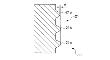
この実施形態では、口金部2の外周に対するねじ部3の形成時、一段目ねじ山3aが、図6に示すように、二段目ねじ山3b及び三段目ねじ山3cの高さより予め若干低い寸法Δで形成されている。
即ち、図4に示すように、中子11のねじ形成部21においては、一段目ねじ形成部21aの高さが、二段目ねじ形成部21b及び三段目ねじ形成部21cより若干低い寸法Δで形成され、これによって、中子11と外子12とによってボトル缶体1の口金部2にねじ部3を形成したとき、図6に実線にて示すように、口金部2のねじ始まり部3A側である一段目ねじ山3aが、二段目ねじ山3b及び三段目ねじ山3cより寸法Δ分だけ、予め低く形成されるようになっている。
この場合、Δとしては、例えば0.8mmのねじ山高さを設定値とすると、それより0.1mm程度低い値となっており、従って、0.7mm程度なっているが、厳密には適宜選定するのが好ましい。
【0032】
また、中子11のねじ形成部21において、一段目ねじ形成部21aが二段目ねじ山3b、三段目ねじ山3cより低くなっている範囲としては、本例では、図5に示すように、ねじ山領域Lを含む90度の角度範囲αである。この場合、一段目ねじ形成部21aのねじ始まり部21Aを0度とし、そこからねじ方向に90度の角度範囲αである。
【0033】
但し、90度の範囲に限らず、ねじ部3の巻数の変化やねじ山が押し潰される可能性の領域等を考慮すれば、180度までの角度範囲にするのが概ね良好で、より好ましいのは、100〜140度(α1)の角度範囲である。
なお、ねじ形成部21のねじ始まり部21Aとは、口金部2に形成されたねじ部3がネジとして有効に機能する部分であり、ねじ部3のねじ始まり部3Aに相当する。従って、ねじ終わり部21B及びねじ部3のねじ終わり部3Bもそれに準じている。
なお、図1〜図6において、図8〜図11と同一部分には同一符号を付している。
【0034】
このねじ成形装置10は、上記のように構成されているので、次に、その動作に関連して本発明方法の一実施形態について説明する。
まず、ボトル缶体1にねじ部3を設けるため、図1に示すように、ダイリング31及びリング状中空弾性部材32からなるワーク保持部30に底部が保持されたボトル缶体1が、対向する位置に位置決めされ、ワーク保持部30の前進により円筒面46bがボトル缶体1の肩部から缶胴部に嵌め込まれ、次いで、ワーク保持部30がより前進して押さえ環47がストッパー部材35に当接し、第二ハウジング42及び第三ハウジング44の前進が停止され、ワーク保持部30が更に前進して第一ハウジング41と第二ハウジング42との軸方向の間隔が狭められる。
【0035】
このとき、第一ハウジング41が、図2に示すように所定位置まで前進することで、第一ハウジング41が第二ハウジング42に対して移動し、カムローラC1、C2が第一ハウジングの斜面41a、41bに沿ってそれぞれ移動すると、それに伴って中子11がボトル缶体の口金部2内周部に移動して当接すると共に、外子12が口金部2外周部に移動して当接することにより、中子11と外子12とで口金部2を挟み込み、この状態でさらに装置全体が軸心O周りに回転することで、口金部2に図6に実線にて示すようなねじ部3が形成されることとなる。
【0036】
その場合、中子11と外子12との回転によって2.2巻のねじ部3を口金部2の外周面に沿って形成すると、中子11の一段目ねじ形成部21aの高さが二段目ねじ形成部21b、三段目ねじ形成部21cより低くなっているので、口金部2に設けられたねじ山領域のうち、一段目ねじ山3aが二段目ねじ山3b、三段目ねじ山3cのそれぞれの高さより低く形成される。
【0037】
このようにして口金部2の外周にねじ部3が形成された後、このねじ部3を有する口金部2の先端にカール部8を設けるため、図示しないカールかしめ装置によってカールかしめ工程を行うと、カールかしめ装置がボトル缶体1を缶底方向に押圧しながら口金部2の先端を外側から内側に折り返してカール部8(図9及び図11)を形成するので、口金部2の先端が押圧力を受け、口金部2における一段目ねじ山3aが押し潰されることで、一段目ねじ山3aが図6の実線から鎖線のように拡径される。
【0038】
この場合、前述のように、口金部2における一段目ねじ山3aが、二段目ねじ山3b及び三段目ねじ山3cの高さより予め低い寸法Δで形成されているので、カールかしめ装置の押圧力で押し潰されることで拡径されても、結果的には、二段目ねじ山3b及び三段目ねじ山3cと略同様の高さとなる。
【0039】
従って、本発明によれば、口金部2のねじ部3における一段目ねじ山3aを予め低く形成しておき、その後、口金部2の先端にカールかしめ工程によって押圧力を作用させると、そのときの押圧力で一段目ねじ山3aの高さを二段目ねじ山3b、三段目ねじ山3cの高さに略揃えることができるので、ねじ山を略均一化させることができる。
【0040】
そのため、このようなボトル缶体1にキャップ5が被着されると、キャップ5が天板側と開口端側とで略同径となる真直な有底円筒形状となるので、利用者がボトル缶体1を開栓した後で閉栓するとき、スムースに閉栓することができで違和感を与えることがなくなり、従来のようにすり鉢状のキャップとなる問題を解消することができ、それだけ信頼性を高めることができる。
【0041】
そして、このねじ成形装置10によれば、中子11における一段目ねじ形成部21aだけの高さを他のねじ形成部21b、21cより低くすることで、口金部2のねじ部3における一段目ねじ山3aを予め低く形成することができ、キャップの閉栓が良好となるねじ部3を的確に形成することができる。
【0042】
図7は、この発明の第二の実施形態を示す図であって、ボトル缶体の口金部に設けたねじ部を示す要部の拡大説明図である。
ボトル缶体1の口金部2に2.2巻のねじ部3を形成すると、三段からなるねじ山領域を除いた領域では、ねじ山が二段となる。
この実施形態では、そのような二段からなる領域内のねじ部3をも考慮したものであって、一段目のねじ山301の高さが、二段目のねじ山302の高さより低く形成されている。
【0043】
つまり、一段目のねじ山301は、三段に重なる領域(L)とねじ終わり部の不完全ねじ部とを除く領域内にあって、かつその高さを、二段目ねじ山302のより寸法Δ分だけ低く形成したものである。そのため、その高さに応じ、ねじ成形装置10の中子11のねじ形成部21は、上記ねじ山301、302の高さに応じて形成されている。
この実施形態によれば、一段目ねじ山301の高さが二段目ねじ山302の高さより低く形成されているので、カールかしめ工程による押圧力で押し潰されて拡径することで、一段目ねじ山301を二段目ねじ山302の高さと略同等の高さにすることができる。
【0044】
また、図示実施形態では、ねじ成形装置10がボトル缶体1の口金部2に2.2巻のねじ部3を形成した例を示したが、巻数をそれ以上増やした場合、例えば2.5巻のような巻数に形成した場合にも適用することができ、図示実施形態に限定されるものではない。
また、図示実施形態では、ねじ成形装置10が、口金部2の外周に当接しながら中子11と共に軸心O周りに回転する外子12を用いた例を示したが、外子12の代わりとして、中子11と共にねじ部3を形成できる他の外側体を用いてもよく、図示例に限定されるものではない。
【0045】
【発明の効果】
以上説明したように、請求項1に係る発明によれば、ねじ部の形成時、ボトル缶体の口金部の先端側に位置する一段目ねじ山の高さを、所定の角度範囲で他段目のねじ山より低く形成しておき、口金部がその後に押圧力を受けることで、一段目ねじ山が他段目のねじ山と略同等の高さとなる結果、ねじ部の巻数を増やしても、全てのねじ山を良好に形成することができる効果が得られる。
【0046】
請求項2に係る発明によれば、ねじ部のねじ始まり部から90度の範囲で一段目のねじ山の高さが他段目のねじ山より低くなっているので、ねじ山が潰されて拡径する範囲の一段目ねじ山を確実にカバーすることができる効果が得られる。
。
【0047】
請求項3に係る発明によれば、中子の一段目ねじ形成部が、所定の角度範囲で他段目のねじ形成部より低く形成されているので、ボトル缶体の口金部の外周には一段目ねじ山を他段目ねじ山より確実に低く形成できるという効果が得られる。
【図面の簡単な説明】
【図1】 この発明を実施するためのねじ成形装置を示す説明図である。
【図2】 ねじ成形装置がボトル缶体の口金部にねじ部を形成している状態を示す説明図である。
【図3】 ねじ成形装置の中子を示す外観図である。
【図4】 図3の中子におけるねじ形成部の拡大図である。
【図5】 同じく図3のA矢視に相当する図である。
【図6】 ボトル缶体の口金部にねじ部を形成した状態を示す説明図である。
【図7】 この発明の第二の実施形態を示す図であって、ボトル缶体の口金部に設けたねじ部を示す要部の拡大説明図である。
【図8】 ボトル缶体にねじ部を形成するまでの工程を示す説明図である。
【図9】 ねじ部を有するボトル缶体にキャップを被着する説明図である。
【図10】 ボトル缶体の口金部に2.2巻のねじ部を設けたときの説明図である。
【図11】 ボトル缶のねじ部に生じた従来の問題点を示す説明図である。
【符号の説明】
1 ボトル缶体
2 口金部
3 ねじ部
3a、301 一段目ねじ山
3b、302 二段目ねじ山
3c 三段目ねじ山
3A ねじ始まり部
3B ねじ終わり部
10 ねじ成形装置
11 中子
12 外子(外側体)
21 中子のねじ形成部
21a 中子のねじ形成部における一段目ねじ形成部[0001]
BACKGROUND OF THE INVENTION
This invention includes a base part forming process for forming the threaded portion in order to deposit the cap to the mouth section of the bottle can member, about that thread forming device.
[0002]
[Prior art]
A so-called bottle can body obtained by drawing a metal can body is formed with a base at the opening of the bottomed tubular can body, and a cap is attached to the outer periphery of the base. A thread portion is formed for this purpose.
[0003]
In order to produce a bottle can body having such a threaded portion, when a bottomed cylindrical bottle can body is formed in advance, the opening of the bottle can body, as shown in FIG. The diameter is once reduced to form the
In that case, when the
[0004]
Although the conventional screw forming apparatus is not shown in the drawing, a bottle can body while a core contacting the inner peripheral surface of the
[0005]
Further, the bottle can body 1 in which the threaded
[0006]
[Problems to be solved by the invention]
As described above, the conventional screw forming apparatus is configured such that the core that contacts the inner peripheral surface of the
[0007]
However, when the number of turns of the screw portion is about 1.7, as shown in FIG. 9, a portion having two
[0008]
In order to solve the above problem, an attempt has been made to increase the number of turns of the
[0009]
By the way, when the
[0010]
However, in this case, since the three-
[0011]
Thus, when the first
[0012]
The
[0013]
The present invention has been made in consideration of such circumstances, and its purpose is to make all the screw portions of the base portion substantially equal without regard to the curl caulking process even if the number of turns of the screw portion is increased. Another object is to provide a screw forming apparatus for a bottle can body that can accurately carry out the above method.
[0014]
[Means for Solving the Problems]
In order to achieve the above object, the present invention proposes the following means.
The invention according to
[0015]
According to the method for forming the cap part of the bottle can body according to the present invention, the height of the first-stage screw thread located on the tip side of the cap part of the bottle can body when the screw part is formed can be set within a predetermined angle range. If the bottle can body is subjected to a pressing force in the curl caulking process in this state, the first stage thread is crushed and expanded in diameter, so the first stage thread is The height is substantially the same as that of the other stage threads, and all the threads can be formed well. In this case, since the height of the first stage thread is lower than that of the other stage in the range of 90 degrees from the screw start part of the thread part, the thread is crushed by the pressing force in the curl caulking process. Thus, the first stage screw thread in the range where the diameter is expanded can be reliably covered.
[0017]
Further, the molding apparatus of the present invention is brought into contact with the inner peripheral surface of the base part before the formation of the curled portion of the cap tip of the bottle can member, and said to provide a threaded portion to be formed on the base part to the outer periphery A core having a screw forming portion and an outer body that contacts the outer peripheral surface of the base portion and has a screw forming portion having a shape corresponding to the screw forming portion of the core on the outer periphery. A screw forming apparatus for forming a screw part having a number of turns having a plurality of screw thread regions on the outer periphery of the base part, the body rotating around the axis of the bottle can body while sandwiching the base part. The screw forming portion of the core is a first-stage screw forming portion that forms the first-step screw thread in the screw thread region of the base portion, and the screw portion formed in the base portion does not include an incomplete screw portion. other in at least 90 degrees angular range from the screw starts portion that functions effectively as a Characterized in that it is formed lower than the thread forming portion of the eye.
[0018]
According to the screw forming apparatus according to the present invention, the first-stage screw forming portion of the core is formed lower than the other-stage screw forming portion within a predetermined angle range, so that the outer periphery of the base portion of the bottle can body is formed. Can make the first stage thread lower than the other stage thread reliably.
[0023]
DETAILED DESCRIPTION OF THE INVENTION
Embodiments of the present invention will be described below with reference to the drawings. 1 to 6 are views showing a base part forming method according to an embodiment of the present invention. FIG. 1 is an explanatory view showing a screw forming apparatus for performing the base part forming method, and FIG. FIG. 3 is an explanatory view showing a state in which the forming device forms a screw portion in the cap portion of the bottle can body, FIG. 3 is an external view showing the core of the screw forming device, and FIG. 4 is a view of the screw forming portion in the core of FIG. FIG. 5 is an enlarged view, FIG. 5 is a view corresponding to the arrow A in FIG. 3, and FIG. 6 is an explanatory view showing a state in which a screw portion is formed in the base portion of the bottle can body.
Before explaining the base part forming method of this embodiment, the bottle can
[0024]
The screw forming apparatus for carrying out the base part forming method is roughly divided into a core 11 that is in contact with the inner peripheral surface of the
[0025]
As shown in FIGS. 1 and 2, the
[0026]
The
[0027]
In FIGS. 1 and 2,
The
[0028]
As shown in FIG. 1, when the bottle can
[0029]
At this time, as the
[0030]
In that case, the
[0031]
In this embodiment, when the
That is, as shown in FIG. 4, in the
In this case, as Δ, for example, when a thread height of 0.8 mm is set as a set value, the value is about 0.1 mm lower than that, and therefore is about 0.7 mm. It is preferable to do this.
[0032]
Further, in the
[0033]
However, not only in the range of 90 degrees, but considering the change in the number of turns of the
The
1 to 6, the same parts as those in FIGS. 8 to 11 are denoted by the same reference numerals.
[0034]
Since the
First, since the
[0035]
At this time, as the
[0036]
In that case, if the
[0037]
After the
[0038]
In this case, as described above, the first-
[0039]
Therefore, according to the present invention, when the first-
[0040]
Therefore, when the
[0041]
According to the
[0042]
FIG. 7 is a diagram showing a second embodiment of the present invention, and is an enlarged explanatory view of a main part showing a screw portion provided in a cap part of a bottle can body.
When the
In this embodiment, the
[0043]
In other words, the
According to this embodiment, since the height of the first-
[0044]
In the illustrated embodiment, an example in which the
In the illustrated embodiment, the example in which the
[0045]
【The invention's effect】
As described above, according to the first aspect of the present invention, when the threaded portion is formed, the height of the first-stage screw thread located on the tip side of the mouthpiece portion of the bottle can body is set to another step within a predetermined angle range. It is formed lower than the thread of the eye, and the base part receives a pressing force after that, so that the first stage thread is almost the same height as the other stage thread, increasing the number of turns of the thread part. However, the effect that all the threads can be formed well is obtained.
[0046]
According to the invention of
.
[0047]
According to the invention of
[Brief description of the drawings]
FIG. 1 is an explanatory view showing a screw forming apparatus for carrying out the present invention.
FIG. 2 is an explanatory view showing a state in which the screw forming device forms a screw portion in a cap portion of the bottle can body.
FIG. 3 is an external view showing a core of a screw forming apparatus.
4 is an enlarged view of a screw forming portion in the core of FIG. 3;
FIG. 5 is a view corresponding to the arrow A in FIG.
FIG. 6 is an explanatory view showing a state in which a screw portion is formed in the base portion of the bottle can body.
FIG. 7 is a view showing a second embodiment of the present invention, and is an enlarged explanatory view of a main part showing a screw part provided in a base part of a bottle can body.
FIG. 8 is an explanatory view showing a process until a screw part is formed on the bottle can body.
FIG. 9 is an explanatory view of attaching a cap to a bottle can body having a threaded portion.
FIG. 10 is an explanatory diagram when a screw portion of 2.2 turns is provided on the base portion of the bottle can body.
FIG. 11 is an explanatory view showing a conventional problem that has occurred in the screw portion of the bottle can.
[Explanation of symbols]
DESCRIPTION OF
21 Core
Claims (2)
前記カール部を形成する前のねじ部の形成時、ボトル缶体の口金部の先端側に位置する一段目ねじ山の高さを、不完全ねじ部を含まずねじとして有効に機能するねじ始まり部から少なくとも90度の角度範囲で他段目のねじ山より低く形成しておくことを特徴とするボトル缶体の口金部成形方法。A cap of a bottle can body that forms a curled portion formed by folding back the tip of the cap portion of the bottle can body and a screw portion having a plurality of screw thread regions from the tip end side of the cap portion toward the bottom of the can. In the part molding method,
Beginning screw functions effectively during the formation of the front of the threaded portion, the first-stage threads located on the distal end side of the mouth section of the bottle can member height, as a screw not include the incomplete thread portion for forming the curled portion A method for forming a cap portion of a bottle can body, wherein the cap portion is formed to be lower than the thread of the other step in an angle range of at least 90 degrees from the portion.
中子と外側体が前記口金部を挟み込みながらボトル缶体の軸心周りに回転し、前記口金部の外周に対して、複数段からなるねじ山領域を有する巻数のねじ部を形成するねじ成形装置であって、
中子の前記ねじ形成部は、口金部の前記ねじ山領域内の一段目ねじ山を形成する一段目ねじ形成部を、口金部に形成されるねじ部が不完全ねじ部を含まずねじとして有効に機能するねじ始まり部から少なくとも90度の角度範囲で他段目のねじ形成部より低く形成されていることを特徴とするボトル缶体のねじ成形装置。And the core having a thread forming portion for providing the the inner peripheral surface of the base part abuts, and a screw portion to be formed on the mouth section on an outer periphery of before forming the curled portion of the cap tip of the bottle can member An outer body that contacts the outer peripheral surface of the base portion and has a screw forming portion having a shape corresponding to the screw forming portion of the core on the outer periphery,
Screw forming in which the core and the outer body rotate around the axis of the bottle can body while sandwiching the base part, and form a screw part having a number of turns having a plurality of screw thread regions on the outer periphery of the base part. A device,
The screw forming portion of the core is a first-stage screw forming portion that forms a first-stage screw thread in the screw thread region of the base portion, and the screw portion formed in the base portion does not include an incomplete screw portion. A screw forming apparatus for a bottle can body, wherein the screw forming apparatus is formed to be lower than a screw forming portion at the other stage in an angle range of at least 90 degrees from a screw starting portion that functions effectively.
Priority Applications (22)
| Application Number | Priority Date | Filing Date | Title |
|---|---|---|---|
| JP2002233917A JP4570838B2 (en) | 2002-08-09 | 2002-08-09 | Method of forming a cap part of a bottle can body and screw forming apparatus |
| PCT/JP2002/013840 WO2003057572A1 (en) | 2001-12-28 | 2002-12-27 | Bottle container, bottle, and screw forming device |
| CN200710007368.0A CN100575196B9 (en) | 2001-12-28 | 2002-12-27 | Bottle container and bottle |
| AT02795440T ATE469038T1 (en) | 2001-12-28 | 2002-12-27 | BOTTLE, METHOD OF PRODUCTION THEREOF AND THREAD PRODUCING APPARATUS |
| ES02795440T ES2344194T3 (en) | 2001-12-28 | 2002-12-27 | BOTTLE, BOTTLE PRODUCTION PROCEDURE AND THREAD FORMATION DEVICE. |
| AU2002361134A AU2002361134A1 (en) | 2001-12-28 | 2002-12-27 | Bottle container, bottle, and screw forming device |
| KR1020117020440A KR101259314B1 (en) | 2001-12-28 | 2002-12-27 | Method of cap screwing for bottle container |
| CA2790032A CA2790032C (en) | 2001-12-28 | 2002-12-27 | Bottle can member, bottle, and thread forming device |
| CNB028261321A CN1309619C (en) | 2001-12-28 | 2002-12-27 | Bottles, bottles and thread forming devices |
| DE60236545T DE60236545D1 (en) | 2001-12-28 | 2002-12-27 | BOTTLE, METHOD AND MANUFACTURING DEVICE |
| KR1020107009813A KR101160496B1 (en) | 2001-12-28 | 2002-12-27 | Bottle container, bottle, and screw forming device |
| KR1020107020072A KR101133003B1 (en) | 2001-12-28 | 2002-12-27 | Bottle container, bottle, and screw forming device |
| EP02795440A EP1468925B1 (en) | 2001-12-28 | 2002-12-27 | Bottle, method for producing the bottle and screw forming device |
| US10/500,344 US7798357B2 (en) | 2001-12-28 | 2002-12-27 | Bottle can member, bottle, and thread forming device |
| CA2471825A CA2471825C (en) | 2001-12-28 | 2002-12-27 | Bottle can member, bottle, and thread forming device |
| KR1020047010080A KR101017883B1 (en) | 2001-12-28 | 2002-12-27 | Bottle containers, bottles, and screw forming devices |
| KR1020117004807A KR101246992B1 (en) | 2001-12-28 | 2002-12-27 | Bottle container, bottle, and screw forming device |
| KR1020127011346A KR20120048720A (en) | 2001-12-28 | 2002-12-27 | Bottle container, bottle, and screw forming device |
| US12/874,465 US8740001B2 (en) | 2001-12-28 | 2010-09-02 | Bottle can member, bottle, and thread forming device |
| US12/874,557 US8132439B2 (en) | 2001-12-28 | 2010-09-02 | Bottle can member, bottle, and thread forming device |
| US12/874,520 US8037734B2 (en) | 2001-12-28 | 2010-09-02 | Bottle can member, bottle, and thread forming device |
| US13/475,242 US8499601B2 (en) | 2001-12-28 | 2012-05-18 | Bottle can member, bottle, and thread forming device |
Applications Claiming Priority (1)
| Application Number | Priority Date | Filing Date | Title |
|---|---|---|---|
| JP2002233917A JP4570838B2 (en) | 2002-08-09 | 2002-08-09 | Method of forming a cap part of a bottle can body and screw forming apparatus |
Related Child Applications (1)
| Application Number | Title | Priority Date | Filing Date |
|---|---|---|---|
| JP2007317996A Division JP4680976B2 (en) | 2007-12-10 | 2007-12-10 | Bottle can body and bottle |
Publications (2)
| Publication Number | Publication Date |
|---|---|
| JP2004074168A JP2004074168A (en) | 2004-03-11 |
| JP4570838B2 true JP4570838B2 (en) | 2010-10-27 |
Family
ID=32018917
Family Applications (1)
| Application Number | Title | Priority Date | Filing Date |
|---|---|---|---|
| JP2002233917A Expired - Lifetime JP4570838B2 (en) | 2001-12-28 | 2002-08-09 | Method of forming a cap part of a bottle can body and screw forming apparatus |
Country Status (1)
| Country | Link |
|---|---|
| JP (1) | JP4570838B2 (en) |
Cited By (3)
| Publication number | Priority date | Publication date | Assignee | Title |
|---|---|---|---|---|
| JP2018135153A (en) * | 2016-12-27 | 2018-08-30 | ユニバーサル製缶株式会社 | Bottle can, bottle can with cap |
| US11560250B2 (en) | 2006-03-06 | 2023-01-24 | Plastipak Packaging, Inc. | Lightweight plastic container and preform |
| US12391424B2 (en) | 2007-05-16 | 2025-08-19 | Plastipak Packaging, Inc. | Lightweight plastic container and preform |
Families Citing this family (8)
| Publication number | Priority date | Publication date | Assignee | Title |
|---|---|---|---|---|
| JP4497843B2 (en) * | 2002-09-02 | 2010-07-07 | 武内プレス工業株式会社 | Metal container manufacturing method and metal container |
| JP2006052000A (en) * | 2004-08-16 | 2006-02-23 | Alcoa Closure Systems Japan Ltd | Metal container, closure device, and drink enclosed in container |
| JP4667854B2 (en) * | 2004-12-24 | 2011-04-13 | ユニバーサル製缶株式会社 | Bottle can and manufacturing method thereof |
| JP5254701B2 (en) * | 2008-08-18 | 2013-08-07 | 大和製罐株式会社 | Metal can container |
| US9339864B2 (en) | 2012-03-27 | 2016-05-17 | Universal Can Corporation | Manufacturing method and manufacturing apparatus of screw-threaded bottle-can |
| JP6347337B1 (en) | 2016-12-22 | 2018-06-27 | 東洋製罐株式会社 | Metal bottle manufacturing method |
| JP7153520B2 (en) * | 2018-10-02 | 2022-10-14 | アルテミラ製缶株式会社 | Method for manufacturing threaded bottle cans |
| JP7447443B2 (en) * | 2018-12-04 | 2024-03-12 | アルテミラ製缶株式会社 | can body |
-
2002
- 2002-08-09 JP JP2002233917A patent/JP4570838B2/en not_active Expired - Lifetime
Cited By (6)
| Publication number | Priority date | Publication date | Assignee | Title |
|---|---|---|---|---|
| US11560250B2 (en) | 2006-03-06 | 2023-01-24 | Plastipak Packaging, Inc. | Lightweight plastic container and preform |
| US11834222B2 (en) | 2006-03-06 | 2023-12-05 | Plastipak Packaging, Inc. | Lightweight plastic container and preform |
| US12454385B2 (en) | 2006-03-06 | 2025-10-28 | Plastipak Packaging, Inc. | Lightweight plastic container and preform |
| US12391424B2 (en) | 2007-05-16 | 2025-08-19 | Plastipak Packaging, Inc. | Lightweight plastic container and preform |
| JP2018135153A (en) * | 2016-12-27 | 2018-08-30 | ユニバーサル製缶株式会社 | Bottle can, bottle can with cap |
| JP7220983B2 (en) | 2016-12-27 | 2023-02-13 | アルテミラ製缶株式会社 | bottle can, bottle can with cap |
Also Published As
| Publication number | Publication date |
|---|---|
| JP2004074168A (en) | 2004-03-11 |
Similar Documents
| Publication | Publication Date | Title |
|---|---|---|
| JP4680976B2 (en) | Bottle can body and bottle | |
| JP5090290B2 (en) | Bottle can | |
| JP5855233B2 (en) | Threaded bottle can manufacturing method | |
| JP5857038B2 (en) | Threaded bottle can manufacturing method | |
| JP4570838B2 (en) | Method of forming a cap part of a bottle can body and screw forming apparatus | |
| US20050067365A1 (en) | Bottle container, bottle, and screw forming device | |
| JP4131808B2 (en) | Bottle can screw forming apparatus and bottle can manufacturing method | |
| JP2005263230A (en) | Capping method | |
| JP4342988B2 (en) | Bottle can body manufacturing apparatus and bottle can body manufacturing method | |
| JP4137552B2 (en) | Thread forming apparatus and bottle can body manufacturing method | |
| JP6546946B2 (en) | Bottle with cap | |
| JP7153520B2 (en) | Method for manufacturing threaded bottle cans | |
| EP3560620A1 (en) | Method for manufacturing metal bottle, and metal bottle | |
| JP2018114989A (en) | Bottle can | |
| JP2006001619A (en) | Manufacturing method for bottle-shaped cans | |
| JP4267276B2 (en) | Bottle can with cap and capping method | |
| JP4245916B2 (en) | Cap material, bottled can with cap and method for producing cap material | |
| JP7170018B2 (en) | bottle can | |
| JP6748406B2 (en) | Capping method | |
| JP2018127229A (en) | Bottle can | |
| JP6476219B2 (en) | Manufacturing method for bottle cans | |
| JP7126459B2 (en) | bottle can | |
| US1689605A (en) | Method and apparatus for forming an interiorly-beaded or looped tearing-strip can | |
| JP6989406B2 (en) | Metal bottle | |
| JP2006076608A (en) | Capping device and cap screw forming method |
Legal Events
| Date | Code | Title | Description |
|---|---|---|---|
| A621 | Written request for application examination |
Free format text: JAPANESE INTERMEDIATE CODE: A621 Effective date: 20050325 |
|
| A711 | Notification of change in applicant |
Free format text: JAPANESE INTERMEDIATE CODE: A712 Effective date: 20060519 |
|
| RD03 | Notification of appointment of power of attorney |
Free format text: JAPANESE INTERMEDIATE CODE: A7423 Effective date: 20060613 |
|
| A131 | Notification of reasons for refusal |
Free format text: JAPANESE INTERMEDIATE CODE: A131 Effective date: 20071009 |
|
| RD02 | Notification of acceptance of power of attorney |
Free format text: JAPANESE INTERMEDIATE CODE: A7422 Effective date: 20071120 |
|
| A521 | Request for written amendment filed |
Free format text: JAPANESE INTERMEDIATE CODE: A523 Effective date: 20071210 |
|
| RD04 | Notification of resignation of power of attorney |
Free format text: JAPANESE INTERMEDIATE CODE: A7424 Effective date: 20071116 |
|
| A131 | Notification of reasons for refusal |
Free format text: JAPANESE INTERMEDIATE CODE: A131 Effective date: 20080527 |
|
| A521 | Request for written amendment filed |
Free format text: JAPANESE INTERMEDIATE CODE: A523 Effective date: 20080717 |
|
| A02 | Decision of refusal |
Free format text: JAPANESE INTERMEDIATE CODE: A02 Effective date: 20090707 |
|
| A521 | Request for written amendment filed |
Free format text: JAPANESE INTERMEDIATE CODE: A523 Effective date: 20100705 |
|
| A01 | Written decision to grant a patent or to grant a registration (utility model) |
Free format text: JAPANESE INTERMEDIATE CODE: A01 |
|
| A61 | First payment of annual fees (during grant procedure) |
Free format text: JAPANESE INTERMEDIATE CODE: A61 Effective date: 20100811 |
|
| FPAY | Renewal fee payment (event date is renewal date of database) |
Free format text: PAYMENT UNTIL: 20130820 Year of fee payment: 3 |
|
| R150 | Certificate of patent or registration of utility model |
Ref document number: 4570838 Country of ref document: JP Free format text: JAPANESE INTERMEDIATE CODE: R150 Free format text: JAPANESE INTERMEDIATE CODE: R150 |
|
| R250 | Receipt of annual fees |
Free format text: JAPANESE INTERMEDIATE CODE: R250 |
|
| R250 | Receipt of annual fees |
Free format text: JAPANESE INTERMEDIATE CODE: R250 |
|
| R250 | Receipt of annual fees |
Free format text: JAPANESE INTERMEDIATE CODE: R250 |
|
| R250 | Receipt of annual fees |
Free format text: JAPANESE INTERMEDIATE CODE: R250 |
|
| R250 | Receipt of annual fees |
Free format text: JAPANESE INTERMEDIATE CODE: R250 |
|
| R250 | Receipt of annual fees |
Free format text: JAPANESE INTERMEDIATE CODE: R250 |
|
| R250 | Receipt of annual fees |
Free format text: JAPANESE INTERMEDIATE CODE: R250 |
|
| R250 | Receipt of annual fees |
Free format text: JAPANESE INTERMEDIATE CODE: R250 |
|
| R250 | Receipt of annual fees |
Free format text: JAPANESE INTERMEDIATE CODE: R250 |
|
| EXPY | Cancellation because of completion of term |