JP4566570B2 - Optical equipment - Google Patents
Optical equipment Download PDFInfo
- Publication number
- JP4566570B2 JP4566570B2 JP2004024924A JP2004024924A JP4566570B2 JP 4566570 B2 JP4566570 B2 JP 4566570B2 JP 2004024924 A JP2004024924 A JP 2004024924A JP 2004024924 A JP2004024924 A JP 2004024924A JP 4566570 B2 JP4566570 B2 JP 4566570B2
- Authority
- JP
- Japan
- Prior art keywords
- region
- signal
- lock
- lock member
- lens
- Prior art date
- Legal status (The legal status is an assumption and is not a legal conclusion. Google has not performed a legal analysis and makes no representation as to the accuracy of the status listed.)
- Expired - Fee Related
Links
Images


Classifications
-
- G—PHYSICS
- G02—OPTICS
- G02B—OPTICAL ELEMENTS, SYSTEMS OR APPARATUS
- G02B27/00—Optical systems or apparatus not provided for by any of the groups G02B1/00 - G02B26/00, G02B30/00
- G02B27/64—Imaging systems using optical elements for stabilisation of the lateral and angular position of the image
- G02B27/646—Imaging systems using optical elements for stabilisation of the lateral and angular position of the image compensating for small deviations, e.g. due to vibration or shake
-
- G—PHYSICS
- G03—PHOTOGRAPHY; CINEMATOGRAPHY; ANALOGOUS TECHNIQUES USING WAVES OTHER THAN OPTICAL WAVES; ELECTROGRAPHY; HOLOGRAPHY
- G03B—APPARATUS OR ARRANGEMENTS FOR TAKING PHOTOGRAPHS OR FOR PROJECTING OR VIEWING THEM; APPARATUS OR ARRANGEMENTS EMPLOYING ANALOGOUS TECHNIQUES USING WAVES OTHER THAN OPTICAL WAVES; ACCESSORIES THEREFOR
- G03B5/00—Adjustment of optical system relative to image or object surface other than for focusing
-
- G—PHYSICS
- G03—PHOTOGRAPHY; CINEMATOGRAPHY; ANALOGOUS TECHNIQUES USING WAVES OTHER THAN OPTICAL WAVES; ELECTROGRAPHY; HOLOGRAPHY
- G03B—APPARATUS OR ARRANGEMENTS FOR TAKING PHOTOGRAPHS OR FOR PROJECTING OR VIEWING THEM; APPARATUS OR ARRANGEMENTS EMPLOYING ANALOGOUS TECHNIQUES USING WAVES OTHER THAN OPTICAL WAVES; ACCESSORIES THEREFOR
- G03B2205/00—Adjustment of optical system relative to image or object surface other than for focusing
- G03B2205/0007—Movement of one or more optical elements for control of motion blur
-
- G—PHYSICS
- G03—PHOTOGRAPHY; CINEMATOGRAPHY; ANALOGOUS TECHNIQUES USING WAVES OTHER THAN OPTICAL WAVES; ELECTROGRAPHY; HOLOGRAPHY
- G03B—APPARATUS OR ARRANGEMENTS FOR TAKING PHOTOGRAPHS OR FOR PROJECTING OR VIEWING THEM; APPARATUS OR ARRANGEMENTS EMPLOYING ANALOGOUS TECHNIQUES USING WAVES OTHER THAN OPTICAL WAVES; ACCESSORIES THEREFOR
- G03B2205/00—Adjustment of optical system relative to image or object surface other than for focusing
- G03B2205/0053—Driving means for the movement of one or more optical element
-
- Y—GENERAL TAGGING OF NEW TECHNOLOGICAL DEVELOPMENTS; GENERAL TAGGING OF CROSS-SECTIONAL TECHNOLOGIES SPANNING OVER SEVERAL SECTIONS OF THE IPC; TECHNICAL SUBJECTS COVERED BY FORMER USPC CROSS-REFERENCE ART COLLECTIONS [XRACs] AND DIGESTS
- Y10—TECHNICAL SUBJECTS COVERED BY FORMER USPC
- Y10T—TECHNICAL SUBJECTS COVERED BY FORMER US CLASSIFICATION
- Y10T70/00—Locks
- Y10T70/70—Operating mechanism
- Y10T70/7051—Using a powered device [e.g., motor]
Description
本発明は、振れ補正機能を搭載した光学機器に関する。 The present invention relates to an optical apparatus equipped with a shake correction function.
従来のレンズ鏡筒は、第1の機能状態にする第1の位置と、第2の機能状態にする第2の位置との間を移動する移動部材と、移動部材を第1の位置と第2の位置の間で駆動させるためのステッピングモータを有した位置制御装置を有し、移動部材の第1の位置と第2の位置におけるステッピングモータのロータ位置をそれぞれ電気的に同位相とした構成となっている(例えば、特許文献1参照)。 The conventional lens barrel includes a moving member that moves between a first position that makes the first functional state and a second position that makes the second functional state, and moves the moving member to the first position and the second position. A position control device having a stepping motor for driving between two positions, wherein the rotor position of the stepping motor at the first position and the second position of the moving member is electrically in phase with each other (For example, see Patent Document 1).
また、第1の機能状態にする第1の位置と、第2の機能状態にする第2の位置との間を移動する移動部材と、移動部材を第1の位置と第2の位置の間で駆動させるためのステッピングモータを有し、第1と第2の位置の間の範囲を越えた位置に当接部が設けられていて、当接部と第1または第2の位置との間隔を、ステッピングモータの通電位相の半周期に対応する移動部材の移動量よりも、小さく設定した構成となっている。
上記のような従来例によれば、上記移動部材の駆動中にカメラより交換レンズが外さ
れて、駆動電圧の供給が途中で絶たれたり、レンズ本体に衝撃等が加わった時などに、上記移動部材が、不意に所定の基準位置より移動してしまった場合は、移動部材を当接部に当接させ、所定の基準位置(初期状態)に戻すような構成になっている。
According to the conventional example as described above, when the interchangeable lens is removed from the camera while the moving member is being driven and the supply of the driving voltage is interrupted in the middle or when an impact is applied to the lens body, When the moving member has unexpectedly moved from the predetermined reference position, the moving member is brought into contact with the contact portion and returned to the predetermined reference position (initial state).
しかし、このような構成では、移動部材を所定の基準位置(初期状態)にするたびに、移動部材が当接部に突き当たるため、突き当たった時に衝撃音が発生してしまう。また、移動部材の移動速度をさらに高速にした場合は、突き当たり時の衝撃力(破壊力)が増大するため、移動部材の移動伝達機構の耐久性が低下するおそれがある。 However, in such a configuration, every time when the moving member is set to a predetermined reference position (initial state), the moving member hits against the contact portion, so that an impact sound is generated when it hits. Further, when the moving speed of the moving member is further increased, the impact force (destructive force) at the time of contact increases, so that the durability of the moving transmission mechanism of the moving member may be reduced.
さらに、上記従来例によれば、衝撃力緩和のために、当接部を弾性部材で形成した構成となっているが、移動部材の移動速度を高速にして衝撃力が増大した場合や、ステップ角度がさらに小さいステッピングモータを使って、高精度化を図った場合には、弾性部材の弾性変形によって、当接部と第1または第2の位置との間隔が、ステッピングモータの通電位相の半周期に対応する移動部材の移動量よりも、大きくなってしまって、上記従来例の構成が成り立たなくなってしまう。 Further, according to the above conventional example, the contact portion is formed of an elastic member to reduce the impact force. However, when the impact force is increased by increasing the moving speed of the moving member, When a stepping motor with a smaller angle is used to achieve high accuracy, the distance between the contact portion and the first or second position is half of the energization phase of the stepping motor due to elastic deformation of the elastic member. It becomes larger than the moving amount of the moving member corresponding to the period, and the configuration of the conventional example is not realized.
本発明は、以上のような局面に鑑みてなされたもので、移動部材の当接部への衝突による衝撃音の発生を阻止し、移動部材の高速駆動化に対応した構造を持った位置制御装置、及びこれを備えた光学機器を提供することを目的とする。
The present invention has been made in view of the above situation, and prevents the generation of impact sound due to the collision of the moving member with the contact portion, and the position control has a structure corresponding to the high-speed driving of the moving member. device, and an object thereof to provide an optical apparatus having the same.
上記目的を達成するために、撮影光学系の光軸と直交する方向に移動して像振れを補正するためのレンズを保持するレンズ保持部材と、前記レンズ保持部材のロック及びロック解除を行うためのロック部材であって、前記レンズ保持部材を第1の位置にロックする第1の領域と、前記レンズ保持部材のロックを解除する第2の領域と、前記第1の領域および前記第2の領域の間の移行領域である第3の領域とで移動可能であるロック部材と、前記ロック部材を駆動するアクチュエータと、前記レンズ保持部材が前記第1の位置に存在するか否かに応じた位置信号を出力する第1の検出手段と、前記ロック部材が前記第1の領域および前記第2の領域のいずれかに位置する状態で第1の信号を出力し、前記ロック部材が前記第3の領域に位置する状態で前記第1の信号とは異なる第2の信号を出力する第2の検出手段と、前記アクチュエータを制御する制御手段と、を有する光学機器であって、前記ロック部材が前記第1の領域に位置すると判別したときは、前記アクチュエータを、前記ロック部材が前記第3の領域に移動する方向に、前記第1の信号が前記第2の信号に切り換わり、かつ前記切り換わり時点からの駆動量が第1の駆動量に達するまで駆動し、その後、前記ロック部材が前記第1の領域に移動する方向に、前記第2の信号が前記第1の信号に切り換わり、かつ前記切り換わり時点から前記第1の領域内の初期化位置に達するまで駆動し、前記ロック部材が前記第2の領域又は前記第3の領域に位置すると判別したときは、前記アクチュエータを前記ロック部材が前記第1の領域に移動する方向に前記第2の信号が前記第1の信号に切り換わり、かつ前記切り換わり時点から前記第1の領域内の初期化位置に達するまで駆動することを特徴とする。
To achieve the above object, a lens holding member that moves in a direction perpendicular to the optical axis of the photographing optical system to hold a lens for correcting image blur, and for locking and unlocking the lens holding member a locking member, the lens and the first region to lock the holding member in the first position, and a second area to unlock the previous SL lens holding member, the first region and the second Depending on whether or not the lock member movable in the third region, which is a transition region between the two regions, the actuator that drives the lock member, and the lens holding member are in the first position A first detection means for outputting a position signal; and a first signal in a state where the lock member is located in either the first region or the second region ; Located in
本願発明の位置制御装置の第1の構成によれば、第2の移動部材が第1から第3の領域のどこに位置する場合でも、2つの単純な検出手段(第1および第2の検出手段)を用いて、第1の領域内の特定位置(第1の位置)に正確に移動させることができる。 According to the first configuration of the position control device of the present invention, two simple detection means (first and second detection means) regardless of where the second moving member is located in the first to third regions. ) Can be accurately moved to a specific position ( first position ) in the first region.
また、例えば、第2の移動部材の移動範囲を制限する阻止部が第1の領域及第2の領域に設けられている場合であっても、第2の移動部材を該阻止部に当接させることなく、第1の位置に移動させることができるため、当接時に異音が発生するのを阻止することができる。 Further, for example, even when a blocking portion that restricts the movement range of the second moving member is provided in the first region and the second region, the second moving member is brought into contact with the blocking portion. without, since it is possible to move to the first position, it is possible to prevent the abnormal noise occurs during contact.
以下、本発明の実施例について説明する。 Examples of the present invention will be described below.
まず、本発明の振れ補正ユニットが搭載されたレンズシステムとカメラシステム(光学機器)の構成について説明する。
図15は、像振れ補正ユニットを搭載した、カメラシステム(レンズシステムを含む)の構成を示すブロック図である。
First, configurations of a lens system and a camera system (optical apparatus) on which the shake correction unit of the present invention is mounted will be described.
FIG. 15 is a block diagram showing a configuration of a camera system (including a lens system) equipped with an image blur correction unit.
同図において、200はカメラ本体、300は交換レンズ本体、201はマイクロコンピュータで構成されるカメラCPUで、後述するカメラ本体200内の種々の回路の動作を制御すると共に、レンズ本体300の装着時にはレンズ接点302とカメラ接点202が接続されて、レンズCPU301との通信を行うものである。203は外部より操作可能な電源スイッチであり、カメラCPU201を立ち上げてシステム内の各アクチュエータやセンサ等への電源供給及びシステムの動作を可能な状態とするためのスイッチである。204は外部より操作可能な2段ストローク式のレリーズスイッチで、その信号はカメラCPU201に入力される。
In the figure,
カメラCPU201は、レリーズスイッチ204が第1ストローク操作されると(SW1信号発生)、測光ユニット205による露光量の決定、焦点検出ユニット208による被写体の焦点検出結果に基づく後述の合焦ユニットへの駆動信号の出力、および合焦判定等を行って撮影準備状態に入り、第2ストローク操作されると(SW2信号発生)、レンズ本体300内のレンズCPU301(後述するレンズ本体300内の種々の装置回路の動作を制御すると共に、カメラ本体200に装着された時にはレンズ接点302とカメラ接点202が接続されて、カメラCPU201との通信を行うもの)に後述のレンズ本体300内の絞りユニットを駆動する駆動命令を送信するとともに、露光ユニット206に撮像素子207(例えば、CCD、CMOSイメージセンサ)への露光動作を開始させる動作信号を出力する。
When the
209は表示ユニットで、絞り値やシャッタスピードなどの各種撮影条件や、撮影枚数、電池残量、各種モードを、カメラCPU201の指令に応じて表示する。
A
303は外部より操作可能な像振れ補正作動切替スイッチ(以下、「ISスイッチ」と記す)であり、このISスイッチ303を操作することにより、後述の像振れ補正動作(以下、「IS動作」とも記す)を行わせるかどうかを選択すること(ONでIS動作を選択)ができる。
305は振れ補正ユニットであり、以下の6つの構成要素に大別される。第1は、振れ補正レンズとそれを保持する保持枠とから成る振れ補正光学系、第2は、振れ補正光学系を駆動するための駆動機構、第3は、移動した振れ補正光学系の位置を検出するための位置検出回路、第4は、振れ補正光学系を所定位置(光軸中心位置)にロックしたりロック解除(アンロック)したりすることのできるロック機構、第5は、ロック機構を駆動するためのロック駆動機構、第6はカメラの縦振れおよび横振れの加速度あるいは速度を検出して、振れ補正の対象となる振動状態を検出する振動検出回路である。
A
306は合焦ユニットであり、合焦レンズおよびその保持枠と、合焦レンズを目標位置まで駆動するための合焦レンズ駆動機構と、合焦レンズ駆動機構による駆動力を合焦レンズの移動力として伝達する伝達機構と、前述のようにカメラCPU201から送信された、合焦レンズの移動量の情報に従い、レンズCPU301によって制御され、合焦レンズ駆動機構に駆動指令を送る合焦レンズ駆動回路とから構成されている。
A focusing
307は絞りユニットであり、開口面積を設定する絞り機構と、絞り機構を駆動するための絞り機構駆動ユニットと、前述のようにカメラCPU201から送信された絞り動作命令に従い、レンズCPU301によって制御され、絞り機構駆動ユニットに駆動指令を送る絞り駆動回路とから構成されている。
図16は、図15に示したレンズシステムおよびカメラシステムにおける主要動作を示すフローチャートである。なお、図中記載の『Y』はYES、『N』はNOを意味する。まず、カメラ本体200の電源スイッチ203がONされ、レンズ本体300に電源の供給が開始(又は、新しい電池を入れられた場合、カメラ本体200にレンズ本体300が装着された場合などカメラ本体200とレンズ本体300との間で通信が開始)されたことを判別すると(S5001)、レンズCPU301は振れ補正ユニット305に通電を行い、振れ補正ユニット305のイニシャル動作を行う。
FIG. 16 is a flowchart showing main operations in the lens system and the camera system shown in FIG. In the figure, “Y” means YES, and “N” means NO. First, the
このイニシャル動作についての詳細は、本発明の振れ補正ユニットの機械的構成を説明した後に説明(後述)するが、概説すると、振れ補正ユニット305のロック機構のロック部材(振れ補正光学系の保持枠をロックする部材)を所定の基準位置に設定するための処理で、ロック機構の駆動途中での電源遮断や衝撃等で、ロック機構のロック部材の位置がズレて、現在のロック状態が所定の基準位置から特定できなくなってしまった時のために、必ず電源投入時にロック機構を駆動して、ロック部材を所定の基準位置に設定する処理である。
The details of the initial operation will be described (described later) after the description of the mechanical configuration of the shake correction unit of the present invention. However, generally speaking, the lock member of the lock mechanism of the shake correction unit 305 (the holding frame of the shake correction optical system). The member that locks the lock mechanism) is set to a predetermined reference position. The position of the lock member of the lock mechanism is displaced due to power interruption or impact during the drive of the lock mechanism, and the current lock state is In this case, the lock mechanism is always driven when the power is turned on to set the lock member at a predetermined reference position in case the reference position cannot be specified.
例えば、ロック駆動機構の駆動源として、ステッピングモータ(パルス駆動モータ)を用いた場合、所定の基準位置から目標位置までの駆動パルス数を制御することで、目標位置に到達させているため、所定の基準位置(現在の位置が基準位置から何パルス目のところか)が分からなくなると、目標位置までの正確なパルス数が算出できなくなる。このために、まず、所定の基準位置を定める動作が必要になる。
次に、カメラCPU201がレリーズスイッチ204のSW1信号が発生しているか否かを判別し(S5003)、発生していれば、レンズCPU301においてISスイッチ303がON(IS動作選択)になっているかを判別し(S5004)、IS動作が選択されていればステップS5005へ、選択されていなければステップS5019へ進む。
For example, when a stepping motor (pulse drive motor) is used as the drive source of the lock drive mechanism, the target position is reached by controlling the number of drive pulses from a predetermined reference position to the target position. If the reference position (the current position is the number of pulses from the reference position) is not known, the exact number of pulses up to the target position cannot be calculated. For this purpose, first, an operation for determining a predetermined reference position is required.
Next, the
ステップS5005では、レンズCPU301が内部タイマをスタートさせ、次にカメラCPU201が、測光ユニット205、焦点検出ユニット208による測光,焦点検出動作を行い、レンズCPU301が、合焦ユニット306による合焦動作、振れ補正ユニット305による振れ検出の開始、更にはロック駆動機構による振れ補正光学系のロック解除を行う(S5006)。
In step S5005, the
次に、レンズCPU301が上記タイマでのカウント結果が、所定の時間t1 に達したか否かを判別し、達していなければ達するまでこのステップに留まる(S5007)。これは、振動検出回路の出力信号が安定するまでの間、待機する為の処理である。その後、所定の時間t1 が経過すると、振動検出回路の出力信号によって演算される目標値信号と、位置検出回路の出力信号に基づいて、振れ補正ユニットの駆動機構によって振れ補正光学系を駆動し、振れ補正制御を開始する(S5008)。
Next, the
次に、カメラCPU201が、レリーズスイッチ204のSW2信号が発生しているか否かを判定し(S5009)、発生していなければ再びSW1信号が発生しているか否かの判別を行い(S5011)、もしSW1信号も発生していなければ、レンズCPU301が振れ補正制御を停止する(S5012)とともに、振れ補正光学系を所定の位置(光軸中心位置)にロックするようロック機構を駆動する(S5013)。
Next, the
また、ステップS5009でSW2信号は発生していないが、ステップS5011でSW1信号が発生していると判別した場合はステップS5009へ戻る。そして、このステップS5009でレリーズスイッチ204のSW2信号が発生したことを判別すると、レンズCPU301が絞りユニット307を制御し、同時にカメラCPU201が、露光ユニット206により撮像素子207への露光動作を行う(S5010)。
In step S5009, the SW2 signal is not generated, but if it is determined in step S5011 that the SW1 signal is generated, the process returns to step S5009. If it is determined in step S5009 that the SW2 signal of the
次いで、カメラCPU201がSW1信号の状態を調べ(S5011)、SW1信号が発生しなくなったらレンズCPU301が振れ補正制御を停止する(S5012)と共に、振れ補正光学系を所定の位置(光軸中心位置)にロック機構によりロックするよう、ロック駆動機構を駆動する(S5013)。
Next, the
以上の動作を終了すると、次にレンズCPU301は、上記タイマを一旦リセットして再度スタートさせ(S5014)、再びSW1信号が所定時間t2 内に発生するかどうかの判別を行う。もし振れ補正を停止してから所定時間t2 内に再度SW1信号が発生したならば、測光,AF(焦点検出動作及び合焦動作)及び振れ補正光学系のロック解除を行い(S5017)、振れ検出はそのまま継続されているので、直ちに目標値信号と位置検出回路の出力信号に基づいて、振れ補正光学系を駆動し、振れ補正制御を再び開始する(S5008)。以下、前述と同様の動作を繰り返す。
When the above operation is completed, the
このような所定時間t2の経過判定の処理をすることにより、撮影者がレリーズ操作を停止した後に再度レリーズ操作をした際に、その度に振動検出回路を起動してその出力安定まで待機するといった不都合を無くすことが可能になる。 By performing the process for determining the elapse of the predetermined time t2, when the photographer stops the release operation and then performs the release operation again, the vibration detection circuit is activated each time and waits until the output is stabilized. Inconvenience can be eliminated.
一方、振れ補正を停止してから所定時間t2以内にSW1信号が発生しなかった場合は(S5015)、振動検出回路の動作を停止する(S5018)。その後はステップS5003に戻り、SW1信号の発生待機の状態に入る。 On the other hand, if the SW1 signal is not generated within the predetermined time t2 after the shake correction is stopped (S5015), the operation of the vibration detection circuit is stopped (S5018). Thereafter, the process returns to step S5003, and enters the state of waiting for the generation of the SW1 signal.
ステップS5004でIS動作が選択されていなければ、カメラCPU201が測光、焦点検出動作を、レンズCPU301が合焦動作を、それぞれ実行する(S5019)。
次に、カメラCPU201がレリーズスイッチ204のSW2信号が発生しているか否かを調べ(S5020)、発生していなければ再びSW1信号が発生しているか否かの判別を行い(S5022)、SW1信号も発生していなければステップS5003に戻り、SW1信号の発生待機の状態に入る。また、ステップS5020でSW2信号は発生していないがSW1信号は発生していれば、ステップS5020へ戻る。そして、このステップS5020でレリーズスイッチ204にSW2信号が発生したことを検知すると、レンズCPU301が絞りユニット307を制御し、同時にカメラCPU201が露光ユニット206を制御して、撮像素子207への露光動作を開始する(S5021)。次いで、カメラCPU201がSW1信号の状態を調べ(S5022)、SW1信号が発生していなければステップS5022からステップS5003へ戻る。
本発明の実施例におけるカメラシステムでは、電源スイッチ203がOFFされるまで上記一連の動作を繰り返し、OFFされるとカメラCPU201とレンズCPU301との通信が終了しレンズ本体300への電源供給が終了する。
次に、本発明の振れ補正ユニットの機械的構成について説明する。
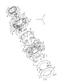
まず各部品について、概説する。図1は本発明の振れ補正ユニットの分解斜視図である。1は合成樹脂で形成されたベース部材、2は透磁率の高い鋼板で形成された第1のヨーク部材、3は永久磁石であり、矩形の4つの永久磁石3a−1、3b−1、3a−2、3b−2で構成されている。
If the IS operation is not selected in step S5004, the
Next, the
In the camera system according to the embodiment of the present invention, the above series of operations is repeated until the
Next, the mechanical configuration of the shake correction unit of the present invention will be described.
First, each part is outlined. FIG. 1 is an exploded perspective view of a shake correction unit of the present invention. 1 is a base member made of synthetic resin, 2 is a first yoke member made of steel plate with high magnetic permeability, 3 is a permanent magnet, and four rectangular
4は金属の線材を屈曲させて形成されたガイド部材で、第1のガイド部4aと第2のガイド部4bとを有している。5は合成樹脂材で形成され、振れ補正レンズ14を保持しているレンズ保持枠(第1の移動部材)、6a、6bは導線で形成されたコイル、7は透磁率の高い鋼板で形成された第2のヨーク部材、8は電気絶縁性の高い合成樹脂で形成された絶縁板、9は主に振れ補正制御回路の電気部品が実装された電気回路基板、10は合成樹脂で形成され、レンズ保持枠5の補正動作方向の移動を機械的にロックするロック機構であるロックリング(第2の移動部材)、11はロックリング10を駆動するためのアクチュエータで、ステッピングモータ(パルス駆動モータ)を採用している。
12はロックリング10の位置を検出するためのフォトインタラプタ(第2の検出手段)、13はフレキシブルプリント基板、15a、15bは発光素子、16a、16bは発光素子15から発せられた光を受光する受光素子(第1の検出手段)、17〜20は締結部材、21a〜21cは金属の線材で形成された支持軸である。
次に各部品の詳細と各部品の相互関係について説明する。
まず、ベース部材1に第1のヨーク部材2が取り付けられる。その際、ベース部材1に設けられた突出軸部1a−1〜1a−4に、第1のヨーク部材2に設けられた穴部2a−1〜2a−4をそれぞれ係合させる。また、ベース部材1に設けられた当接面部1b−1、1b−2に第1のヨーク部材2の端面を当接させ、締結部材17a、17bを第1のヨーク部材2の溝部2b−1、2b−2に挿通させて、ベース部材1の穴部1b−1−a、1b−2−aに係合させ、ベース部材1に第1のヨーク部材を固定する。
12 is a photo interrupter (second detection means) for detecting the position of the
Next, the details of each component and the mutual relationship between the components will be described.
First, the
次に、永久磁石3を第1のヨーク部材に設置する。その際、永久磁石3a−1と3b−1、3a−2と3b−2とで、ベース部材1の突出軸部1a−1と1a−2、1a−3と1a−4を挟むように配置する。それらが設置された状態を図2に示す。第1のヨーク部材に設置された永久磁石3は、磁気吸引力のため、第1のヨーク部材2に強力に保持されている。
Next, the
次に、フォトインタラプタ12は、フレキシブルプリント基板13に、その端子部12aを半田付けすることにより固定されている。そして、フレキシブルプリント基板13の穴部13a−1、13a−2に、ベース部材1に設けられた突出軸部1c−1、1c−2を係合させ、フレキシブルプリント基板13の端面を、ベース部材1の当接面部1c−1−a、1c−2−aに当接させ、締結部材18をフレキシブルプリント基板13の穴部13bに挿通させて、ベース部材1の穴部1dに係合させ、ベース部材1にフレキシブルプリント基板13を固定させる。
Next, the
その際、フォトインタラプタ12は、ベース部材1の穴部1mを挿通する。なお、ベース部材1の当接面部1c−1−a、1c−2−aに当接させるフレキシブルプリント基板13の端面部に補強板を設けるとフォトインタラプタの位置が安定する。なお、フォトインタラプタ12の端子12aは、フレキシブルプリント基板13を介して、電気回路基板9へ接続されていている。
At that time, the
次に、ガイド部材4の第1のガイド部4aは、ベース部材1に設けられた係合柱部1f、1gの係合穴部1f−1、1g−1に係合する。
Next, the
次に、レンズ保持枠5にコイル6が取り付けられる。その際、レンズ保持枠5に設けられた弾性変形可能な挟持片部5a−1、5a−2、5b−1、5b−2と、挟持座部5c−1、5c−2、5d−1、5d−2とでコイルを挟み込んで保持し、レンズ保持枠5に対する、光軸方向のコイルの相対移動を制限する構造になっている。
Next, the coil 6 is attached to the
また、挟持片部5a−1、5a−2、5b−1、5b−2の先端には係合突起部があり、これらの係合突起部をコイルの長穴部6a−1、6b−1に係合させることにより、レンズ保持枠5に対する、光軸方向及び光軸直交方向のコイルの相対移動を制限する構造になっている。
In addition, there are engaging projections at the tips of the sandwiching
次に、発光素子15a、15bは、レンズ保持枠5に熱カシメ等により取り付けられており、発光素子15a、15bから発せられた光は、レンズ保持枠5に形成された長穴部5e−1、5e−2を通過するようになっている。
Next, the
なお、上述のコイル6a、6b、発光素子15a、15bの各端子は、不図示のフレキシブルプリント基板を介して、電気回路基板9へ接続されていて、振れ補正制御を行うようになっている。
次に、レンズ保持枠5に設けられた係合柱部5i、5jの係合穴部5i−1、5j−1(図3参照)に、ガイド部材4の第2のガイド部4bが係合する。
次に、レンズ保持枠5の穴部5g−1〜5g−3には、支持軸21a〜21cが圧入等により取り付けられる。その際、支持軸21a〜21cを、ベース部材1の突出片部1h−1〜1h−3に設けられた長穴部1h−1−a〜1h−3−aに係合させているので、ベース部材1に対する、レンズ保持枠5の光軸方向の移動が制限される。
The terminals of the
Next, the
Next,
ガイド部材4の第1のガイド部4aがベース部材1に係合し、第2のガイド部4bがレンズ保持枠5に係合し、支持軸21a〜21cがベース部材1の長穴部1h−1−a〜1h−3−aに係合することで、レンズ保持枠5は、光軸周りの回転と光軸方向への移動が制限され、ピッチ方向(図中Y方向)とヨー方向(図中X方向)にのみ移動可能な構造となる。
The
なお、レンズ保持枠5に設けられた穴部5h−1と5h−2には、ベース部材1に設けられた軸部1i−1、1i−2が挿通するようになっているが、穴部5h−1、5h−2の直径は、軸部1i−1、1i−2の直径よりも大きく設定されている。これにより、穴部5h−1、5h−2の内周面が軸部1i−1、1i−2の外周面に当接するため、レンズ保持枠5のピッチ方向およびヨー方向の最大移動量が制限される。例えば、一方の穴部と軸部のみで移動量を制限し、他方では所定間隔よりも大きく形成する構成であってもよい。
The
次に第2のヨーク部材7が、ベース部材1に取り付けられる。その際、第2のヨーク部材7の端面がベース部材1の端面部1j−1、1j−2、1k−1−a、1k−1−b、1i−1および1i−2の先端面部(全て光軸方向に同一高さの面)に当接し、ベース部材1に対する、第2のヨーク部材7の光軸方向の位置が決定される。なお、第2のヨーク部材7に設けられた溝部7a−1〜7a−3は、レンズ保持枠5の挟持片部5a−1、5a−2、5b−1、5b−2の逃げのために設けられている。
次に、電気回路基板9には、受光素子16a、16bが実装されており、前述の発光素子15a、15bからの光線を受光できる位置に配置されている。電気回路基板9は、絶縁板8を挟んでベース部材に締結される。その際、締結部材20a、20bは、電気回路基板9の穴部9a−1、9a−2、8a−1、8a−2、7b−1、7b−2に挿通し、ベース部材1の穴部1i−1−a、1i−1−bに係合するため、ベース部材1に対して、電気回路基板9と絶縁板8と第2のヨーク部材7が位置決めされる。
Next, the second yoke member 7 is attached to the
Next,
次に、ステッピングモータ11にはその出力軸部にピニオン11cが取り付けられている。そして、ステッピングモータ11の本体部11aに取り付けられた取り付け板部11bの穴部11b−1に、締結部材19を挿通させ、ベース部材1に設けられた取り付け穴部1p−1(1pは取り付け穴部を施すための突状部)に係合させて、ベース部材1にステッピングモータ11を締結させる。なお、ベース部材1に設けられた穴部1mと溝部1nはそれぞれ、モータ本体の逃げのため、モータの接続端子の逃げのために設けられている。
Next, a
上述の各部品を組み立てた状態を図8に示す。ただし、組立状態を分かりやすくするために、電気回路基板9と絶縁板8は省略している。
FIG. 8 shows a state where the above-described components are assembled. However, the
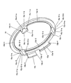
次に、ロックリング10が、ベース部材1に取り付けられる。ロックリング10に設けられ、弾性変形可能な突出片10c−1〜10c−3には、爪部10c−1−a〜10c−3−aと、傾斜面部10c−1−e〜10c−3−eが施されている(図5参照)。一方、ベース部材1には、凹部1q−1〜1q−3と光軸方向にほぼ同一の高さ寸法を有する摺動面1r−1〜1r−3が形成されている。1t、1s−1、1s−2、1u−1、1u−2は、ベース部材1の変形を抑える補強部であり、それらの内で、1s−1、1s−2、1u−1、1u−2は、永久磁石3の光軸中心方向への移動を制限するストッパを兼ねている。
Next, the
ロックリング10の爪部10c−1−a〜10c−3−aをベース部材1の凹部1q−1〜1q−3にそれぞれ合わせて、光軸方向に両部品を近づけていくと、突出片部10c−1〜10c−3が傾斜面部10c−1−e〜10c−3−eに従って光軸側に弾性変形し、さらに、光軸方向に両部品を近づけていくと、突出片部10c−1〜10c−3の弾性変形が開放され(スナップフィット)、組み込みが完了する。この状態では、図7(図6のA−A断面図)に示すように、ベース部材1の凹端面部(光軸を中心とした円弧形状部)1q−1−a〜1q−3−aに、突出片部10c−1〜10c−3の外側端面部10c−1−b〜10c−3−bが係合するとともに、ベース部材1の摺動面部1w−2〜1w−3とロックリング10の摺動面部10d−1〜10d−3(図5参照)がそれぞれ光軸方向に近接し、爪部10c−1−a〜10c−3−aの端面が、摺動面1r−1〜1r−3にほぼ当接している。この状態により、ロックリング10はベース部材1に対して、光軸方向および光軸直交方向への移動が制限され、光軸を回転中心として回転移動することができる。また、ロックリング10には、張り出し片部10aを有しており、その外側端部には歯車部10a−3が施されていて、ステッピングモータ11のピニオン11cと噛合わせて、ステッピングモータ11の駆動力をロックリング10に伝達できるようになっている(図5参照)。
When the
また、ロックリング10の回転移動により、レンズ保持枠5の光軸直交方向への移動を制限したり、この制限を解除したりすることができる。これについてはさらに詳しく説明する。ロックリング10の突出片部10c−1〜10c−3には、カム面部10c−1−c〜10c−3−cと、係止面部(光軸を中心とした円弧面部)10c−1−d〜10c−3−dがある。また、レンズ保持枠5には、係止爪部5k−1〜5k−3の係合面部(略半円柱状で光軸を中心とした円周上に配置されている面部)5k−1−a〜5k−3−aがある(図3参照)。レンズ保持枠5が光軸方向及び光軸直交方向への移動を制限されていない状態(以下、「アンロック領域」という)では、係合面部5k−1−a〜5k−3−aはどこにも当接することはなく、レンズ保持枠5は、穴部5h−1、5h−2の内周面が軸部1i−1、1i−2の外周面に当接することにより、ピッチ方向およびヨー方向の移動が制限される。
Further, the rotational movement of the
一方、アンロック領域から、モータ12を駆動してロックリング10を回転移動(図1において、被写体側から見て反時計周り方向の回転移動)させていくと、係合面部5k−1−a〜5k−3−aがカム面部10c−1−c〜10c−3−cに当接していき、レンズ保持枠5が、カム面部10c−1−c〜10c−3−cの形状に従って移動していく。
On the other hand, when the
さらに、ロックリング10を回転移動させると、係合面部5k−1−a〜5k−3−aは、カム面部10c−1−c〜10c−3−cとの当接状態から係止面部10c−1−d〜10c−3−dとの当接状態に至る。この状態になると、係合面部5k−1−a〜5k−3−aの当接部を結んだ直径と係止面部10c−1−d〜10c−3−dを結んだ直径がほぼ一致するので、レンズ保持枠5は、光軸直交方向への移動が制限される(以下「ロック領域」という)。なお、ロック領域は、特許請求の範囲に記載する第1の領域に対応し、アンロック領域は、特許請求の範囲に記載する第2の領域に対応している。
Further, when the
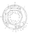
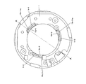
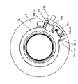
また、ロックリング10のロック、アンロック方向への回転移動は、所定範囲内に制限される。これは、図4に示すように、ベース部材1の突出部1x−1、1x−2とロックリング10の張り出し片10aの両端面10a−1、10a−2において、突出部1x−1の機械端1x−1−aに端面10a−1が当接すると、ロック領域での機械的回転阻止状態(図9の状態)となり、突出部1x−2の機械端1x−2−aに端面10a−2が当接すると、アンロック領域での機械的回転阻止状態(図10の状態)となる。
Further, the rotational movement of the
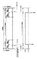
また、ロックリング10は、屈曲片部10bを有しており、前述のフォトインタラプタ12と係合する位置に配置されている(図5参照)。これについて、さらに詳しく説明する。ロックリング10が、ベース部材1に完全に組み込まれた状態では、図13に示すように、屈曲片部10bはフォトインタラプタ12の光軸方向のセンサ位置12C(線12C上にセンサ部がある)と光軸方向にオーバーラップした位置関係になっている。
Further, the
そして、図9と図10が示すように、ロック領域とアンロック領域において、ロックリング10が機械端1x−1−a、1x−2−aに当接した状態では、屈曲片部10bが、フォトインタラプタ12の光軸方向視において、センサ位置12B(線12B上にセンサ部がある)を遮らない構成となっている。
As shown in FIGS. 9 and 10, when the
また、図11と図12が示すように、ロック領域とアンロック領域において、ロックリング10が、機械端1x−1−a、1x−2−aの若干手前に位置する状態では、屈曲片部10bが、フォトインタラプタ12の光軸方向視におけるセンサ位置12B(線12B上にセンサ部がある)を遮るか遮らないかの境界の位置に、屈曲片部10bの端面部10b−1、10b−2が設定されている。
Further, as shown in FIGS. 11 and 12, when the
上記の機械的構成を線図で表すと、図14のようになる。ロック状態とアンロック状態での機械的回転阻止範囲を全範囲として、これは機械的ロック領域、機械的アンロック領域及び機械的ロック・アンロック不完全領域に領域分けする。 The above mechanical structure is represented by a diagram as shown in FIG. The entire range of mechanical rotation prevention in the locked state and unlocked state is divided into a mechanical lock region, a mechanical unlock region, and a mechanical lock / unlock incomplete region.
そして、ロック領域及びアンロック領域の中にそれぞれ、フォトインタラプタ12の光軸方向視におけるセンサ位置12B(線12B上にセンサ部がある)を遮るか遮らないかの境界位置がある。図14では、この境界位置を一点破線で示している。
In each of the lock area and the unlock area, there are boundary positions indicating whether or not to block the
また、フォトインタラプタの出力信号でみると、図14に示すように、境界位置を境としてHigh、Lowの出力信号の変化が得られるようになっている。電気的に見れば、Highのときは電気的ロック・アンロック不完全領域、Lowのときはロックもしくはアンロック領域となっている。 Further, when viewed from the output signal of the photo interrupter, as shown in FIG. 14, changes in the output signals of High and Low are obtained with the boundary position as the boundary. From an electrical viewpoint, when it is High, it is an incompletely locked / unlocked area, and when it is Low, it is a locked or unlocked area.
図14に示すように、電気的ロックもしくはアンロック領域を、機械的ロックもしくはアンロック領域の中に設定しているのは、各部品の機械的な寸法誤差による、ロック・アンロックの判定エラーを回避するためである。例えば、機械的ロック領域と機械的ロック・アンロック不完全領域の境界位置に、フォトインタラプタ12のセンサ位置を合わせたとすると、部品の機械的な寸法誤差により、機械的ロック・アンロック不完全領域であるにもかかわらず、電気的ロック領域と判定されてしまう。この問題を回避するために電気的なロック、アンロック領域の機械端1x−1−a、1x−2−aとその反対側にそれぞれ機械的な余裕範囲を設定にしている(図14参照)。
As shown in FIG. 14, the electrical lock or unlock region is set in the mechanical lock or unlock region because the lock / unlock determination error is caused by the mechanical dimensional error of each part. This is to avoid the problem. For example, if the sensor position of the
なお、本実施例では、ロックリング10の位置検出器として、フォトインタラプタを用いたが、ロックリング10の位置が検出できる他のセンサであってもよい。つまり、ロック、アンロックの機械端1x−1−a、1x−2−aの手前でセンサの出力信号の変化が得られればよく、その出力信号の変化に基づいてロックリングを制御すればよい。
In the present embodiment, the photo interrupter is used as the position detector of the
ところで、上述の構成によれば、コイル6a、6bと永久磁石3と第1のヨーク部材2と第2のヨーク部材7により磁気回路が形成されているので、コイル6aに通電することで、レンズ保持枠5はピッチ方向(図中Y方向)に移動でき、コイル6bに通電することで、レンズ保持枠5はヨー方向(図中X方向)に移動できる。また、コイル6aと6bに通電すると、ピッチ方向とヨー方向の合成した方向に移動できる。そして、それぞれのコイルの電流値を変化させることによって、レンズ保持枠5は、移動範囲内の任意の位置に移動することができる。
By the way, according to the above-described configuration, since the magnetic circuit is formed by the
さらに、レンズ保持枠5には、発光素子15a、15bが取り付けられ、それらの発光光線を受光素子16a、16bで受光できるように構成されているので、レンズ保持枠5のピッチ方向およびヨー方向の位置を検知することができる(15aと16aの組み合わせでヨー方向の位置検知可能、15bと16bの組み合わせでピッチ方向の位置検知可能に構成されている)。
Furthermore, since the light-emitting
なお、上記構成には記載されていないが、コイル6a、6bの端子、発光素子15a、15bの端子はフレキシブルプリント基板等の一端に接続されており、他端は電気回路基板9にコネクタ等で接続されている。また、フレキシブルプリント基板13も、電気回路基板9にコネクタ等で接続されている。さらに、電気回路基板9はレンズCPU301に接続されている。
次に、本発明の振れ補正ユニットの動作を説明する。
Although not described in the above configuration, the terminals of the
Next, the operation of the shake correction unit of the present invention will be described.
まず、先に概説した振れ補正ユニット305のイニシャル動作について、詳細に説明する。
First, the initial operation of the
振れ補正ユニット305のイニシャル動作とは、ロックリング(ロック部材)10を所定の初期状態(初期化位置としての基準位置)に設定するための処理で、ロックリング10をモータ11により駆動している途中で電源が遮断されたり、衝撃等でロックリング10の位置がずれたりして(不意に回転して)、現在のロック状態が、所定基準位置から特定できなくなってしまった時のために、必ず電源投入時に、ロックリング10を駆動して、所定の初期状態(基準位置)に設定する処理である。
The initial operation of the
例えば、本実施例のように、ロックリング10の駆動源として、ステッピングモータ(パルス駆動モータ)を用いた場合、所定の基準位置から目標位置までの駆動パルス数を制御することによって、目標位置に到達させるようにしている。衝撃等でロックリング10が不意に回転するなどして、所定の基準位置からの現在位置(現在位置が基準位置から何パルス目のところか)が分からなくなると、目標位置までの正確なパルス数が算出できなくなる。このために、まず、所定の基準位置を定める動作が必要になる。
For example, when a stepping motor (pulse drive motor) is used as the drive source of the
なお、本実施例においては、所定の初期状態(所定の基準位置)とは、図11の状態(屈曲片部10bが、フォトインタラプタ12の光軸方向から見たセンサ位置12B(線12B上にセンサ部がある)を遮るか遮らないかの境界の位置)よりも所定パルス分(所定時間分)、ロック側の機械端1x−1−a寄りの位置である。
In this embodiment, the predetermined initial state (predetermined reference position) is the state shown in FIG. 11 (the
図11の状態よりも数パルス分(所定時間分)ずらした位置を基準位置とするのは、図11の状態を基準位置としてしまうと、各部品の寸法誤差による機械的なガタにより、屈曲片部10bがフォトインタラプタ12のセンサ部を遮光したり、遮光しなかったりしてフォトインタラプタ12の出力信号が不安定となって、ロック検知が安定せずに、ロックリング10の制御がうまくできなくなる可能性があるからである。例えば、レンズ本体の姿勢が変わると、各部品のガタにより、ロックリング10がそのガタ分ずれて、出力信号のレベルが変化してしまう。この場合、ロックリング10が駆動されていないにもかかわらず、ロック領域と検知されたり、ロック・アンロック不完全領域と検知されたりするからである。そこで、図11の状態よりも所定パルス分(上記ガタの影響を受けない量)だけずらした位置を基準位置(本実施例の場合は、ロック側の機械端1x−1−a寄り)とすることで、上記不具合の発生を防止している。
The position shifted by several pulses (predetermined time) from the state shown in FIG. 11 is used as the reference position. If the state shown in FIG. 11 is used as the reference position, the bent piece is caused by mechanical backlash due to the dimensional error of each part. The
所定パルス数は、通常数パルス程度に設定される。 The predetermined number of pulses is normally set to about several pulses.
図17は、振れ補正ユニットのイニシャル動作のフローチャートである。なお、図14に示すように、機械的ロック・アンロック領域と電気的ロック・アンロック領域とがあるが、以下の説明におけるロック・アンロック領域とは、後者の電気的ロック・アンロック領域を意味する。 FIG. 17 is a flowchart of the initial operation of the shake correction unit. As shown in FIG. 14, there are a mechanical lock / unlock region and an electrical lock / unlock region. The lock / unlock region in the following description refers to the latter electric lock / unlock region. Means.
まず、カメラ本体200の電源スイッチ203がONされ、レンズ本体300に電源の供給が開始(又は、新しい電池を入れられた場合や、カメラ本体200にレンズ本体300が装着された場合など、カメラ本体200とレンズ本体300との間で通信が開始)されると、フォトインタラプタ12の出力信号が、Highレベル(屈曲片部10bがフォトインタラプタのセンサ部を遮光した状態。以下「H」という)かLowレベル(屈曲片部10bがフォトインタラプタのセンサ部を遮光していない状態。以下「L」という)か判定する(S6001)。
First, the
Lの場合は、ロック領域のLなのか、アンロック領域のLなのかが分からないため、以下の処理を行って判別する。すなわち、まず、受光素子16a、16bの出力信号により、レンズ保持枠5の位置を検出する(S6002)。そして、レンズ保持枠5が、所定範囲内(ほぼ光軸中心位置)に位置しているかどうかを判別し(S6003)、所定範囲内に位置していれば、レンズ保持枠5がロック領域にあると判定する。また、所定範囲外に位置しているときは、ロック領域でないと判定する。以上の処理により、ロック領域のLなのか、アンロック領域のLなのかが分かる。
In the case of L, since it is unknown whether L is in the lock area or L in the unlock area, the following processing is performed for determination. That is, first, the position of the
次に、ロック領域のLの場合は、レンズ保持枠5がロック領域のどこに位置しているかがわからないため、まず一旦、アンロック側へロックリング10を駆動(S6004)して、フォトインタラプタ12の出力信号が、LからHになったのを検出(S6005)した後、さらにアンロック側に数パルス(所定時間)駆動して駆動を停止(S6006)する。そして、今度はロック側に駆動(S6007)して、フォトインタラプタ12の出力信号が、HからLになったのを確認(S6008)した後、さらにロック側に数パルス(所定時間)駆動して駆動を停止(S6009)し、振れ補正ユニット305のイニシャル動作を終了する。
Next, in the case of L in the lock area, since it is not known where the
一方、S6001においてHと判定された場合や、S6003でロック領域でないと判定された場合は、ロックリング10をロック側へ駆動する(S6010)。そして、フォトインタラプタ12の出力信号が、HからLになったのを検出(S6008)した後、さらにロック側に数パルス(所定時間)駆動して駆動を停止(S6009)し、振れ補正ユニットのイニシャル動作を終了する。
On the other hand, when it is determined as H in S6001 or when it is determined that it is not a lock region in S6003, the
次にイニシャル動作が行われた後のロックリング10の駆動について説明する。
レンズCPUのロック解除指令により、ロックリング10が、イニシャル動作にて設定した基準位置から、アンロック側へ駆動される。そして、フォトインタラプタ12の出力信号が、HからLになったのを検出後、さらにアンロック側に数パルス(所定時間)駆動して駆動を停止して、ロック解除動作を終了し、振れ補正動作に移行する。その後、レンズCPUのロック駆動指令があった場合は、ロックリング10が、ロック側へ駆動される。
Next, driving of the
The
そして、フォトインタラプタ12の出力信号が、HからLになったのを検出後、さらにロック側に数パルス(所定時間)駆動して駆動を停止(基準位置で停止)して、ロック動作を終了する。
After detecting that the output signal of the
ところで、カメラシステム200およびレンズシステム300では、図16のS5006およびS5017の振れ補正光学系ロック解除動作の途中で、焦点検出、合焦動作、絞り動作が割り込むことがある。このような割り込みが生じたときは、ロックリング10を電気的にロック・アンロック不完全領域に位置した状態で強制的に停止する。この場合の動作を図18のフローチャートを用いて説明する。
Meanwhile, in the
まず、図16のS5006の振れ補正光学系ロック解除動作の途中で、再度焦点検出動作指令、合焦動作指令、絞り動作指令が割り込み動作として、カメラCPU201から発せられると(S7001)、カメラCPU201からの指令を受けたレンズCPU301が、ロックリング10の駆動停止信号をステッピングモータ11に送り、強制的にロックリング10の駆動を停止させる(S7002)。この際に、レンズCPUはフォトインタラプタ12の出力信号の履歴(アンロック開始から割り込みが入るまでの履歴)を記憶しておく。この出力信号の履歴は、停止した位置が、1)『Hを通過しないL』なのか、2)『Hを通過したL』なのか、3)『H』なのかであり、この履歴情報を記憶しておくことである。
First, when the focus detection operation command, the focusing operation command, and the aperture operation command are issued again from the
次に、割り込んできた焦点検出および合焦動作もしくは絞り動作が終了する(S7003)と、SW1がON状態かどうかの判別をする(S7004)。SW1がON状態である(図中Y)と、先ほどのフォトインタラプタ12の出力信号の履歴よりロックリング10がどこに位置しているかを判定する。『Hを通過したL』(2))の場合は、既にアンロック領域にあると判定されるため、ステップS5007の動作へ移行する。
Next, when the interrupted focus detection and focusing operation or aperture operation ends (S7003), it is determined whether or not SW1 is in an ON state (S7004). When SW1 is in the ON state (Y in the figure), it is determined where the
一方、『Hを通過しないL』(1))もしくは『H』(3))の場合はアンロック領域でないと判定されるため、アンロック側へ駆動される(S7006)。
次に、アンロック側への駆動中に、再度焦点検出および合焦動作もしくは絞り動作の割込みがあるかどうかについて監視し、割込みがあった場合はステップS7002へ移行し、割込みがなかった場合は、フォトインタラプタ12の出力信号がHからLになったのを検出(S7008)後、さらにアンロック側に数パルス(所定時間)駆動して駆動を停止(S7009)してアンロック動作を終了し、ステップS5007に移行する。ここで、アンロック側に数パルス(所定時間)駆動する理由は、前述のロックリング10の基準位置を設定する際の考慮と同じで、アンロック領域の停止位置でのフォトインタラプタ12の出力信号を安定させるために行う処理である。
On the other hand, in the case of “L not passing through H” (1)) or “H” (3)), it is determined that the region is not in the unlocked region, and therefore, it is driven to the unlock side (S7006).
Next, during the driving to the unlock side, it is monitored again whether there is an interruption in focus detection and focusing operation or aperture operation. If there is an interruption, the process proceeds to step S7002, and if there is no interruption, After detecting that the output signal of the
SW1がON状態かどうかの判別(S7004)をした際に、SW1がOFF状態である(図中N)場合は、まず振れ補正動作を停止する(S7010)。そして、先ほどのフォトインタラプタ12の出力信号の履歴より、ロックリング10がどこに位置しているかを判定する。『Hを通過しないL』(1))の場合は、既にロック領域であると判定されるため、ステップS5014へ移行する。
一方、『Hを通過したL』(2))もしくは『H』(3))の場合はロック領域でないと判定されるため、ロック側へ駆動される(S7012)。
そして、フォトインタラプタ12の出力信号がHからLになったのを検出(S7013)後、さらにロック側に数パルス(所定時間)駆動して駆動を停止(S7014)してロック動作を終了し、ステップS5014に移行する。
When it is determined whether or not SW1 is in the ON state (S7004), if SW1 is in the OFF state (N in the figure), the shake correction operation is first stopped (S7010). Then, the position of the
On the other hand, in the case of “L passing through H” (2)) or “H” (3)), it is determined that the region is not in the lock region, and therefore, it is driven to the lock side (S7012).
Then, after detecting that the output signal of the
以上説明した本発明の実施例によれば、ロックリング10がベース部材1の機械端に突き当たるのを阻止することができるため、突き当たり時の衝撃音が生じない。また、ロックリング10の駆動を高速化した際に、衝撃力の増大による突き当たり時の歯車部の損傷を回避できる。さらには、ロックリング10の位置検出器を1個で構成しているので、小型の振れ補正光学装置が提供できる。
According to the embodiment of the present invention described above, it is possible to prevent the
なお、本実施例では、ロックリングに屈曲片部を設け、ベース部材にフォトインタラプタ等を設けたが、ロックリングにフォトインタラプタ等を設け、ベース部材に屈曲片部を設けても、同様の機能、効果がある構成となる。
In this embodiment, the bent piece portion provided on the locking ring is provided with the base member to Fotoi Ntaraputa like, provided the photo-interrupter or the like to the locking ring, it is provided with a bent piece on the base member, a similar function It becomes the composition which is effective.
また、ロックリングの駆動源としてステッピングモータ(パルス駆動モータ)を用いたが、他のモータであってもよい。例えば回転角に応じてパルス出力信号が得られるエンコーダ等の回転角検出手段を施したDCモータを使ってもよい。 Further, although the stepping motor (pulse drive motor) is used as the drive source of the lock ring, other motors may be used. For example, a DC motor provided with rotation angle detection means such as an encoder that can obtain a pulse output signal according to the rotation angle may be used.
また、上記エンコーダ等を施さなくても、ロックリングの位置検出回路からの出力信号のトリガ信号(上記本発明の実施例では、LからH、もしくはLからHの切替わり時の信号)が検出されてから一定時間経過後に駆動を停止させるようにすれば、ロックリングを確実にロックまたはアンロック状態で停止させることができ、上述のように、各部品の寸法誤差による機械的なガタにより、ロックリングの屈曲片部がフォトインタラプタ等のセンサ部を遮光したり、遮光しなかったりして位置検出回路の出力信号のL、Hがふらついて、ロックまたはアンロックの検出が安定せずに、ロックリングの制御がうまくできなくなる懸念を回避できる。 Further, the trigger signal of the output signal from the position detection circuit of the lock ring (in the above embodiment of the present invention, the signal at the time of switching from L to H or from L to H) can be detected without applying the encoder or the like If the drive is stopped after a certain period of time has elapsed since then, the lock ring can be reliably stopped in a locked or unlocked state, and as described above, due to mechanical backlash due to dimensional errors of each part, The bent part of the lock ring shields the sensor part such as the photo interrupter or does not shield the light, and the L and H of the output signal of the position detection circuit fluctuate, and the detection of lock or unlock is not stable, The concern that the lock ring cannot be controlled can be avoided.
以上からも明らかなように、本実施例では、カメラに適用した例を述べたが、これに限定されるものではなく、その他の光学機器にも適用することができる。 As is clear from the above, in this embodiment, the example applied to the camera has been described. However, the present invention is not limited to this, and can be applied to other optical devices.
以上説明したように、本実施例によれば、カメラ本体の電源スイッチがONされ、レンズ本体に電源の供給が開始(又は、新しい電池を入れられた場合や、カメラ本体にレンズ本体が装着された場合など、カメラ本体とレンズ本体との間で通信が開始)された場合にでも、ロックリングを機械端に突き当たることなく所定の基準位置(初期状態)に駆動できるので、衝撃音の発生がなく、ロックリングの移動伝達機構の耐久性が向上した振れ補正装置を提供できる。 As described above, according to this embodiment, the power switch of the camera body is turned on, and the power supply to the lens body starts (or when a new battery is inserted, or when the lens body is mounted on the camera body). Even when communication is started between the camera body and the lens body, for example, the lock ring can be driven to a predetermined reference position (initial state) without hitting the machine end, so that an impact sound is generated. In addition, it is possible to provide a shake correction device in which the durability of the movement transmission mechanism of the lock ring is improved.
さらに、本実施例によれば、ロックリングを駆動中に、合焦動作や絞り設定動作などの割込み処理が行われる場合でもロックリングを機械端に突き当たることなく所定の基準位置(初期状態)に駆動できるので、衝撃音の発生がなく、ロックリングの移動伝達機構の耐久性が向上した振れ補正光学装置を提供できる。 Furthermore, according to the present embodiment, even when an interruption process such as a focusing operation or an aperture setting operation is performed while the lock ring is being driven, the lock ring is brought into a predetermined reference position (initial state) without hitting the machine end. Since it can be driven, it is possible to provide a shake correcting optical device that does not generate an impact sound and has improved durability of the movement transmission mechanism of the lock ring.
さらに、本実施例により、衝撃力によって弾性変形量が変化する弾性部材を使うことなく衝撃音を回避できるので、ロックリングの高速駆動時にも充分対応できる構成を持った振れ補正光学装置を提供できる。 Further, according to the present embodiment, it is possible to avoid the impact sound without using an elastic member whose elastic deformation amount is changed by an impact force, and therefore it is possible to provide a shake correcting optical device having a configuration that can sufficiently cope with high speed driving of the lock ring. .
1:ベース部材
2:第1のヨーク部材
3:永久磁石
4:ガイド部材
5:レンズ保持枠
6:コイル
7:第2のヨーク部材
10:ロックリング
11:モータ
12:フォトインタラプタ
15:発光素子
16:受光素子
200:カメラ本体
300:レンズ本体
1: Base member 2: First yoke member 3: Permanent magnet 4: Guide member 5: Lens holding frame 6: Coil 7: Second yoke member 10: Lock ring 11: Motor 12: Photo interrupter 15: Light emitting element 16 : Light receiving element 200: Camera body 300: Lens body
Claims (2)
前記ロック部材が前記第1の領域に位置すると判別したときは、前記アクチュエータを、前記ロック部材が前記第3の領域に移動する方向に、前記第1の信号が前記第2の信号に切り換わり、かつ前記切り換わり時点からの駆動量が第1の駆動量に達するまで駆動し、その後、前記ロック部材が前記第1の領域に移動する方向に、前記第2の信号が前記第1の信号に切り換わり、かつ前記切り換わり時点から前記第1の領域内の初期化位置に達するまで駆動し、
前記ロック部材が前記第2の領域又は前記第3の領域に位置すると判別したときは、前記アクチュエータを前記ロック部材が前記第1の領域に移動する方向に前記第2の信号が前記第1の信号に切り換わり、かつ前記切り換わり時点から前記第1の領域内の初期化位置に達するまで駆動することを特徴とする光学機器。 A lens holding member that holds a lens for correcting image blur by moving in a direction perpendicular to the optical axis of the imaging optical system, and a lock member for locking and unlocking the lens holding member, a first region to lock the lens holding member in the first position, and a second area to unlock the previous SL lens holding member, in the transition region between the first region and the second region A lock member that is movable in a third region, an actuator that drives the lock member, and a first signal that outputs a position signal corresponding to whether or not the lens holding member is in the first position. In the state where the detection means and the lock member are located in either the first region or the second region , the first signal is output, and the lock member is located in the third region. What is the first signal? A second detecting means for outputting a second signal comprising, an optical device and a control means for controlling the actuator,
When it is determined that the lock member is located in the first region, the first signal is switched to the second signal in a direction in which the actuator moves the lock member to the third region. And the second signal is driven in the direction in which the lock member moves to the first region after the drive amount from the switching time point reaches the first drive amount. And driving from the switching time until reaching the initialization position in the first region,
When it is determined that the lock member is located in the second region or the third region, the second signal is transmitted in the direction in which the lock member moves to the first region. optical apparatus and drives switches to signal and from the switched-time until the initialization position of the first region.
前記ロック部材が前記第2の領域又は前記第3の領域に位置すると判別したときは、前記アクチュエータを前記ロック部材が前記第1の領域に移動する方向に前記第2の信号が前記第1の信号に切り換わり、かつ前記切り換わり時点からの駆動量が前記第2の駆動量に達するまで駆動する請求項1に記載の光学機器。 When it is determined that the lock member is located in the first region, the first signal is switched to the second signal in a direction in which the actuator moves the lock member to the third region. And the second signal is driven in the direction in which the lock member moves to the first region after the drive amount from the switching time point reaches the first drive amount. And driving until the driving amount from the switching point reaches a second driving amount corresponding to the driving amount up to the initialization position,
When it is determined that the lock member is located in the second region or the third region, the second signal is transmitted in the direction in which the lock member moves to the first region. 2. The optical apparatus according to claim 1, wherein the optical device is switched until a signal is switched and the driving amount from the switching point reaches the second driving amount.
Priority Applications (2)
| Application Number | Priority Date | Filing Date | Title |
|---|---|---|---|
| JP2004024924A JP4566570B2 (en) | 2004-01-30 | 2004-01-30 | Optical equipment |
| US11/032,647 US7149419B2 (en) | 2004-01-30 | 2005-01-10 | Position control device, image blur correction device, and optical apparatus |
Applications Claiming Priority (1)
| Application Number | Priority Date | Filing Date | Title |
|---|---|---|---|
| JP2004024924A JP4566570B2 (en) | 2004-01-30 | 2004-01-30 | Optical equipment |
Related Child Applications (1)
| Application Number | Title | Priority Date | Filing Date |
|---|---|---|---|
| JP2010074765A Division JP4981945B2 (en) | 2010-03-29 | 2010-03-29 | Optical equipment |
Publications (3)
| Publication Number | Publication Date |
|---|---|
| JP2005215564A JP2005215564A (en) | 2005-08-11 |
| JP2005215564A5 JP2005215564A5 (en) | 2007-03-15 |
| JP4566570B2 true JP4566570B2 (en) | 2010-10-20 |
Family
ID=34805781
Family Applications (1)
| Application Number | Title | Priority Date | Filing Date |
|---|---|---|---|
| JP2004024924A Expired - Fee Related JP4566570B2 (en) | 2004-01-30 | 2004-01-30 | Optical equipment |
Country Status (2)
| Country | Link |
|---|---|
| US (1) | US7149419B2 (en) |
| JP (1) | JP4566570B2 (en) |
Families Citing this family (16)
| Publication number | Priority date | Publication date | Assignee | Title |
|---|---|---|---|---|
| FR2869158A1 (en) * | 2004-04-20 | 2005-10-21 | St Microelectronics Sa | OPTICAL SEMICONDUCTOR HOUSING WITH MEDIUM COMPRESSIBLE ADJUSTMENT |
| US7992579B2 (en) * | 2006-12-29 | 2011-08-09 | Goody Products Inc. | Hair clip with latch mechanism |
| JP5258309B2 (en) * | 2008-01-18 | 2013-08-07 | キヤノン株式会社 | Optical image stabilizer and optical apparatus |
| JP5419360B2 (en) * | 2008-01-28 | 2014-02-19 | キヤノン株式会社 | Optical equipment |
| JP5448629B2 (en) * | 2009-08-06 | 2014-03-19 | キヤノン株式会社 | Optical unit and optical equipment |
| JP5441666B2 (en) * | 2009-12-21 | 2014-03-12 | キヤノン株式会社 | Optical equipment |
| KR101777350B1 (en) * | 2011-03-14 | 2017-09-12 | 삼성전자주식회사 | Position adjusting method and apparatus for optical element |
| JP2013109040A (en) * | 2011-11-17 | 2013-06-06 | Nikon Corp | Shake correction unit, lens barrel, and optical equipment |
| US8682753B2 (en) | 2012-03-24 | 2014-03-25 | Murali S. Kulathungam | System and method to consolidate and update a user's financial account information |
| US9567773B2 (en) | 2014-02-25 | 2017-02-14 | Schlage Lock Company Llc | Electronic lock with selectable power off function |
| KR102255295B1 (en) | 2014-07-24 | 2021-05-25 | 삼성전자주식회사 | Camera module |
| JP6492454B2 (en) * | 2014-08-18 | 2019-04-03 | リコーイメージング株式会社 | Image stabilization apparatus and optical apparatus |
| US9848108B2 (en) * | 2014-08-18 | 2017-12-19 | Ricoh Imaging Company, Ltd. | Image shake correction device and optical apparatus |
| JP7071092B2 (en) * | 2017-11-07 | 2022-05-18 | キヤノン株式会社 | Drives, optics and imaging devices |
| JP7236847B2 (en) * | 2018-11-21 | 2023-03-10 | オリンパス株式会社 | endoscope system |
| CN113196736B (en) * | 2018-12-26 | 2023-03-10 | 华为技术有限公司 | Lens exchange device and portable terminal |
Citations (4)
| Publication number | Priority date | Publication date | Assignee | Title |
|---|---|---|---|---|
| JPH01105229A (en) * | 1987-07-30 | 1989-04-21 | Mita Ind Co Ltd | Lens control method for image forming device |
| JPH0743591A (en) * | 1993-07-28 | 1995-02-14 | Canon Inc | Optical equipment |
| JPH08110553A (en) * | 1994-10-07 | 1996-04-30 | Canon Inc | Camera |
| JPH10254018A (en) * | 1997-03-12 | 1998-09-25 | Canon Inc | Shake correction device |
Family Cites Families (8)
| Publication number | Priority date | Publication date | Assignee | Title |
|---|---|---|---|---|
| JP3044106B2 (en) * | 1991-10-09 | 2000-05-22 | キヤノン株式会社 | Camera with image blur prevention function |
| US5656899A (en) * | 1994-07-18 | 1997-08-12 | Mitsui Mining & Smelting Co., Ltd. | Control apparatus for door lock device |
| JP3530643B2 (en) * | 1995-07-31 | 2004-05-24 | キヤノン株式会社 | Lens barrel and optical equipment using the same |
| JPH10293334A (en) | 1997-04-17 | 1998-11-04 | Canon Inc | Position control device and compensating optical device |
| JPH10142647A (en) | 1996-11-07 | 1998-05-29 | Canon Inc | Image blurring preventing device |
| JPH10293335A (en) | 1997-04-17 | 1998-11-04 | Canon Inc | Position control device and compensating optical device |
| US5974269A (en) * | 1996-11-07 | 1999-10-26 | Canon Kabushiki Kaisha | Image blur preventing apparatus |
| JP2002318402A (en) * | 2001-04-20 | 2002-10-31 | Fuji Photo Optical Co Ltd | Locking device for vibration proof lens for camera, vibration proof adapter and lens device |
-
2004
- 2004-01-30 JP JP2004024924A patent/JP4566570B2/en not_active Expired - Fee Related
-
2005
- 2005-01-10 US US11/032,647 patent/US7149419B2/en active Active
Patent Citations (4)
| Publication number | Priority date | Publication date | Assignee | Title |
|---|---|---|---|---|
| JPH01105229A (en) * | 1987-07-30 | 1989-04-21 | Mita Ind Co Ltd | Lens control method for image forming device |
| JPH0743591A (en) * | 1993-07-28 | 1995-02-14 | Canon Inc | Optical equipment |
| JPH08110553A (en) * | 1994-10-07 | 1996-04-30 | Canon Inc | Camera |
| JPH10254018A (en) * | 1997-03-12 | 1998-09-25 | Canon Inc | Shake correction device |
Also Published As
| Publication number | Publication date |
|---|---|
| US20050169618A1 (en) | 2005-08-04 |
| JP2005215564A (en) | 2005-08-11 |
| US7149419B2 (en) | 2006-12-12 |
Similar Documents
| Publication | Publication Date | Title |
|---|---|---|
| JP4566570B2 (en) | Optical equipment | |
| JP3233493B2 (en) | Image stabilizer | |
| TW201030370A (en) | Image blur correction device, imaging lens unit, and camera unit | |
| US5943169A (en) | Image blur preventing device | |
| EP3561589B1 (en) | Image stabilization apparatus, lens apparatus, and camera system | |
| US7991276B2 (en) | Optical image stabilizer and optical apparatus | |
| JP5794661B2 (en) | Optical equipment | |
| US6738198B2 (en) | Optical-element holding mechanism, image-shake correcting device and optical apparatus | |
| JP3618798B2 (en) | Image blur correction device | |
| US5969886A (en) | Lens barrel and optical apparatus having the same | |
| JP4981945B2 (en) | Optical equipment | |
| US7758261B2 (en) | Light amount adjustment apparatus and image pickup apparatus | |
| JP4416530B2 (en) | Vibration correction apparatus and optical apparatus | |
| JP4416525B2 (en) | Vibration correction apparatus and optical apparatus | |
| JP5714451B2 (en) | Optical image shake correction apparatus and imaging apparatus | |
| JP2897022B2 (en) | Camera malfunction detection device | |
| JPH0743591A (en) | Optical equipment | |
| JPH10228044A (en) | Shake correcting device and changeover device | |
| JP3150224B2 (en) | Image stabilizer | |
| JP2014089264A (en) | Optical vibration-proof device and optical apparatus | |
| JP4456319B2 (en) | camera | |
| JPH11174512A (en) | Image blur correcting device and lens device and camera provided with image blur correcting functions | |
| JP2011164238A5 (en) | ||
| JP2007181368A (en) | Actuator unit | |
| JP2024017220A (en) | Optical equipment with image stabilization device |
Legal Events
| Date | Code | Title | Description |
|---|---|---|---|
| A521 | Request for written amendment filed |
Free format text: JAPANESE INTERMEDIATE CODE: A523 Effective date: 20070126 |
|
| A621 | Written request for application examination |
Free format text: JAPANESE INTERMEDIATE CODE: A621 Effective date: 20070126 |
|
| RD03 | Notification of appointment of power of attorney |
Free format text: JAPANESE INTERMEDIATE CODE: A7423 Effective date: 20081023 |
|
| RD05 | Notification of revocation of power of attorney |
Free format text: JAPANESE INTERMEDIATE CODE: A7425 Effective date: 20081201 |
|
| A131 | Notification of reasons for refusal |
Free format text: JAPANESE INTERMEDIATE CODE: A131 Effective date: 20100202 |
|
| A521 | Request for written amendment filed |
Free format text: JAPANESE INTERMEDIATE CODE: A523 Effective date: 20100329 |
|
| A131 | Notification of reasons for refusal |
Free format text: JAPANESE INTERMEDIATE CODE: A131 Effective date: 20100518 |
|
| A521 | Request for written amendment filed |
Free format text: JAPANESE INTERMEDIATE CODE: A523 Effective date: 20100614 |
|
| TRDD | Decision of grant or rejection written | ||
| A01 | Written decision to grant a patent or to grant a registration (utility model) |
Free format text: JAPANESE INTERMEDIATE CODE: A01 Effective date: 20100803 |
|
| A01 | Written decision to grant a patent or to grant a registration (utility model) |
Free format text: JAPANESE INTERMEDIATE CODE: A01 |
|
| A61 | First payment of annual fees (during grant procedure) |
Free format text: JAPANESE INTERMEDIATE CODE: A61 Effective date: 20100804 |
|
| R150 | Certificate of patent or registration of utility model |
Free format text: JAPANESE INTERMEDIATE CODE: R150 |
|
| FPAY | Renewal fee payment (event date is renewal date of database) |
Free format text: PAYMENT UNTIL: 20130813 Year of fee payment: 3 |
|
| LAPS | Cancellation because of no payment of annual fees |