JP7071092B2 - Drives, optics and imaging devices - Google Patents
Drives, optics and imaging devices Download PDFInfo
- Publication number
- JP7071092B2 JP7071092B2 JP2017214438A JP2017214438A JP7071092B2 JP 7071092 B2 JP7071092 B2 JP 7071092B2 JP 2017214438 A JP2017214438 A JP 2017214438A JP 2017214438 A JP2017214438 A JP 2017214438A JP 7071092 B2 JP7071092 B2 JP 7071092B2
- Authority
- JP
- Japan
- Prior art keywords
- drive amount
- range
- lock
- movable member
- drive
- Prior art date
- Legal status (The legal status is an assumption and is not a legal conclusion. Google has not performed a legal analysis and makes no representation as to the accuracy of the status listed.)
- Expired - Fee Related
Links
Images


Landscapes
- Adjustment Of Camera Lenses (AREA)
- Studio Devices (AREA)
Description
本発明は、駆動装置、光学装置および撮像装置に関する。 The present invention relates to a drive device, an optical device and an image pickup device.
カメラまたはレンズ装置等の光学装置には、手振れ等の光学装置の振れに起因する像ぶれを低減(または補正)するための装置が搭載されている。
像ぶれ低減装置は、例えば、光学装置の振れに応じて光学素子または撮像素子等の素子を光軸方向とは異なる方向(例えば光軸に直交する方向)にシフトさせることで、像ぶれを低減させる。
An optical device such as a camera or a lens device is equipped with a device for reducing (or correcting) image blur caused by shake of the optical device such as camera shake.
The image blur reduction device reduces image blur by, for example, shifting an element such as an optical element or an image pickup element in a direction different from the optical axis direction (for example, a direction orthogonal to the optical axis) according to the shake of the optical device. Let me.
そして、像ぶれ低減装置には、当該素子のシフト動作を行わせない場合や光学装置の電源が切られている場合に、予め定められた位置(例えば、当該素子の中心(光軸)と光学装置の光軸とが一致する位置)に当該素子をロックするロック機構が備えられている。
ロック機構は、像ぶれ補正用素子をロックするロック状態と当該ロックを解除するロック解除状態との間で可動なロック部材と、ロック部材を駆動するアクチュエータとを含んで構成されうる。アクチュエータとしてステッピングモータを用いると、その安定位置での自己保持力(ディテントトルク)により、電力を使用せずにロック状態またはロック解除状態にロック部材を保つことができる。
Then, when the image blur reduction device is not allowed to shift the element or the power of the optical device is turned off, a predetermined position (for example, the center (optical axis) of the element and optics) are used. A locking mechanism for locking the element is provided at a position (position aligned with the optical axis of the device).
The lock mechanism may include a lock member that is movable between a locked state that locks the image blur correction element and an unlocked state that releases the lock, and an actuator that drives the lock member. When a stepping motor is used as an actuator, the lock member can be held in a locked state or an unlocked state without using electric power due to the self-holding force (detent torque) at the stable position.
特許文献1は、ステッピングモータを用いた駆動装置であって、予め定められた初期状態(初期角度)にないロック部材を目標状態まで駆動することのできる駆動装置を提案している。
上述の特許文献1に開示された従来技術では、ロック部材が駆動端に突き当たったのちステッピングモータが空転を繰り返すため、ステッピングモータの脱調による異音が発生しうる。
In the prior art disclosed in
本発明は、例えば、静粛性の点で有利な駆動装置を提供することを目的とする。 It is an object of the present invention to provide, for example, a drive device which is advantageous in terms of quietness.
上記目的を達成するために、本発明の駆動装置は、可動範囲を有するロック部材と、前記ロック部材を駆動する第1駆動部と、像ブレ補正用素子を保持する可動部材と、前記可動部材を駆動する第2駆動部と、前記可動部材の位置を検出する検出部と、制御部とを有し、前記可動部材は、前記可動範囲における一方の端から第1の位置までの第1の範囲において前記ロック部材により移動が制限され、前記制御部は、前記第1の範囲に対応する前記ロック部材の駆動量をΔ2、前記第1の位置から前記第1の範囲外の第2の位置までの前記駆動量Δ2より小さい前記ロック部材の駆動量をΔ1として、所定位置からの前記可動部材の駆動量が前記第2の位置に対応する閾値を超える指令により前記可動部材を駆動させた場合に前記可動部材の駆動量が前記閾値を超えた場合は、前記可動部材の駆動量が前記閾値を超えなくなるまで前記可動部材の可動範囲が小さくなる第1方向に前記駆動量Δ2ずつ前記ロック部材を駆動させた後に、前記第1方向に前記駆動量Δ1だけ前記ロック部材を駆動させることにより、前記第1の範囲内に前記ロック部材を駆動させ、前記指令により前記可動部材を駆動させた場合に前記可動部材の駆動量が前記閾値を超えなかった場合は、前記第1方向とは反対の第2方向に前記駆動量Δ1だけ前記ロック部材を駆動させた後、前記指令により前記可動部材を駆動させた場合に前記可動部材の駆動量が前記閾値を超えなかった場合に、前記第1方向に前記駆動量Δ1だけ前記ロック部材を駆動させることにより、前記第1の範囲内に前記ロック部材を駆動させる制御を行うことを特徴とする。
In order to achieve the above object, the drive device of the present invention includes a lock member having a movable range, a first drive unit for driving the lock member, a movable member for holding an image blur correction element, and the movable member. The movable member has a second driving unit, a detecting unit for detecting the position of the movable member, and a control unit, and the movable member is a first unit from one end to the first position in the movable range. The movement is restricted by the lock member in the range, and the control unit sets the drive amount of the lock member corresponding to the first range to Δ2, and the second position outside the first range from the first position. When the drive amount of the lock member smaller than the drive amount Δ2 up to is set to Δ1 and the movable member is driven by a command in which the drive amount of the movable member from a predetermined position exceeds the threshold value corresponding to the second position. When the drive amount of the movable member exceeds the threshold value, the lock member is driven by the drive amount Δ2 in the first direction in which the movable range of the movable member becomes smaller until the drive amount of the movable member does not exceed the threshold value. The lock member is driven within the first range by driving the lock member in the first direction by the drive amount Δ1, and the movable member is driven by the command. When the drive amount of the movable member does not exceed the threshold value, the lock member is driven by the drive amount Δ1 in the second direction opposite to the first direction, and then the movable member is driven by the command. When the drive amount of the movable member does not exceed the threshold value when driven, the lock member is driven within the first range by driving the lock member by the drive amount Δ1 in the first direction. It is characterized by performing control to drive.
本発明によれば、例えば、静粛性の点で有利な駆動装置を提供することができる。 According to the present invention, for example, it is possible to provide a drive device which is advantageous in terms of quietness.
以下に、本発明の好ましい実施の形態を、添付の図面に基づいて詳細に説明する。 Hereinafter, preferred embodiments of the present invention will be described in detail with reference to the accompanying drawings.
以下、図1~9を参照して、本発明の第1の実施例による駆動装置について説明する。なお、本実施例では、駆動装置として、レンズ装置内に含まれ、光軸と垂直の成分を有する方向に光学系を移動することにより振動による像のぶれを低減させる像ぶれ補正装置(光学装置)を例に説明を行う。 Hereinafter, the driving device according to the first embodiment of the present invention will be described with reference to FIGS. 1 to 9. In this embodiment, as a drive device, an image blur correction device (optical device) included in the lens device and reducing image blur due to vibration by moving the optical system in a direction having a component perpendicular to the optical axis. ) As an example.
図1は、本発明の第1の実施例である像ぶれ補正装置10の構成ブロック図である。
本発明の像ぶれ補正装置10はロック機構を有し、像ぶれ補正用素子のシフト動作を行わせない場合や光学機器の電源が切られている状態で、像ぶれ補正用素子を所定位置(例えば、像ぶれ補正用素子の中心を光学機器の光軸に一致させる位置)に保持する機能を有する。ロックリング(第1可動部材)101はシフトレンズ(第2可動部材)103の可動範囲を制限するロック部材である。詳細については後述する。
ロックリング駆動手段(第1駆動部)102はロックリング101を駆動するためのアクチュエータであり、本実施例ではステッピングモータである。
FIG. 1 is a block diagram of the image
The image
The lock ring driving means (first driving unit) 102 is an actuator for driving the
シフトレンズ103は像ぶれを補正するための光学素子であり、ロックリング101の位置に応じて可動範囲が変化する。
シフトレンズ駆動手段(第2駆動部)104はシフトレンズ103を駆動するためのアクチュエータであり、本実施例ではボイスコイルモータ(VCM)である。
シフトレンズ位置検出手段(検出部)105はシフトレンズ103の位置を検出するための位置検出手段であり、本実施例では光位置センサ(PSD)である。
The
The shift lens driving means (second driving unit) 104 is an actuator for driving the
The shift lens position detecting means (detection unit) 105 is a position detecting means for detecting the position of the
振れ検出手段106は像ぶれ補正装置10の振れを検出するための検出手段であり、本実施例では角速度センサである。
有効無効切替手段107は、像ぶれ補正装置10による像ぶれ補正機能の実行、停止を切り替える切替手段であり、本実施例ではオルタネートのスイッチである。
The shake detecting means 106 is a detecting means for detecting the shake of the image
The valid / invalid switching means 107 is a switching means for switching between execution and stop of the image blur correction function by the image
制御手段(制御部)108は、像ぶれ補正装置10の制御を行う手段であり、シフトレンズ位置検出手段105、振れ検出手段106及び有効無効切替手段107の情報から、ロックリング駆動手段102及びシフトレンズ駆動手段104を駆動する。制御手段108による制御の詳細は後述する。
なお、シフトレンズ駆動手段104、シフトレンズ位置検出手段105、振れ検出手段106は光軸に垂直な平面上において、2軸方向のそれぞれに構成されている。シフトレンズ駆動手段104はシフトレンズ103(レンズ装置)の光軸に直交する方向の成分を有するように、シフトレンズ103を駆動する。
The control means (control unit) 108 is a means for controlling the image
The shift lens driving means 104, the shift lens position detecting means 105, and the runout detecting means 106 are configured in each of the two axial directions on a plane perpendicular to the optical axis. The shift lens driving means 104 drives the
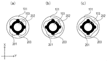
続いて、ロックリング101とシフトレンズ103との関係について、図2及び図3を用いて詳細に説明する。
Subsequently, the relationship between the
図2はロックリング101とシフトレンズ103の構造を示す図である。
ロックリング101はシフトレンズ103の周上に配置され、先述のロックリング駆動手段102により、シフトレンズ103に対して周方向に回転可能である。
ロックリング101の内周の4箇所には、凹部201が形成されており、一方、シフトレンズ103はレンズ保持枠202を有し、レンズ保持枠202の外周の4箇所には、凸部203が形成されている。
FIG. 2 is a diagram showing the structure of the
The
図2(a)に示すように、ロックリング101が、その凹部201がレンズ保持枠202の凸部203に対して異なる位相に位置するように回転した状態では、凸部203がロックリング101の内周面における凹部201が設けられた領域以外の領域に係合する。これにより、シフトレンズ103は中立位置に保持され、そのシフトは阻止される。この状態をロック状態という。
As shown in FIG. 2A, when the
一方、図2(c)に示すように、ロックリング101が、その凹部201内にレンズ保持枠202の凸部203が入り込む位置に回転した状態では、シフトレンズ103のシフトが許容される。この状態でのシフトレンズ103は、像ぶれ補正装置10が像ぶれを適切に行うために必要な可動範囲以上となっている。この状態をアンロック状態という。
また、図2(b)に示すように、シフトレンズ103が中立位置に保持されておらず、かつ像ぶれ補正装置10が像ぶれを適切に行うために必要な可動範囲未満となる状態がある。この状態をロック不安定状態という。
On the other hand, as shown in FIG. 2C, when the
Further, as shown in FIG. 2B, there is a state in which the
なお、ロックリング駆動手段102はステッピングモータで構成されており、ロック状態、アンロック状態を切り替える時のみ電力を使用する。すなわち、ロックリング101を保持する際にはディテントトルクによる安定位置での自己保持力を利用することで、電力を使用せずにロック状態またはアンロック状態でロックリング101を保持することができる。
The lock ring driving means 102 is composed of a stepping motor, and uses electric power only when switching between a locked state and an unlocked state. That is, when the
また、ロック状態からロックリング101を反時計回り方向に駆動すると、ロック不安定状態を経由しアンロック状態へと変化する。ここで、像ぶれ補正装置10には不図示のロックリング規制部があり、ロック状態からロックリング101を時計回りに駆動すると、ロックリング規制部に到達し、ロック不安定状態やアンロック状態へは変化しない構造となっている。同様に、アンロック状態からロックリング101を反時計回りに駆動しても、ロックリング規制部により駆動が制限される。
また、この際、ロックリング規制部に到達した後も駆動のためにモータに通電を続けると、ロックリング駆動手段102のステッピングモータは脱調を繰り返し、通常の駆動では発生しない異音が発生する。
Further, when the
Further, at this time, if the motor is continuously energized for driving even after reaching the lock ring restricting portion, the stepping motor of the lock ring driving means 102 repeats step-out, and an abnormal noise that does not occur in normal driving is generated. ..
図3は、ロックリング101の位置と、ロックリング101の位置にしたがって変化するシフトレンズ103の可動範囲(第2可動範囲)を示すグラフである。
縦軸がシフトレンズ103の可動範囲であり、図2で示すX軸方向におけるシフトレンズ中心からの可動量を示す。
FIG. 3 is a graph showing the position of the
The vertical axis represents the movable range of the
L1は像ぶれ補正装置10が像ぶれを適切に行うために必要な可動範囲であり、すなわちアンロック状態におけるシフトレンズ103の可動範囲の下限である。
L2はロック状態におけるシフトレンズ103の可動範囲である。
L3はロックリング101の位置を推定するための閾値である。ロックリング位置推定処理についての詳細は後述する。
L1 is a movable range required for the image
L2 is the movable range of the
L3 is a threshold value for estimating the position of the
横軸がロックリング101の位置(回転角度)を示す。ロックリング101は回転の可動範囲(第1可動範囲)を有し、駆動端E1はロックリング規制部によるロック位置側の駆動端(一方の端部)であり、駆動端E2はアンロック位置側の駆動端(他方の端部)である。
The horizontal axis indicates the position (rotation angle) of the
位置P1はシフトレンズ103の可動範囲がL2から変化する位置であり、すなわち、シフトレンズ103がロック状態からロック不安定状態へと変化する位置である。
位置P2はシフトレンズ103の可動範囲がL1となる位置であり、すなわち、シフトレンズ103がロック不安定状態からアンロック状態へと変化する位置である。
The position P1 is a position where the movable range of the
The position P2 is a position where the movable range of the
範囲R1(第1領域)はロック位置範囲であり、初期化動作及びロック動作によりロックリング101が駆動される範囲である。また、位置P3は範囲R1のアンロック側の境界である。なお、初期化動作の詳細及びロック動作の詳細については後述する。
The range R1 (first region) is a lock position range, which is a range in which the
なお、位置P3は位置P1よりもロック側である必要がある。これは、ロックリング101の保持にロックリング駆動手段102であるステッピングモータのディテントトルクによる安定位置での自己保持力を利用していることに起因する。すなわち、像ぶれ補正装置10への衝撃等でディテントトルク以上の負荷がかかり、ロックリング101が移動しシフトレンズ103の可動範囲が広がることの無いよう、ロックリング101の位置に余裕を持ってロック状態とするためである。
The position P3 needs to be on the lock side of the position P1. This is due to the fact that the self-holding force at the stable position due to the detent torque of the stepping motor, which is the lock ring driving means 102, is used to hold the
位置P3と位置P1との間の幅は、ステッピングモータのディテントトルクによる安定位置の間隔によるロックリング101の位置の幅以上とすることが望まれるが、加えてステッピングモータのディテントトルクや想定される衝撃等を考慮し設定すると良い。
It is desirable that the width between the position P3 and the position P1 is equal to or larger than the width of the position of the
範囲R2(第4領域)はアンロック位置範囲であり、アンロック動作によりロックリング101が駆動される範囲である。また、位置P4は範囲R2のロック側の境界である。なお、アンロック動作についての詳細については後述する。
なお、位置P4は位置P2と等しいか、よりアンロック側である必要がある。これは、アンロック動作後にシフトレンズ103が、像ぶれ補正装置10が像ぶれを適切に行うために必要な可動範囲を満たす必要があるためである。
The range R2 (fourth area) is the unlock position range, which is the range in which the
The position P4 needs to be equal to or closer to the unlock side than the position P2. This is because the
また、後述するロック動作及びアンロック動作の実現のために、範囲R1と範囲R2の幅は等しくする必要がある。本実施例では範囲R1として設定できる幅が範囲R2として設定できる幅より狭いため、範囲R2の幅を範囲R1の幅と等しくしている。 Further, in order to realize the locking operation and the unlocking operation described later, the widths of the range R1 and the range R2 need to be the same. In this embodiment, since the width that can be set as the range R1 is narrower than the width that can be set as the range R2, the width of the range R2 is made equal to the width of the range R1.
位置P5はロックリング101の位置を推定する境界値(ロック閾値)であり、シフトレンズ103の可動範囲がL3となる位置である。なお、ロックリング位置推定処理についての詳細は後述する。
範囲R3(第2領域)は位置P3と位置P5の間の範囲であり、範囲R4(第3領域)は位置P5と位置P4の間の範囲である。
The position P5 is a boundary value (lock threshold value) for estimating the position of the
The range R3 (second region) is the range between positions P3 and P5, and the range R4 (third region) is the range between positions P5 and P4.
続いて、制御手段108による制御について、図4~9を用いて詳細に説明する。
まずは、制御手段108によるロックリング101の初期化動作について、図4~6を用いて行う。
Subsequently, the control by the control means 108 will be described in detail with reference to FIGS. 4 to 9.
First, the initialization operation of the
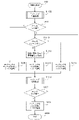
図4は本実施例の制御手段108における初期化動作の動作フローを示すフローチャートである。なお、初期化動作は電源投入時に行われる動作であり、ロックリング101をロックリング規制部に当てることなく、ロックリング101の位置を範囲R1へと移動させるための動作である。
FIG. 4 is a flowchart showing an operation flow of the initialization operation in the control means 108 of this embodiment. The initialization operation is an operation performed when the power is turned on, and is an operation for moving the position of the
S401は処理の開始であり、S402へと進む。
S402ではロックリング位置推定処理を行い、S403へと進む。ロックリング位置推定処理についての詳細は後述する。
S403では推定されたロックリング101が位置P5よりロック側かを判断し、ロック側である場合はS404へ、ロック側でない場合はS405へと進む。
S401 is the start of processing and proceeds to S402.
In S402, the lock ring position estimation process is performed, and the process proceeds to S403. The details of the lock ring position estimation process will be described later.
In S403, it is determined whether the estimated
S404ではロックリング101をアンロック方向(第2方向)に駆動量Δ1だけ駆動し、S406へと進む。なお、駆動量Δ1は範囲R3の幅と等しい値である。
S405ではロックリング101をロック方向(第1方向、第2方向とは反対の方向)に駆動量Δ2だけ駆動し、S406へと進む。なお、駆動量Δ2は範囲R1の幅と等しい値である。
S406ではロックリング位置推定処理を行い、S407へと進む。
In S404, the
In S405, the
In S406, the lock ring position estimation process is performed, and the process proceeds to S407.
S407では推定されたロックリング101が位置P5よりロック側かを判断し、ロック側である場合はS408へ、ロック側でない場合はS405へと進む。
S408ではロックリング101をロック方向に駆動量Δ1だけ駆動し、S409へと進む。
S409は処理の終了である。
In S407, it is determined whether the estimated
In S408, the
S409 is the end of processing.
続いて、図5のフローチャートを用いて、S402、S406におけるロックリング位置推定処理について説明を行う。 Subsequently, the lock ring position estimation process in S402 and S406 will be described with reference to the flowchart of FIG.
S501は処理の開始であり、S502へと進む。
S502ではシフトレンズ駆動手段104によりシフトレンズ103を中心からL3より大きい変位量だけ駆動し、S503へと進む。なお、L3はロックリング101の位置を推定するための閾値であり、ロック状態におけるシフトレンズ103の可動範囲L2より十分大きい値となっている。
S501 is the start of processing, and proceeds to S502.
In S502, the shift lens driving means 104 drives the
S503では、シフトレンズ位置検出手段105により検出されたシフトレンズ103の位置(第1駆動量)がL3よりも内側かどうかを判断し、内側である場合はS504へ、内側でない場合はS505へ進む。シフトレンズ103は、駆動指令がロックリング101で規制されている可動範囲外への駆動指令であっても、実際にはロックリング101の位置によって規制された範囲内でしか駆動することはできない。
In S503, it is determined whether the position (first drive amount) of the
S504では、ロックリング101は位置P5よりもロック側だと判断し、S506へと進む。
S505では、ロックリング101は位置P5よりもロック側でないと判断し、S506へと進む。
S506はシフトレンズ103を中心へと駆動し、S507へと進む。
S507は処理の終了である。
In S504, it is determined that the
In S505, it is determined that the
S506 drives the
S507 is the end of processing.
ここで、範囲R4においては、ロックリング101の位置とシフトレンズ103の可動範囲が一対一に対応する関係を有しているため、シフトレンズ103の最大変位量を検出することで、ロックリングの回転位置を求めることができることになる。
以上のフローにより、シフトレンズ103を駆動させ、その可動範囲からロックリング101の位置を推定することができる。
Here, in the range R4, since the position of the
With the above flow, the
続いて、図6を用いて、初期化動作における効果の詳細を説明する。
図6(a)は初期化動作前のロックリング101の位置が範囲R1内であった場合の、初期化動作を示す図である。
Subsequently, the details of the effect in the initialization operation will be described with reference to FIG.
FIG. 6A is a diagram showing an initialization operation when the position of the
初期化動作前のロックリング101の位置が範囲R1内である場合、位置P5よりもロック側であるため、S403の分岐でS404へと進む。また、S404でアンロック方向に駆動量Δ1だけ駆動した際のロックリング101も位置P5よりロック側となるため、S407の分岐でS408へと進む。
When the position of the
この際、ロックリング101をアンロック方向に駆動量Δ1だけ駆動し、その後ロック方向に駆動量Δ1だけ戻しているので、初期化動作中に駆動端(可動範囲の端部)E1に当たる事はなく、また初期化動作後の位置は初期化動作前の位置と等しく、必ず範囲R1内となる。
At this time, since the
図6(b)は初期化動作前のロックリング101の位置が範囲R2または範囲R4であった場合の、初期化動作を示す図である。
初期化動作前のロックリング101の位置が範囲R2または範囲R4である場合、位置P5よりもロック側ではないため、S403の分岐でS405へと進む。そして、ロックリング101が位置P5よりもロック側となるまでS407の分岐でS405へと戻り、駆動量Δ2だけ駆動する。
FIG. 6B is a diagram showing an initialization operation when the position of the
When the position of the
初期化動作終了時は、S407で位置P5よりもロック側でないと推定されたのちに、S405で駆動量Δ2だけ駆動し、その後S407で位置P5よりもロック側と推定され、S408で駆動量Δ1だけ駆動する。ここで、駆動量Δ1は範囲R3の幅と等しく、駆動量Δ2は範囲R1の幅と等しいため、位置P5よりもロック側でない位置からΔ1+Δ2だけ駆動した際に、駆動端E1に衝突することは無い。また、駆動量Δ1は範囲R3の幅と等しいため、位置P5よりもロック側の位置から駆動量Δ1だけ駆動した際に、必ず位置P3の位置よりロック側へと駆動することが可能である。 At the end of the initialization operation, it is estimated in S407 that it is not on the lock side of the position P5, then it is driven by the drive amount Δ2 in S405, then it is estimated that it is on the lock side of the position P5 in S407, and the drive amount Δ1 is in S408. Only drive. Here, since the drive amount Δ1 is equal to the width of the range R3 and the drive amount Δ2 is equal to the width of the range R1, when driving by Δ1 + Δ2 from a position not on the lock side of the position P5, the collision with the drive end E1 does not occur. There is no. Further, since the drive amount Δ1 is equal to the width of the range R3, when the drive amount Δ1 is driven from the position on the lock side of the position P5, it can always be driven from the position of the position P3 to the lock side.
図6(c)は初期化動作前のロックリング101の位置が範囲R3の内側であった場合の、初期化動作を示す図である。
FIG. 6C is a diagram showing an initialization operation when the position of the
初期化動作前のロックリング101の位置が範囲R3の内側であった場合、位置P5よりもロック側であるため、S403の分岐でS404へと進む。ここで、駆動量Δ1は範囲R3の幅と等しいため、駆動量Δ1だけアンロック方向に駆動すると、必ず位置P5よりもロック側でない位置に移動する。その後、S407で位置P5よりもロック側でないと推定されたのちに、S405で駆動量Δ2だけ駆動し、その後S407で位置P5よりもロック側と推定され、S408で駆動量Δ1だけ駆動する。ここで、駆動量Δ1は範囲R3の幅と等しく、駆動量Δ2は範囲R1の幅と等しいため、位置P5よりもロック側でない位置からΔ1+Δ2だけ駆動した際に、駆動端E1に衝突することは無い。また、駆動量Δ1は範囲R3の幅と等しいため、位置P5よりもロック側の位置から駆動量Δ1だけ駆動した際に、必ず位置P3の位置よりロック側へと駆動することが可能である。
When the position of the
以上説明したとおり、ロックリング101の初期化動作前の位置がいずれの場合であっても、駆動端E1に衝突することなく、必ず範囲R1に収めることができる。
As described above, regardless of the position of the
続いて、図7を用いて、初期化動作後の通常動作におけるアンロック動作について詳細に説明を行う。
図7はアンロック動作の動作フローを示すフローチャートである。
Subsequently, with reference to FIG. 7, the unlocking operation in the normal operation after the initialization operation will be described in detail.
FIG. 7 is a flowchart showing an operation flow of the unlock operation.
S701は処理の開始であり、S702へと進む。なお、処理の開始は初期化動作ののち、有効無効切替手段107により像ぶれ補正動作の有効が指示された時である。
S702ではシフトレンズ103を中心へと駆動し、S703へと進む。
S703ではロックリング101をアンロック方向に駆動量Δ3だけ駆動し、S704へと進む。
S704は処理の終了である。
S701 is the start of processing and proceeds to S702. The process is started when the valid / invalid switching means 107 is instructed to enable the image blur correction operation after the initialization operation.
In S702, the
In S703, the
S704 is the end of processing.
ここで、駆動量Δ3について説明を行う。
駆動量Δ3は、範囲R1に位置しているロックリング101を、駆動端E2に衝突させることなく範囲R2に収めるための駆動量であり、範囲R1の幅と範囲R3の幅と範囲R4の幅を加算した値である。
Here, the drive amount Δ3 will be described.
The drive amount Δ3 is a drive amount for fitting the
先述の初期化動作においてロックリング101は必ず範囲R1に位置していることが保証されているため、オープンループで駆動量Δ3だけ駆動することで、必ず範囲R2に収めることができる。また、範囲R2は範囲R1と等しい範囲としているので、範囲R1の位置から駆動量Δ3だけアンロック方向に駆動しても、駆動端E2に衝突することはない。
なお、通常動作におけるアンロック動作後に、像ぶれ補正装置10による像ぶれ補正を行うが、像ぶれ補正処理については本発明に直接の関係が無いため、説明を省略する。
Since it is guaranteed that the
After the unlocking operation in the normal operation, the image
続いて、図8を用いて、初期化動作後の通常動作におけるロック動作について詳細に説明を行う。 Subsequently, with reference to FIG. 8, the locking operation in the normal operation after the initialization operation will be described in detail.
ロック動作において、アンロック動作時に駆動させた駆動量Δ3と同じ量だけロック方向に駆動すると、通常時は範囲R1に収まるはずである。しかし、アンロック動作と異なり、ロック動作においてはステッピングモータの脱調が発生し、指定した駆動量だけロックリング101が移動することを保証できない。具体的には、ロック動作中にシフトレンズ103が振動等により中心から動いてしまうと、レンズ保持枠202の凸部203とロックリング101の凹部201の縁が干渉し、ロックリング駆動手段102であるステッピングモータが脱調してしまうことがある。もしステッピングモータが脱調してしまうと、指定した駆動量よりも実際の移動量が少なくなり、ロック動作後にロックリング101が範囲R1に位置することを保証できない。
そのため、以下説明するフローを用いてロック動作を行うことで、駆動端E1に衝突することなく範囲R1に駆動することができる。
In the lock operation, if the drive amount is driven in the lock direction by the same amount as the drive amount Δ3 driven during the unlock operation, it should normally fall within the range R1. However, unlike the unlock operation, stepping motor step-out occurs in the lock operation, and it cannot be guaranteed that the
Therefore, by performing the locking operation using the flow described below, the vehicle can be driven into the range R1 without colliding with the drive end E1.
図8はロック動作の動作フローを示すフローチャートである。なお、図4と同じ処理については同符号を符し、説明を省略する。 FIG. 8 is a flowchart showing an operation flow of the lock operation. The same processing as in FIG. 4 is designated by the same reference numerals, and the description thereof will be omitted.
S801は処理の開始であり、S802へと進む。なお、処理の開始は有効無効切替手段107により像ぶれ補正動作の無効が指示された時である。
S802ではシフトレンズ103を中心へと駆動し、S803へと進む。
S803ではロックリング101をロック方向に駆動量Δ4だけ駆動し、S406へと進む。
S406~S409は図4と同等の処理であり、説明を省略する。
S801 is the start of processing, and proceeds to S802. The processing is started when the valid / invalid switching means 107 is instructed to invalidate the image blur correction operation.
In S802, the
In S803, the
S406 to S409 are the same processes as those in FIG. 4, and the description thereof will be omitted.
ここで、駆動量Δ4について説明を行う。
駆動量Δ4は、ロックリング位置推定処理を行う位置まで駆動する駆動量であり、範囲R2の幅と範囲R4の幅を加算した値である。
Here, the drive amount Δ4 will be described.
The drive amount Δ4 is a drive amount for driving to a position where the lock ring position estimation process is performed, and is a value obtained by adding the width of the range R2 and the width of the range R4.
続いて、図9を用いて、ロック動作における効果の詳細について説明を行う。
図9(a)は通常時、すなわちロック動作中にステッピングモータの脱調が発生しなかった場合の、ロック動作を示す図である。
Subsequently, the details of the effect in the locking operation will be described with reference to FIG.
FIG. 9A is a diagram showing a locking operation in a normal state, that is, when the stepping motor does not step out during the locking operation.
範囲R2から駆動量Δ4だけ駆動すると必ず位置P5を超え、図8のS407からS408へと進む。この場合、範囲R2からの駆動量はΔ4+Δ1となる。駆動量Δ4は範囲R2の幅と範囲R4の幅を加算した値であり、駆動量Δ1は範囲R3の幅と同じ値であるため、範囲R2からΔ4+Δ1だけ駆動すると必ず位置P3を超え、駆動端E1に衝突することなく範囲R1に駆動することができる。 When the drive amount Δ4 is driven from the range R2, the position P5 is always exceeded, and the process proceeds from S407 to S408 in FIG. In this case, the driving amount from the range R2 is Δ4 + Δ1. The drive amount Δ4 is a value obtained by adding the width of the range R2 and the width of the range R4, and the drive amount Δ1 is the same value as the width of the range R3. It can be driven to the range R1 without colliding with E1.
一方、ロック動作中にステッピングモータの脱調が発生した場合、駆動量Δ4だけ移動させることができず、本来動かすべき位置よりも手前で止まってしまう。その場合の、S406を行う際のロックリング101の停止位置が位置P5よりもロック側の場合は、図9(a)で示す通常時と同様のステップを進む動作となる。この場合、位置P5よりもロック側の位置から駆動量Δ1だけ駆動するため、必ず位置P3よりもロック側の位置に駆動することができる。また、範囲R2からの駆動量は脱調が発生した分、Δ4+Δ1より少なくなっているため、駆動端E1に衝突することなく範囲R1に駆動することができる。
On the other hand, if the stepping motor is out of step during the locking operation, it cannot be moved by the drive amount Δ4 and stops before the position where it should be moved. In that case, when the stop position of the
また、ロック動作中に脱調が発生したことによりS406を行う際のロックリング101の停止位置が位置P5よりもアンロック側となった場合の動作を、図9(b)で示す。この場合、図8のS407からS405へと進み、駆動量Δ2だけロック側に駆動した後、S406へと戻る。
すなわち、脱調が発生して停止した位置からは初期化動作の図6(b)と同様の動作となり、駆動端E1に衝突することなく範囲R1に駆動することができる。
以上説明したとおり、初期化動作後の通常動作におけるアンロック動作、ロック動作においても、駆動端E1に衝突することなく範囲R1に駆動することができる。
Further, FIG. 9B shows an operation when the stop position of the
That is, from the position where the step-out occurs and stops, the operation is the same as that of FIG. 6B of the initialization operation, and the vehicle can be driven to the range R1 without colliding with the drive end E1.
As described above, even in the unlock operation and the lock operation in the normal operation after the initialization operation, the vehicle can be driven to the range R1 without colliding with the drive end E1.
なお、通常動作におけるアンロック動作後に、像ぶれ補正装置10による像ぶれ補正を行うが、像ぶれ補正中に像ぶれを適切に行うために必要な可動範囲を満たしていないと判断した際には、ロックリング101を駆動量Δ2だけアンロック側に駆動しても良い。
After the unlocking operation in the normal operation, the image
具体的には、像ぶれ補正を行うためのシフトレンズ駆動手段104への信号とシフトレンズ位置検出手段105の信号とを比較し、シフトレンズ103が駆動信号に対して追従できていない場合、必要な可動範囲を満たしていないと判断することができる。
Specifically, the signal to the shift lens driving means 104 for performing image blur correction is compared with the signal of the shift lens position detecting means 105, and it is necessary when the
また、通常動作におけるロック動作を初期化動作と同等のフローにて行っても、ロック位置まで駆動することが可能である。しかし、図5で示すロックリング位置推定処理はシフトレンズ103を駆動させるため、映像に影響を与えてしまう。本実施例に記載のロック動作では、図8のS406にてロックリング位置推定処理を行っているが、図9(a)で示す通常時はこの処理を行う時点で位置P5よりもロック側に位置している。すなわち、この時にシフトレンズ103の駆動範囲はL3以下となり、映像への影響を最小限に抑えることができる。
Further, even if the lock operation in the normal operation is performed in the same flow as the initialization operation, it is possible to drive to the lock position. However, since the lock ring position estimation process shown in FIG. 5 drives the
なお、ロックリング101の初期化動作中にロックリング駆動手段102であるステッピングモータが脱調を繰り返し、位置P5よりもロック側に行くことができない場合、図4のS407からS405へと戻るシーケンスを繰り返すこととなる。しかし、この戻るシーケンスにカウンタを設け、一定以上の回数となった場合にはエラー処理に移行しても良い。具体的にはロックリング駆動手段102及びシフトレンズ駆動手段104への電力供給を遮断し、不図示のLED等でユーザへの異常通知を行う。また、撮影への影響を最小限とするために、シフトレンズ駆動手段104への電力供給を遮断せず、シフトレンズ103を中心に保持するようシフトレンズ駆動手段104を制御しても良い。また、ロック動作における図8のS407からS405へと戻るシーケンスにおいても同様である。
If the stepping motor, which is the lock ring driving means 102, repeatedly steps out during the initialization operation of the
以下、図10~図14を参照して、本発明の第2の実施例による制御装置について説明する。なお、本実施例においては、実施例1とは異なる初期化動作を提供する。 Hereinafter, the control device according to the second embodiment of the present invention will be described with reference to FIGS. 10 to 14. In this embodiment, an initialization operation different from that of the first embodiment is provided.
図10は実施例2におけるロックリング101の位置とシフトレンズ103の可動範囲を示すグラフである。
なお、実施例1の図3と同等のものに関しては、同符号を符し説明を省略する。
FIG. 10 is a graph showing the position of the
The same reference numerals as those shown in FIG. 3 of the first embodiment are designated by the same reference numerals, and the description thereof will be omitted.
L3はロックリング101の位置を推定するためのロック側の閾値であり、L4はロックリング101の位置を推定するためのアンロック側の閾値である。ロックリング位置推定処理についての詳細は後述する。
L3 is a threshold value on the lock side for estimating the position of the
位置P5はロックリング101の位置を推定するロック側の境界値であり、シフトレンズ103の可動範囲がL3となる位置である。また、位置P6はロックリング101の位置を推定するアンロック側の境界値(アンロック閾値)であり、シフトレンズ103の可動範囲がL4となる位置である。なお、ロックリング位置推定処理についての詳細は後述する。
The position P5 is a boundary value on the lock side for estimating the position of the
ここで、シフトレンズ103の可動範囲がL3からL4の範囲は、ロックリング101の位置が位置P5から位置P6の範囲で概略推定可能な範囲となる。シフトレンズ103の可動範囲からロックリング101の推定位置を算出する方法については後述する。
Here, the movable range of the
図11は実施例2における像ぶれ補正装置の初期化動作の動作フローを示すフローチャートである。なお、実施例1における図4または図8と同様の処理については同符号を符し、説明を省略する。 FIG. 11 is a flowchart showing an operation flow of the initialization operation of the image blur correction device in the second embodiment. The same processing as in FIG. 4 or FIG. 8 in the first embodiment is designated by the same reference numerals, and the description thereof will be omitted.
S1102では、S402とは異なるロックリング位置推定処理を行い、S403へと進む。本実施例におけるロックリング位置推定処理についての詳細は後述する。
S1110では、推定されたロックリング101が位置P6よりアンロック側かを判断し、アンロック側である場合はS1111へ、アンロック側でない場合はS1112へと進む。
In S1102, the lock ring position estimation process different from that in S402 is performed, and the process proceeds to S403. The details of the lock ring position estimation process in this embodiment will be described later.
In S1110, it is determined from the position P6 whether the estimated
S1111では、ロックリング101をロック方向に駆動量Δ5だけ駆動し、S1106へと進む。なお、駆動量Δ5は位置P6と位置P3との幅と等しい値である。
S1112では、ロックリング101の推定位置Pn(第2駆動量)を元に駆動量Δn(第3駆動量)を算出した後、S1113へと進む。なお、推定位置Pn及び駆動量Δnの算出方法については後述する。
In S1111, the
In S1112, the drive amount Δn (third drive amount) is calculated based on the estimated position Pn (second drive amount) of the
S1113では、ロックリング101をロック方向に駆動量Δnだけ駆動し、S1106へと進む。
S1106は、S1102と同様、S402とは異なるロックリング位置推定処理を行い、S407へと進む。
In S1113, the
Similar to S1102, S1106 performs a lock ring position estimation process different from that of S402, and proceeds to S407.
続いて、図12~図13を用いて実施例2におけるロックリング位置推定処理について、詳細に説明を行う。
図12は実施例2におけるロックリング位置推定処理を示すフローチャートである。なお、実施例1における図5と同様の処理については同符号を符し、説明を省略する。
Subsequently, the lock ring position estimation process in the second embodiment will be described in detail with reference to FIGS. 12 to 13.
FIG. 12 is a flowchart showing the lock ring position estimation process in the second embodiment. The same processing as in FIG. 5 in the first embodiment is designated by the same reference numerals, and the description thereof will be omitted.
S1202では、シフトレンズ103をシフトレンズの駆動端まで駆動し、S503へと進む。なお、シフトレンズの駆動端とはすなわちロックリング101で規制される位置であり、ロックリング101の位置に応じて変化する。そのため、シフトレンズ駆動手段104は、シフトレンズの駆動端を十分超える制御指令を出力する。
In S1202, the
S1208では、シフトレンズ位置検出手段105により検出されたシフトレンズ103の位置(第2駆動量)がL4よりも外側かどうかを判断し、外側である場合はS1209へ、外側でない場合はS1210へ進む。
S1209では、ロックリング101は位置P6よりもアンロック側だと判断し、S506へと進む。
S1210では、シフトレンズ103の駆動量からロックリング101の推定位置Pnを算出し、S506へと進む。
In S1208, it is determined whether or not the position (second drive amount) of the
In S1209, it is determined that the
In S1210, the estimated position Pn of the
S1210で示す推定位置Pnの算出方法について、図13を用いて説明を行う。図13は、シフトレンズ103の可動範囲とロックリング101の推定位置との関係を示すテーブルである。
The calculation method of the estimated position Pn shown in S1210 will be described with reference to FIG. FIG. 13 is a table showing the relationship between the movable range of the
S1202でシフトレンズ103を駆動させた時に、どの位置まで駆動するかによってシフトレンズ103の可動範囲を測定し、その可動範囲から図13に示すテーブルを用いてロックリング101の推定位置を算出する。具体的には、例えばシフトレンズ103の可動範囲がLbより大きくLcより小さい場合、LbとLcの間の位置に応じてテーブルの要素間を直線で近似し、位置Pbと位置Pcの割合から推定位置を算出すれば良い。
When the
なお、図13のテーブルは出荷前に測定を行い決定していて、不図示の記憶部に記憶されている。具体的にはロックリング駆動手段102のステッピングモータをロック状態から1ステップごとに駆動し、その時のシフトレンズ103の可動範囲を測定する。そして、テーブルにあるシフトレンズ103の可動範囲を超えた時点でのステップ数を記憶することで、テーブルの決定を行っている。
The table of FIG. 13 is measured and determined before shipment, and is stored in a storage unit (not shown). Specifically, the stepping motor of the lock ring driving means 102 is driven step by step from the locked state, and the movable range of the
以上により、シフトレンズ103をシフトレンズの駆動端まで駆動し、シフトレンズ103の可動範囲を測定することで、ロックリング101の位置を推定することができる。
As described above, the position of the
続いて、S1112における駆動量Δnの算出方法について説明を行う。
推定位置Pnからロック側の駆動端E1までの駆動量を(E1-Pn)として、初期化動作後の目標位置が範囲R1の中心であることと、S408で駆動量Δ1だけ駆動することを考慮すると、S1113での駆動量Δnは以下の式1で表わされる。
Δn = (E1-Pn)-(R1×1/2)-Δ1 (式1)
すなわち、初期化動作前の推定位置Pnから、駆動量Δnだけ駆動すると、範囲R1の中心から駆動量Δ1だけアンロック側の位置に駆動する。
Subsequently, a method for calculating the drive amount Δn in S1112 will be described.
Taking the drive amount from the estimated position Pn to the drive end E1 on the lock side as (E1-Pn), it is considered that the target position after the initialization operation is the center of the range R1 and that only the drive amount Δ1 is driven in S408. Then, the drive amount Δn in S1113 is expressed by the
Δn = (E1-Pn)-(R1 × 1/2) −Δ1 (Equation 1)
That is, when the drive amount Δn is driven from the estimated position Pn before the initialization operation, the drive amount Δ1 is driven from the center of the range R1 to the unlocked position.
以上のように、シフトレンズ103の可動範囲からロックリング101の初期化動作のための駆動量Δnを算出することができる。
As described above, the drive amount Δn for the initialization operation of the
続いて、実施例2における初期化動作の効果について、図14を用いて説明を行う。
初期化動作前の位置が範囲R1内であった場合、実施例1の図6(a)で示す動作と同様となるため、詳細説明を省略する。
Subsequently, the effect of the initialization operation in the second embodiment will be described with reference to FIG.
When the position before the initialization operation is within the range R1, the operation is the same as the operation shown in FIG. 6A of the first embodiment, and thus detailed description thereof will be omitted.
図14(a)は初期化動作前のロックリング101が位置P5と位置P6の間であった場合の、初期化動作を示す図である。
FIG. 14A is a diagram showing an initialization operation when the
初期化動作前のロックリング101が位置P5と位置P6の間であった場合、位置P5よりロック側でなく、位置P6よりアンロック側でないため、図11においてS403からS1110、S1112へと進む。そして、S1113にてロックリング101をロック方向に駆動量Δnだけ駆動すると、ロックリング101は範囲R1の中心から駆動量Δ1だけアンロック側の位置である位置P7に移動する。位置P7は位置P5よりもロック側であるため、その後のS407で必ずS408へと進み、駆動量Δ1だけ駆動することで、駆動端E1に衝突することなく範囲R1の中心に駆動することができる。
以上により、初期化動作前のロックリング101が位置P5と位置P6の間であった場合について、正しく初期化動作を行うことができる。
When the
As described above, when the
図14(b)は初期化動作前のロックリング101が位置P6よりもアンロック側であった場合の、初期化動作を示す図である。
FIG. 14B is a diagram showing an initialization operation when the
初期化動作前のロックリング101が位置P6よりもアンロック側であった場合、位置P5よりロック側でなく、位置P6よりアンロック側であるため、図11においてS403からS1110、S1111へと進む。そして、S1111にてロックリング101をロック方向に駆動量Δ5だけ駆動する。ここで、駆動量Δ5は位置P6と位置P3との幅と等しい値であるため、駆動量Δ5だけ駆動すると、ロックリング101は、位置P3よりもアンロック側に移動する。
この位置が図14(b)に示すように範囲R3の内側に位置している場合は、S407からS408へと進み、駆動端E1に衝突することなく範囲R1内に移動することができる。
When the
When this position is located inside the range R3 as shown in FIG. 14 (b), it can proceed from S407 to S408 and move into the range R1 without colliding with the drive end E1.
一方、範囲R3の外側、すなわち位置P5よりもアンロック側に位置している場合は、S407からS1110へと戻るため、図14(a)で示すロックリング101が位置P5と位置P6の間であった場合の動作と同等になる。
以上により、初期化動作前のロックリング101が位置P6よりもアンロック側であった場合についても正しく初期化動作を行うことができる。
On the other hand, when the
As described above, even when the
図14(c)は初期化動作前のロックリング101の位置が範囲R3の内側であった場合の、初期化動作を示す図である。
初期化動作前のロックリング101の位置が範囲R3の内側であった場合、位置P5よりロック側であるため、図11においてS403からS404へと進む。
FIG. 14C is a diagram showing an initialization operation when the position of the
When the position of the
ここで、駆動量Δ1は範囲R3の幅と等しいため、駆動量Δ1だけアンロック方向に駆動すると、必ず位置P5よりもロック側でない位置に移動する。その後、S407で位置P5よりもロック側でないと推定されたのちに、S1110へと戻るため、図14(a)で示すロックリング101が位置P5と位置P6の間であった場合の動作と同等になる。
以上により、初期化動作前のロックリング101の位置が範囲R3の内側であった場合についても正しく初期化動作を行うことができる。
Here, since the drive amount Δ1 is equal to the width of the range R3, when the drive amount Δ1 is driven in the unlock direction, the drive amount Δ1 always moves to a position other than the lock side of the position P5. After that, it is presumed that the lock ring side is not on the lock side of the position P5 in S407, and then returns to S1110, which is equivalent to the operation when the
As described above, even when the position of the
以上示した通り、実施例2の初期化動作において、駆動端E1に衝突することなく範囲R1に駆動することができる。なお、初期化動作中にロックリング駆動手段102であるステッピングモータが脱調した場合においても、図11のS407にてS1110へと戻るシーケンスによって、確実に初期化動作を行うことができる。 As shown above, in the initialization operation of the second embodiment, the vehicle can be driven to the range R1 without colliding with the drive end E1. Even if the stepping motor, which is the lock ring driving means 102, is out of step during the initialization operation, the initialization operation can be reliably performed by the sequence of returning to S1110 in S407 of FIG.
また、実施例1では、初期化動作前のロックリング101の位置がアンロック側に位置している場合、図4で示すS407からS405へと戻るフローを幾度か繰り返すことになる。しかし、実施例2ではシフトレンズ103の可動範囲を測定し、ロックリング101の位置を推定することで、駆動量Δn、もしくは駆動量Δ5だけ一気に駆動することにより、実施例1に比べてロックリング位置推定処理の回数を減らすことができる。すなわち、初期化動作の時間を短縮することができる。また、シフトレンズ位置検出手段105によりシフトレンズ103の可動範囲を高精度で検出できる場合、初期化動作によるロックリング101の位置決めを高精度に行うことができる。
Further, in the first embodiment, when the position of the
図13のテーブルを用いてロックリング101の位置を推定する処理において、シフトレンズ可動範囲の位置からテーブルの要素間を直線で近似し算出する方法を用いた。しかし、勿論これに限ることはなく、ロックリング推定位置として範囲R1からより遠い位置Pcを推定位置として算出しても良い。より遠い位置を推定位置として算出した場合、ロックリング推定位置算出の誤算によって駆動端E1に衝突する可能性を排除することができる。また、推定位置が実際の位置より遠く、S1113による駆動量Δnの駆動において位置P5よりロック側とならない場合には、S407からS1110へと遷移し、再度駆動を行うため、確実に範囲R1に収めることができる。
In the process of estimating the position of the
なお、シフトレンズ位置検出手段105によるシフトレンズ103の可動範囲の検出誤差が大きい場合、初期化動作及びロック動作にて駆動端E1に衝突してしまうことが考えられる。そこで、誤差が大きい場合には、誤差量に応じて駆動量Δnや駆動量Δ5を小さくし、本来の目標位置よりも手前で止めたのちに実施例1の方法で範囲R1に駆動させても良い。そうすることで動作時間は増加するが、駆動端E1に衝突することを回避することができる。
If the detection error of the movable range of the
上記実施例で例示した本発明の駆動装置を有する像ぶれ補正装置(光学装置)を有するレンズ装置と、該レンズ装置によって形成された光学像を受ける撮像素子と、を有する撮像装置を構成することによって、本発明の効果を享受する撮像装置を提供することができる。 To configure an image pickup device having a lens device having an image blur correction device (optical device) having the drive device of the present invention exemplified in the above embodiment, and an image pickup element for receiving an optical image formed by the lens device. Therefore, it is possible to provide an image pickup device that enjoys the effects of the present invention.
以上、本発明の好ましい実施形態について説明したが、本発明はこれらの実施形態に限定されず、その要旨の範囲内で種々の変形及び変更が可能である。 Although the preferred embodiments of the present invention have been described above, the present invention is not limited to these embodiments, and various modifications and modifications can be made within the scope of the gist thereof.
101 ・・・・ ロックリング(第1可動部材)
102 ・・・・ ロックリング駆動手段(第1駆動部)
103 ・・・・ シフトレンズ(第2可動部材)
104 ・・・・ シフトレンズ駆動手段(第2駆動部)
105 ・・・・ シフトレンズ位置検出手段(位置検出手段)
108 ・・・・ 制御手段
101 ... Lock ring (first movable member)
102 ... Lock ring drive means (first drive unit)
103 ... Shift lens (second movable member)
104 ... Shift lens drive means (second drive unit)
105 ... Shift lens position detecting means (position detecting means)
108 ... Control means
Claims (9)
前記ロック部材を駆動する第1駆動部と、
像ブレ補正用素子を保持する可動部材と、
前記可動部材を駆動する第2駆動部と、
前記可動部材の位置を検出する検出部と、
制御部とを有し、
前記可動部材は、前記可動範囲における一方の端から第1の位置までの第1の範囲において前記ロック部材により移動が制限され、
前記制御部は、
前記第1の範囲に対応する前記ロック部材の駆動量をΔ2、前記第1の位置から前記第1の範囲外の第2の位置までの前記駆動量Δ2より小さい前記ロック部材の駆動量をΔ1として、所定位置からの前記可動部材の駆動量が前記第2の位置に対応する閾値を超える指令により前記可動部材を駆動させた場合に前記可動部材の駆動量が前記閾値を超えた場合は、前記可動部材の駆動量が前記閾値を超えなくなるまで前記可動部材の可動範囲が小さくなる第1方向に前記駆動量Δ2ずつ前記ロック部材を駆動させた後に、前記第1方向に前記駆動量Δ1だけ前記ロック部材を駆動させることにより、前記第1の範囲内に前記ロック部材を駆動させ、
前記指令により前記可動部材を駆動させた場合に前記可動部材の駆動量が前記閾値を超えなかった場合は、前記第1方向とは反対の第2方向に前記駆動量Δ1だけ前記ロック部材を駆動させた後、前記指令により前記可動部材を駆動させた場合に前記可動部材の駆動量が前記閾値を超えなかった場合に、前記第1方向に前記駆動量Δ1だけ前記ロック部材を駆動させることにより、前記第1の範囲内に前記ロック部材を駆動させる制御を行うことを特徴とする駆動装置。 A lock member with a movable range and
The first drive unit that drives the lock member and
A movable member that holds the image stabilization element,
A second drive unit that drives the movable member,
A detection unit that detects the position of the movable member, and
Has a control unit
The movable member is restricted in movement by the lock member in the first range from one end to the first position in the movable range.
The control unit
The drive amount of the lock member corresponding to the first range is Δ2, and the drive amount of the lock member smaller than the drive amount Δ2 from the first position to the second position outside the first range is Δ1. When the movable member is driven by a command in which the drive amount of the movable member from a predetermined position exceeds the threshold value corresponding to the second position, the drive amount of the movable member exceeds the threshold value. After driving the lock member by the drive amount Δ2 in the first direction in which the movable range of the movable member becomes smaller until the drive amount of the movable member does not exceed the threshold value, only the drive amount Δ1 is driven in the first direction. By driving the lock member, the lock member is driven within the first range.
When the movable member is driven by the command and the drive amount of the movable member does not exceed the threshold value, the lock member is driven by the drive amount Δ1 in the second direction opposite to the first direction. Then, when the movable member is driven by the command and the drive amount of the movable member does not exceed the threshold value, the lock member is driven by the drive amount Δ1 in the first direction. , A driving device characterized in that control for driving the lock member within the first range is performed.
前記ロック部材を駆動する第1駆動部と、
像ブレ補正用素子を保持する可動部材と、
前記可動部材を駆動する第2駆動部と、
前記可動部材の位置を検出する検出部と、
制御部とを有し、
前記可動部材は、前記可動範囲における一方の端から第1の位置までの第1の範囲において前記ロック部材により移動が制限され、
前記制御部は、
前記第1の範囲に対応する前記ロック部材の駆動量をΔ2、前記第1の位置から前記第1の範囲外の第2の位置までの前記駆動量Δ2より小さい前記ロック部材の駆動量をΔ1として、所定位置からの前記可動部材の駆動量が前記第2の位置に対応する第1の閾値を超える指令により前記可動部材を駆動させた場合に前記可動部材の駆動量が前記第1の閾値を超えた場合は、前記第1の閾値を超えた該駆動量に基づいて、前記指令により前記可動部材を再度駆動させた場合の前記可動部材の駆動量が前記第1の閾値と前記第1の位置に対応する第2の閾値との間の駆動量になるようにするための前記可動部材の可動範囲が小さくなる第1方向における前記ロック部材の駆動量を推定し、推定された該駆動量だけ前記ロック部材を駆動させ、前記指令により前記可動部材を駆動した場合に前記可動部材の駆動量が前記第1の閾値を超えなかった場合、前記第1方向に前記駆動量Δ1だけ前記ロック部材を駆動させることにより、前記第1の範囲内に前記ロック部材を駆動させる制御を行うことを特徴とする駆動装置。 A lock member with a movable range and
The first drive unit that drives the lock member and
A movable member that holds the image stabilization element,
A second drive unit that drives the movable member,
A detection unit that detects the position of the movable member, and
Has a control unit
The movable member is restricted in movement by the lock member in the first range from one end to the first position in the movable range.
The control unit
The drive amount of the lock member corresponding to the first range is Δ2, and the drive amount of the lock member smaller than the drive amount Δ2 from the first position to the second position outside the first range is Δ1. When the movable member is driven by a command in which the drive amount of the movable member from a predetermined position exceeds the first threshold value corresponding to the second position, the drive amount of the movable member is the first threshold value. When the above value is exceeded, the driving amount of the movable member when the movable member is driven again by the command is the first threshold value and the first threshold value based on the driving amount exceeding the first threshold value. The drive amount of the lock member in the first direction in which the movable range of the movable member is reduced so as to be the drive amount between the second threshold value corresponding to the position of is estimated, and the estimated drive amount is obtained. When the lock member is driven by an amount and the movable member is driven by the command and the drive amount of the movable member does not exceed the first threshold value, the lock is performed by the drive amount Δ1 in the first direction. A driving device characterized in that the lock member is controlled to be driven within the first range by driving the member.
請求項1乃至3のいずれか1項に記載の駆動装置とを含むことを特徴とする光学装置。 The image stabilization element and
An optical device including the drive device according to any one of claims 1 to 3.
前記第1駆動部は、ステッピングモータを含むことを特徴とする請求項4に記載の光学装置。 The image shake correction element includes a lens and includes a lens.
The optical device according to claim 4, wherein the first drive unit includes a stepping motor.
前記ロック部材は、前記光軸の周りにおいて前記可動部材を囲み、
前記第1駆動部は、前記ロック部材に前記光軸を軸とした回転をさせることを特徴とする請求項5に記載の光学装置。 The direction in which the second driving unit drives the movable member has a component orthogonal to the optical axis of the lens.
The lock member surrounds the movable member around the optical axis.
The optical device according to claim 5, wherein the first drive unit causes the lock member to rotate about the optical axis.
前記光学装置により形成された像を受ける撮像素子とを有することを特徴とする撮像装置。 The optical device according to any one of claims 4 to 7.
An image pickup device comprising an image pickup device that receives an image formed by the optical device.
Priority Applications (1)
| Application Number | Priority Date | Filing Date | Title |
|---|---|---|---|
| JP2017214438A JP7071092B2 (en) | 2017-11-07 | 2017-11-07 | Drives, optics and imaging devices |
Applications Claiming Priority (1)
| Application Number | Priority Date | Filing Date | Title |
|---|---|---|---|
| JP2017214438A JP7071092B2 (en) | 2017-11-07 | 2017-11-07 | Drives, optics and imaging devices |
Publications (3)
| Publication Number | Publication Date |
|---|---|
| JP2019086647A JP2019086647A (en) | 2019-06-06 |
| JP2019086647A5 JP2019086647A5 (en) | 2020-12-17 |
| JP7071092B2 true JP7071092B2 (en) | 2022-05-18 |
Family
ID=66762963
Family Applications (1)
| Application Number | Title | Priority Date | Filing Date |
|---|---|---|---|
| JP2017214438A Expired - Fee Related JP7071092B2 (en) | 2017-11-07 | 2017-11-07 | Drives, optics and imaging devices |
Country Status (1)
| Country | Link |
|---|---|
| JP (1) | JP7071092B2 (en) |
Families Citing this family (1)
| Publication number | Priority date | Publication date | Assignee | Title |
|---|---|---|---|---|
| CN115542645A (en) * | 2022-09-30 | 2022-12-30 | 苏州佳世达光电有限公司 | Exchangeable lens adaptive control compensation system and method |
Citations (4)
| Publication number | Priority date | Publication date | Assignee | Title |
|---|---|---|---|---|
| JP2005215564A (en) | 2004-01-30 | 2005-08-11 | Canon Inc | Position control device, image blur correction device, and optical apparatus |
| JP2009116033A (en) | 2007-11-06 | 2009-05-28 | Nikon Corp | Blur correction device and optical apparatus |
| US20160070152A1 (en) | 2014-09-05 | 2016-03-10 | Samsung Electronics Co., Ltd. | Optical Image Stabilizing Apparatus and Photographing Apparatus Having the Same |
| JP2016042145A (en) | 2014-08-18 | 2016-03-31 | リコーイメージング株式会社 | Image stabilization apparatus and optical apparatus |
Family Cites Families (1)
| Publication number | Priority date | Publication date | Assignee | Title |
|---|---|---|---|---|
| JPH10293335A (en) * | 1997-04-17 | 1998-11-04 | Canon Inc | Position control device and correction optical device |
-
2017
- 2017-11-07 JP JP2017214438A patent/JP7071092B2/en not_active Expired - Fee Related
Patent Citations (4)
| Publication number | Priority date | Publication date | Assignee | Title |
|---|---|---|---|---|
| JP2005215564A (en) | 2004-01-30 | 2005-08-11 | Canon Inc | Position control device, image blur correction device, and optical apparatus |
| JP2009116033A (en) | 2007-11-06 | 2009-05-28 | Nikon Corp | Blur correction device and optical apparatus |
| JP2016042145A (en) | 2014-08-18 | 2016-03-31 | リコーイメージング株式会社 | Image stabilization apparatus and optical apparatus |
| US20160070152A1 (en) | 2014-09-05 | 2016-03-10 | Samsung Electronics Co., Ltd. | Optical Image Stabilizing Apparatus and Photographing Apparatus Having the Same |
Also Published As
| Publication number | Publication date |
|---|---|
| JP2019086647A (en) | 2019-06-06 |
Similar Documents
| Publication | Publication Date | Title |
|---|---|---|
| JPH05100280A (en) | Vibration-proof camera | |
| JP7071092B2 (en) | Drives, optics and imaging devices | |
| US7149419B2 (en) | Position control device, image blur correction device, and optical apparatus | |
| US9024567B2 (en) | Driving apparatus, camera platform apparatus and lens apparatus including the driving apparatus, and driving method of controlling the driving apparatus | |
| US8503115B2 (en) | Lens drive control device and image pickup device | |
| JP2022010910A (en) | Control system and control method | |
| US11825199B2 (en) | Driving device capable of properly restricting translational movement and rotational movement, image capturing apparatus, and method of controlling driving device | |
| JP4228715B2 (en) | Blur correction device and lens barrel | |
| JP5350029B2 (en) | Optical equipment | |
| JP4747523B2 (en) | Imaging device and zoom lens control method for imaging device | |
| JP4423721B2 (en) | Image blur prevention device | |
| JP2016073174A (en) | Stepping motor driving device, optical equipment and stepping motor driving program | |
| JP4649938B2 (en) | Blur correction device, lens barrel, camera system | |
| JP6700801B2 (en) | Lens barrel and imaging device | |
| JP5293118B2 (en) | Control device | |
| US20260042479A1 (en) | Steering column adjusting device and steering column adjusting method | |
| US20240126044A1 (en) | Control apparatus, rotationally driving apparatus, control method, and storage medium | |
| KR101402207B1 (en) | Device for transferring lens and photographing apparatus comprising the same | |
| JP2020134794A (en) | Lens device | |
| JP4529425B2 (en) | Blur correction device | |
| JP2020144257A (en) | Observation optical system | |
| KR102423705B1 (en) | The Apparatus For Direction Angle Memory Of Side Mirror | |
| JP7721295B2 (en) | Lens device, imaging device, lens device control method, and program | |
| JP5159287B2 (en) | Image shake correction apparatus, imaging apparatus, and image shake correction apparatus control method | |
| JP2018132694A (en) | Image blur correction apparatus and lens apparatus including the same |
Legal Events
| Date | Code | Title | Description |
|---|---|---|---|
| RD05 | Notification of revocation of power of attorney |
Free format text: JAPANESE INTERMEDIATE CODE: A7425 Effective date: 20171214 |
|
| RD04 | Notification of resignation of power of attorney |
Free format text: JAPANESE INTERMEDIATE CODE: A7424 Effective date: 20180126 |
|
| A521 | Request for written amendment filed |
Free format text: JAPANESE INTERMEDIATE CODE: A523 Effective date: 20201105 |
|
| A621 | Written request for application examination |
Free format text: JAPANESE INTERMEDIATE CODE: A621 Effective date: 20201105 |
|
| A977 | Report on retrieval |
Free format text: JAPANESE INTERMEDIATE CODE: A971007 Effective date: 20210831 |
|
| A131 | Notification of reasons for refusal |
Free format text: JAPANESE INTERMEDIATE CODE: A131 Effective date: 20211005 |
|
| A521 | Request for written amendment filed |
Free format text: JAPANESE INTERMEDIATE CODE: A523 Effective date: 20211206 |
|
| A131 | Notification of reasons for refusal |
Free format text: JAPANESE INTERMEDIATE CODE: A131 Effective date: 20220208 |
|
| A521 | Request for written amendment filed |
Free format text: JAPANESE INTERMEDIATE CODE: A523 Effective date: 20220323 |
|
| TRDD | Decision of grant or rejection written | ||
| A01 | Written decision to grant a patent or to grant a registration (utility model) |
Free format text: JAPANESE INTERMEDIATE CODE: A01 Effective date: 20220405 |
|
| A61 | First payment of annual fees (during grant procedure) |
Free format text: JAPANESE INTERMEDIATE CODE: A61 Effective date: 20220506 |
|
| R151 | Written notification of patent or utility model registration |
Ref document number: 7071092 Country of ref document: JP Free format text: JAPANESE INTERMEDIATE CODE: R151 |
|
| LAPS | Cancellation because of no payment of annual fees |