JP4649938B2 - Blur correction device, lens barrel, camera system - Google Patents
Blur correction device, lens barrel, camera system Download PDFInfo
- Publication number
- JP4649938B2 JP4649938B2 JP2004298848A JP2004298848A JP4649938B2 JP 4649938 B2 JP4649938 B2 JP 4649938B2 JP 2004298848 A JP2004298848 A JP 2004298848A JP 2004298848 A JP2004298848 A JP 2004298848A JP 4649938 B2 JP4649938 B2 JP 4649938B2
- Authority
- JP
- Japan
- Prior art keywords
- blur correction
- gravity
- optical member
- lens
- drive
- Prior art date
- Legal status (The legal status is an assumption and is not a legal conclusion. Google has not performed a legal analysis and makes no representation as to the accuracy of the status listed.)
- Expired - Fee Related
Links
Images


Landscapes
- Adjustment Of Camera Lenses (AREA)
- Studio Devices (AREA)
Description
本発明は、カメラ、レンズ、ビデオ、双眼鏡等の光学装置でレンズの一部又は全部を動かすことにより像ブレを補正するブレ補正装置、レンズ鏡筒、カメラシステムに関するものである。 The present invention relates to a blur correction device , a lens barrel, and a camera system that correct image blur by moving part or all of a lens with an optical device such as a camera, a lens, a video, and binoculars.
近年、カメラのブレを防止するために、カメラの振れを検知し、カメラの振れに沿って、レンズの一部(ブレ補正レンズ)を動かすことにより、フィルム面上の像ブレを補正するブレ補正装置の技術が確立されつつある。
ブレ補正装置は、ブレ補正レンズを所定範囲内で保持するためのロック機構(電磁ロック機構等)を備えている。ロック機構は、ブレ補正の開始時には、ロックの解除動作を行い、さらに、ブレ補正の終了時には、ロックの開始動作を行う。
In recent years, in order to prevent camera shake, camera shake is detected, and a part of the lens (blur correction lens) is moved along the camera shake to correct image blur on the film surface. Equipment technology is being established.
The shake correction apparatus includes a lock mechanism (such as an electromagnetic lock mechanism) for holding the shake correction lens within a predetermined range. The lock mechanism performs a lock release operation at the start of blur correction, and further performs a lock start operation at the end of the blur correction.
ブレ補正レンズは、ロックの解除動作をしている間(以下、ロック解除時という)及び、ロックの開始動作をしている間(以下、ロック時という)に、所定範囲内で不自然かつ急激に移動する場合がある。このため、ロック解除時及びロック時に、撮影者等がファインダで像を観察すると、不自然かつ急激な像の変化(いわゆる像飛び)が観察されてしまう。 The blur correction lens is unnatural and abrupt within a predetermined range during the unlocking operation (hereinafter referred to as unlocking) and during the locking start operation (hereinafter referred to as locking). May move to. For this reason, when a photographer or the like observes an image with a viewfinder at the time of unlocking or locking, an unnatural and abrupt image change (so-called image skip) is observed.
従来のブレ補正装置については、例えば、ロック解除時に伴って発生する像飛びを防止するブレ補正装置が知られている(例えば、特許文献1参照)。
ロック時に発生する像飛びを防止する方法としては、例えば、ロック時に、光学装置の姿勢に対して重力方向を検出して、ブレ補正レンズを重力方向にゆっくりと下降させる方法が知られている。
As a conventional blur correction device, for example, a blur correction device that prevents image skipping that occurs when unlocking is known (see, for example, Patent Document 1).
As a method for preventing image skipping that occurs at the time of locking, for example, a method is known in which the direction of gravity is detected with respect to the posture of the optical device and the shake correction lens is slowly lowered in the direction of gravity at the time of locking.
しかし、上述したロック時に発生する像飛びを防止する方法は、あらゆる状況下において、像飛びを防止できるとは限らず、以下のような課題があった。
ブレ補正レンズが複数(例えば、4つ)の弾性部材(バネ等)によって支持されている構造のブレ補正装置では、複数のバネの弾性力が互いに異なると、ブレ補正レンズの重量を考慮しない場合でのバネのつりあいの位置(バネの中立位置)と、ブレ補正レンズの近傍に配置された各種部材とブレ補正レンズとが接触しない位置(ロックのためのセンタリング位置:以下、概中央位置という)とが一致しない状況がある。
However, the above-described method for preventing image skipping at the time of locking does not always prevent image skipping under all circumstances, and has the following problems.
In a shake correction device having a structure in which a shake correction lens is supported by a plurality of (for example, four) elastic members (springs, etc.), when the elastic forces of the plurality of springs are different from each other, the weight of the shake correction lens is not considered. The position of the spring balance at the spring (neutral position of the spring) and the position where the various components arranged in the vicinity of the vibration reduction lens and the vibration reduction lens do not contact (centering position for locking: hereinafter referred to as the approximate center position) There are situations where and do not match.
このような状況下において、電気的な制御を停止すると、ブレ補正レンズが弾性部材により非重力方向に動かされる場合がある。この非重力方向へのブレ補正レンズの移動速度は、バネの弾性力に応じて変化するので、ブレ補正レンズの重量が小さく、バネの弾性力が大きい場合には、不自然かつ急激な像飛びが発生してしまう。
本発明の課題は、ロック時に不自然かつ急激な像飛びが発生することを防止するブレ補正装置、レンズ鏡筒、カメラシステムを提供することである。 An object of the present invention is to provide a blur correction device , a lens barrel, and a camera system that prevent an unnatural and abrupt image jump from occurring when locked.
本発明は、以下のような解決手段により、前記課題を解決する。なお、理解を容易にするために、本発明の実施形態に対応する符号を付して説明するが、これに限定されるものではない。すなわち、請求項1の発明は、像ブレを補正するブレ補正光学部材(102)と、前記ブレ補正光学部材(102)を、所定の可動範囲内(−A〜A,−B〜B)を移動するように支持する弾性部材(102a,102b)と、前記ブレ補正光学部材(102)を駆動する駆動部(103)と、前記駆動部(103)の動作を、機械的に係止するロック部(120a,120b)と、重力方向を検出するための重力方向検出部(101a)と、前記弾性部材(102a,102b)から受ける弾性力が前記重力方向に略直交する第1方向で均衡する均衡位置を記憶する記憶部(104)と、前記ロック部(120a,120b)による係止時に、前記均衡位置のうち前記係止時での可動範囲(−a〜a,−b〜b)の境界に接する位置であって、前記重力方向に沿った安定位置((Xs,−b),(a,Ys''))まで、前記ブレ補正光学部材(102)を駆動するように、前記駆動部(103)の動作を制御する駆動制御部(109)とを備えたこと、を特徴とするブレ補正装置である。
請求項2の発明は、像ブレを補正するブレ補正光学部材(102)と、前記ブレ補正光学部材(102)を、所定の可動範囲内(−A〜A,−B〜B)を移動するように支持する弾性部材(102a,102b)と、前記ブレ補正光学部材(102)を駆動する駆動部(103)と、前記駆動部(103)の動作を、機械的に係止するロック部(120a,120b)と、重力方向を検出するための重力方向検出部(101a)と、前記弾性部材(102a,102b)から受ける弾性力が前記重力方向に略直交する第1方向で均衡する均衡位置を算出する均衡位置演算部(105)と、前記ロック部(120a,120b)による係止時に、前記均衡位置のうち前記係止時での可動範囲(−a〜a,−b〜b)の境界に接する位置であって、前記重力方向に沿った安定位置((Xs,−b),(a,Ys''))まで、前記ブレ補正光学部材(102)を駆動するように、前記駆動部(103)の動作を制御する駆動制御部(109)とを備えたこと、こと、を特徴とするブレ補正装置である。
The present invention solves the above problems by the following means. In addition, in order to make an understanding easy, although the code | symbol corresponding to embodiment of this invention is attached | subjected and demonstrated, it is not limited to this. That is, according to the first aspect of the present invention, the blur correction optical member (102) for correcting the image blur and the blur correction optical member (102) are within a predetermined movable range (-A to A, -B to B). An elastic member (102a, 102b) that is supported to move, a drive unit (103) that drives the blur correction optical member (102), and a lock that mechanically locks the operation of the drive unit (103). Part (120a, 120b), a gravity direction detection part (101a) for detecting the direction of gravity, and the elastic force received from the elastic member (102a, 102b) is balanced in a first direction substantially orthogonal to the direction of gravity. When locked by the storage unit (104) for storing the equilibrium position and the lock unit (120a, 120b), the movable range (-a to a, -b to b) of the equilibrium position at the time of the locking is included. Where it touches the border The operation of the drive unit (103) is performed so as to drive the blur correction optical member (102) to a stable position ((Xs, -b), (a, Ys '')) along the gravity direction. The blur correction device includes a drive control unit (109) for controlling the shake correction device.
The invention according to claim 2 moves the blur correction optical member (102) for correcting image blur and the blur correction optical member (102) within a predetermined movable range (-A to A, -B to B). Elastic members (102a, 102b) to be supported in this manner, a drive unit (103) for driving the blur correction optical member (102), and a lock unit (for mechanically locking the operation of the drive unit (103)). 120a, 120b), a gravity direction detector (101a) for detecting the direction of gravity, and an equilibrium position where the elastic force received from the elastic members (102a, 102b) balances in a first direction substantially orthogonal to the direction of gravity. a balanced position calculation unit for calculating the (105), said locking portion (120a, 120b) during engagement by the movable range at the time of the locking of the balanced position of the (-a~a, -b~b) Where it touches the boundary The operation of the drive unit (103) is controlled so as to drive the blur correction optical member (102) to a stable position ((Xs, -b), (a, Ys '')) along the gravity direction. And a drive control unit (109) for providing a shake correction device.
請求項3の発明は、請求項1に記載のブレ補正装置において、前記記憶部は、前記ブレ補正光学部材(102)の前記弾性部材(102a,102b)から受ける弾性力が前記第1方向及び前記重力方向で均衡する中立位置(Xs,Ys)を記憶し、前記駆動制御部(109)は、前記ブレ補正光学部材(102)を前記重力方向に駆動するときに、前記中立位置(Xs,Ys)を経由するように、前記駆動部(103)の動作を制御すること、を特徴とするブレ補正装置である。According to a third aspect of the present invention, in the shake correction apparatus according to the first aspect, the storage unit receives an elastic force received from the elastic member (102a, 102b) of the shake correction optical member (102) in the first direction and The neutral position (Xs, Ys) balanced in the direction of gravity is stored, and the drive control unit (109) moves the neutral position (Xs, Ys) when driving the shake correcting optical member (102) in the direction of gravity. The motion compensation device is characterized in that the operation of the drive unit (103) is controlled so as to pass through Ys).
請求項4の発明は、請求項1から請求項3までのいずれか1項に記載のブレ補正装置において、前記駆動制御部(109)は、前記ブレ補正光学部材(102)の前記弾性部材(102a,102b)から受ける弾性力が前記第1方向及び前記重力方向で均衡する中立位置(Xs,Ys)を演算し、前記ブレ補正光学部材(102)を前記重力方向に駆動するときに、前記中立位置(Xs,Ys)を経由するように、前記駆動部(103)の動作を制御すること、を特徴とするブレ補正装置である。 According to a fourth aspect of the present invention, in the blur correction device according to any one of the first to third aspects, the drive control unit (109) is configured to provide the elastic member (102) of the blur correction optical member (102). 102a, 102b) calculates the neutral position (Xs, Ys) where the elastic force received from the first direction and the gravity direction is balanced, and when the blur correction optical member (102) is driven in the gravity direction, so as to pass through the neutral position (Xs, Ys), to control the operation of the driving unit (103), Ru der blur correction apparatus according to claim.
請求項5の発明は、請求項1から請求項4までのいずれか1項に記載のブレ補正装置において、前記駆動制御部(109)は、前記ロック部(120a,120b)による係止時であって、前記ブレ補正光学部材(102)を前記安定位置((Xs,−b),(a,Ys’’))まで駆動するときに、前記ブレ補正光学部材(102)を、前記第1方向に沿って前記均衡位置まで駆動した後、前記重力方向に駆動するように、前記駆動部(103)の動作を制御すること、を特徴とするブレ補正装置である。
請求項6の発明は、請求項1から請求項5までのいずれか1項に記載のブレ補正装置を備えたこと、を特徴とするレンズ鏡筒である。
請求項7の発明は、請求項1から請求項5までのいずれか1項に記載のブレ補正装置を備えたこと、を特徴とするカメラシステムである。
According to a fifth aspect of the present invention, in the blur correction device according to any one of the first to fourth aspects, the drive control unit (109) is engaged with the lock units (120a, 120b). When the blur correction optical member (102) is driven to the stable position ((Xs, -b), (a, Ys '')), the blur correction optical member (102) is moved to the first position. The motion compensation device is characterized by controlling the operation of the drive unit (103) so as to drive in the direction of gravity after being driven to the equilibrium position along a direction.
A sixth aspect of the present invention is a lens barrel including the blur correction device according to any one of the first to fifth aspects.
According to a seventh aspect of the present invention, there is provided a camera system including the blur correction device according to any one of the first to fifth aspects.
本発明のブレ補正装置は、(1)駆動制御部は、ロック部による係止時に、弾性部材から受ける弾性力が重力方向に略直交する第1方向で均衡する均衡位置のうち、係止時での可動範囲の境界に接する位置であって、重力方向に沿った安定位置まで、ブレ補正光学部材を駆動するので、ロック時に不自然かつ急激な像飛びが発生することを防止することができる。 The blur correction device according to the present invention includes: (1) When the drive control unit is locked, among the equilibrium positions where the elastic force received from the elastic member is balanced in a first direction substantially orthogonal to the gravity direction when locked by the lock unit. Since the blur correction optical member is driven to a position that is in contact with the boundary of the movable range and to a stable position along the direction of gravity, it is possible to prevent unnatural and abrupt image skipping at the time of locking. .
(2)駆動制御部は、ロック部による係止時であって、ブレ補正光学部材を安定位置まで駆動するときに、ブレ補正光学部材を、第1方向に沿って均衡位置まで駆動した後、重力方向に駆動するので、弾性部材の弾性力は第1方向でつり合っており、駆動部の駆動力を小さくできると共に、ブレ補正光学部材を重力方向に沿ってゆっくり駆動することができる。 (2) When the drive control unit is driven by the lock unit and drives the shake correction optical member to the stable position, the drive control unit drives the shake correction optical member to the equilibrium position along the first direction; Since the elastic member is driven in the direction of gravity, the elastic force of the elastic member is balanced in the first direction, so that the driving force of the drive unit can be reduced and the blur correction optical member can be driven slowly along the direction of gravity.
(3)駆動制御部は、ブレ補正光学部材の弾性部材から受ける弾性力が第1方向及び重力方向で均衡する中立位置を演算し、ブレ補正光学部材を重力方向に駆動するときに、中立位置を経由するので、駆動力を小さくできると共に、制御に関するゲイン等を下げるだけでブレ補正光学部材をゆっくり駆動することができる。 (3) The drive control unit calculates a neutral position where the elastic force received from the elastic member of the shake correction optical member is balanced in the first direction and the gravity direction, and drives the shake correction optical member in the gravity direction. Therefore, the driving force can be reduced, and the blur correction optical member can be driven slowly only by reducing the gain related to the control.
以下に図面等を参照して、発明を実施するための最良の形態を、実施例を挙げて説明する。 The best mode for carrying out the invention will be described below with reference to the drawings and the like.
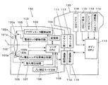
図1(a)は、本発明によるブレ補正装置150の実施例を示すブロック図である。なお、本明細書中、ブレ補正とは、ピッチング方向とヨーイング方向の2方向の補正を行うことをいう。
また、図1(a)では、一方向のブレ補正装置150について説明するが、他方向のブレ補正装置に関しても同様である。ここでは、ブレ補正装置150を中心に、カメラシステム(例えば、一眼レフカメラ)の概要を説明するが、カメラシステムは、ブレ補正装置150を備えた光学装置の一例として示したものである。
FIG. 1A is a block diagram showing an embodiment of a
1A illustrates the
本実施例によるブレ補正装置150は、レンズ鏡筒100と、レンズ鏡筒100が装着されるカメラボディ130等とを備えている。レンズ鏡筒100は、対物側の主レンズ群(不図示)と、ブレ補正レンズ102と、ブレ補正レンズ102を所定の可動範囲内(後述)を移動するように支持するバネ部材102a,102b(ブレ補正レンズ102を懸架する4本の金属製のワイヤ等のバネ部材)と、駆動ユニット120a,120bと、重力方向を検出するための重力方向検出部101aと、光軸と直交する2方向の角速度を検出する角速度センサ101bと、各種制御を行うレンズCPU109と、記憶部104と、アクチュエータ駆動回路103と、電磁ロック駆動回路105と、ブレ補正モードSW108と、振れ検出回路107と、ブレ補正レンズ位置検出回路106と、マウント部111と、通信回路110等とを備えており、レンズCPU109を介して電気的に接続されている。
The
カメラボディ130は、カメラボディ130側の全動作を制御するボディCPU113と、メインSW114と、半押しSW115と、レリーズSW118と、撮影モードSW119と、マウント部117と、通信回路116等とを備えており、ボディCPU113を介して電気的に接続されている。
メインSW114は、カメラボディ130側の電源ON又はOFFの操作を行う。マウント部117は、レンズ鏡筒100とカメラボディ130とを連結するためのカメラマウントである。また、レンズ鏡筒100の電源は、カメラボディ130から供給される。
The
The
レンズCPU109は、通信回路110,116を介して、ボディCPU113と通信を行う。ボディCPU113には、半押しSW115の情報が入力され、半押しSW115のON又はOFFを検知することができる。半押しSW115のONに同期して、ボディCPU113からブレ補正開始コマンドが、また、半押しSW115のOFFに同期して、ブレ補正停止コマンド(ブレ補正の終了指示)がレンズCPU109に送られる。
The
ブレ補正レンズ102は、光軸Lの傾きを補正するように光軸Lと略垂直方向に移動できる。重力方向検出部101aは、例えば、ブレ補正装置150の姿勢に対して重力方向を検出するためのセンサである。なお、重力方向を検出するセンサについては、周知技術であるので、詳細を省略する。また、本明細書中、重力方向とは、物体に重力が作用する1方向を指す。
角速度センサ101bは、例えば、振れを検出する振動ジャイロ型のセンサである。なお、角速度センサ101bについては、振れを検出できるセンサであれば、適宜のセンサ(例えば、加速度センサ)であってもよい。
The
The
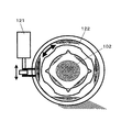
駆動ユニット120a,120bは、例えば、ブレ補正レンズ102を駆動するためのアクチュエータであって、バネ部材102a,102bを介してブレ補正レンズ102と接続されている。駆動ユニット120a,120bは、ブレ補正レンズ102の位置を検出するための不図示の位置センサ(以下、PSDという)を備えている。なお、バネ部材102a,102bは、ブレ補正レンズ102を弾性支持する部材であれば、板バネ、コイルバネ等、適宜の弾性部材を用いることができる。また、バネ部材102a,102bに伸縮方向の位置を調整するアジャスタを設けることもできる。
The
ブレ補正装置150は、ブレ補正レンズ102を所定範囲内で保持するためのロック機構(電磁ロック機構等)を備えている。ここで、ロック機構は、ボディCPU113から送られたブレ補正停止コマンドをレンズCPU109が認識したときに、ロックの開始動作(以下、ロック時という)が行われる(後述)。
The
ブレ補正レンズ位置検出回路106は、駆動ユニット120a,120bに設けられたPSDの出力を、ブレ補正レンズ102の現在位置情報として、レンズCPU109に出力する。振れ検出回路107は、レンズ鏡筒100に生じた振れを検出する回路であって、例えば、角速度センサ101bの出力である角速度を、角速度データ(振れ量)として、レンズCPU109に出力する。
The shake correction lens
記憶部104は、例えば、E2PROMであって、書き換え可能な不揮発性記憶メモリ
である。記憶部104は、例えば、ブレ補正に関する各種調整値と、バネ部材102a,102bの中立位置(ブレ補正レンズ102の重量を考慮しない場合でのバネのつりあいの位置)等とを記憶する。ブレ補正モードSW108は、ブレ補正のモードを切替えるためのブレ補正モードセレクタである。
The
電磁ロック駆動回路105は、ブレ補正レンズ102がバネ部材102a,102bから受ける弾性力が、重力方向検出部101aから検出される重力方向に略直交する方向で均衡する均衡位置(後述)を算出する。また、アクチュエータ駆動回路103によって、ブレ補正レンズ102の近傍に配置された各種部材とブレ補正レンズ102とが接触しない位置(ロックのためのセンタリング位置:以下、概中央位置という)に、ブレ補正レンズ102が駆動されたときに、電磁ロック駆動回路105によって駆動範囲制限部材122(図1(a)、図1(b)参照)が駆動され、この概中央位置にブレ補正レンズ102を係止(電磁ロック)する。なお、均衡位置は、記憶部104に記憶しておいてもよい。
The electromagnetic
レンズCPU109は、記憶部104に記憶された調整値、ブレ補正モードSW108からの出力と、電磁ロック駆動回路105からの出力等とに基づいて、振れ検出回路107からの出力である振れ量を、ブレ補正レンズ102の目標位置情報に変換して、アクチュエータ駆動回路103に出力する。また、レンズCPU109は、ブレ補正レンズ102の現在位置情報を、アクチュエータ駆動回路103に出力する。
The
アクチュエータ駆動回路103は、ブレ補正の動作時に、ブレ補正レンズ102を駆動するためのアクチュエータである駆動ユニット120a,120bを追従制御するための回路である。アクチュエータ駆動回路103は、例えば、ブレ補正レンズ102の目標位置情報と現在位置情報とに基づいて、ブレ補正レンズ102を目標位置に保つようにフィードバック制御する。
The
つぎに、ブレ補正装置150に設けられたロック機構のロック時での動作について説明する。
ロック機構は、例えば、電磁ロックアクチュエータ121及び駆動範囲制限部材122を備え、ロック時に、電磁ロック駆動回路102及びアクチュエータ駆動回路103を介して、レンズCPU109により制御される。
Next, an operation at the time of locking of the lock mechanism provided in the
The locking mechanism includes, for example, an
(重力方向がY軸と略平行である場合でのブレ補正レンズ102の動作について)
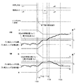
図2は、重力方向がY軸と略平行である場合でのブレ補正装置150の動作を示すタイミングチャートである。
図3は、重力方向がY軸と略平行である場合でのブレ補正レンズ102の位置を示す図である。
ここで、バネ部材102a,102bにより支持されたブレ補正レンズ102の可動範囲は、例えば、ブレ補正可能領域と、ロック時の領域とにそれぞれ区分される。ブレ補正可能領域は、図示のように、X座標(−A〜A),Y座標(−B〜B)に囲まれた領域である。同じく、ロック時の領域は、図示のように、X座標(−a〜a),Y座標(−b〜b)に囲まれた領域である。また、重力方向検出部101aにより検出された重力方向を、−Y方向とする。
(Regarding the operation of the
FIG. 2 is a timing chart showing the operation of the
FIG. 3 is a diagram illustrating the position of the
Here, the movable range of the
まず、ボディCPU113は、半押しSW115の状態を認識する。半押しSW115は、タイミングT100までは、ON状態(ブレ補正の動作時)であって、ロック機構は停止状態である。ボディCPU113は、タイミングT100で、半押しSW115がOFFになったことを認識すると、通信回路116,110を介して、ブレ補正停止コマンドを、レンズCPU109に出力する。
First, the
レンズCPU109は、タイミングT101でブレ補正停止コマンドを受信する。レンズCPU109は、タイミングT101〜T102の間に、ブレ補正レンズ102を概中央位置(Xc,Yc)に移動させるように、アクチュエータ駆動回路103に指示をする。
The
つぎに、レンズCPU109は、ブレ補正レンズ位置検出回路106からの現在位置情報により、ブレ補正レンズ102が概中央位置(Xc,Yc)に移動したことを認識すると、タイミングT102で、電磁ロック駆動回路105に電磁ロックを指示する。電磁ロック駆動回路105は、電磁ロックアクチュエータ121を駆動し、タイミングT102〜T103の間に、ブレ補正レンズ102を概中心位置に一時的にロックする。同時に、駆動範囲制限部材122が移動し、ブレ補正レンズ102の駆動範囲をa〜a’,b〜b’に制限する。
Next, when the
電磁ロック駆動回路105は、ブレ補正レンズ102がバネ部材102a,102bから受ける弾性力が重力方向(−Y方向)と略直交する非重力方向(ここでは、±X方向)で均衡する均衡位置を算出する。均衡位置は、例えば、記憶部104に予め記憶されている中立位置(Xs,Ys)とX座標が同一である位置である。したがって、均衡位置の座標は、(Xs,−b〜b)となる。
The electromagnetic
レンズCPU109は、タイミングT103〜T104の間に、ブレ補正レンズ102を、バネ部材102a,102bからの弾性力に抗して、+X方向に沿って均衡位置まで、ゆっくり(又は、一定速度で)移動させるように、アクチュエータ駆動回路103を制御する。ここで、ブレ補正レンズ102は、タイミングT103〜T104の間に、概中央位置(Xc,Yc)から、均衡位置に含まれる移動位置(Xs,Yc)まで移動する。
The
レンズCPU109は、タイミングT104〜T105の間に、ブレ補正レンズ102を、重力方向(−Y方向)に一定速度で移動させるように、アクチュエータ駆動回路103を制御する。ここで、ブレ補正レンズ102は、タイミングT104〜T105の間で、均衡位置のうちロック時の可動範囲の境界に接する安定位置(Xs,−b)まで移動する。
The
アクチュエータ駆動回路103は、駆動ユニット120a,120bを駆動して、ブレ補正レンズ102を移動位置(Xs,Yc)から安定位置(Xs,−b)まで駆動するときに、バネ部材102a,102bの弾性力は、±X方向でつり合っているので、駆動力を小さくすることができる。
The
重力方向がY軸と略平行である場合には、ブレ補正装置150は、ブレ補正レンズ102を、重力方向と均衡位置とを考慮して、移動位置(Xs,Yc)を経由して、安定位置(Xs,−b)まで移動するので、ロック時に、ブレ補正レンズ102がバネ部材102a,102bの弾性力によって、急激に移動して、ファインダ内で不自然かつ急激な像飛びが発生することを防止できる。
When the gravitational direction is substantially parallel to the Y axis, the
(重力方向がY軸に対して傾いている場合でのブレ補正レンズ4の動作について)
図4は、重力方向がY軸に対して傾いている場合でのブレ補正装置150の動作を示すタイミングチャートである。
図5は、重力方向がY軸に対して傾いている場合でのブレ補正レンズ102の位置を示す図である。
ここでは、上述した重力方向(−Y方向)に対して、反時計回りにθだけずれた方向が重力方向(直線l2の傾き)である点が異なる。
(Regarding the operation of the vibration reduction lens 4 when the gravity direction is inclined with respect to the Y axis)
FIG. 4 is a timing chart showing the operation of the
FIG. 5 is a diagram illustrating the position of the
Here, it differs from the above-described gravity direction (−Y direction) in that the direction shifted counterclockwise by θ is the gravity direction (inclination of the straight line l 2 ).
具体的には、図示のように、重力の方向が−Y方向と角度θをなす直線l2で示される方向であるとする。この場合では、直線l2と同じ傾きで中立位置(Xs,Ys)を通る直線l3と、(Xc,Yc)を通り、直線l2に垂直な傾きを有する直線を直線l1とする。このとき、直線l1と直線l3の交点が移動位置(Xs’,Ys’)となる。 Specifically, as illustrated, it is assumed that the direction of gravity is a direction indicated by a straight line l 2 that forms an angle θ with the −Y direction. In this case, a straight line l 3 passing through the neutral position (Xs, Ys) with the same inclination as the straight line l 2 and a straight line passing through (Xc, Yc) and having a slope perpendicular to the straight line l 2 are defined as a straight line l 1 . At this time, the intersection of the straight line l 1 and the straight line l 3 becomes the movement position (Xs ′, Ys ′).
アクチュエータ駆動回路103は、タイミングT101〜T102の間に、ブレ補正レンズ102を概中央位置(Xc,Yc)に移動する。この概中央位置(Xc,Yc)は、図示のように、直線l2上に位置している。
電磁ロック駆動回路105は、タイミングT102〜T103の間に、ブレ補正レンズ102を概中央位置(Xc,Yc)で電磁ロックする。
The
The electromagnetic
レンズCPU109は、タイミングT103〜T104の間に、ブレ補正レンズ102を、バネ部材102a,102bからの弾性力に抗して、重力方向である直線l2の傾きと略直交方向(直線l1の傾き)に沿って均衡位置(ここでは、直線l2と略平行な直線l3上であって、ロック時の領域内に位置する範囲)まで、ゆっくり(又は、一定速度で)移動させるように、アクチュエータ駆動回路103を制御する。
Lens CPU109, during the timing T103~T104, the
ここで、ブレ補正レンズ102は、タイミングT103〜T104の間に、概中央位置(Xc,Yc)から、均衡位置に含まれる移動位置(Xs’,Ys’)まで移動する。
移動位置(Xs’,Ys’)は、以下の数式で算出される。

The movement position (Xs ′, Ys ′) is calculated by the following mathematical formula.
レンズCPU109は、タイミングT104〜T105の間に、ブレ補正レンズ102を、重力方向(直線l2の傾き)に一定速度で移動させるように、アクチュエータ駆動回路103を制御する。
The
ここで、ブレ補正レンズ102は、タイミングT104〜T105の間で、バネ部材102a,102bの中立位置(Xs,Ys)を経由した後、均衡位置のうちロック時の可動範囲の境界に接する安定位置(a,Ys’’)まで移動する。
安定位置のY座標であるYs’’は、以下の数式で算出される。
![]()
Ys ″ which is the Y coordinate of the stable position is calculated by the following mathematical formula.
![]()
アクチュエータ駆動回路103は、駆動ユニット120a,120bを駆動して、ブレ補正レンズ102を移動位置(Xs’,Ys’)から安定位置(a,Ys’’)まで駆動するときに、バネ部材102a,102bの弾性力は、重力方向と略直交方向(直線l1 の傾き)でつり合っており、さらに、バネ部材102a,102bの中立位置(Xs,Ys)を経由するので、例えば、駆動力を小さくできると共に、制御に関するゲイン等を下げるだけでブレ補正レンズ102をゆっくり駆動することができる。
The
重力方向がY軸に対して傾いている場合には、ブレ補正装置150は、ブレ補正レンズ102を、重力方向と均衡位置とを考慮して、移動位置(Xs’,Ys’)、中立位置(Xs,Ys)を経由して、安定位置(a,Ys’’)まで移動するので、ロック時に、ブレ補正レンズ102がバネ部材102a,102bの弾性力によって、急激に移動して、ファインダ内で不自然かつ急激な像飛びが発生することを防止できる。
When the gravitational direction is inclined with respect to the Y axis, the
(変形例)
以上説明した実施例に限定されることなく、種々の変形や変更が可能であって、それらも本発明の均等の範囲である。
(1)上述した実施例では、ブレ補正レンズ102を、略中央位置(Xc,Yc)から安定位置(Xs,−b)又は(a,Ys’’)まで駆動するときに、移動位置(Xs,Yc)、又は、(Xs’,Ys’)及び中立位置(Xs,Ys)を経由していたが、ブレ補正レンズ102を、安定位置(Xs,−b)又は(a,Ys’’)に直接駆動するようにしてもよい。
具体的には、レンズCPU109は、重力方向及び均衡位置に基づいて安定位置を予め算出して、記憶部104に記憶した後、ロック時に、アクチュエータ駆動回路103を制御して、ブレ補正レンズ102を略中央位置から安定位置に直接駆動するようにすればよい。
(Modification)
The present invention is not limited to the embodiments described above, and various modifications and changes are possible, and these are also within the equivalent scope of the present invention.
(1) In the above-described embodiment, when the
Specifically, the
(2)中立位置(Xs,Ys)は、記憶部104に予め記憶するようにしたが、記憶部104に記憶されている各種調整値に基づいて、レンズCPU109が算出するようにしてもよい。
(3)上述した実施例では、重力方向として、−Y方向と、直線l2の傾きとについて説明したが、これら以外の重力方向であっても、レンズCPU109は、均衡位置のうちロック時の可動範囲の境界に接する安定位置を算出して、ブレ補正レンズ102を重力方向に沿って、安定位置までゆっくり駆動することができる。
(4)上述した実施例では、重力方向検出部101aを用いて重力方向を検出したが、これに限られず、ブレ補正レンズ102を駆動するのに要する力から重力方向を求めてもよい。
(5)上述した実施例では、移動位置(Xs’,Ys’)は、式1、式2で算出する例で説明したが、以下の数式で算出するようにしてもよい。
Xs’=(αβXc−Yc+βXs−Xc)/(α+β)
Ys’=(−αβXc+βYc+αβYs+αYs)/(α+β)
但し、α=(Ys−Yc)/(Xs−Xc)
β=−(Xs−Xc)/(Ys−Yc)
このとき、上述した式3に対応する安定位置のY座標であるYs’’は、以下の数式で算出される。
Ys’’=Ys+{αβ(Xc−Ys)(a−Xs)}/{Xc+Yc−α(Xc−Xs)}
(2) The neutral position (Xs, Ys) is stored in advance in the
(3) In the above-described embodiments, the −Y direction and the inclination of the straight line l 2 have been described as the gravity direction. However, even in the other gravity directions, the
(4) In the above-described embodiment, the gravity direction is detected using the gravity
(5) In the above-described embodiment, the movement position (Xs ′, Ys ′) has been described as an example of calculation using Expression 1 and Expression 2, but may be calculated using the following expression.
Xs ′ = (αβXc−Yc + βXs−Xc) / (α + β)
Ys ′ = (− αβXc + βYc + αβYs + αYs) / (α + β)
Where α = (Ys−Yc) / (Xs−Xc)
β = − (Xs−Xc) / (Ys−Yc)
At this time, Ys ″ which is the Y coordinate of the stable position corresponding to the above-described Expression 3 is calculated by the following expression.
Ys ″ = Ys + {αβ (Xc−Ys) (a−Xs)} / {Xc + Yc−α (Xc−Xs)}
100 レンズ鏡筒
101a 重力方向検出部
101b 角速度センサ
102 ブレ補正レンズ
102a,102b バネ部材
103 アクチュエータ駆動回路
104 記憶部
105 電磁ロック駆動回路
106 ブレ補正レンズ位置検出回路
107 振れ検出回路
108 ブレ補正モードSW
109 レンズCPU
113 ボディCPU
120a,120b 駆動ユニット
121 電磁ロックアクチュエータ
122 駆動範囲制限部材
130 カメラボディ
150 ブレ補正装置
DESCRIPTION OF
109 Lens CPU
113 Body CPU
120a,
Claims (7)
前記ブレ補正光学部材を、所定の可動範囲内を移動するように支持する弾性部材と、
前記ブレ補正光学部材を駆動する駆動部と、
前記駆動部の動作を、機械的に係止するロック部と、
重力方向を検出するための重力方向検出部と、
前記弾性部材から受ける弾性力が前記重力方向に略直交する第1方向で均衡する均衡位置を記憶する記憶部と、
前記ロック部による係止時に、前記均衡位置のうち前記係止時での可動範囲の境界に接する位置であって、前記重力方向に沿った安定位置まで、前記ブレ補正光学部材を駆動するように、前記駆動部の動作を制御する駆動制御部とを備えたこと、
を特徴とするブレ補正装置。 A blur correction optical member for correcting image blur;
An elastic member that supports the blur correction optical member so as to move within a predetermined movable range;
A drive unit for driving the blur correction optical member;
A lock part for mechanically locking the operation of the drive part;
A gravity direction detector for detecting the direction of gravity;
A storage unit for storing an equilibrium position where an elastic force received from the elastic member is balanced in a first direction substantially orthogonal to the direction of gravity;
At the time of locking by the lock portion, the blur correction optical member is driven to a position in contact with the boundary of the movable range at the time of locking among the balanced positions and to a stable position along the gravity direction. A drive control unit for controlling the operation of the drive unit,
A blur correction device characterized by the above.
前記ブレ補正光学部材を、所定の可動範囲内を移動するように支持する弾性部材と、
前記ブレ補正光学部材を駆動する駆動部と、
前記駆動部の動作を、機械的に係止するロック部と、
重力方向を検出するための重力方向検出部と、
前記弾性部材から受ける弾性力が前記重力方向に略直交する第1方向で均衡する均衡位置を算出する均衡位置演算部と、
前記ロック部による係止時に、前記均衡位置のうち前記係止時での可動範囲の境界に接する位置であって、前記重力方向に沿った安定位置まで、前記ブレ補正光学部材を駆動するように、前記駆動部の動作を制御する駆動制御部とを備えたこと、
を特徴とするブレ補正装置。 A blur correction optical member for correcting image blur;
An elastic member that supports the blur correction optical member so as to move within a predetermined movable range;
A drive unit for driving the blur correction optical member;
A lock part for mechanically locking the operation of the drive part;
A gravity direction detector for detecting the direction of gravity;
An equilibrium position calculation unit for calculating an equilibrium position where the elastic force received from the elastic member is balanced in a first direction substantially orthogonal to the direction of gravity;
At the time of locking by the lock portion, the blur correction optical member is driven to a position in contact with the boundary of the movable range at the time of locking among the balanced positions and to a stable position along the gravity direction. A drive control unit for controlling the operation of the drive unit,
A blur correction device characterized by the above.
前記記憶部は、
前記ブレ補正光学部材の前記弾性部材から受ける弾性力が前記第1方向及び前記重力方向で均衡する中立位置を記憶し、
前記駆動制御部は、
前記ブレ補正光学部材を前記重力方向に駆動するときに、前記中立位置を経由するように、前記駆動部の動作を制御すること、
を特徴とするブレ補正装置。 The blur correction device according to claim 1,
The storage unit
Storing a neutral position where the elastic force received from the elastic member of the blur correction optical member is balanced in the first direction and the gravity direction;
The drive control unit
Controlling the operation of the drive unit so as to pass through the neutral position when the blur correction optical member is driven in the gravity direction;
A blur correction device characterized by the above.
前記駆動制御部は、
前記ブレ補正光学部材の前記弾性部材から受ける弾性力が前記第1方向及び前記重力方向で均衡する中立位置を演算し、
前記ブレ補正光学部材を前記重力方向に駆動するときに、前記中立位置を経由するように、前記駆動部の動作を制御すること、
を特徴とするブレ補正装置。 In the blurring correction apparatus according to any one of claims 1 to 3,
The drive control unit
Calculating a neutral position where the elastic force received from the elastic member of the blur correction optical member is balanced in the first direction and the gravitational direction;
Controlling the operation of the drive unit so as to pass through the neutral position when the blur correction optical member is driven in the gravity direction;
A blur correction device characterized by the above.
前記駆動制御部は、
前記ロック部による係止時であって、前記ブレ補正光学部材を前記安定位置まで駆動するときに、前記ブレ補正光学部材を、前記第1方向に沿って前記均衡位置まで駆動した後、前記重力方向に駆動するように、前記駆動部の動作を制御すること、
を特徴とするブレ補正装置。 In the blur correction device according to any one of claims 1 to 4 ,
The drive control unit
At the time of locking by the lock portion, when driving the blur correction optical member to the stable position, the blur correction optical member is driven to the equilibrium position along the first direction, and then the gravity is Controlling the operation of the drive unit to drive in the direction;
A blur correction device characterized by the above.
を特徴とするレンズ鏡筒。 Comprising the blur correction device according to any one of claims 1 to 5 ,
A lens barrel characterized by
を特徴とするカメラシステム。 Comprising the blur correction device according to any one of claims 1 to 5 ,
A camera system characterized by
Priority Applications (1)
| Application Number | Priority Date | Filing Date | Title |
|---|---|---|---|
| JP2004298848A JP4649938B2 (en) | 2003-10-15 | 2004-10-13 | Blur correction device, lens barrel, camera system |
Applications Claiming Priority (2)
| Application Number | Priority Date | Filing Date | Title |
|---|---|---|---|
| JP2003354480 | 2003-10-15 | ||
| JP2004298848A JP4649938B2 (en) | 2003-10-15 | 2004-10-13 | Blur correction device, lens barrel, camera system |
Publications (3)
| Publication Number | Publication Date |
|---|---|
| JP2005202358A JP2005202358A (en) | 2005-07-28 |
| JP2005202358A5 JP2005202358A5 (en) | 2007-11-29 |
| JP4649938B2 true JP4649938B2 (en) | 2011-03-16 |
Family
ID=34828853
Family Applications (1)
| Application Number | Title | Priority Date | Filing Date |
|---|---|---|---|
| JP2004298848A Expired - Fee Related JP4649938B2 (en) | 2003-10-15 | 2004-10-13 | Blur correction device, lens barrel, camera system |
Country Status (1)
| Country | Link |
|---|---|
| JP (1) | JP4649938B2 (en) |
Cited By (1)
| Publication number | Priority date | Publication date | Assignee | Title |
|---|---|---|---|---|
| US9106833B2 (en) | 2012-09-14 | 2015-08-11 | Ricoh Imaging Company, Ltd. | Blur correction apparatus |
Families Citing this family (7)
| Publication number | Priority date | Publication date | Assignee | Title |
|---|---|---|---|---|
| JP2009015072A (en) * | 2007-07-05 | 2009-01-22 | Nikon Corp | Energizing member, optical component and optical apparatus |
| JP2009015048A (en) * | 2007-07-05 | 2009-01-22 | Nikon Corp | Camera |
| JP5183135B2 (en) | 2007-09-21 | 2013-04-17 | キヤノン株式会社 | Interchangeable lenses and optical equipment |
| JP5590904B2 (en) * | 2010-02-08 | 2014-09-17 | キヤノン株式会社 | Optical equipment |
| CN109478001B (en) * | 2016-07-12 | 2022-02-01 | 深圳市大疆创新科技有限公司 | System for balancing the center of gravity of a zoom lens |
| JP7218789B2 (en) * | 2018-10-16 | 2023-02-07 | 株式会社Jvcケンウッド | ADJUSTMENT METHOD, IMAGING DEVICE, AND IMAGING DEVICE CONTROL PROGRAM |
| WO2021100404A1 (en) * | 2019-11-19 | 2021-05-27 | 富士フイルム株式会社 | Optical device, binoculars, control method for optical device, and program |
Citations (5)
| Publication number | Priority date | Publication date | Assignee | Title |
|---|---|---|---|---|
| JPH086095A (en) * | 1994-06-17 | 1996-01-12 | Olympus Optical Co Ltd | Camera shake correcting device |
| JPH0961881A (en) * | 1995-08-21 | 1997-03-07 | Canon Inc | Lens barrel and optical equipment using the same |
| JPH0980559A (en) * | 1995-09-14 | 1997-03-28 | Nikon Corp | Image blurring correcting device |
| JP2001311975A (en) * | 2000-04-28 | 2001-11-09 | Fuji Photo Optical Co Ltd | Image blurring preventing device |
| JP2003241247A (en) * | 2002-02-19 | 2003-08-27 | Nikon Corp | Lock device for shake correcting optical system |
-
2004
- 2004-10-13 JP JP2004298848A patent/JP4649938B2/en not_active Expired - Fee Related
Patent Citations (5)
| Publication number | Priority date | Publication date | Assignee | Title |
|---|---|---|---|---|
| JPH086095A (en) * | 1994-06-17 | 1996-01-12 | Olympus Optical Co Ltd | Camera shake correcting device |
| JPH0961881A (en) * | 1995-08-21 | 1997-03-07 | Canon Inc | Lens barrel and optical equipment using the same |
| JPH0980559A (en) * | 1995-09-14 | 1997-03-28 | Nikon Corp | Image blurring correcting device |
| JP2001311975A (en) * | 2000-04-28 | 2001-11-09 | Fuji Photo Optical Co Ltd | Image blurring preventing device |
| JP2003241247A (en) * | 2002-02-19 | 2003-08-27 | Nikon Corp | Lock device for shake correcting optical system |
Cited By (1)
| Publication number | Priority date | Publication date | Assignee | Title |
|---|---|---|---|---|
| US9106833B2 (en) | 2012-09-14 | 2015-08-11 | Ricoh Imaging Company, Ltd. | Blur correction apparatus |
Also Published As
| Publication number | Publication date |
|---|---|
| JP2005202358A (en) | 2005-07-28 |
Similar Documents
| Publication | Publication Date | Title |
|---|---|---|
| US10432862B2 (en) | Imaging apparatus, image projector apparatus, and stage apparatus | |
| JP5109450B2 (en) | Blur correction device and optical apparatus | |
| JP2018124582A (en) | Image stabilizer correction device and image stabilizer correction circuit, as well as image stabilizer correction method | |
| JP5183135B2 (en) | Interchangeable lenses and optical equipment | |
| US20180184005A1 (en) | Camera controller, and a calibration method for a correction lens | |
| US20020093739A1 (en) | Image stabilizing apparatus | |
| JPH03188430A (en) | Image blurring restraining device for camera | |
| JP2007171234A (en) | Device for correcting camera shake and method therefor | |
| JP4649938B2 (en) | Blur correction device, lens barrel, camera system | |
| US5619293A (en) | Image blur suppression device of a camera which aligns an image blur suppression lens and actuator based on anticipated sag of supporting members | |
| JP4973219B2 (en) | Optical equipment | |
| WO2013103137A1 (en) | Blur correction device, lens barrel, and imaging device | |
| JP2005173160A (en) | Image blurring correcting apparatus and optical device | |
| JP2003186073A (en) | Image-stabilized image formation device | |
| JP4843933B2 (en) | Camera shake correction system and photographing apparatus | |
| JP3853158B2 (en) | Image blur correction method and apparatus for imaging apparatus | |
| JP2014228623A (en) | Camera-shake correcting device, lens barrel, and photographing apparatus | |
| JP2003107554A (en) | Support structure for vibration-proof correcting lens | |
| JPH03237438A (en) | Image stabilizing device for camera | |
| JP2005202358A5 (en) | ||
| JP2003233098A (en) | Shake correcting device | |
| EP1083455B1 (en) | Image stabilizing apparatus | |
| JP2014228621A (en) | Camera-shake correcting device and photographing apparatus | |
| JP2011221090A (en) | Camera system | |
| JP2009175241A (en) | Optical apparatus and adjusting method thereof |
Legal Events
| Date | Code | Title | Description |
|---|---|---|---|
| A621 | Written request for application examination |
Free format text: JAPANESE INTERMEDIATE CODE: A621 Effective date: 20071003 |
|
| A521 | Request for written amendment filed |
Free format text: JAPANESE INTERMEDIATE CODE: A523 Effective date: 20071005 |
|
| A131 | Notification of reasons for refusal |
Free format text: JAPANESE INTERMEDIATE CODE: A131 Effective date: 20100824 |
|
| A521 | Request for written amendment filed |
Free format text: JAPANESE INTERMEDIATE CODE: A523 Effective date: 20101025 |
|
| TRDD | Decision of grant or rejection written | ||
| A01 | Written decision to grant a patent or to grant a registration (utility model) |
Free format text: JAPANESE INTERMEDIATE CODE: A01 Effective date: 20101116 |
|
| A01 | Written decision to grant a patent or to grant a registration (utility model) |
Free format text: JAPANESE INTERMEDIATE CODE: A01 |
|
| A61 | First payment of annual fees (during grant procedure) |
Free format text: JAPANESE INTERMEDIATE CODE: A61 Effective date: 20101129 |
|
| R150 | Certificate of patent or registration of utility model |
Ref document number: 4649938 Country of ref document: JP Free format text: JAPANESE INTERMEDIATE CODE: R150 Free format text: JAPANESE INTERMEDIATE CODE: R150 |
|
| FPAY | Renewal fee payment (event date is renewal date of database) |
Free format text: PAYMENT UNTIL: 20131224 Year of fee payment: 3 |
|
| FPAY | Renewal fee payment (event date is renewal date of database) |
Free format text: PAYMENT UNTIL: 20131224 Year of fee payment: 3 |
|
| R250 | Receipt of annual fees |
Free format text: JAPANESE INTERMEDIATE CODE: R250 |
|
| R250 | Receipt of annual fees |
Free format text: JAPANESE INTERMEDIATE CODE: R250 |
|
| R250 | Receipt of annual fees |
Free format text: JAPANESE INTERMEDIATE CODE: R250 |
|
| R250 | Receipt of annual fees |
Free format text: JAPANESE INTERMEDIATE CODE: R250 |
|
| R250 | Receipt of annual fees |
Free format text: JAPANESE INTERMEDIATE CODE: R250 |
|
| R250 | Receipt of annual fees |
Free format text: JAPANESE INTERMEDIATE CODE: R250 |
|
| LAPS | Cancellation because of no payment of annual fees |