JP4564767B2 - Display device, control method therefor, and control program - Google Patents
Display device, control method therefor, and control program Download PDFInfo
- Publication number
- JP4564767B2 JP4564767B2 JP2004083351A JP2004083351A JP4564767B2 JP 4564767 B2 JP4564767 B2 JP 4564767B2 JP 2004083351 A JP2004083351 A JP 2004083351A JP 2004083351 A JP2004083351 A JP 2004083351A JP 4564767 B2 JP4564767 B2 JP 4564767B2
- Authority
- JP
- Japan
- Prior art keywords
- pixel
- image
- pixel value
- value
- display
- Prior art date
- Legal status (The legal status is an assumption and is not a legal conclusion. Google has not performed a legal analysis and makes no representation as to the accuracy of the status listed.)
- Expired - Fee Related
Links
- 238000000034 method Methods 0.000 title claims description 47
- 230000008569 process Effects 0.000 claims description 8
- 230000006870 function Effects 0.000 description 16
- 238000006243 chemical reaction Methods 0.000 description 14
- 239000004973 liquid crystal related substance Substances 0.000 description 9
- 238000010586 diagram Methods 0.000 description 8
- 238000001514 detection method Methods 0.000 description 7
- 230000008859 change Effects 0.000 description 5
- 230000005540 biological transmission Effects 0.000 description 4
- 238000000605 extraction Methods 0.000 description 3
- 230000007257 malfunction Effects 0.000 description 3
- 230000003287 optical effect Effects 0.000 description 3
- 230000002093 peripheral effect Effects 0.000 description 2
- 230000009467 reduction Effects 0.000 description 2
- GJWAPAVRQYYSTK-UHFFFAOYSA-N [(dimethyl-$l^{3}-silanyl)amino]-dimethylsilicon Chemical compound C[Si](C)N[Si](C)C GJWAPAVRQYYSTK-UHFFFAOYSA-N 0.000 description 1
- 238000003708 edge detection Methods 0.000 description 1
- 230000000694 effects Effects 0.000 description 1
- 238000001914 filtration Methods 0.000 description 1
- 230000004907 flux Effects 0.000 description 1
- 229910001507 metal halide Inorganic materials 0.000 description 1
- 150000005309 metal halides Chemical class 0.000 description 1
- 230000004048 modification Effects 0.000 description 1
- 238000012986 modification Methods 0.000 description 1
- 229910052724 xenon Inorganic materials 0.000 description 1
- FHNFHKCVQCLJFQ-UHFFFAOYSA-N xenon atom Chemical compound [Xe] FHNFHKCVQCLJFQ-UHFFFAOYSA-N 0.000 description 1
Images


Classifications
-
- G—PHYSICS
- G09—EDUCATION; CRYPTOGRAPHY; DISPLAY; ADVERTISING; SEALS
- G09G—ARRANGEMENTS OR CIRCUITS FOR CONTROL OF INDICATING DEVICES USING STATIC MEANS TO PRESENT VARIABLE INFORMATION
- G09G3/00—Control arrangements or circuits, of interest only in connection with visual indicators other than cathode-ray tubes
- G09G3/20—Control arrangements or circuits, of interest only in connection with visual indicators other than cathode-ray tubes for presentation of an assembly of a number of characters, e.g. a page, by composing the assembly by combination of individual elements arranged in a matrix no fixed position being assigned to or needed to be assigned to the individual characters or partial characters
- G09G3/2092—Details of a display terminals using a flat panel, the details relating to the control arrangement of the display terminal and to the interfaces thereto
-
- G—PHYSICS
- G06—COMPUTING; CALCULATING OR COUNTING
- G06F—ELECTRIC DIGITAL DATA PROCESSING
- G06F3/00—Input arrangements for transferring data to be processed into a form capable of being handled by the computer; Output arrangements for transferring data from processing unit to output unit, e.g. interface arrangements
- G06F3/01—Input arrangements or combined input and output arrangements for interaction between user and computer
- G06F3/03—Arrangements for converting the position or the displacement of a member into a coded form
- G06F3/041—Digitisers, e.g. for touch screens or touch pads, characterised by the transducing means
-
- G—PHYSICS
- G06—COMPUTING; CALCULATING OR COUNTING
- G06F—ELECTRIC DIGITAL DATA PROCESSING
- G06F3/00—Input arrangements for transferring data to be processed into a form capable of being handled by the computer; Output arrangements for transferring data from processing unit to output unit, e.g. interface arrangements
- G06F3/01—Input arrangements or combined input and output arrangements for interaction between user and computer
- G06F3/048—Interaction techniques based on graphical user interfaces [GUI]
- G06F3/0481—Interaction techniques based on graphical user interfaces [GUI] based on specific properties of the displayed interaction object or a metaphor-based environment, e.g. interaction with desktop elements like windows or icons, or assisted by a cursor's changing behaviour or appearance
-
- G—PHYSICS
- G06—COMPUTING; CALCULATING OR COUNTING
- G06F—ELECTRIC DIGITAL DATA PROCESSING
- G06F3/00—Input arrangements for transferring data to be processed into a form capable of being handled by the computer; Output arrangements for transferring data from processing unit to output unit, e.g. interface arrangements
- G06F3/01—Input arrangements or combined input and output arrangements for interaction between user and computer
- G06F3/048—Interaction techniques based on graphical user interfaces [GUI]
- G06F3/0487—Interaction techniques based on graphical user interfaces [GUI] using specific features provided by the input device, e.g. functions controlled by the rotation of a mouse with dual sensing arrangements, or of the nature of the input device, e.g. tap gestures based on pressure sensed by a digitiser
- G06F3/0488—Interaction techniques based on graphical user interfaces [GUI] using specific features provided by the input device, e.g. functions controlled by the rotation of a mouse with dual sensing arrangements, or of the nature of the input device, e.g. tap gestures based on pressure sensed by a digitiser using a touch-screen or digitiser, e.g. input of commands through traced gestures
-
- G06T3/10—
-
- H—ELECTRICITY
- H04—ELECTRIC COMMUNICATION TECHNIQUE
- H04N—PICTORIAL COMMUNICATION, e.g. TELEVISION
- H04N9/00—Details of colour television systems
- H04N9/12—Picture reproducers
- H04N9/31—Projection devices for colour picture display, e.g. using electronic spatial light modulators [ESLM]
- H04N9/3102—Projection devices for colour picture display, e.g. using electronic spatial light modulators [ESLM] using two-dimensional electronic spatial light modulators
- H04N9/3105—Projection devices for colour picture display, e.g. using electronic spatial light modulators [ESLM] using two-dimensional electronic spatial light modulators for displaying all colours simultaneously, e.g. by using two or more electronic spatial light modulators
-
- H—ELECTRICITY
- H04—ELECTRIC COMMUNICATION TECHNIQUE
- H04N—PICTORIAL COMMUNICATION, e.g. TELEVISION
- H04N9/00—Details of colour television systems
- H04N9/12—Picture reproducers
- H04N9/31—Projection devices for colour picture display, e.g. using electronic spatial light modulators [ESLM]
- H04N9/3179—Video signal processing therefor
- H04N9/3188—Scale or resolution adjustment
-
- G—PHYSICS
- G06—COMPUTING; CALCULATING OR COUNTING
- G06F—ELECTRIC DIGITAL DATA PROCESSING
- G06F2203/00—Indexing scheme relating to G06F3/00 - G06F3/048
- G06F2203/048—Indexing scheme relating to G06F3/048
- G06F2203/04806—Zoom, i.e. interaction techniques or interactors for controlling the zooming operation
-
- G—PHYSICS
- G09—EDUCATION; CRYPTOGRAPHY; DISPLAY; ADVERTISING; SEALS
- G09G—ARRANGEMENTS OR CIRCUITS FOR CONTROL OF INDICATING DEVICES USING STATIC MEANS TO PRESENT VARIABLE INFORMATION
- G09G2320/00—Control of display operating conditions
- G09G2320/08—Arrangements within a display terminal for setting, manually or automatically, display parameters of the display terminal
-
- G—PHYSICS
- G09—EDUCATION; CRYPTOGRAPHY; DISPLAY; ADVERTISING; SEALS
- G09G—ARRANGEMENTS OR CIRCUITS FOR CONTROL OF INDICATING DEVICES USING STATIC MEANS TO PRESENT VARIABLE INFORMATION
- G09G2340/00—Aspects of display data processing
- G09G2340/04—Changes in size, position or resolution of an image
- G09G2340/0407—Resolution change, inclusive of the use of different resolutions for different screen areas
-
- G—PHYSICS
- G09—EDUCATION; CRYPTOGRAPHY; DISPLAY; ADVERTISING; SEALS
- G09G—ARRANGEMENTS OR CIRCUITS FOR CONTROL OF INDICATING DEVICES USING STATIC MEANS TO PRESENT VARIABLE INFORMATION
- G09G2370/00—Aspects of data communication
- G09G2370/04—Exchange of auxiliary data, i.e. other than image data, between monitor and graphics controller
- G09G2370/045—Exchange of auxiliary data, i.e. other than image data, between monitor and graphics controller using multiple communication channels, e.g. parallel and serial
-
- G—PHYSICS
- G09—EDUCATION; CRYPTOGRAPHY; DISPLAY; ADVERTISING; SEALS
- G09G—ARRANGEMENTS OR CIRCUITS FOR CONTROL OF INDICATING DEVICES USING STATIC MEANS TO PRESENT VARIABLE INFORMATION
- G09G3/00—Control arrangements or circuits, of interest only in connection with visual indicators other than cathode-ray tubes
- G09G3/001—Control arrangements or circuits, of interest only in connection with visual indicators other than cathode-ray tubes using specific devices not provided for in groups G09G3/02 - G09G3/36, e.g. using an intermediate record carrier such as a film slide; Projection systems; Display of non-alphanumerical information, solely or in combination with alphanumerical information, e.g. digital display on projected diapositive as background
-
- G—PHYSICS
- G09—EDUCATION; CRYPTOGRAPHY; DISPLAY; ADVERTISING; SEALS
- G09G—ARRANGEMENTS OR CIRCUITS FOR CONTROL OF INDICATING DEVICES USING STATIC MEANS TO PRESENT VARIABLE INFORMATION
- G09G3/00—Control arrangements or circuits, of interest only in connection with visual indicators other than cathode-ray tubes
- G09G3/20—Control arrangements or circuits, of interest only in connection with visual indicators other than cathode-ray tubes for presentation of an assembly of a number of characters, e.g. a page, by composing the assembly by combination of individual elements arranged in a matrix no fixed position being assigned to or needed to be assigned to the individual characters or partial characters
- G09G3/34—Control arrangements or circuits, of interest only in connection with visual indicators other than cathode-ray tubes for presentation of an assembly of a number of characters, e.g. a page, by composing the assembly by combination of individual elements arranged in a matrix no fixed position being assigned to or needed to be assigned to the individual characters or partial characters by control of light from an independent source
- G09G3/36—Control arrangements or circuits, of interest only in connection with visual indicators other than cathode-ray tubes for presentation of an assembly of a number of characters, e.g. a page, by composing the assembly by combination of individual elements arranged in a matrix no fixed position being assigned to or needed to be assigned to the individual characters or partial characters by control of light from an independent source using liquid crystals
- G09G3/3611—Control of matrices with row and column drivers
-
- H—ELECTRICITY
- H04—ELECTRIC COMMUNICATION TECHNIQUE
- H04N—PICTORIAL COMMUNICATION, e.g. TELEVISION
- H04N7/00—Television systems
- H04N7/01—Conversion of standards, e.g. involving analogue television standards or digital television standards processed at pixel level
- H04N7/0135—Conversion of standards, e.g. involving analogue television standards or digital television standards processed at pixel level involving interpolation processes
- H04N7/0142—Conversion of standards, e.g. involving analogue television standards or digital television standards processed at pixel level involving interpolation processes the interpolation being edge adaptive
Description
本発明は、パーソナルコンピュータ等の画像出力機器より出力された画像信号を入力して所定の解像度で表示を行う表示装置及びその制御方法、並びに前記制御方法を実行するための制御プログラムに関する。 The present invention relates to a display device that inputs an image signal output from an image output device such as a personal computer and performs display at a predetermined resolution, a control method thereof, and a control program for executing the control method.
従来、パーソナルコンピュータ(以下、パソコンと記す)等の画像出力機器を接続して表示を行う表示装置において、表示画面上にタッチパネル等のデジタイザを取り付け、表示装置のデジタイザを、接続されたパソコンの指示装置として使用することがあった。この場合、デジタイザによって取得された座標をパソコンへ送信する必要がある(例えば特許文献1を参照)。
しかしながら、表示装置にパソコンの画面を表示するだけであれば、デジタイザの座標をパソコンへ送信するだけで支障無く処理することができるものの、表示装置において各種の機能を備え、その操作をデジタイザで行う場合には、パソコンへ送信する座標に対して何らかの制御を行わなければ、パソコンの誤操作を招くことになる。 However, if you only want to display the screen of the personal computer on the display device, you can process the digitizer's coordinates without any problem by sending it to the personal computer. However, the display device has various functions and the operation is performed by the digitizer. In some cases, if some control is not performed on the coordinates transmitted to the personal computer, an erroneous operation of the personal computer is caused.
また、パソコンから表示装置に入力された画像を表示装置で拡大・移動等の機能を実現するに際し、表示装置の表示画面上の位置をデジタイザで指示して表示装置またはパソコンに指示を行う場合に、指示対象の指示誤操作や指示画像の表示ずれによる違和感を招いたりすることがあった。 In addition, when realizing the functions such as enlargement and movement of images input from a personal computer to the display device, the position on the display screen of the display device is indicated by the digitizer and the display device or personal computer is instructed. In some cases, it may lead to a sense of incongruity due to an erroneous operation of the instruction target or a display deviation of the instruction image.
本発明は上記従来の問題点に鑑み、表示装置で行う各種の機能に対して、デジタイザ等の指示装置で操作を行っても、接続されたパソコンの誤操作を招くことなく、さらに接続されたパソコンの操作も可能であり、表示装置の操作とパソコンの操作を1つの指示装置を用いて、違和感なくスムーズに操作することができる表示装置及びその制御方法、並びに制御プログラムを提供することを目的とする。 In view of the above-described conventional problems, the present invention can further connect a connected personal computer without causing erroneous operation of the connected personal computer even if the display device is operated with an instruction device such as a digitizer. It is an object of the present invention to provide a display device, a control method thereof, and a control program capable of smoothly operating the display device and the personal computer with a single pointing device without any sense of incongruity. To do.
また、パソコンから表示装置に入力された画像を表示装置で拡大・移動等の機能を実現するに際し、表示装置の表示画面上の位置をデジタイザで指示して表示装置またはパソコンに指示を行う場合に、指示対象を意識せずにスムーズな操作が可能になる表示装置及びその制御方法、並びに制御プログラムを提供することを目的とする。 In addition, when realizing the functions such as enlargement and movement of images input from a personal computer to the display device, the position on the display screen of the display device is indicated by the digitizer and the display device or personal computer is instructed. An object of the present invention is to provide a display device, a control method thereof, and a control program that enable smooth operation without being conscious of the instruction target.
上記目的を達成するために、本発明の表示装置では、画像出力機器より出力された画像信号の画像を拡大処理して表示させる表示装置において、前記画像信号の画像を拡大処理する際に前記画像信号の画像の隣接する第1の画素と第2の画素の間に挿入される第3の画素の画素値を、前記第1の画素の画素値よりも前記第2の画素の画素値に重く重み付けして算出される画素値にするか、前記第2の画素の画素値よりも前記第1の画素の画素値に重く重み付けして算出される画素値にするかを決定する決定手段と、前記決定手段による決定に基づいて拡大処理された画像を表示する表示手段と、前記拡大処理された画像を表示する表示手段において指示された前記第3の画素の画素値が、前記第1の画素の画素値よりも前記第2の画素の画素値に重く重み付けして算出される画素値であった場合、前記第2の画素が指示されたことを示す第1の座標情報を前記画像出力機器へ出力し、前記第3の画素の画素値が、前記第2の画素の画素値よりも前記第1の画素の画素値に重く重み付けして算出される画素値であった場合、前記第1の画素が指示されたことを示す第2の座標情報を前記画像出力機器へ出力する出力手段とを備えたことを特徴とする。
本発明の表示装置の制御方法では、画像出力機器より出力された画像信号の画像を拡大処理して表示させる表示装置の制御方法において、前記画像信号の画像を拡大処理する際に前記画像信号の画像の隣接する第1の画素と第2の画素の間に挿入される第3の画素の画素値を、前記第1の画素の画素値よりも前記第2の画素の画素値に重く重み付けして算出される画素値にするか、前記第2の画素の画素値よりも前記第1の画素の画素値に重く重み付けして算出される画素値にするかを決定する決定工程と、前記決定工程による決定に基づいて拡大処理された画像を表示手段に表示させる表示工程と、前記拡大処理された画像を表示する前記表示手段において指示された前記第3の画素の画素値が、前記第1の画素の画素値よりも前記第2の画素の画素値に重く重み付けして算出される画素値であった場合、前記第2の画素が指示されたことを示す第1の座標情報を前記画像出力機器へ出力し、前記第3の画素の画素値が、前記第2の画素の画素値よりも前記第1の画素の画素値に重く重み付けして算出される画素値であった場合、前記第1の画素が指示されたことを示す第2の座標情報を前記画像出力機器へ出力する出力工程とを有することを特徴とする。
本発明の制御プログラムでは、画像出力機器より出力された画像信号の画像を拡大処理して表示させるコンピュータに、前記画像信号の画像を拡大処理する際に前記画像信号の画像の隣接する第1の画素と第2の画素の間に挿入される第3の画素の画素値を、前記第1の画素の画素値よりも前記第2の画素の画素値に重く重み付けして算出される画素値にするか、前記第2の画素の画素値よりも前記第1の画素の画素値に重く重み付けして算出される画素値にするかを決定する決定手順と、前記決定手順による決定に基づいて拡大処理された画像を表示手段に表示させる表示手順と、前記拡大処理された画像を表示する前記表示手段において指示された前記第3の画素の画素値が、前記第1の画素の画素値よりも前記第2の画素の画素値に重く重み付けして算出される画素値であった場合、前記第2の画素が指示されたことを示す第1の座標情報を前記画像出力機器へ出力し、前記第3の画素の画素値が、前記第2の画素の画素値よりも前記第1の画素の画素値に重く重み付けして算出される画素値であった場合、前記第1の画素が指示されたことを示す第2の座標情報を前記画像出力機器へ出力する出力手順とを実行させることを特徴とする。
In order to achieve the above object, in the display device according to the present invention, in the display device that enlarges and displays the image of the image signal output from the image output device, the image is displayed when the image of the image signal is enlarged. The pixel value of the third pixel inserted between the adjacent first and second pixels of the signal image is heavier than the pixel value of the second pixel than the pixel value of the first pixel. Determining means for determining whether to obtain a pixel value calculated by weighting or a pixel value calculated by weighting the pixel value of the first pixel more heavily than the pixel value of the second pixel; The display unit that displays an image that has been enlarged based on the determination by the determination unit, and the pixel value of the third pixel that is instructed by the display unit that displays the image that has been enlarged is the first pixel. Pixel of the second pixel than the pixel value of The first coordinate information indicating that the second pixel has been designated is output to the image output device, and the pixel value of the third pixel is Second coordinates indicating that the first pixel is indicated when the pixel value is calculated by weighting the pixel value of the first pixel more heavily than the pixel value of the second pixel. Output means for outputting information to the image output device .
According to the display device control method of the present invention, in the display device control method for enlarging and displaying the image of the image signal output from the image output device, when the image of the image signal is enlarged , The pixel value of the third pixel inserted between the first pixel and the second pixel adjacent to each other in the image is weighted more heavily than the pixel value of the first pixel. A determination step for determining whether to calculate a pixel value calculated by weighting the pixel value of the first pixel more heavily than the pixel value of the second pixel; A display step of displaying on the display means an image subjected to enlargement processing based on the determination by the step, and a pixel value of the third pixel instructed by the display means for displaying the enlarged image. Than the pixel value of the second pixel. If the pixel value is calculated by heavily weighting the prime pixel value, the first pixel information indicating that the second pixel is designated is output to the image output device, and the third pixel is output. If the pixel value is a pixel value calculated by weighting the pixel value of the first pixel more heavily than the pixel value of the second pixel, it indicates that the first pixel has been designated An output step of outputting the second coordinate information to the image output device .
In the control program of the present invention, when the image of the image signal is enlarged and displayed on the computer that enlarges and displays the image of the image signal output from the image output device, the first adjacent image of the image of the image signal is displayed . The pixel value calculated by weighting the pixel value of the third pixel inserted between the pixel and the second pixel more heavily than the pixel value of the second pixel rather than the pixel value of the first pixel. Or a determination procedure for determining whether the pixel value is calculated by weighting the pixel value of the first pixel more heavily than the pixel value of the second pixel, and enlargement based on the determination by the determination procedure A display procedure for displaying the processed image on the display means, and a pixel value of the third pixel instructed by the display means for displaying the enlarged image is greater than a pixel value of the first pixel. Overlapping the pixel value of the second pixel When the pixel value is calculated by weighting, the first coordinate information indicating that the second pixel is instructed is output to the image output device, and the pixel value of the third pixel is When the pixel value is calculated by weighting the pixel value of the first pixel more heavily than the pixel value of the second pixel, the second coordinate information indicating that the first pixel is indicated An output procedure for outputting to the image output device is executed .
本発明によれば、表示装置で行う各種の機能に対して、指示手段で操作を行っても、接続された画像出力機器の誤操作を招くことなく、さらに、接続された画像出力機器の操作も可能であり、表示装置の操作と画像出力機器の操作を1つの指示装置を用いて、違和感なくスムーズに操作することができる。 According to the present invention, the operation of the connected image output device can be performed without causing an erroneous operation of the connected image output device even if the operation is performed by the instruction unit for various functions performed by the display device. It is possible to operate the display device and the operation of the image output device smoothly using a single pointing device without any sense of incongruity.
また、画像出力機器から表示装置に入力された画像を表示装置で拡大・移動等の機能を実現するに際し、表示装置の表示画面上の位置をデジタイザで指示して表示装置または画像出力機器に指示を行う場合に、解像度変換後の画像に適した指示が可能となる。これにより、指示対象の指示に誤操作を行うことや指示画像の表示ずれによる違和感を改善することができ、指示対象を意識せずにスムーズな操作が可能になる。 In addition, when realizing functions such as enlargement / movement of an image input from the image output device to the display device, the position on the display screen of the display device is instructed by the digitizer to instruct the display device or image output device. When performing the above, an instruction suitable for the image after the resolution conversion can be performed. As a result, it is possible to improve an uncomfortable feeling due to an erroneous operation on the instruction of the instruction target or a display deviation of the instruction image, and a smooth operation can be performed without being aware of the instruction target.
本発明の表示装置及びその制御方法、並びに制御プログラムの実施の形態について、図面を参照しながら説明する。本実施形態の表示装置は、背面投射型表示装置に適用される。 Embodiments of a display device, a control method thereof, and a control program according to the present invention will be described with reference to the drawings. The display device of this embodiment is applied to a rear projection type display device.
[第一実施形態]
<表示装置の構造>
図1は、本発明の表示装置の第一実施形態に係る背面投射型表示装置の側面模式図である。
[First embodiment]
<Structure of display device>
FIG. 1 is a schematic side view of a rear projection display device according to the first embodiment of the display device of the present invention.
この背面投射型表示装置は、投射型表示エンジンD1と、反射ミラー201と、スクリーン6と、デジタイザ202とを備えるほか、メニュー表示のON/OFF用のスイッチであるメニュー表示スイッチ(SW)110が配置され、デジタイザ用ペン203によって入力した位置座標を当該表示装置に入力する。
The rear projection display device includes a projection display engine D1, a
具体的には、投射型表示エンジンD1から投射された画像を反射ミラー201によって反射し、スクリーン6の背面から投射する。スクリーン6の前面には、デジタイザ202が取り付けられており、スクリーン6の前面より、デジタイザ用ペン203で入力した位置座標を当該表示装置に入力する。デジタイザ202としては、光学式や感圧式あるいは超音波式等、各種のものを用いることができる。
Specifically, the image projected from the projection
図2は、図1で示した投射型表示エンジンD1の構造図である。 FIG. 2 is a structural diagram of the projection display engine D1 shown in FIG.
この投射型表示エンジンD1は、光変調素子として、R(レッド)、G(グリーン)、B(ブルー)の各色表示対応の3枚の液晶パネル2R,2G,2Bを用いている。これら3枚の液晶パネル2R,2G,2Bは、クロスプリズム7に対向する位置に配置され、例えばTFTを用いて駆動するTN液晶パネルで構成されている。
This projection type display engine D1 uses three
また、各液晶パネル2R,2G,2Bを挟み込むように、その両側には偏光板8がそれぞれ配置され、クロスプリズム7の光出射側には投射レンズ9やスクリーン(被投射部材)6が配置されている。
Further, polarizing
そして、ランプ(光源)1を囲むように放物型のリフレクタ10が配置され、ランプ1からの出射光が平行光束に変換されるようになっている。なお、このリフレクタ10は、放物型でなくても、楕円型とし集光光束へ変換するようにしても良い。また、ランプ1には、メタルハライドランプやキセノンランプなどを用いることができる。
A
また、はえの目インテグレータ40,41は、ランプ1から出射された光の光路上に、液晶パネル2R,2G,2Bと共役な関係となるように配置され、光源の不均一性が改善されるようになっている。さらに、はえの目インテグレータ40,41の光出射側には、順次リレーレンズ11やミラー12が配置されている。また、2枚のダイクロミラー13,14が配置されてランプ1からの出射光を3つに分岐させ、リレーレンズ15やミラー16,17,18によって各液晶パネル2R,2G,2Bに導くようになっている。なお、図中の19はフィールドレンズを示す。
Further, the fly-
上述した液晶パネル2R,2G,2Bには、信号線36a,36b,36cを介して、後述する図3の映像信号処理部3が接続されている。
The above-described
図3は、本実施形態に係る背面投射型表示装置とこれに接続されたパソコンの電気的構成を示すブロック図である。 FIG. 3 is a block diagram showing an electrical configuration of the rear projection display device according to the present embodiment and a personal computer connected thereto.
この背面投射型表示装置200は、映像信号処理部3を備えている。映像信号処理部3内の符号30はスイッチを示し、31はA/Dコンバータである。また、32はDSP部(デジタル信号処理部)であり、DSP部32では、コントラストやブライト調整、色変換等の表示画像処理が行われる。33は、現状の表示データと次のフレームで表示するデータ等を保持するメモリ、34はタイミング発生回路、120は解像度変換回路である。101はオーバーレイ(1)用切り替え回路、102はオーバーレイ(2)用切り替え回路、105はメニュー画像表示用のタイミング生成部、106はカーソル表示用のタイミング生成部である。103はオーバーレイ(1)用の画像を記憶するオーバーレイ(1)画像メモリ、104はオーバーレイ(2)用の画像を記憶するオーバーレイ(2)画像メモリである。
The rear
また、35はD/A(デジタル/アナログ)コンバータであり、36は各液晶パネル2R,2G,2Bに印加する信号と電源を供給するドライバ回路を示す。そして、50はパソコン入力端子であり、51はNTSC入力端子を示す。また、52は信号処理回路であり、NTSC信号のデコード、ノイズ低減処理、帯域制限フィルタリング及び信号レベル調節等の信号処理を行う。
なお、本ブロック図には、アナログ入力信号のみ記載されているが、それに限らず、LVDSやTMDS等の入力端子や、デジタルTV用D4端子等を設けても有効であることは言うまでもない。 In this block diagram, only the analog input signal is described, but it is needless to say that the present invention is not limited to this, and it is effective to provide an input terminal such as LVDS or TMDS, or a D4 terminal for digital TV.
57は、ランプ1に接続されるランプ用の電源であるバラストであり、58はシステム電源であり、60はACインレットを示す。また、61は、本表示装置200の種々の操作を行うためのリモコン、62は、そのリモコン61の信号を受信する制御パネルを示す。さらに、110はメニュー表示スイッチ(SW)を示し、109はメニューSW検出部を示し、メニュー表示SW110の動作を検出する。
57 is a ballast which is a power source for the lamp connected to the
118はデジタイザ検出部を示し、デジタイザ202において指示された座標を検出する。119は表示座標演算部であり、111はマルチスキャン拡大率設定部、112はズーム拡大率設定部、113はカーソル画像記憶部、114はカーソル表示位置設定部、115はメニュー画像記憶部、116はメニュー表示位置設定部、117はパンモード表示位置演算部、107はUSBインターフェイス(I/F)、108はパソコン座標演算部であり、121はUSB出力端子である。
さらに、63はCPU、64はROM、65はRAMを示す。このCPU63は、上述した映像信号処理部3、制御パネル62、バラスト57、メニューSW検出部109、デジタイザ検出部118、表示座標演算部119、マルチスキャン拡大率設定部111、ズーム拡大率設定部112、カーソル画像記憶部113、カーソル表示位置設定部114、メニュー画像記憶部115、メニュー表示位置設定部116、パンモード表示位置演算部117、USB I/F107、及びパソコン座標演算部108等に接続されており、液晶パネル2R,2G,2Bやランプ1等の駆動制御、表示画像の拡大・縮小及び移動を行うと共に、デジタイザ202による指示を接続されたパソコン300に送信制御を行う。
Furthermore, 63 is a CPU, 64 is a ROM, and 65 is a RAM. The
本実施形態では、CPU63に接続されるものとして説明した上記各構成要素は、CPUに内蔵したり、プログラムにより実行するように構成しても良い。
In the present embodiment, each of the components described as being connected to the
一方、上記構成の背面投射型表示装置200は、パソコン300に接続されている。このパソコン300は、CPU301、HD(ハードディスク)302、RAM303、ROM304、ビデオメモリ305、グラフィックコントローラ306、マウスI/F307、及びUSB I/F308等から構成され、映像出力端子309、USB入力端子310、及びマウス入力端子311を備えている。312はマウスであり、マウス入力端子312に接続されている。
On the other hand, the rear
<本実施形態の概略動作>
次に、本実施形態の概略動作を説明する。
<Schematic operation of this embodiment>
Next, the schematic operation of this embodiment will be described.
パソコン300より出力された映像信号は、表示装置200に入力される。ここで、パソコン300より出力される映像信号の解像度は、横1024画素、縦768画素のXGA規格の解像度である。表示装置200の解像度もXGA規格に対応したものであり、左上から右下まで順にラスタースキャンされる。表示装置200に入力した映像信号は、解像度変換部120によって所望の画像サイズに拡大・縮小される。オーバーレイ(1)用切り替え回路101は、解像度変換部120より出力された画像の上にオーバーレイを行い、オーバーレイ(2)用切り替え回路102は、オーバーレイ(1)用切り替え回路101より出力された画像の上に更にオーバーレイを行う。
The video signal output from the
パソコン300より入力された画像の上に、オーバーレイ(1)用切り替え回路101によって拡大選択のメニューが表示される。デジタイザ用ペン203によって拡大メニューを選択すると、デジタイザデータのパソコン300への送信を中止する。次に、ペン203によって拡大したい領域の中心部をクリックすると、その部分を中心に拡大表示される。拡大処理の実行が終了すると、拡大選択メニューの表示を元に戻す。そして、デジタイザデータのパソコン300への送信を再開する。
An overlay selection menu is displayed on the image input from the
次に、拡大表示している表示画面(スクリーン6)をデジタイザ用ペン203で操作する場合、拡大率に応じて、表示座標演算部119によって移動量または座標を拡大前の標準画像の場合に換算した後に、デジタイザデータをパソコン300へ送信する。パソコン300は送信されたデータに基づいて処理を行うため、処理結果は表示装置200の拡大画像に反映される。
Next, when the enlarged display screen (screen 6) is operated with the
その後、拡大表示した画像の移動を行う。オーバーレイ(1)用切り替え回路101により表示した移動メニューを選択すると、表示装置200はパソコン300へのデジタイザ情報の送信を停止する。
Thereafter, the enlarged image is moved. When the movement menu displayed by the overlay (1) switching
ここで、ズームまたはパンメニューの選択を行い、表示装置200がズームまたはパンモードになると、ズームまたはパンの操作は表示画面(スクリーン6)上で行われる。その結果として、マウス信号がパソコン300へ送られると、パソコン300の誤動作を引き起こすため、パソコン300へのマウス信号の送信を制御しなければならない。以下、この点について詳細に説明する。
Here, when the zoom or pan menu is selected and the
<本実施形態の詳細動作>
ここでは、一例として、手書き入力用のソフトをパソコン300によって起動し、表示装置200の表示画面(スクリーン6)上をデジタイザ用ペン203により文字の手書き入力を行う場合について説明する。すなわち、パソコン300によってハードディスク302に記憶されている手書き入力ソフトを起動し、デジタイザ用ペン203及び表示装置200のデジタイザ202により、指示信号を表示装置200を経由してパソコン300へ入力し、手書き文字を入力する。その後、表示装置200の解像度変換機能を用いて拡大表示する。そして、表示装置200のパン機能により拡大表示画像の移動を行い、拡大画面上で更に手書き入力を追加する。以下、かかる一連の動作の詳細について図4〜図6を参照しつつ説明する。
<Detailed operation of this embodiment>
Here, as an example, a case will be described in which handwriting input software is activated by the
I.オーバーレイ表示前の手書き入力
まず、表示装置200がメニュー等のオーバーレイ表示を行っていない場合に、デジタイザ202を用いて手書き入力を行う例について、図4(a)の表示例を用いて説明する。
I. Handwritten Input Before Overlay Display First, an example in which handwritten input is performed using the
オーバーレイ表示をしていない場合、デジタイザ用ペン203により表示画面(スクリーン6)上から入力された指示(ポイントやクリック等)は、デジタイザ検出部118により表示画面6上の座標が検出される。そして、パソコン座標演算部108において、パソコン出力解像度と表示装置200の表示解像度との違いによる座標変換を行い、指示内容(ポイントやクリック等)と座標が、USB I/F107によりUSB規格の信号に変換される。
When the overlay display is not performed, the
その後、USB端子121を介して、パソコン300のUSB入力端子310よりパソコン300に入力され、USB I/F部308及びCPU301により、デジタイザコマンドが処理され、パソコン300上で起動されているソフトウエアによりマウス信号として用いられる。そして、デジタイザ202によるポイント等は、図4(a)に示すように、マウスのカーソル401として表示装置200の表示画面6上に表示される。パソコン300には、マウス312も接続されているが、イベントを発生した方をマウス信号として用いるように設定されている。
Thereafter, the data is input to the
この状態で、デジタイザ用ペン203を用いて、「A」という文字402を書く。なお、表示装置200は、後に説明するメニューの各項目を選択することにより、表示モードを変更することができるが、メニューを選択していない時には通常モードとなり、デジタイザ202の指示コマンドは、そのまま、パソコン300へ送られる。その結果、通常モードとして図4(a)のように表示される。
In this state, the
II.オーバーレイ表示を行う場合
次に、メニュー表示等のオーバーレイ表示を行う場合について、図4(b)の表示例を用いて説明する。
II. Case of performing overlay display Next, the case of performing overlay display such as menu display will be described with reference to the display example of FIG.
表示装置200のメニュー表示SW110を押すと、メニューSW検出部109がメニュー表示SW110が押されたことを検出する。すると、メニュー画像がメニュー画像記憶部115より読み出され、オーバーレイ(1)画像メモリ103に記憶される。そして、メニュー表示位置設定部116に記憶されたメニュー画像表示座標を基にメニュー画像表示タイミング生成部105に従い、オーバーレイ(1)画像メモリ103より読み出された画像をオーバーレイ(1)用切り替え回路101によって、メニュー画像表示タイミング生成部105で生成された表示切り替え信号に同期して切り替える。このようにして、表示装置200の表示画面6上にメニュー表示画像500が表示される。
When the
メニュー表示画像500は、ズームイン用ボタン501、ズームアウト用ボタン502、ズームメモリ用ボタン503、パン用ボタン504、及びズーム解除用ボタン505の5つの画像により構成される。501〜505のボタン用の画像を選択することにより、表示装置200において各種の機能を実現することが可能となる。
The
ここで、デジタイザ用ペン203を用いて、表示画面6上のメニュー表示画像500以外の部分に、「B」という文字403と「C」という文字404を書く。
Here, a
これらの文字を書いている時のデジタイザ座標は、USB I/F107等を介して、パソコン300へ送られる。パソコン300では、受信した座標を用いて、パソコン300で起動されたソフトウエアによって、これらの文字を書き、グラフィックコントローラ306により表示装置200が対応する画像フォーマットで画像を表示装置200へ送る。
The digitizer coordinates when writing these characters are sent to the
カーソル401も、表示装置200からパソコン300へ送信した座標によりパソコン300上で合成され、パソコン300の画面として表示装置200に送られる。
The
III.ズーム表示
次に、ズーム表示について、図4(c),(d)及び図5(e)を用いて説明する。
III. Zoom Display Next, zoom display will be described with reference to FIGS. 4C, 4D, and 5E.
ここで、パソコン300より送られた画像を表示装置200上で拡大表示するために、図4(c)に示すように、メニュー表示画像500のズームイン用ボタン501をデジタイザ用ペン203でクリックする。
Here, in order to enlarge and display the image sent from the
メニュー表示画像500は、オーバーレイ(1)用切り替え回路101を用いてパソコン300から送られる画像の上に表示を行っているため、メニュー表示画像500上でのデジタイザ用ペン203による指示をパソコン300へ送信すると、パソコン300本体及びパソコン300上のソフトが使用者の意図しない動作を行う可能性がある。そのため、デジタイザ用ペン203による指示がメニュー表示画像500の上で行われているか否かを、メニュー表示位置設定部116に設定した情報と比較を行うことにより判断し、メニュー表示画像500の内側を指示した場合には、デジタイザコマンドをパソコン300へ送らず、メニュー表示画像500の外側を指示した場合には、デジタイザコマンドをパソコン300へ送る。従って、ズームイン用ボタン501をクリックした情報はパソコン300へ送らず、表示装置200によってズーム処理を行うことになる。
Since the
図4(c)に示すように、ズームイン用ボタン501をクリックするとズームモードになり、カーソル506の表示はオーバーレイ(2)用切り替え回路102によって行う。ズームモード中はパソコン300へデジタイザ202の指示情報を送信しない。そして、図4(d)に示すように、表示画面6上の所望のズーム中心位置によって、デジタイザ用ペン203をクリックすると、ズーム拡大率設定部112に記憶された拡大率を基に、解像度変換部120に拡大の設定を行う。本実施形態では、図5(e)に示すように2倍に拡大される。
As shown in FIG. 4C, when the zoom-in
IV.拡大画面の移動
次に、拡大画面の移動について、図5(f),(g)及び図6(h)を用いて説明する。
IV. Next, the movement of the enlarged screen will be described with reference to FIGS. 5 (f), 5 (g) and 6 (h).
拡大した画面を表示画面6上で移動して表示を行うために、図5(f)に示すように、メニュー表示画像500のパン用ボタン504をクリックする。デジタイザ202から得られたメニュー表示画像500上でのデジタイザ情報は、パソコン300へ送らず、カーソル表示はオーバーレイ(2)用切り替え回路102を用いて行う。
In order to move and display the enlarged screen on the
パンモードになると、ズームモード時と同様に、表示画面6上のどの位置においてもデジタイザ情報をパソコン300へは送信しない。パンモード時に、メニュー表示画像500上にカーソル506を移動すると、メニュー表示画像500上では、デジタイザ情報をパソコン300へ送信しないため、パソコン300上で生成されているカーソルはデジタイザ202を用いた操作に応じて移動しない。このため、デジタイザ情報に基づいて、カーソル表示用タイミング生成部106で生成したタイミングに応じて、オーバーレイ(2)画像メモリ104からカーソル画像を読み出し、このカーソル画像を、オーバーレイ(2)用切り替え回路102によってパソコン300からの画像信号と切り替えて表示することにより、カーソル506が表示される。
When the pan mode is entered, the digitizer information is not transmitted to the
パン用ボタン504をクリックすると、パンモードとなり、デジタイザ情報をパソコン300へ送らず、表示装置200内で用いる。図5(g)に示すように、デジタイザ用ペン203を移動開始位置に移動し、クリックを維持した状態で移動することにより、図6(h)に示すように表示画像の移動が可能となる。パンモード表示位置演算部117は、移動情報と拡大率に応じて表示位置情報を演算し解像度変換部120へ与える。移動を終了する場合は維持していたクリックを離せば良い。例えば、パンモード表示位置演算部117による演算は次の様に行われる。座標(X1,Y1)より座標(X2,Y2)に移動した場合は、各々の移動量を拡大率で除算することにより、次式のように移動量(ΔX,ΔY)が算出される。
When the
ΔX=(X2−X1)/拡大率
ΔY=(Y2−Y1)/拡大率
また、パンモードの解除は、クリックを離した状態で行うようにしても良いし、もう一度、パンモードアイコンをクリックすることにより解除するようにしても良い。
ΔX = (X2−X1) / magnification rate
ΔY = (Y2−Y1) / enlargement ratio Further, the pan mode may be canceled in a state where the click is released, or may be canceled by clicking the pan mode icon again.
V.拡大画面上での手書き入力
拡大表示を行うと、ズームモードは解除されるが、拡大表示は維持される。この状態でメニュー表示画像500以外の部分をデジタイザ用ペン203によって操作すると、デジタイザ情報はパソコン300へ送信されるため、パソコン300本体及びパソコン300で起動しているソフトの操作が可能である。
V. Handwritten input on the enlarged screen When the enlarged display is performed, the zoom mode is canceled but the enlarged display is maintained. In this state, when a part other than the
ここで、図6(i)に示すように、デジタイザ用ペン203を用いて、「D」という文字を書く。
Here, as shown in FIG. 6 (i), the letter “D” is written using the
以上のように、メニュー表示画像500上にカーソルがあるか否かで、デジタイザ情報をパソコン300に送るか否かを切り替えることにより、メニュー表示画像500を表示した状態でパソコン300への指示が可能となる。
As described above, it is possible to instruct the
本実施形態では、表示装置200で行う各種の機能に対して、デジタイザ202で操作を行っても、接続されたパソコン300の誤操作を招くことなく、さらにパソコン300の操作も可能であり、表示装置200の操作とパソコン300の操作を1つの指示装置(例えば)を用いて、違和感なくスムーズに操作することができる。
In the present embodiment, even if various functions performed by the
また、解像度変換部120による解像度変換処理の後にオーバーレイを行うようにしたので、拡大を行ってもメニューの大きさは変わらないし、移動を行ってもメニューの位置が変わらないため、使い易いという効果がある。
In addition, since the overlay is performed after the resolution conversion processing by the
[第二実施形態]
本実施形態では、画像の拡大表示時の補間方法に応じて、パソコン300へ送信するデジタイザ座標を変更する方法について説明する。
[Second Embodiment]
In the present embodiment, a method for changing digitizer coordinates to be transmitted to the
一般的に、拡大補間処理を行う際には、文字等はエッジの有るくっきりとした補間を行うことが望ましく、写真等の自然画は緩やかなフィルタ処理を行う方が美しく見える。また、自然画の場合も、エッジの有る画像部分はくっきりとした補間を行うことが望ましい。従って、拡大補間方法は、画像の特性に応じて変えることが望ましい。その際に、拡大補間方法に応じて、パソコン300へ送信する座標を変えることが望ましい。以下、その方法について、図7及び図8を用いて説明する。
In general, when performing an enlargement interpolation process, it is desirable to perform clear interpolation with characters and the like, and natural images such as photographs look more beautiful when a gentle filter process is performed. Also in the case of a natural image, it is desirable to perform clear interpolation on an image portion having an edge. Therefore, it is desirable to change the enlargement interpolation method according to the characteristics of the image. At that time, it is desirable to change the coordinates transmitted to the
本実施形態では、例えば水平方向に拡大補間を行う方法について説明する。なお、拡大補間方法としては、2次元フィルタ等を用いて水平及び垂直を同時に拡大補間しても良いし、水平補間を行った後に垂直補間をする方法でも良いし、各種の方法を適用することにより2次元の補間処理が可能である。 In the present embodiment, for example, a method for performing enlargement interpolation in the horizontal direction will be described. In addition, as an enlargement interpolation method, horizontal and vertical enlargement interpolation may be performed simultaneously using a two-dimensional filter, etc., a method of performing vertical interpolation after performing horizontal interpolation, or applying various methods. Thus, a two-dimensional interpolation process is possible.
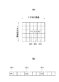
図7(a),(b)は、本発明の表示装置の第二実施形態に係る入力画像の一例を示す図であり、同図(a)は入力画像例を示し、同図(b)はその入力画像の一部を拡大した例を示す。 FIGS. 7A and 7B are diagrams showing an example of an input image according to the second embodiment of the display device of the present invention. FIG. 7A shows an example of the input image, and FIG. Shows an example in which a part of the input image is enlarged.
同図(a)の401,402,403は隣り合った3個の画素を示している。これを4倍に拡大すると、図7(b)に示したようになる。すなわち、各々の画素401,402,403の間に3個の画素を挿入することにより4倍に拡大している。挿入された3個の画素の値は、画像の特性により周辺画素に応じて決定される。
<画像の特徴に最適な拡大補間処理>
図8は、第二実施形態の拡大補間処理を示すフローチャートである。なお、このフローチャートに従ったプログラムを表示装置200内の例えばROM64に格納し、CPU63で実行することにより、以下の制御方法を実現させることが可能となる。
<Enlarged interpolation processing best suited to image features>
FIG. 8 is a flowchart showing the enlargement interpolation process of the second embodiment. The following control method can be realized by storing a program according to this flowchart in, for example, the
まず、画像の特性を検出し拡大補間する方法について説明する。画素401と402の間を補間する場合は、図7(a)に示す様に、まず画素401,402とその周辺画素を含む30個の画素における平均値Mを求める(ステップS601)。ここで、各画素は8ビットの値を持ち、0(黒)から255(白)の256階調の表示を行うものとする。そして、画素401の値をP1、画素402の画素の値をP2とする。
First, a method for detecting the characteristics of an image and performing interpolation for enlargement will be described. When interpolating between the
次に画素401の画素値P1と平均値Mとの差の絶対値が特徴点抽出閾値K1より大きいかを判別し(ステップS602)、大きい場合は、画素401は文字等の特徴点と判断し(ステップS603)、小さい場合は背景画像と判断する(ステップS604)。さらに、画素402の画素値P2と平均値Mとの差の絶対値が特徴点抽出閾値K1より大きいかを判別し(ステップS605)、大きい場合は、画素402は文字等の特徴点と判断し(ステップS606)、小さい場合は背景画像と判断する(ステップS607)。ここで、特徴点抽出閾値K1は、文字等の特徴画像を抽出するため、150以上の値とすることが望ましい。
Next, it is determined whether or not the absolute value of the difference between the pixel value P1 of the
続いて、画素401=P1及び画素402=P2という画像の特徴の組み合わせに応じて、画素間を補間するための重みテーブルを選択する。
Subsequently, a weight table for interpolating between the pixels is selected in accordance with a combination of image features of
ここで、図9および図10の重みテーブルは、縦軸が補間対象画素のP1からの距離aであり、縦軸がP1からの距離aに対応した重み係数h(a)となる。そして、補間対象画素の値Aは、次式より算出される。 Here, in the weight tables of FIGS. 9 and 10, the vertical axis represents the distance a from the interpolation target pixel P1, and the vertical axis represents the weight coefficient h (a) corresponding to the distance a from P1. The value A of the interpolation target pixel is calculated from the following equation.
A=(1/2)・(P1(1−h(a))+P2・h(a)))
P1が背景でありP2が特徴画像である場合は(ステップS608)、図9(a)に示すようなP2に重みのある補正テーブルを使用する(ステップS609)。P1が特徴画像でありP2が背景である場合は(ステップS610)、図9(b)に示すようなP1に重みのある補正テーブルを使用する(ステップS611)。
A = (1/2) · (P1 (1−h (a)) + P2 · h (a)))
When P1 is a background and P2 is a feature image (step S608), a correction table having a weight on P2 as shown in FIG. 9A is used (step S609). When P1 is a feature image and P2 is a background (step S610), a correction table having a weight on P1 as shown in FIG. 9B is used (step S611).
その他の場合は、P1とP2が同じ特徴を持つため、P1とP2がエッジ部であるか否かの判別をP1とP2の差の絶対値がエッジ閾値K2より大きいか否かで、補間テーブルを選択する(ステップS612)。エッジ閾値はエッジを的確に検出するため、100以上の値が望ましい。また、周辺の複数の画素の値に応じてエッジ閾値を変化させる構成とすることも可能であり、この場合は、より小さなエッジも誤判別することなく検出が可能となる。 In other cases, since P1 and P2 have the same characteristics, whether or not P1 and P2 are edge portions is determined based on whether or not the absolute value of the difference between P1 and P2 is larger than the edge threshold value K2. Is selected (step S612). The edge threshold value is preferably 100 or more in order to accurately detect the edge. Further, it is possible to adopt a configuration in which the edge threshold value is changed in accordance with the values of a plurality of peripheral pixels. In this case, it is possible to detect a smaller edge without erroneous determination.
P1とP2の差の絶対値がK2より大きな場合はエッジと判別し(ステップS613)、図10(a)のP1とP2の中間に閾値のある補間テーブルを使用する(ステップS614)。P1とP2の差の絶対値がK2より小さい場合はエッジではないと判別し(ステップS615)、図10(b)のP1とP2の間がリニアな補間テーブルを使用する(ステップS616)。 If the absolute value of the difference between P1 and P2 is larger than K2, it is determined as an edge (step S613), and an interpolation table having a threshold value between P1 and P2 in FIG. 10A is used (step S614). If the absolute value of the difference between P1 and P2 is smaller than K2, it is determined that the edge is not an edge (step S615), and an interpolation table between P1 and P2 in FIG. 10B is used (step S616).
以上の処理により、画像の特徴に最適な拡大補間が可能となる。 With the above processing, enlargement interpolation that is optimal for image features can be performed.
<拡大補間方法に合わせたデジタイザ情報変換方法>
次に、拡大補間方法に合わせて、パソコン300へ送るデジタイザ情報を変換する方法について説明する。
<Digitizer information conversion method according to the enlargement interpolation method>
Next, a method for converting digitizer information to be sent to the
デジタイザ202より位置座標(x,y)を得ると、それを拡大率で割ることにより、拡大前の対応するオリジナル座標を得ることができる。例えば、デジタイザ座標が(362,463)とし、拡大率を4とすると、X座標は362/4=90余り2となり、拡大前のX座標90とX座標91の間を補間していることが判る。Y座標も同様に求めることができる。従って、先に説明した水平方向の拡大補間方法に対応させると、P1=90、P2=91、P1からの距離a=2となる。
When the position coordinates (x, y) are obtained from the
ここで、P1の座標値をもとに、メモリ33に記憶した画像データを読み出し、平均輝度Mを求め、図8に示した拡大補間時のフローに従い、補間用の重み係数テーブルfh(a)を求める。補間テーブルh(a)にa=2を代入することにより、重み係数h(a)を得、重み係数h(a)と閾値K3と比較し、閾値K3より大きければP2をデジタイザ座標とし、閾値K3より小さければP1をデジタイザ座標とする。ここで、閾値K3は、重み係数の中間値0.5を使用したが、表示装置や表示画像の特性に応じて変えてもよい。
Here, based on the coordinate value of P1, the image data stored in the
このように、本実施形態では、拡大補間方法の違いに応じてデジタイザ座標を変えることが可能となる。 Thus, in the present embodiment, the digitizer coordinates can be changed according to the difference in the enlargement interpolation method.
以上、本実施形態によれば、パソコン300より表示装置200に入力された画像を表示装置200で拡大・縮小した後に、表示装置200の表示画面6上の位置を例えばデジタイザ202で指示し、表示装置200またはパソコン300に指示を行う。この場合において、画像の特徴に適した拡大補間方法(解像度変換手法)を用いて表示を行うと共に、拡大補間方法に応じてデジタイザ情報(指示信号)を変換してパソコン300等へ出力する。これにより、拡大補間後の画像に適した指示が可能となり、指示対象の指示に誤操作を招くことや指示画像の表示ずれによる違和感を改善することができる。
As described above, according to the present embodiment, after the image input from the
[変形例]
(1)上記実施形態では、表示装置200にメニュー表示スイッチ(SW)110を設けた場合について説明したが、リモコンにメニュー表示SWを設けて、リモコンより表示装置200にメニュー表示開始及び終了コマンドを送信するようにしても良い。
[Modification]
(1) Although the case where the menu display switch (SW) 110 is provided on the
(2)表示画面6に取り付けられたデジタイザ202を用いた場合について説明したが、表示装置200に接続されたマウスなどの指示装置を用いても同様の効果が達成できる。
(2) Although the case where the
(3)上記実施形態では、背面投射型表示装置の例について示したが、デジタイザを使用可能な表示装置であれば何れのものでも良く、例えば、PDP、LCD、CRT、フロントプロジェクタ等の表示装置でも実施可能である。 (3) In the above embodiment, an example of a rear projection display device has been described. However, any display device that can use a digitizer may be used. For example, a display device such as a PDP, LCD, CRT, or front projector. But it is possible.
(4)リモコンを用いた場合においても、リモコンの指示による指示情報を用いれば、同様の使用方法を実現でき、便利性が向上する。 (4) Even when a remote controller is used, the same usage method can be realized and the convenience can be improved by using the instruction information by the instruction of the remote controller.
(5)メニュー表示画像500上でのクリックによる選択信号をポイントコマンドに変換して送ることも可能である。この場合は、パソコン300によって表示されるカーソルは、メニュー表示画像500の下に隠すことができる。ポイントコマンドなので、パソコン300の誤動作等の影響を与えることはない。
(5) It is also possible to convert a selection signal by clicking on the
(6)上記実施形態では、パンモードやズームモード時に指示信号をパソコン300へ送らない場合について説明したが、クリックによる選択信号やドラッグ信号をポイントコマンドに変換して送ることにより、パソコン300によって発生したカーソルを表示することも可能である。この場合も、ポイント信号に変換しているため、パソコン300等の誤動作を招くことはない。
(6) In the above embodiment, the case where the instruction signal is not sent to the
(7)上記実施形態では、エッジ検出は、隣接する2画素との差を採ると説明したが、隣接する数画素をみて近似曲線とのずれ量等で判断する方法も適用可能である。 (7) In the above-described embodiment, it has been described that edge detection takes the difference between two adjacent pixels, but a method of judging by the amount of deviation from the approximate curve by looking at several adjacent pixels is also applicable.
本発明は、上述した実施形態の装置に限定されず、複数の機器から構成されるシステムに適用しても、1つの機器から成る装置に適用しても良い。前述した実施形態の機能を実現するソフトウェアのプログラムコードを記憶した記憶媒体をシステムあるいは装置に供給し、そのシステムあるいは装置のコンピュータ(またはCPUやMPU)が記憶媒体に格納されたプログラムコードを読み出し実行することによっても、完成されることは言うまでもない。 The present invention is not limited to the apparatus of the above-described embodiment, and may be applied to a system composed of a plurality of devices or an apparatus composed of one device. A storage medium storing software program codes for realizing the functions of the above-described embodiments is supplied to a system or apparatus, and a computer (or CPU or MPU) of the system or apparatus reads and executes the program codes stored in the storage medium. Needless to say, it will be completed by doing.
この場合、記憶媒体から読み出されたプログラムコード自体が前述した実施形態の機能を実現することになり、そのプログラムコードを記憶した記憶媒体は本発明を構成することになる。プログラムコードを供給するための記憶媒体としては、例えば、フロッピー(登録商標)ディスク、ハードディスク、光ディスク、光磁気ディスク、CD−ROM、CD−R、磁気テープ、不揮発性のメモリカード、ROMを用いることができる。また、コンピュータが読み出したプログラムコードを実行することにより、前述した実施形態の機能が実現されるだけではなく、そのプログラムコードの指示に基づき、コンピュータ上で稼動しているOSなどが実際の処理の一部または全部を行い、その処理によって前述した実施形態の機能が実現される場合も含まれることは言うまでもない。 In this case, the program code itself read from the storage medium realizes the functions of the above-described embodiments, and the storage medium storing the program code constitutes the present invention. As a storage medium for supplying the program code, for example, a floppy (registered trademark) disk, hard disk, optical disk, magneto-optical disk, CD-ROM, CD-R, magnetic tape, nonvolatile memory card, ROM is used. Can do. In addition, by executing the program code read by the computer, not only the functions of the above-described embodiments are realized, but also the OS running on the computer based on the instruction of the program code performs the actual processing. Needless to say, a case where the function of the above-described embodiment is realized by performing part or all of the processing is also included.
さらに、記憶媒体から読み出されたプログラムコードが、コンピュータに挿入された機能拡張ボードやコンピュータに接続された機能拡張ユニットに備わるメモリに書き込まれた後、次のプログラムコードの指示に基づき、その拡張機能を拡張ボードや拡張ユニットに備わるCPUなどが処理を行って実際の処理の一部または全部を行い、その処理によって前述した実施形態の機能が実現される場合も含まれることは言うまでもない。 Furthermore, after the program code read from the storage medium is written to the memory provided in the function expansion board inserted in the computer or the function expansion unit connected to the computer, the program code is expanded based on the instruction of the next program code. It goes without saying that the functions of the above-described embodiments may be realized by performing some or all of the actual processing by the CPU or the like provided on the expansion board or the expansion unit.
D1 投射型表示エンジン
3 映像信号処理部
6 スクリーン
63 CPU
64 ROM
65 RAM
101 オーバーレイ(1)用切り替え回路
102 オーバーレイ(2)用切り替え回路
103 オーバーレイ(1)画像メモリ
104 オーバーレイ(2)画像メモリ
112 ズーム拡大率設定部
113 カーソル画像記憶部
114 カーソル表示位置設定部
115 メニュー画像記憶部
116 メニュー表示位置設定部
117 パンモード表示位置演算部
118 デジタイザ検出部
119 表示座標演算部
120 解像度変換回路
200 背面投射型表示装置
202 デジタイザ
203 デジタイザ用ペン
300 パソコン
500 メニュー画像表示
506 カーソル
D1 Projection display engine 3
64 ROM
65 RAM
101 Overlay (1)
Claims (6)
前記画像信号の画像を拡大処理する際に前記画像信号の画像の隣接する第1の画素と第2の画素の間に挿入される第3の画素の画素値を、前記第1の画素の画素値よりも前記第2の画素の画素値に重く重み付けして算出される画素値にするか、前記第2の画素の画素値よりも前記第1の画素の画素値に重く重み付けして算出される画素値にするかを決定する決定手段と、
前記決定手段による決定に基づいて拡大処理された画像を表示する表示手段と、
前記拡大処理された画像を表示する表示手段において指示された前記第3の画素の画素値が、前記第1の画素の画素値よりも前記第2の画素の画素値に重く重み付けして算出される画素値であった場合、前記第2の画素が指示されたことを示す第1の座標情報を前記画像出力機器へ出力し、前記第3の画素の画素値が、前記第2の画素の画素値よりも前記第1の画素の画素値に重く重み付けして算出される画素値であった場合、前記第1の画素が指示されたことを示す第2の座標情報を前記画像出力機器へ出力する出力手段とを
備えたことを特徴とする表示装置。 In a display device that displays an enlarged image of an image signal output from an image output device,
When enlarging the image of the image signal, the pixel value of the third pixel inserted between the adjacent first pixel and second pixel of the image of the image signal is the pixel of the first pixel. The pixel value is calculated by weighting the pixel value of the second pixel more heavily than the value, or is calculated by weighting the pixel value of the first pixel more heavily than the pixel value of the second pixel. Determining means for determining whether or not to obtain a pixel value;
Display means for displaying an enlarged image based on the determination by the determination means;
The pixel value of the third pixel instructed by the display means for displaying the enlarged image is calculated by weighting the pixel value of the second pixel more heavily than the pixel value of the first pixel. The first coordinate information indicating that the second pixel has been designated is output to the image output device, and the pixel value of the third pixel is the second pixel value. When the pixel value is calculated by weighting the pixel value of the first pixel more heavily than the pixel value, the second coordinate information indicating that the first pixel is designated is sent to the image output device. A display device comprising output means for outputting .
前記決定手段は、前記判定手段による前記第1の画素と前記第2の画素に対する判定結果に応じて、前記第3の画素の画素値を前記第1の画素の画素値よりも前記第2の画素の画素値に重く重み付けして算出される画素値にするか、前記第2の画素の画素値よりも前記第1の画素の画素値に重く重み付けして算出される画素値にするかを決定することを特徴とする請求項1に記載の表示装置。 Determination means for determining whether a pixel of an image of the image signal is a feature pixel ;
The determining means sets the pixel value of the third pixel to be greater than the pixel value of the first pixel in accordance with the determination result for the first pixel and the second pixel by the determining means . Whether the pixel value is calculated by heavily weighting the pixel value of the pixel, or the pixel value is calculated by weighting the pixel value of the first pixel more heavily than the pixel value of the second pixel the display device according to claim 1, characterized in that the determining.
前記第2の画素が特徴画素でないと判定された場合、前記第1の画素と第2の画素の中間の画素である第3の画素の画素値を、前記第2の画素の画素値よりも前記第1の画素の画素値に重く重み付けして算出された画素値にすることを決定し、
前記判定手段によって前記第1の画素が特徴画素であると判定され、前記第2の画素が特徴画素でないと判定された場合、前記第3の画素の画素値を、前記第1の画素の画素値よりも前記第2の画素の画素値に重く重み付けして算出された画素値にすることを決定することを特徴とする請求項2に記載の表示装置。 The determining means determines that the first pixel is a feature pixel by the determining means,
When it is determined that the second pixel is not a feature pixel, a pixel value of a third pixel that is an intermediate pixel between the first pixel and the second pixel is set to be greater than a pixel value of the second pixel. Determining a pixel value calculated by weighting the pixel value of the first pixel heavily;
When the determination unit determines that the first pixel is a feature pixel and the second pixel is not a feature pixel, the pixel value of the third pixel is determined as the pixel value of the first pixel. The display device according to claim 2 , wherein the pixel value is calculated by weighting the pixel value of the second pixel more heavily than the value .
前記第1の画素よりも前記第2の画素の近くに位置する画素の画素値を、前記第1の画素の画素値よりも前記第2の画素の画素値に重く重み付けして算出される画素値とし、
前記第2の画素よりも前記第1の画素の近くに位置する画素の画素値を、前記第2の画素の画素値よりも前記第1の画素の画素値に重く重み付けして算出される画素値とすることを決定することを特徴とする請求項2に記載の表示装置。 The determining means determines that the first and second pixels are both characteristic pixels or the first and second pixels are not characteristic pixels when the determining means determines that the first and second pixels are not characteristic pixels. Among a plurality of pixels inserted between a pixel and the second pixel,
A pixel calculated by weighting a pixel value of a pixel located closer to the second pixel than the first pixel more heavily than a pixel value of the second pixel rather than a pixel value of the first pixel Value and
A pixel calculated by weighting a pixel value of a pixel located closer to the first pixel than the second pixel more heavily than the pixel value of the first pixel than the pixel value of the second pixel The display device according to claim 2 , wherein the display device is determined to be a value .
前記画像信号の画像を拡大処理する際に前記画像信号の画像の隣接する第1の画素と第2の画素の間に挿入される第3の画素の画素値を、前記第1の画素の画素値よりも前記第2の画素の画素値に重く重み付けして算出される画素値にするか、前記第2の画素の画素値よりも前記第1の画素の画素値に重く重み付けして算出される画素値にするかを決定する決定工程と、
前記決定工程による決定に基づいて拡大処理された画像を表示手段に表示させる表示工程と、
前記拡大処理された画像を表示する前記表示手段において指示された前記第3の画素の画素値が、前記第1の画素の画素値よりも前記第2の画素の画素値に重く重み付けして算出される画素値であった場合、前記第2の画素が指示されたことを示す第1の座標情報を前記画像出力機器へ出力し、前記第3の画素の画素値が、前記第2の画素の画素値よりも前記第1の画素の画素値に重く重み付けして算出される画素値であった場合、前記第1の画素が指示されたことを示す第2の座標情報を前記画像出力機器へ出力する出力工程とを有することを特徴とする表示装置の制御方法。 In a control method for a display device that displays an enlarged image of an image signal output from an image output device,
When enlarging the image of the image signal, the pixel value of the third pixel inserted between the adjacent first pixel and second pixel of the image of the image signal is the pixel of the first pixel. The pixel value is calculated by weighting the pixel value of the second pixel more heavily than the value, or is calculated by weighting the pixel value of the first pixel more heavily than the pixel value of the second pixel. A determination step for determining whether to obtain a pixel value;
A display step of displaying on the display means an image enlarged based on the determination by the determination step;
The pixel value of the third pixel instructed by the display means for displaying the enlarged image is calculated by weighting the pixel value of the second pixel more heavily than the pixel value of the first pixel. The first coordinate information indicating that the second pixel has been designated is output to the image output device, and the pixel value of the third pixel is the second pixel. If the pixel value is calculated by weighting the pixel value of the first pixel more heavily than the pixel value of the first pixel value, the second coordinate information indicating that the first pixel is designated is indicated by the image output device. An output process for outputting to the display device.
前記画像信号の画像を拡大処理する際に前記画像信号の画像の隣接する第1の画素と第2の画素の間に挿入される第3の画素の画素値を、前記第1の画素の画素値よりも前記第2の画素の画素値に重く重み付けして算出される画素値にするか、前記第2の画素の画素値よりも前記第1の画素の画素値に重く重み付けして算出される画素値にするかを決定する決定手順と、
前記決定手順による決定に基づいて拡大処理された画像を表示手段に表示させる表示手順と、
前記拡大処理された画像を表示する前記表示手段において指示された前記第3の画素の画素値が、前記第1の画素の画素値よりも前記第2の画素の画素値に重く重み付けして算出される画素値であった場合、前記第2の画素が指示されたことを示す第1の座標情報を前記画像出力機器へ出力し、前記第3の画素の画素値が、前記第2の画素の画素値よりも前記第1の画素の画素値に重く重み付けして算出される画素値であった場合、前記第1の画素が指示されたことを示す第2の座標情報を前記画像出力機器へ出力する出力手順と
を実行させることを特徴とする制御プログラム。 A computer that displays an enlarged image of the image signal output from the image output device.
When enlarging the image of the image signal, the pixel value of the third pixel inserted between the adjacent first pixel and second pixel of the image of the image signal is the pixel of the first pixel. The pixel value is calculated by weighting the pixel value of the second pixel more heavily than the value, or is calculated by weighting the pixel value of the first pixel more heavily than the pixel value of the second pixel. A determination procedure for determining whether to set a pixel value to be
A display procedure for causing the display means to display an enlarged image based on the determination by the determination procedure;
The pixel value of the third pixel instructed by the display means for displaying the enlarged image is calculated by weighting the pixel value of the second pixel more heavily than the pixel value of the first pixel. The first coordinate information indicating that the second pixel has been designated is output to the image output device, and the pixel value of the third pixel is the second pixel. If the pixel value is calculated by weighting the pixel value of the first pixel more heavily than the pixel value of the first pixel value, the second coordinate information indicating that the first pixel is designated is indicated by the image output device. Output procedure to output to
A control program characterized by causing
Priority Applications (3)
| Application Number | Priority Date | Filing Date | Title |
|---|---|---|---|
| JP2004083351A JP4564767B2 (en) | 2004-03-22 | 2004-03-22 | Display device, control method therefor, and control program |
| CNB2005100548873A CN100354818C (en) | 2004-03-22 | 2005-03-22 | Display apparatus, control method therefor, and control program |
| US11/086,477 US7535455B2 (en) | 2004-03-22 | 2005-03-22 | Display apparatus, control method therefor, and control program for implementing the control method |
Applications Claiming Priority (1)
| Application Number | Priority Date | Filing Date | Title |
|---|---|---|---|
| JP2004083351A JP4564767B2 (en) | 2004-03-22 | 2004-03-22 | Display device, control method therefor, and control program |
Publications (3)
| Publication Number | Publication Date |
|---|---|
| JP2005275450A JP2005275450A (en) | 2005-10-06 |
| JP2005275450A5 JP2005275450A5 (en) | 2007-04-26 |
| JP4564767B2 true JP4564767B2 (en) | 2010-10-20 |
Family
ID=35046518
Family Applications (1)
| Application Number | Title | Priority Date | Filing Date |
|---|---|---|---|
| JP2004083351A Expired - Fee Related JP4564767B2 (en) | 2004-03-22 | 2004-03-22 | Display device, control method therefor, and control program |
Country Status (3)
| Country | Link |
|---|---|
| US (1) | US7535455B2 (en) |
| JP (1) | JP4564767B2 (en) |
| CN (1) | CN100354818C (en) |
Families Citing this family (14)
| Publication number | Priority date | Publication date | Assignee | Title |
|---|---|---|---|---|
| JP5110862B2 (en) * | 2006-12-01 | 2012-12-26 | キヤノン株式会社 | Liquid crystal display device and control method thereof, computer program, and storage medium |
| JP5136424B2 (en) * | 2007-01-26 | 2013-02-06 | 日本電気株式会社 | Image processing apparatus, method, program, and display apparatus |
| JP4450014B2 (en) * | 2007-05-30 | 2010-04-14 | セイコーエプソン株式会社 | Projector, image display device, and image processing device |
| JP5060873B2 (en) * | 2007-08-24 | 2012-10-31 | 東レ・ダウコーニング株式会社 | Silicone pressure-sensitive adhesive composition and pressure-sensitive adhesive tape or sheet |
| US8089557B2 (en) * | 2007-10-04 | 2012-01-03 | Hitachi, Ltd. | Video signal processing apparatus, video signal processing method and video display apparatus |
| JP5173756B2 (en) * | 2008-11-12 | 2013-04-03 | キヤノン株式会社 | Image display device |
| JPWO2010073363A1 (en) * | 2008-12-26 | 2012-05-31 | 富士通株式会社 | Resolution changing apparatus, resolution changing method, and resolution changing program |
| JP2010160576A (en) * | 2009-01-06 | 2010-07-22 | Toshiba Corp | Image reproduction apparatus and image processing apparatus |
| CN102576280A (en) * | 2009-07-02 | 2012-07-11 | 自由科学有限公司 | Magnification interface with independent pointer sizing |
| DE102010014796A1 (en) * | 2010-02-03 | 2011-08-04 | Emerging Display Technologies Corp. | Screen unit with a touch screen |
| JP5454722B2 (en) * | 2011-11-30 | 2014-03-26 | 株式会社リコー | Projector, display device, method and program |
| JP6014137B2 (en) * | 2012-06-29 | 2016-10-25 | 日立マクセル株式会社 | Display system and display terminal |
| WO2022070462A1 (en) * | 2020-09-29 | 2022-04-07 | 富士フイルム株式会社 | Control device, control method, control program, and projection system |
| CN113823211B (en) * | 2021-09-28 | 2022-08-23 | 惠科股份有限公司 | Driving method, driving device and display device |
Citations (1)
| Publication number | Priority date | Publication date | Assignee | Title |
|---|---|---|---|---|
| JP2001142645A (en) * | 1999-11-11 | 2001-05-25 | Fujitsu General Ltd | Image display device having touch panel |
Family Cites Families (13)
| Publication number | Priority date | Publication date | Assignee | Title |
|---|---|---|---|---|
| US6141000A (en) * | 1991-10-21 | 2000-10-31 | Smart Technologies Inc. | Projection display system with touch sensing on screen, computer assisted alignment correction and network conferencing |
| JPH05204374A (en) | 1992-01-29 | 1993-08-13 | Nec Corp | Picture display control system |
| JP2830580B2 (en) | 1992-02-21 | 1998-12-02 | 日本電気株式会社 | Image display device |
| JPH06139234A (en) | 1992-10-23 | 1994-05-20 | Matsushita Electric Ind Co Ltd | Display device |
| JP2648558B2 (en) * | 1993-06-29 | 1997-09-03 | インターナショナル・ビジネス・マシーンズ・コーポレイション | Information selection device and information selection method |
| JPH1069345A (en) * | 1996-08-28 | 1998-03-10 | Sharp Corp | Image processor |
| US5881169A (en) * | 1996-09-13 | 1999-03-09 | Ericsson Inc. | Apparatus and method for presenting and gathering text entries in a pen-based input device |
| JPH1185132A (en) | 1997-09-08 | 1999-03-30 | Sanyo Electric Co Ltd | Portable information terminal device |
| JPH11175245A (en) | 1997-12-17 | 1999-07-02 | Canon Inc | Coordinate output device |
| JP3475235B2 (en) * | 1999-03-08 | 2003-12-08 | 東京農工大学長 | Display device control method |
| US6683604B1 (en) * | 2000-04-04 | 2004-01-27 | Pixelworks, Inc. | Failsafe display of frame locked graphics |
| US6727896B2 (en) * | 2001-08-01 | 2004-04-27 | Microsoft Corporation | Correction of alignment and linearity errors in a stylus input system |
| JP4215549B2 (en) * | 2003-04-02 | 2009-01-28 | 富士通株式会社 | Information processing device that operates in touch panel mode and pointing device mode |
-
2004
- 2004-03-22 JP JP2004083351A patent/JP4564767B2/en not_active Expired - Fee Related
-
2005
- 2005-03-22 CN CNB2005100548873A patent/CN100354818C/en not_active Expired - Fee Related
- 2005-03-22 US US11/086,477 patent/US7535455B2/en not_active Expired - Fee Related
Patent Citations (1)
| Publication number | Priority date | Publication date | Assignee | Title |
|---|---|---|---|---|
| JP2001142645A (en) * | 1999-11-11 | 2001-05-25 | Fujitsu General Ltd | Image display device having touch panel |
Also Published As
| Publication number | Publication date |
|---|---|
| US7535455B2 (en) | 2009-05-19 |
| CN100354818C (en) | 2007-12-12 |
| CN1673952A (en) | 2005-09-28 |
| US20050219269A1 (en) | 2005-10-06 |
| JP2005275450A (en) | 2005-10-06 |
Similar Documents
| Publication | Publication Date | Title |
|---|---|---|
| US7535455B2 (en) | Display apparatus, control method therefor, and control program for implementing the control method | |
| US11625876B2 (en) | Presentation system and display device for use in the presentation system | |
| TW546626B (en) | Method and apparatus for adjusting contrast and sharpness for regions in a display device | |
| JP3953500B1 (en) | Image projection method and projector | |
| EP1998572A2 (en) | Projector, image display system and image processing system | |
| JP5082722B2 (en) | Image display device and image display system | |
| US20050243073A1 (en) | Presentation device and display method | |
| JP2005215542A (en) | Video projector device and method for adjusting position of projection video thereof | |
| JP2005323389A (en) | Projection-type image display device | |
| JP2008102332A (en) | Projector | |
| JP2008122800A (en) | Image display device | |
| JP2018026742A (en) | Display device and method for controlling the same | |
| JP5245805B2 (en) | Projector, control method therefor, and control program therefor | |
| JP4849302B2 (en) | Display control apparatus, display control method, and program | |
| JP2007249482A (en) | Projector and pointer program | |
| JP2011029728A (en) | Image display device | |
| JP4530058B2 (en) | Projector, highlighting method | |
| JP2006202107A (en) | Image display device and image display method | |
| JP2003046908A (en) | Projection image display system | |
| JP2001350585A (en) | Image display device with coordinate input function | |
| JP2005045769A (en) | Image display device and image display method | |
| JP7238878B2 (en) | DISPLAY DEVICE AND CONTROL METHOD OF DISPLAY DEVICE | |
| JP4541863B2 (en) | Display device, display system, display control method, and program | |
| JP4533078B2 (en) | Display control apparatus and display control method | |
| JP4947158B2 (en) | Image display device and highlighting method |
Legal Events
| Date | Code | Title | Description |
|---|---|---|---|
| RD03 | Notification of appointment of power of attorney |
Free format text: JAPANESE INTERMEDIATE CODE: A7423 Effective date: 20060418 |
|
| A521 | Request for written amendment filed |
Free format text: JAPANESE INTERMEDIATE CODE: A523 Effective date: 20070312 |
|
| A621 | Written request for application examination |
Free format text: JAPANESE INTERMEDIATE CODE: A621 Effective date: 20070312 |
|
| RD05 | Notification of revocation of power of attorney |
Free format text: JAPANESE INTERMEDIATE CODE: A7425 Effective date: 20070626 |
|
| A977 | Report on retrieval |
Free format text: JAPANESE INTERMEDIATE CODE: A971007 Effective date: 20090427 |
|
| A131 | Notification of reasons for refusal |
Free format text: JAPANESE INTERMEDIATE CODE: A131 Effective date: 20090519 |
|
| A521 | Request for written amendment filed |
Free format text: JAPANESE INTERMEDIATE CODE: A523 Effective date: 20090624 |
|
| TRDD | Decision of grant or rejection written | ||
| A01 | Written decision to grant a patent or to grant a registration (utility model) |
Free format text: JAPANESE INTERMEDIATE CODE: A01 Effective date: 20100727 |
|
| A01 | Written decision to grant a patent or to grant a registration (utility model) |
Free format text: JAPANESE INTERMEDIATE CODE: A01 |
|
| A61 | First payment of annual fees (during grant procedure) |
Free format text: JAPANESE INTERMEDIATE CODE: A61 Effective date: 20100802 |
|
| FPAY | Renewal fee payment (event date is renewal date of database) |
Free format text: PAYMENT UNTIL: 20130806 Year of fee payment: 3 |
|
| R150 | Certificate of patent or registration of utility model |
Ref document number: 4564767 Country of ref document: JP Free format text: JAPANESE INTERMEDIATE CODE: R150 Free format text: JAPANESE INTERMEDIATE CODE: R150 |
|
| LAPS | Cancellation because of no payment of annual fees |