JP4561663B2 - Hybrid vehicle mode switching control device - Google Patents
Hybrid vehicle mode switching control device Download PDFInfo
- Publication number
- JP4561663B2 JP4561663B2 JP2006080600A JP2006080600A JP4561663B2 JP 4561663 B2 JP4561663 B2 JP 4561663B2 JP 2006080600 A JP2006080600 A JP 2006080600A JP 2006080600 A JP2006080600 A JP 2006080600A JP 4561663 B2 JP4561663 B2 JP 4561663B2
- Authority
- JP
- Japan
- Prior art keywords
- clutch
- engine
- generator
- motor
- mode
- Prior art date
- Legal status (The legal status is an assumption and is not a legal conclusion. Google has not performed a legal analysis and makes no representation as to the accuracy of the status listed.)
- Expired - Fee Related
Links
Images
Classifications
-
- B—PERFORMING OPERATIONS; TRANSPORTING
- B60—VEHICLES IN GENERAL
- B60W—CONJOINT CONTROL OF VEHICLE SUB-UNITS OF DIFFERENT TYPE OR DIFFERENT FUNCTION; CONTROL SYSTEMS SPECIALLY ADAPTED FOR HYBRID VEHICLES; ROAD VEHICLE DRIVE CONTROL SYSTEMS FOR PURPOSES NOT RELATED TO THE CONTROL OF A PARTICULAR SUB-UNIT
- B60W20/00—Control systems specially adapted for hybrid vehicles
- B60W20/10—Controlling the power contribution of each of the prime movers to meet required power demand
- B60W20/15—Control strategies specially adapted for achieving a particular effect
-
- B—PERFORMING OPERATIONS; TRANSPORTING
- B60—VEHICLES IN GENERAL
- B60K—ARRANGEMENT OR MOUNTING OF PROPULSION UNITS OR OF TRANSMISSIONS IN VEHICLES; ARRANGEMENT OR MOUNTING OF PLURAL DIVERSE PRIME-MOVERS IN VEHICLES; AUXILIARY DRIVES FOR VEHICLES; INSTRUMENTATION OR DASHBOARDS FOR VEHICLES; ARRANGEMENTS IN CONNECTION WITH COOLING, AIR INTAKE, GAS EXHAUST OR FUEL SUPPLY OF PROPULSION UNITS IN VEHICLES
- B60K6/00—Arrangement or mounting of plural diverse prime-movers for mutual or common propulsion, e.g. hybrid propulsion systems comprising electric motors and internal combustion engines
- B60K6/20—Arrangement or mounting of plural diverse prime-movers for mutual or common propulsion, e.g. hybrid propulsion systems comprising electric motors and internal combustion engines the prime-movers consisting of electric motors and internal combustion engines, e.g. HEVs
- B60K6/22—Arrangement or mounting of plural diverse prime-movers for mutual or common propulsion, e.g. hybrid propulsion systems comprising electric motors and internal combustion engines the prime-movers consisting of electric motors and internal combustion engines, e.g. HEVs characterised by apparatus, components or means specially adapted for HEVs
- B60K6/36—Arrangement or mounting of plural diverse prime-movers for mutual or common propulsion, e.g. hybrid propulsion systems comprising electric motors and internal combustion engines the prime-movers consisting of electric motors and internal combustion engines, e.g. HEVs characterised by apparatus, components or means specially adapted for HEVs characterised by the transmission gearings
- B60K6/365—Arrangement or mounting of plural diverse prime-movers for mutual or common propulsion, e.g. hybrid propulsion systems comprising electric motors and internal combustion engines the prime-movers consisting of electric motors and internal combustion engines, e.g. HEVs characterised by apparatus, components or means specially adapted for HEVs characterised by the transmission gearings with the gears having orbital motion
-
- B—PERFORMING OPERATIONS; TRANSPORTING
- B60—VEHICLES IN GENERAL
- B60K—ARRANGEMENT OR MOUNTING OF PROPULSION UNITS OR OF TRANSMISSIONS IN VEHICLES; ARRANGEMENT OR MOUNTING OF PLURAL DIVERSE PRIME-MOVERS IN VEHICLES; AUXILIARY DRIVES FOR VEHICLES; INSTRUMENTATION OR DASHBOARDS FOR VEHICLES; ARRANGEMENTS IN CONNECTION WITH COOLING, AIR INTAKE, GAS EXHAUST OR FUEL SUPPLY OF PROPULSION UNITS IN VEHICLES
- B60K6/00—Arrangement or mounting of plural diverse prime-movers for mutual or common propulsion, e.g. hybrid propulsion systems comprising electric motors and internal combustion engines
- B60K6/20—Arrangement or mounting of plural diverse prime-movers for mutual or common propulsion, e.g. hybrid propulsion systems comprising electric motors and internal combustion engines the prime-movers consisting of electric motors and internal combustion engines, e.g. HEVs
- B60K6/22—Arrangement or mounting of plural diverse prime-movers for mutual or common propulsion, e.g. hybrid propulsion systems comprising electric motors and internal combustion engines the prime-movers consisting of electric motors and internal combustion engines, e.g. HEVs characterised by apparatus, components or means specially adapted for HEVs
- B60K6/38—Arrangement or mounting of plural diverse prime-movers for mutual or common propulsion, e.g. hybrid propulsion systems comprising electric motors and internal combustion engines the prime-movers consisting of electric motors and internal combustion engines, e.g. HEVs characterised by apparatus, components or means specially adapted for HEVs characterised by the driveline clutches
- B60K6/387—Actuated clutches, i.e. clutches engaged or disengaged by electric, hydraulic or mechanical actuating means
-
- B—PERFORMING OPERATIONS; TRANSPORTING
- B60—VEHICLES IN GENERAL
- B60K—ARRANGEMENT OR MOUNTING OF PROPULSION UNITS OR OF TRANSMISSIONS IN VEHICLES; ARRANGEMENT OR MOUNTING OF PLURAL DIVERSE PRIME-MOVERS IN VEHICLES; AUXILIARY DRIVES FOR VEHICLES; INSTRUMENTATION OR DASHBOARDS FOR VEHICLES; ARRANGEMENTS IN CONNECTION WITH COOLING, AIR INTAKE, GAS EXHAUST OR FUEL SUPPLY OF PROPULSION UNITS IN VEHICLES
- B60K6/00—Arrangement or mounting of plural diverse prime-movers for mutual or common propulsion, e.g. hybrid propulsion systems comprising electric motors and internal combustion engines
- B60K6/20—Arrangement or mounting of plural diverse prime-movers for mutual or common propulsion, e.g. hybrid propulsion systems comprising electric motors and internal combustion engines the prime-movers consisting of electric motors and internal combustion engines, e.g. HEVs
- B60K6/42—Arrangement or mounting of plural diverse prime-movers for mutual or common propulsion, e.g. hybrid propulsion systems comprising electric motors and internal combustion engines the prime-movers consisting of electric motors and internal combustion engines, e.g. HEVs characterised by the architecture of the hybrid electric vehicle
- B60K6/46—Series type
-
- B—PERFORMING OPERATIONS; TRANSPORTING
- B60—VEHICLES IN GENERAL
- B60K—ARRANGEMENT OR MOUNTING OF PROPULSION UNITS OR OF TRANSMISSIONS IN VEHICLES; ARRANGEMENT OR MOUNTING OF PLURAL DIVERSE PRIME-MOVERS IN VEHICLES; AUXILIARY DRIVES FOR VEHICLES; INSTRUMENTATION OR DASHBOARDS FOR VEHICLES; ARRANGEMENTS IN CONNECTION WITH COOLING, AIR INTAKE, GAS EXHAUST OR FUEL SUPPLY OF PROPULSION UNITS IN VEHICLES
- B60K6/00—Arrangement or mounting of plural diverse prime-movers for mutual or common propulsion, e.g. hybrid propulsion systems comprising electric motors and internal combustion engines
- B60K6/20—Arrangement or mounting of plural diverse prime-movers for mutual or common propulsion, e.g. hybrid propulsion systems comprising electric motors and internal combustion engines the prime-movers consisting of electric motors and internal combustion engines, e.g. HEVs
- B60K6/42—Arrangement or mounting of plural diverse prime-movers for mutual or common propulsion, e.g. hybrid propulsion systems comprising electric motors and internal combustion engines the prime-movers consisting of electric motors and internal combustion engines, e.g. HEVs characterised by the architecture of the hybrid electric vehicle
- B60K6/48—Parallel type
-
- B—PERFORMING OPERATIONS; TRANSPORTING
- B60—VEHICLES IN GENERAL
- B60K—ARRANGEMENT OR MOUNTING OF PROPULSION UNITS OR OF TRANSMISSIONS IN VEHICLES; ARRANGEMENT OR MOUNTING OF PLURAL DIVERSE PRIME-MOVERS IN VEHICLES; AUXILIARY DRIVES FOR VEHICLES; INSTRUMENTATION OR DASHBOARDS FOR VEHICLES; ARRANGEMENTS IN CONNECTION WITH COOLING, AIR INTAKE, GAS EXHAUST OR FUEL SUPPLY OF PROPULSION UNITS IN VEHICLES
- B60K6/00—Arrangement or mounting of plural diverse prime-movers for mutual or common propulsion, e.g. hybrid propulsion systems comprising electric motors and internal combustion engines
- B60K6/20—Arrangement or mounting of plural diverse prime-movers for mutual or common propulsion, e.g. hybrid propulsion systems comprising electric motors and internal combustion engines the prime-movers consisting of electric motors and internal combustion engines, e.g. HEVs
- B60K6/50—Architecture of the driveline characterised by arrangement or kind of transmission units
- B60K6/54—Transmission for changing ratio
- B60K6/547—Transmission for changing ratio the transmission being a stepped gearing
-
- B—PERFORMING OPERATIONS; TRANSPORTING
- B60—VEHICLES IN GENERAL
- B60W—CONJOINT CONTROL OF VEHICLE SUB-UNITS OF DIFFERENT TYPE OR DIFFERENT FUNCTION; CONTROL SYSTEMS SPECIALLY ADAPTED FOR HYBRID VEHICLES; ROAD VEHICLE DRIVE CONTROL SYSTEMS FOR PURPOSES NOT RELATED TO THE CONTROL OF A PARTICULAR SUB-UNIT
- B60W10/00—Conjoint control of vehicle sub-units of different type or different function
- B60W10/02—Conjoint control of vehicle sub-units of different type or different function including control of driveline clutches
-
- B—PERFORMING OPERATIONS; TRANSPORTING
- B60—VEHICLES IN GENERAL
- B60W—CONJOINT CONTROL OF VEHICLE SUB-UNITS OF DIFFERENT TYPE OR DIFFERENT FUNCTION; CONTROL SYSTEMS SPECIALLY ADAPTED FOR HYBRID VEHICLES; ROAD VEHICLE DRIVE CONTROL SYSTEMS FOR PURPOSES NOT RELATED TO THE CONTROL OF A PARTICULAR SUB-UNIT
- B60W10/00—Conjoint control of vehicle sub-units of different type or different function
- B60W10/04—Conjoint control of vehicle sub-units of different type or different function including control of propulsion units
- B60W10/06—Conjoint control of vehicle sub-units of different type or different function including control of propulsion units including control of combustion engines
-
- B—PERFORMING OPERATIONS; TRANSPORTING
- B60—VEHICLES IN GENERAL
- B60W—CONJOINT CONTROL OF VEHICLE SUB-UNITS OF DIFFERENT TYPE OR DIFFERENT FUNCTION; CONTROL SYSTEMS SPECIALLY ADAPTED FOR HYBRID VEHICLES; ROAD VEHICLE DRIVE CONTROL SYSTEMS FOR PURPOSES NOT RELATED TO THE CONTROL OF A PARTICULAR SUB-UNIT
- B60W10/00—Conjoint control of vehicle sub-units of different type or different function
- B60W10/04—Conjoint control of vehicle sub-units of different type or different function including control of propulsion units
- B60W10/08—Conjoint control of vehicle sub-units of different type or different function including control of propulsion units including control of electric propulsion units, e.g. motors or generators
-
- B—PERFORMING OPERATIONS; TRANSPORTING
- B60—VEHICLES IN GENERAL
- B60W—CONJOINT CONTROL OF VEHICLE SUB-UNITS OF DIFFERENT TYPE OR DIFFERENT FUNCTION; CONTROL SYSTEMS SPECIALLY ADAPTED FOR HYBRID VEHICLES; ROAD VEHICLE DRIVE CONTROL SYSTEMS FOR PURPOSES NOT RELATED TO THE CONTROL OF A PARTICULAR SUB-UNIT
- B60W10/00—Conjoint control of vehicle sub-units of different type or different function
- B60W10/10—Conjoint control of vehicle sub-units of different type or different function including control of change-speed gearings
- B60W10/11—Stepped gearings
- B60W10/115—Stepped gearings with planetary gears
-
- B—PERFORMING OPERATIONS; TRANSPORTING
- B60—VEHICLES IN GENERAL
- B60W—CONJOINT CONTROL OF VEHICLE SUB-UNITS OF DIFFERENT TYPE OR DIFFERENT FUNCTION; CONTROL SYSTEMS SPECIALLY ADAPTED FOR HYBRID VEHICLES; ROAD VEHICLE DRIVE CONTROL SYSTEMS FOR PURPOSES NOT RELATED TO THE CONTROL OF A PARTICULAR SUB-UNIT
- B60W20/00—Control systems specially adapted for hybrid vehicles
-
- B—PERFORMING OPERATIONS; TRANSPORTING
- B60—VEHICLES IN GENERAL
- B60W—CONJOINT CONTROL OF VEHICLE SUB-UNITS OF DIFFERENT TYPE OR DIFFERENT FUNCTION; CONTROL SYSTEMS SPECIALLY ADAPTED FOR HYBRID VEHICLES; ROAD VEHICLE DRIVE CONTROL SYSTEMS FOR PURPOSES NOT RELATED TO THE CONTROL OF A PARTICULAR SUB-UNIT
- B60W30/00—Purposes of road vehicle drive control systems not related to the control of a particular sub-unit, e.g. of systems using conjoint control of vehicle sub-units
- B60W30/18—Propelling the vehicle
- B60W30/20—Reducing vibrations in the driveline
-
- B—PERFORMING OPERATIONS; TRANSPORTING
- B60—VEHICLES IN GENERAL
- B60L—PROPULSION OF ELECTRICALLY-PROPELLED VEHICLES; SUPPLYING ELECTRIC POWER FOR AUXILIARY EQUIPMENT OF ELECTRICALLY-PROPELLED VEHICLES; ELECTRODYNAMIC BRAKE SYSTEMS FOR VEHICLES IN GENERAL; MAGNETIC SUSPENSION OR LEVITATION FOR VEHICLES; MONITORING OPERATING VARIABLES OF ELECTRICALLY-PROPELLED VEHICLES; ELECTRIC SAFETY DEVICES FOR ELECTRICALLY-PROPELLED VEHICLES
- B60L2240/00—Control parameters of input or output; Target parameters
- B60L2240/40—Drive Train control parameters
- B60L2240/42—Drive Train control parameters related to electric machines
- B60L2240/421—Speed
-
- B—PERFORMING OPERATIONS; TRANSPORTING
- B60—VEHICLES IN GENERAL
- B60L—PROPULSION OF ELECTRICALLY-PROPELLED VEHICLES; SUPPLYING ELECTRIC POWER FOR AUXILIARY EQUIPMENT OF ELECTRICALLY-PROPELLED VEHICLES; ELECTRODYNAMIC BRAKE SYSTEMS FOR VEHICLES IN GENERAL; MAGNETIC SUSPENSION OR LEVITATION FOR VEHICLES; MONITORING OPERATING VARIABLES OF ELECTRICALLY-PROPELLED VEHICLES; ELECTRIC SAFETY DEVICES FOR ELECTRICALLY-PROPELLED VEHICLES
- B60L2240/00—Control parameters of input or output; Target parameters
- B60L2240/40—Drive Train control parameters
- B60L2240/42—Drive Train control parameters related to electric machines
- B60L2240/423—Torque
-
- B—PERFORMING OPERATIONS; TRANSPORTING
- B60—VEHICLES IN GENERAL
- B60L—PROPULSION OF ELECTRICALLY-PROPELLED VEHICLES; SUPPLYING ELECTRIC POWER FOR AUXILIARY EQUIPMENT OF ELECTRICALLY-PROPELLED VEHICLES; ELECTRODYNAMIC BRAKE SYSTEMS FOR VEHICLES IN GENERAL; MAGNETIC SUSPENSION OR LEVITATION FOR VEHICLES; MONITORING OPERATING VARIABLES OF ELECTRICALLY-PROPELLED VEHICLES; ELECTRIC SAFETY DEVICES FOR ELECTRICALLY-PROPELLED VEHICLES
- B60L2240/00—Control parameters of input or output; Target parameters
- B60L2240/40—Drive Train control parameters
- B60L2240/44—Drive Train control parameters related to combustion engines
- B60L2240/441—Speed
-
- B—PERFORMING OPERATIONS; TRANSPORTING
- B60—VEHICLES IN GENERAL
- B60L—PROPULSION OF ELECTRICALLY-PROPELLED VEHICLES; SUPPLYING ELECTRIC POWER FOR AUXILIARY EQUIPMENT OF ELECTRICALLY-PROPELLED VEHICLES; ELECTRODYNAMIC BRAKE SYSTEMS FOR VEHICLES IN GENERAL; MAGNETIC SUSPENSION OR LEVITATION FOR VEHICLES; MONITORING OPERATING VARIABLES OF ELECTRICALLY-PROPELLED VEHICLES; ELECTRIC SAFETY DEVICES FOR ELECTRICALLY-PROPELLED VEHICLES
- B60L2240/00—Control parameters of input or output; Target parameters
- B60L2240/40—Drive Train control parameters
- B60L2240/48—Drive Train control parameters related to transmissions
- B60L2240/486—Operating parameters
-
- B—PERFORMING OPERATIONS; TRANSPORTING
- B60—VEHICLES IN GENERAL
- B60W—CONJOINT CONTROL OF VEHICLE SUB-UNITS OF DIFFERENT TYPE OR DIFFERENT FUNCTION; CONTROL SYSTEMS SPECIALLY ADAPTED FOR HYBRID VEHICLES; ROAD VEHICLE DRIVE CONTROL SYSTEMS FOR PURPOSES NOT RELATED TO THE CONTROL OF A PARTICULAR SUB-UNIT
- B60W2510/00—Input parameters relating to a particular sub-units
- B60W2510/06—Combustion engines, Gas turbines
- B60W2510/0638—Engine speed
-
- B—PERFORMING OPERATIONS; TRANSPORTING
- B60—VEHICLES IN GENERAL
- B60W—CONJOINT CONTROL OF VEHICLE SUB-UNITS OF DIFFERENT TYPE OR DIFFERENT FUNCTION; CONTROL SYSTEMS SPECIALLY ADAPTED FOR HYBRID VEHICLES; ROAD VEHICLE DRIVE CONTROL SYSTEMS FOR PURPOSES NOT RELATED TO THE CONTROL OF A PARTICULAR SUB-UNIT
- B60W2510/00—Input parameters relating to a particular sub-units
- B60W2510/08—Electric propulsion units
- B60W2510/081—Speed
-
- B—PERFORMING OPERATIONS; TRANSPORTING
- B60—VEHICLES IN GENERAL
- B60W—CONJOINT CONTROL OF VEHICLE SUB-UNITS OF DIFFERENT TYPE OR DIFFERENT FUNCTION; CONTROL SYSTEMS SPECIALLY ADAPTED FOR HYBRID VEHICLES; ROAD VEHICLE DRIVE CONTROL SYSTEMS FOR PURPOSES NOT RELATED TO THE CONTROL OF A PARTICULAR SUB-UNIT
- B60W2510/00—Input parameters relating to a particular sub-units
- B60W2510/10—Change speed gearings
- B60W2510/1015—Input shaft speed, e.g. turbine speed
-
- B—PERFORMING OPERATIONS; TRANSPORTING
- B60—VEHICLES IN GENERAL
- B60W—CONJOINT CONTROL OF VEHICLE SUB-UNITS OF DIFFERENT TYPE OR DIFFERENT FUNCTION; CONTROL SYSTEMS SPECIALLY ADAPTED FOR HYBRID VEHICLES; ROAD VEHICLE DRIVE CONTROL SYSTEMS FOR PURPOSES NOT RELATED TO THE CONTROL OF A PARTICULAR SUB-UNIT
- B60W2510/00—Input parameters relating to a particular sub-units
- B60W2510/10—Change speed gearings
- B60W2510/104—Output speed
-
- B—PERFORMING OPERATIONS; TRANSPORTING
- B60—VEHICLES IN GENERAL
- B60W—CONJOINT CONTROL OF VEHICLE SUB-UNITS OF DIFFERENT TYPE OR DIFFERENT FUNCTION; CONTROL SYSTEMS SPECIALLY ADAPTED FOR HYBRID VEHICLES; ROAD VEHICLE DRIVE CONTROL SYSTEMS FOR PURPOSES NOT RELATED TO THE CONTROL OF A PARTICULAR SUB-UNIT
- B60W2710/00—Output or target parameters relating to a particular sub-units
- B60W2710/02—Clutches
- B60W2710/025—Clutch slip, i.e. difference between input and output speeds
-
- B—PERFORMING OPERATIONS; TRANSPORTING
- B60—VEHICLES IN GENERAL
- B60W—CONJOINT CONTROL OF VEHICLE SUB-UNITS OF DIFFERENT TYPE OR DIFFERENT FUNCTION; CONTROL SYSTEMS SPECIALLY ADAPTED FOR HYBRID VEHICLES; ROAD VEHICLE DRIVE CONTROL SYSTEMS FOR PURPOSES NOT RELATED TO THE CONTROL OF A PARTICULAR SUB-UNIT
- B60W2710/00—Output or target parameters relating to a particular sub-units
- B60W2710/06—Combustion engines, Gas turbines
- B60W2710/0666—Engine torque
-
- B—PERFORMING OPERATIONS; TRANSPORTING
- B60—VEHICLES IN GENERAL
- B60W—CONJOINT CONTROL OF VEHICLE SUB-UNITS OF DIFFERENT TYPE OR DIFFERENT FUNCTION; CONTROL SYSTEMS SPECIALLY ADAPTED FOR HYBRID VEHICLES; ROAD VEHICLE DRIVE CONTROL SYSTEMS FOR PURPOSES NOT RELATED TO THE CONTROL OF A PARTICULAR SUB-UNIT
- B60W2710/00—Output or target parameters relating to a particular sub-units
- B60W2710/08—Electric propulsion units
- B60W2710/083—Torque
-
- Y—GENERAL TAGGING OF NEW TECHNOLOGICAL DEVELOPMENTS; GENERAL TAGGING OF CROSS-SECTIONAL TECHNOLOGIES SPANNING OVER SEVERAL SECTIONS OF THE IPC; TECHNICAL SUBJECTS COVERED BY FORMER USPC CROSS-REFERENCE ART COLLECTIONS [XRACs] AND DIGESTS
- Y02—TECHNOLOGIES OR APPLICATIONS FOR MITIGATION OR ADAPTATION AGAINST CLIMATE CHANGE
- Y02T—CLIMATE CHANGE MITIGATION TECHNOLOGIES RELATED TO TRANSPORTATION
- Y02T10/00—Road transport of goods or passengers
- Y02T10/10—Internal combustion engine [ICE] based vehicles
- Y02T10/40—Engine management systems
-
- Y—GENERAL TAGGING OF NEW TECHNOLOGICAL DEVELOPMENTS; GENERAL TAGGING OF CROSS-SECTIONAL TECHNOLOGIES SPANNING OVER SEVERAL SECTIONS OF THE IPC; TECHNICAL SUBJECTS COVERED BY FORMER USPC CROSS-REFERENCE ART COLLECTIONS [XRACs] AND DIGESTS
- Y02—TECHNOLOGIES OR APPLICATIONS FOR MITIGATION OR ADAPTATION AGAINST CLIMATE CHANGE
- Y02T—CLIMATE CHANGE MITIGATION TECHNOLOGIES RELATED TO TRANSPORTATION
- Y02T10/00—Road transport of goods or passengers
- Y02T10/60—Other road transportation technologies with climate change mitigation effect
- Y02T10/62—Hybrid vehicles
-
- Y—GENERAL TAGGING OF NEW TECHNOLOGICAL DEVELOPMENTS; GENERAL TAGGING OF CROSS-SECTIONAL TECHNOLOGIES SPANNING OVER SEVERAL SECTIONS OF THE IPC; TECHNICAL SUBJECTS COVERED BY FORMER USPC CROSS-REFERENCE ART COLLECTIONS [XRACs] AND DIGESTS
- Y02—TECHNOLOGIES OR APPLICATIONS FOR MITIGATION OR ADAPTATION AGAINST CLIMATE CHANGE
- Y02T—CLIMATE CHANGE MITIGATION TECHNOLOGIES RELATED TO TRANSPORTATION
- Y02T10/00—Road transport of goods or passengers
- Y02T10/60—Other road transportation technologies with climate change mitigation effect
- Y02T10/64—Electric machine technologies in electromobility
Landscapes
- Engineering & Computer Science (AREA)
- Chemical & Material Sciences (AREA)
- Combustion & Propulsion (AREA)
- Transportation (AREA)
- Mechanical Engineering (AREA)
- Automation & Control Theory (AREA)
- Hybrid Electric Vehicles (AREA)
- Electric Propulsion And Braking For Vehicles (AREA)
- Control Of Driving Devices And Active Controlling Of Vehicle (AREA)
- Hydraulic Clutches, Magnetic Clutches, Fluid Clutches, And Fluid Joints (AREA)
- Control Of Transmission Device (AREA)
Description
本発明は、エンジン以外にモータ/ジェネレータからの動力によっても走行することができ、モータ/ジェネレータからの動力のみにより走行する電気走行(EV)モードと、エンジンおよびモータ/ジェネレータの双方からの動力により走行可能なハイブリッド走行(HEV)モードとを有するハイブリッド車両に関し、
特に、後者のHEVモードでの走行中にエンジン出力が不要になって前者のEVモードへ切り換えるに際して要求されるエンジンの停止をショックなく滑らかに行わせるためのモード切り替え制御装置に関するものである。
The present invention can be driven not only by the engine but also by power from the motor / generator, and by electric power (EV) mode in which the vehicle travels only by power from the motor / generator, and by power from both the engine and the motor / generator. Regarding a hybrid vehicle having a hybrid running (HEV) mode capable of running,
In particular, the present invention relates to a mode switching control device for smoothly stopping the engine required when switching to the former EV mode because no engine output is required during traveling in the latter HEV mode.
上記のようなハイブリッド車両に用いるハイブリッド駆動装置としては従来、様々な型式のものが提案されているが、そのうちの1つとして、特許文献1に記載のごときものが知られている。
このハイブリッド駆動装置は、エンジン回転を変速機に向かわせる軸に結合して、これらエンジンおよび変速機間にモータ/ジェネレータを具え、エンジンおよびモータ/ジェネレータ間を切り離し可能に結合する第1クラッチを有すると共に、モータ/ジェネレータおよび変速機出力軸間を切り離し可能に結合する第2クラッチをトルクコンバータの代わりに有した構成になるものである。
Conventionally, various types of hybrid drive apparatuses used in the hybrid vehicle as described above have been proposed. As one of them, the one described in
The hybrid drive device includes a first clutch that is coupled to a shaft that directs engine rotation to a transmission, includes a motor / generator between the engine and the transmission, and that removably couples the engine and the motor / generator. In addition, instead of the torque converter, the motor / generator and the transmission output shaft are detachably coupled to each other.
かかるハイブリッド駆動装置を具えたハイブリッド車両は、第1クラッチを解放すると共に第2クラッチを締結する場合、モータ/ジェネレータからの動力のみにより走行する電気走行(EV)モードとなり、第1クラッチおよび第2クラッチをともに締結する場合、エンジンおよびモータ/ジェネレータの双方からの動力により走行可能なハイブリッド走行(HEV)モードとなり得る。 When the hybrid vehicle having such a hybrid drive device disengages the first clutch and engages the second clutch, the hybrid vehicle is in an electric travel (EV) mode that travels only by the power from the motor / generator, and the first clutch and the second clutch When both the clutches are engaged, a hybrid running (HEV) mode that can run with power from both the engine and the motor / generator can be set.
かかるハイブリッド車両においては、後者のHEVモードでの走行中、踏み込んでいたアクセルペダルの戻し操作により要求駆動力が低下し、モータ/ジェネレータのみでこの要求駆動力を実現することができることとなったためエンジン出力が不要になった場合、当該HEVモードから前者のEVモードへ切り換えることになるが、
このモード切り替えに当たっては、第1クラッチを解放すると共にエンジンを停止させながら当該モード切り替えを行う必要があり、更に、エンジンおよびモータ/ジェネレータで分担して上記の要求駆動力を発生させていた状態から、モータ/ジェネレータのみで要求駆動力を発生させる状態へと移行する駆動力の分担切り替えも必要である。
In such a hybrid vehicle, the required driving force is reduced by the return operation of the accelerator pedal that was stepped on during the latter HEV mode, and this required driving force can be realized only by the motor / generator. When the output is no longer necessary, the HEV mode will be switched to the former EV mode.
For this mode switching, it is necessary to perform the mode switching while releasing the first clutch and stopping the engine, and from the state where the engine and the motor / generator share the above-mentioned required driving force. It is also necessary to switch the driving force sharing so that the required driving force is generated only by the motor / generator.
しかし、当該モード切り替えに際して必要な上記第1クラッチの解放、エンジンの停止、および駆動力の分担切り替えを、モード切り替えがショック無く滑らかに行われるように遂行させる技術について従来、特許文献1も含めて好適な提案がなされていなかった。
このため上記HEVモードからEVモードへのモード切り替えに際し、第1クラッチの解放タイミング制御、エンジンの停止タイミング制御、および駆動力分担切り替えのためのモータ/ジェネレータ制御が難しく、以下の問題を生ずるし、
更に、上記のモード切り替えが自動変速機の変速を伴う場合においては変速ショック対策上モータ/ジェネレータの回転合わせ制御も必要になって、益々問題解決が困難になる。
For this reason, when switching from the HEV mode to the EV mode, it is difficult to control the release timing of the first clutch, the stop timing control of the engine, and the motor / generator control for switching the driving force sharing, and the following problems occur.
Further, when the above-described mode switching is accompanied by a shift of the automatic transmission, it is also necessary to control the rotation of the motor / generator as a countermeasure for a shift shock, and it becomes more difficult to solve the problem.
上記の問題を以下に説明するに、HEV→EVモード切り替え時に行うべき第1クラッチの解放およびエンジンの停止のうち、第1クラッチの解放はクラッチ作動油の温度変化や経時劣化などにより解放タイミングにバラツキを生じ、またエンジンの停止も、温度変化や経時摩耗などによるフリクション変化でエンジン停止タイミングにバラツキを生じる。 The above problem will be explained below. Of the first clutch release and engine stop that should be performed when switching from HEV to EV mode, the first clutch release is performed at the release timing due to temperature change of the clutch hydraulic fluid or deterioration over time. Variations occur, and engine stoppage also causes variations in engine stop timing due to frictional changes due to temperature changes and wear over time.
その結果、第1クラッチの解放タイミングがエンジンの停止タイミングよりも遅れて、第1クラッチの伝達トルク容量がエンジントルクよりも大きい間に、例えばフューエルカット(燃料供給停止)によりエンジンを停止させると、エンジン停止時のトルク変動が第1クラッチを経て後方の駆動車輪へ伝達され、エンジン停止ショックが発生するという問題を生ずる。
このエンジン停止ショックは、自動変速機が比較的低速段を選択している間にアクセルペダル踏み込み量を低下させたことで発生する自動変速機の足離しアップシフト(高速段への変速)直後に、エンジンブレーキが小さいことに起因して運転者が特に顕著に感じる。
As a result, when the engine is stopped by, for example, fuel cut (fuel supply stop) while the release timing of the first clutch is delayed from the engine stop timing and the transmission torque capacity of the first clutch is larger than the engine torque, Torque fluctuations when the engine is stopped are transmitted to the rear drive wheels via the first clutch, causing a problem that an engine stop shock occurs.
This engine stop shock occurs immediately after the automatic transmission's foot upshift (shifting to a high speed), which occurs when the accelerator pedal is depressed while the automatic transmission selects a relatively low speed. The driver feels particularly prominent due to the small engine brakes.
なお、この問題解決のためにエンジン停止ショックをモータ/ジェネレータのトルク制御により相殺することが考えられるが、これによっても、上記した第1クラッチの解放タイミングのバラツキや、エンジン停止タイミングのバラツキに起因して、確実な問題解決は望み得ず、この場合は更に、上記相殺のためのモータ/ジェネレータの困難なトルク補償タイミングおよびトルク補償量の制御が必要になって、益々問題解決が困難になる。 In order to solve this problem, it is conceivable that the engine stop shock is canceled by the torque control of the motor / generator. This is also caused by the variation in the release timing of the first clutch and the variation in the engine stop timing. Therefore, reliable problem solving cannot be expected, and in this case, it becomes more difficult to solve the problem because it becomes necessary to control difficult torque compensation timing and torque compensation amount of the motor / generator for the cancellation. .
かかるモータ/ジェネレータのトルク補償制御は、上記のHEV→EVモード切り替えが自動変速機の変速を伴うものである場合、従って、変速ショック対策上モータ/ジェネレータの回転合わせ制御が必要である場合、モータ/ジェネレータをトルク補償制御しつつ回転合わせ制御しなければならなくなるが、
これら制御を同時に遂行することは殆ど不可能で、優先順位の高い方から順次に遂行することとなり、モード切り替え応答を著しく悪化させるという新たな問題を生ずる。
Such torque compensation control of the motor / generator is performed when the above-mentioned HEV → EV mode switching is accompanied by a shift of the automatic transmission. / You have to control rotation while controlling the torque compensation of the generator,
It is almost impossible to execute these controls at the same time, and the control is executed sequentially from the highest priority, resulting in a new problem that the mode switching response is remarkably deteriorated.
また逆に、第1クラッチの解放タイミングがエンジンの停止タイミングよりも早くて、エンジンが上記のフューエルカット中であっても未だ停止に至らず正駆動トルクを発生している間に第1クラッチの伝達トルク容量が当該エンジントルクよりも小さくなると、エンジンが正駆動トルクにより空吹けを生じてしまい、運転者に違和感を与えるという問題を生ずる。 Conversely, the release timing of the first clutch is earlier than the stop timing of the engine, and even if the engine is in the above-described fuel cut, the stop of the first clutch is not yet stopped and the positive drive torque is being generated. When the transmission torque capacity is smaller than the engine torque, the engine is blown by the positive drive torque, causing a problem that the driver feels uncomfortable.
本発明は、上記のモード切り替え中に第2クラッチをエンジン停止ショックの吸収が可能な締結トルク容量低下状態にしておけば、上記エンジンの空吹けに関する問題以外の諸問題を全て解決し得て、上記のモード切り替え中に当該エンジンの空吹けが発生しないようにするだけでよくなるとの観点から、
この着想を具体化して、上記の問題をことごとく解消可能にしたハイブリッド車両のモード切り替え制御装置を提案することを目的とする。
The present invention can solve all the problems other than the problem related to the engine idling if the second clutch is in a reduced engagement torque capacity state capable of absorbing the engine stop shock during the mode switching. From the standpoint that it is only necessary to prevent the engine from being blown during the mode switching,
It is an object of the present invention to propose a mode switching control device for a hybrid vehicle that embodies this idea and makes it possible to eliminate all the above problems.
この目的のため、本発明によるハイブリッド車両のモード切り替え制御装置は、請求項1に記載した以下の構成とする。
先ず、前提となるハイブリッド車両を説明するに、これは、動力源としてエンジンおよびモータ/ジェネレータを具えると共に、当該モータ/ジェネレータおよび駆動車輪間に自動変速機を具え、エンジンおよびモータ/ジェネレータ間に伝達トルク容量を変更可能な第1クラッチを介在させると共に、モータ/ジェネレータおよび駆動車輪間に伝達トルク容量を変更可能な第2クラッチを介在させ、エンジンを停止させ、第1クラッチを解放すると共に第2クラッチを締結することによりモータ/ジェネレータからの動力のみによる電気走行モードを選択可能で、第1クラッチおよび第2クラッチを共に締結することによりエンジンおよびモータ/ジェネレータの双方からの動力によるハイブリッド走行モードを選択可能にしたものである。
For this purpose, the mode switching control device for a hybrid vehicle according to the present invention has the following configuration described in
First, to explain the hybrid vehicle as a premise, it is Rutotomoni comprises an engine and a motor / generator as a power source, an automatic transmission comprises between the motor / generator and drive wheels, between the engine and the motor / generator Rutotomoni is interposed a first clutch capable of changing a transmission torque capacity, the motor / generator and between the driving wheels by interposing the second clutch capable of changing a transmission torque capacity, the engine is stopped, thereby releasing the first clutch It is possible to select the electric travel mode only by the power from the motor / generator by engaging the second clutch, and the hybrid travel by the power from both the engine and the motor / generator by engaging both the first clutch and the second clutch. The mode can be selected.
本発明は、かかるハイブリッド車両において、
前記ハイブリッド走行モードから、エンジンの停止および第1クラッチの解放により、前記電気走行モードへのモード切り替えを行うに際し、前記第2クラッチの締結トルク容量を、該第2クラッチが前記エンジン停止時のショックを吸収し得るよう低下させた状態で、前記エンジンの燃料供給停止を行い、この燃料供給停止によってエンジンの正駆動トルクが消失した後に、第1クラッチの締結トルク容量を0とするよう構成すると共に、
前記モード切り替えが前記自動変速機の変速を伴うものであり、且つ、該変速が締結状態の変速摩擦要素の解放と、解放状態の変速摩擦要素の締結とで遂行されるものである場合、締結状態から解放される前記変速摩擦要素を前記第2クラッチとして用いることを特徴とするものである。
The present invention relates to such a hybrid vehicle,
When the mode is switched from the hybrid travel mode to the electric travel mode by stopping the engine and releasing the first clutch, the engagement torque capacity of the second clutch is determined by the second clutch when the engine is stopped. in a state of being reduced as capable of absorbing performs fuel supply stop of the engine, after a positive driving torque of the engine is lost by the fuel supply stop, with the engagement torque capacity of the first clutch configured to 0 ,
When the mode change is accompanied by a shift of the automatic transmission, and the shift is performed by releasing the shift friction element in the engaged state and engaging the shift friction element in the released state. The shift friction element released from the state is used as the second clutch .
上記した本発明によるハイブリッド車両のモード切り替え制御装置によれば、以下の作用効果が奏し得られる。
つまり、ハイブリッド走行モードから、エンジンの停止および第1クラッチの解放により、電気走行モードへのモード切り替えを行うに際し、第2クラッチの締結トルク容量を、該第2クラッチがエンジン停止時のショックを吸収し得るよう低下させた状態で、エンジンの停止および第1クラッチの解放を行わせるため、
第1クラッチの解放タイミングがエンジンの停止タイミングよりも遅れて、第1クラッチの伝達トルク容量がエンジントルクよりも大きい間にエンジンを停止させることとなった場合でも、エンジン停止時のトルク変動が第1クラッチを経て後方の駆動車輪へ向かう途中に存在する第2クラッチのスリップにより吸収され、エンジン停止ショックが発生するという問題を回避することができる。
According to the above-described mode switching control device for a hybrid vehicle according to the present invention, the following operational effects can be obtained.
In other words, when the mode is switched from the hybrid travel mode to the electric travel mode by stopping the engine and releasing the first clutch, the second clutch absorbs the engagement torque capacity of the second clutch, and the second clutch absorbs the shock when the engine is stopped. In order to cause the engine to stop and the first clutch to be released in the lowered state,
Even when the release timing of the first clutch is delayed from the engine stop timing and the engine is stopped while the transmission torque capacity of the first clutch is larger than the engine torque, the torque fluctuation at the time of engine stop is the first. It is possible to avoid the problem that an engine stop shock occurs due to absorption by the slip of the second clutch existing on the way to the rear driving wheel via one clutch.
また、かようにエンジン停止ショックが回避されることで、この問題解決のためのモータ/ジェネレータの前記したトルク補償制御が不要であり、当該制御時に決定すべきトルク補償タイミングおよびトルク補償量の決定に煩わされることもなく、上記したエンジン停止ショック防止機能を確実に得ることができる。 In addition, since the engine stop shock is avoided in this way, the above-described torque compensation control of the motor / generator for solving this problem is unnecessary, and determination of the torque compensation timing and torque compensation amount to be determined at the time of the control. Thus, the above-described engine stop shock prevention function can be obtained with certainty.
なお、かかるモータ/ジェネレータのトルク補償制御が必要であると、上記のモード切り替えが自動変速機の変速を伴うものである場合、従って、変速ショック対策上モータ/ジェネレータの回転合わせ制御が必要である場合、モータ/ジェネレータをトルク補償制御しつつ回転合わせ制御しなければならなくなるが、
これら制御を同時に遂行することが不可能で、優先順位の高い方から順次に遂行することとなり、モード切り替え応答を著しく悪化させるという新たな問題を生ずるところながら、
本発明においては、モータ/ジェネレータのトルク補償制御なしにエンジン停止ショック防止機能を達成し得ることから、モータ/ジェネレータを変速ショック対策用に回転合わせ制御するだけでよく、上記の新たな問題を生ずることもないし、モータ/ジェネレータによる変速ショック対策用回転合わせ制御の制御性を向上させることができる。
In addition, when the torque compensation control of the motor / generator is necessary, when the above-described mode switching is accompanied by a shift of the automatic transmission, therefore, the rotation alignment control of the motor / generator is necessary for countermeasures to the shift shock. In this case, the motor / generator must be rotated and controlled while performing torque compensation control.
While it is impossible to perform these controls at the same time, it will be performed sequentially from the one with the highest priority, causing a new problem that the mode switching response is remarkably deteriorated.
In the present invention, since the engine stop shock prevention function can be achieved without the torque compensation control of the motor / generator, it is only necessary to control the rotation of the motor / generator as a countermeasure for the shift shock, which causes the above new problem. In addition, it is possible to improve the controllability of the rotation matching control for the shift shock countermeasure by the motor / generator.
ところで、第1クラッチの解放タイミングがエンジンの停止タイミングよりも早くて、
エンジンがエンジン停止操作中であっても未だ停止に至らず正駆動トルクを発生している間に第1クラッチの伝達トルク容量が当該エンジントルクよりも小さくなる場合、エンジンが正駆動トルクにより空吹けを生じてしまい、運転者に違和感を与えるという問題を生ずるが、
本発明においては上記したごとく、第2クラッチの締結トルク容量を、該第2クラッチが前記エンジン停止時のショックを吸収し得るよう低下させた状態で、前記エンジンの燃料供給停止を行い、この燃料供給停止によってエンジンの正駆動トルクが消失した後に、第1クラッチの締結トルク容量を0とするよう構成したことにより、上記のモード切り替えを、かかるエンジンの空吹けが生じないような態様で実行できる。
By the way, the release timing of the first clutch is earlier than the stop timing of the engine,
If the transmission torque capacity of the first clutch becomes smaller than the engine torque while the engine is still operating and the engine has not yet stopped and is generating positive drive torque, the engine will be blown by the positive drive torque. Will cause the driver to feel uncomfortable,
In the present invention, as described above, the fuel supply to the engine is stopped in a state where the engagement torque capacity of the second clutch is reduced so that the second clutch can absorb the shock when the engine is stopped. after positive driving torque of the engine is lost by the outage, by which the engagement torque capacity of the first clutch configured to zero, the mode switching described above can be executed in the racing does not occur such an embodiment of such an engine .
以下、本発明の実施の形態を、図面に示す実施例に基づき詳細に説明する。
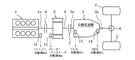
図1は、本発明のモード切り替え制御装置を適用可能なハイブリッド駆動装置を具えたフロントエンジン・リヤホイールドライブ式ハイブリッド車両のパワートレーンを示し、1はエンジン、2は駆動車輪(後輪)である。
図1に示すハイブリッド車両のパワートレーンにおいては、通常の後輪駆動車と同様にエンジン1の車両前後方向後方に自動変速機3をタンデムに配置し、エンジン1(クランクシャフト1a)からの回転を自動変速機3の入力軸3aへ伝達する軸4に結合してモータ/ジェネレータ5を設ける。
Hereinafter, embodiments of the present invention will be described in detail based on examples shown in the drawings.
FIG. 1 shows a power train of a front engine / rear wheel drive hybrid vehicle equipped with a hybrid drive device to which the mode switching control device of the present invention can be applied, where 1 is an engine and 2 is a drive wheel (rear wheel). .
In the power train of the hybrid vehicle shown in FIG. 1, the
モータ/ジェネレータ5は、モータとして作用したり、ジェネレータ(発電機)として作用するもので、エンジン1および自動変速機3間に配置する。
このモータ/ジェネレータ5およびエンジン1間に、より詳しくは、軸4とエンジンクランクシャフト1aとの間に第1クラッチ6を介挿し、この第1クラッチ6によりエンジン1およびモータ/ジェネレータ5間を切り離し可能に結合する。
ここで第1クラッチ6は、伝達トルク容量を連続的または段階的に変更可能なものとし、例えば、比例ソレノイドでクラッチ作動油流量およびクラッチ作動油圧を連続的に制御して伝達トルク容量を変更可能な湿式多板クラッチで構成する。
The motor /
More specifically, a
Here, the transmission torque capacity of the
モータ/ジェネレータ5および自動変速機3間に、より詳しくは、軸4と変速機入力軸3aとの間に第2クラッチ7を介挿し、この第2クラッチ7によりモータ/ジェネレータ5および自動変速機3間を切り離し可能に結合する。
第2クラッチ7も第1クラッチ6と同様、伝達トルク容量を連続的または段階的に変更可能なものとし、例えば、比例ソレノイドでクラッチ作動油流量およびクラッチ作動油圧を連続的に制御して伝達トルク容量を変更可能な湿式多板クラッチで構成する。
More specifically, a
Similarly to the
自動変速機3は、2003年1月、日産自動車(株)発行「スカイライン新型車(CV35型車)解説書」第C−9頁〜第C−22頁に記載されたと同じものとし、複数の変速摩擦要素(クラッチやブレーキ等)を選択的に締結したり解放することで、これら変速摩擦要素の締結・解放組み合わせにより伝動系路(変速段)を決定するものとする。
従って自動変速機3は、入力軸3aからの回転を選択変速段に応じたギヤ比で変速して出力軸3bに出力する。
この出力回転は、ディファレンシャルギヤ装置8により左右後輪2へ分配して伝達され、車両の走行に供される。
但し自動変速機3は、上記したような有段式のものに限られず、無段変速機であってもよいのは言うまでもない。
The
Therefore, the
This output rotation is distributed and transmitted to the left and right
However, it goes without saying that the
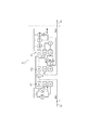
自動変速機3は、図4に示すごときもので、以下にその概略を説明する。
入出力軸3a,3bは同軸突き合わせ関係に配置し、これら入出力軸3a,3b 上にエンジン1(モータ/ジェネレータ5)の側から順次フロントプラネタリギヤ組Gf、センタープラネタリギヤ組Gm、およびリヤプラネタリギヤ組Grを載置して具え、これらを自動変速機3における遊星歯車変速機構の主たる構成要素とする。
The
The input /
エンジン1(モータ/ジェネレータ5)に最も近いフロントプラネタリギヤ組Gfは、フロントサンギヤSf 、フロントリングギヤRf 、これらに噛合するフロントピニオンPf 、および該フロントピニオンを回転自在に支持するフロントキャリアCf よりなる単純遊星歯車組とし、
次にエンジン1(モータ/ジェネレータ5)に近いセンタープラネタリギヤ組Gmは、センターサンギヤSm 、センターリングギヤRm 、これらに噛合するセンターピニオンPm 、および該センターピニオンを回転自在に支持するセンターキャリアCm よりなる単純遊星歯車組とし、
エンジン1(モータ/ジェネレータ5)から最も遠いリヤプラネタリギヤ組Grは、リヤサンギヤSr 、リヤリングギヤRr 、これらに噛合するリヤピニオンPr 、および該リヤピニオンを回転自在に支持するリヤキャリアCr よりなる単純遊星歯車組とする。
The front planetary gear set Gf closest to the engine 1 (motor / generator 5) is a simple planetary gear comprising a front sun gear Sf, a front ring gear Rf, a front pinion Pf meshing with the front sun gear Sf, and a front carrier Cf rotatably supporting the front pinion. A gear set,
Next, the center planetary gear set Gm close to the engine 1 (motor / generator 5) includes a center sun gear Sm, a center ring gear Rm, a center pinion Pm meshing with the center sun gear Sm, and a center carrier Cm that rotatably supports the center pinion. A planetary gear set,
The rear planetary gear set Gr farthest from the engine 1 (motor / generator 5) is a simple planetary gear set comprising a rear sun gear Sr, a rear ring gear Rr, a rear pinion Pr meshing with the rear sun gear Sr, and a rear carrier Cr that rotatably supports the rear pinion. To do.
遊星歯車変速機構の伝動経路(変速段)を決定する変速摩擦要素としては、フロントブレーキFr/B、インプットクラッチI/C、ハイ・アンド・ローリバースクラッチH&LR/C、ダイレクトクラッチD/C、リバースブレーキR/B、ロー・コーストブレーキLC/B、およびフォワードブレーキFWD/Bを設け、これらを3個のワンウェイクラッチ、つまり3速ワンウェイクラッチ3rd/OWC、1速ワンウェイクラッチ1st/OWCおよびフォワードワンウェイクラッチFWD/OWCとともに、以下のごとくプラネタリギヤ組Gf,Gm,Grの上記構成要素に相関させて自動変速機3の遊星歯車変速機構を構成する。
Front friction Fr / B, input clutch I / C, high-and-low reverse clutch H & LR / C, direct clutch D / C, reverse, as the transmission friction elements that determine the transmission path (speed stage) of the planetary gear transmission mechanism Brake R / B, low coast brake LC / B, and forward brake FWD / B are provided, and these are three one-way clutches: three-speed one-way clutch 3rd / OWC, one-speed one-way clutch 1st / OWC and forward one-way clutch Together with the FWD / OWC, the planetary gear transmission mechanism of the
フロントリングギヤRfは入力軸3aに結合し、センターリングギヤRmは、インプットクラッチI/Cにより適宜入力軸3aに結合可能とする。
フロントサンギヤSfは、3速ワンウェイクラッチ3rd/OWCを介してエンジン1の回転方向と逆の方向へ回転しないようにすると共に、3速ワンウェイクラッチ3rd/OWCに対し並列的に配置したフロントブレーキFr/Bにより適宜固定可能にする。
フロントキャリアCfおよびリヤリングギヤRrを相互に結合し、センターリングギヤRmおよびリヤキャリアCrを相互に結合する。
The front ring gear Rf is coupled to the
The front sun gear Sf is prevented from rotating in the direction opposite to the rotation direction of the
Front carrier Cf and rear ring gear Rr are coupled to each other, and center ring gear Rm and rear carrier Cr are coupled to each other.
センターキャリアCmは出力軸3bに結合し、センターサンギヤSmおよびリヤサンギヤSr間は、1速ワンウェイクラッチ1st/OWCを介してセンターサンギヤSmがリヤサンギヤSrに対しエンジン1の回転方向と逆の方向へ回転しないようにすると共に、ハイ・アンド・ローリバースクラッチH&LR/CによりセンターサンギヤSmおよびリヤサンギヤSrを相互に結合可能とする。
The center carrier Cm is coupled to the
リヤサンギヤSrおよびリヤキャリアCr間をダイレクトクラッチD/Cにより結合可能とし、リヤキャリアCrをリバースブレーキR/Bにより適宜固定可能とする。
センターサンギヤSmは更に、フォワードブレーキFWD/BおよびフォワードワンウェイクラッチFWD/OWCにより、フォワードブレーキFWD/Bの締結状態でエンジン1の回転方向と逆の方向へ回転しないようにすると共に、ロー・コーストブレーキLC/Bにより適宜固定可能にし、これがためロー・コーストブレーキLC/BをフォワードブレーキFWD/BおよびフォワードワンウェイクラッチFWD/OWCに対し並列的に設ける。
The rear sun gear Sr and the rear carrier Cr can be coupled by a direct clutch D / C, and the rear carrier Cr can be appropriately fixed by a reverse brake R / B.
The center sun gear Sm is further prevented by the forward brake FWD / B and the forward one-way clutch FWD / OWC from rotating in the reverse direction of the
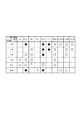
上記遊星歯車変速機構の動力伝達列は、7個の変速摩擦要素Fr/B,I/C,H&LR/C,D/C,R/B,LC/B,FWD/B、および3個のワンウェイクラッチ3rd/OWC,1st/OWC,FWD/OWCの図5に〇印および●印(エンジンブレーキ時)で示す選択的係合により、前進第1速(1st)、前進第2速(2nd)、前進第3速(3rd)、前進第4速(4th)および前進第5速(5th)の前進変速段と、後退変速段(Rev )とを得ることができる。 The power transmission train of the planetary gear transmission mechanism has seven shift friction elements Fr / B, I / C, H & LR / C, D / C, R / B, LC / B, FWD / B, and three one-way. With the selective engagement shown in Fig. 5 for clutches 3rd / OWC, 1st / OWC, FWD / OWC as indicated by ◯ and ● (when engine braking), forward first speed (1st), forward second speed (2nd), The third forward speed (3rd), the fourth forward speed (4th), the fifth forward speed (5th), and the reverse speed stage (Rev) can be obtained.
上記した自動変速機3を具える図1のパワートレーンにおいては、停車状態からの発進時などを含む低負荷・低車速時に用いられる電気走行(EV)モードが要求される場合、第1クラッチ6を解放し、第2クラッチ7を締結し、自動変速機3を動力伝達状態にする。
In the power train of FIG. 1 including the
この状態でモータ/ジェネレータ5を駆動すると、当該モータ/ジェネレータ5からの出力回転のみが変速機入力軸3aに達することとなり、自動変速機3が当該入力軸3aへの回転を、選択中の変速段に応じ変速して変速機出力軸3bより出力する。
変速機出力軸3bからの回転はその後、ディファレンシャルギヤ装置8を経て後輪2に至り、車両をモータ/ジェネレータ5のみによって電気走行(EV走行)させることができる。
When the motor /
Then, the rotation from the
高速走行時や、大負荷走行時や、バッテリの持ち出し可能電力が少ない時などで用いられるハイブリッド走行(HEV走行)モードが要求される場合、第1クラッチ6および第2クラッチ7をともに締結し、自動変速機3を動力伝達状態にする。
この状態では、エンジン1からの出力回転、または、エンジン1からの出力回転およびモータ/ジェネレータ5からの出力回転の双方が変速機入力軸3aに達することとなり、自動変速機3が当該入力軸3aへの回転を、選択中の変速段に応じ変速して、変速機出力軸3bより出力する。
変速機出力軸3bからの回転はその後、ディファレンシャルギヤ装置8を経て後輪2に至り、車両をエンジン1およびモータ/ジェネレータ5の双方によってハイブリッド走行(HEV走行)させることができる。
When hybrid driving (HEV driving) mode used when driving at high speeds, during heavy loads, or when the amount of power that can be taken out by the battery is low, both the
In this state, the output rotation from the
The rotation from the
かかるHEV走行中において、エンジン1を最適燃費で運転させるとエネルギーが余剰となる場合、この余剰エネルギーによりモータ/ジェネレータ5を発電機として作動させることで余剰エネルギーを電力に変換し、この発電電力をモータ/ジェネレータ5のモータ駆動に用いるよう蓄電しておくことでエンジン1の燃費を向上させることができる。
In such HEV traveling, if the
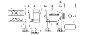
なお図1では、参考例として、モータ/ジェネレータ5および駆動車輪2を切り離し可能に結合する第2クラッチ7を、モータ/ジェネレータ5および自動変速機3間に介在させたが、
他の参考例として、図2に示すように、第2クラッチ7を自動変速機3およびディファレンシャルギヤ装置8間に介在させても、同様に機能させることができる。
In FIG. 1, as a reference example, the
As another reference example, as shown in FIG. 2, even if the
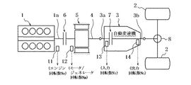
また、図1および図2では第2クラッチ7として専用のものを自動変速機3の前、若しくは、後に追加することとしたが、
この代わりに第2クラッチ7として、図3に示すごとく自動変速機3内に既存する前進変速段選択用の変速摩擦要素または後退変速段選択用の変速摩擦要素を流用するようにしてもよい。
第2クラッチ7として流用する自動変速機3の変速摩擦要素については後述する。
この場合、第2クラッチ7が前記したモード選択機能を果たすのに加えて、この機能を果たすよう締結される時に自動変速機を動力伝達状態にすることとなり、専用の第2クラッチが不要でコスト上大いに有利である。
In addition, in FIG. 1 and FIG. 2, a dedicated
Instead, as the
The shift friction element of the
In this case, in addition to the
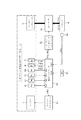
図1〜3に示すハイブリッド車両のパワートレーンを成すエンジン1、モータ/ジェネレータ5、第1クラッチ6、および第2クラッチ7は、図6に示すようなシステムにより制御する。
なお以下では、パワートレーンが図3に示すようなものである(第2クラッチ7として自動変速機3内に既存の変速摩擦要素を流用したもの)である場合につき説明を展開するものとする。
The
In the following description, it is assumed that the power train is as shown in FIG. 3 (existing speed change friction element in the
図6の制御システムは、パワートレーンの動作点を統合制御する統合コントローラ20を具え、パワートレーンの動作点を、目標エンジントルクtTeと、目標モータ/ジェネレータトルクtTm(目標モータ/ジェネレータ回転数tNmでもよい)と、第1クラッチ6の目標伝達トルク容量tTc1(第1クラッチ指令圧tPc1)と、第2クラッチ7の目標伝達トルク容量tTc2(第2クラッチ指令圧tPc2)とで規定する。
The control system of FIG. 6 includes an
統合コントローラ20には、上記パワートレーンの動作点を決定するために、
エンジン回転数Neを検出するエンジン回転センサ11からの信号と、
モータ/ジェネレータ回転数Nmを検出するモータ/ジェネレータ回転センサ12からの信号と、
変速機入力回転数Niを検出する入力回転センサ13からの信号と、
変速機出力回転数Noを検出する出力回転センサ14からの信号と、
エンジン1の要求負荷状態を表すアクセルペダル踏み込み量(アクセル開度APO)を検出するアクセル開度センサ15からの信号と、
モータ/ジェネレータ5用の電力を蓄電しておくバッテリ9の蓄電状態SOC(持ち出し可能電力)を検出する蓄電状態センサ16からの信号とを入力する。
In order to determine the operating point of the power train, the
A signal from the
A signal from the motor /
A signal from the
A signal from the
A signal from an accelerator opening sensor 15 for detecting an accelerator pedal depression amount (accelerator opening APO) representing a required load state of the
A signal from a
なお、上記したセンサのうち、エンジン回転センサ11、モータ/ジェネレータ回転センサ12、入力回転センサ13、および出力回転センサ14はそれぞれ、図1〜3に示すように配置することができる。
Among the sensors described above, the
統合コントローラ20は、上記入力情報のうちアクセル開度APO、バッテリ蓄電状態SOC、および変速機出力回転数No(車速VSP)から、運転者が希望している車両の駆動力を実現可能な運転モード(EVモード、HEVモード)を選択すると共に、目標エンジントルクtTe、目標モータ/ジェネレータトルクtTm(目標モータ/ジェネレータ回転数tNmでもよい)、目標第1クラッチ伝達トルク容量tTc1(第1クラッチ指令圧tPc1)、および目標第2クラッチ伝達トルク容量tTc2(第2クラッチ指令圧tPc2)をそれぞれ演算する。
目標エンジントルクtTeはエンジンコントローラ21に供給され、目標モータ/ジェネレータトルクtTm(目標モータ/ジェネレータ回転数tNmでもよい)はモータ/ジェネレータコントローラ22に供給される。
The
The target engine torque tTe is supplied to the
エンジンコントローラ21は、エンジントルクTeが目標エンジントルクtTeとなるようエンジン1を制御し、
モータ/ジェネレータコントローラ22はモータ/ジェネレータ5のトルクTm(または回転数Nm)が目標モータ/ジェネレータトルクtTm(または目標モータ/ジェネレータ回転数tNm)となるよう、バッテリ9およびインバータ10を介してモータ/ジェネレータ5を制御する。
統合コントローラ20は、目標第1クラッチ伝達トルク容量tTc1(第1クラッチ指令圧tPc1)および目標第2クラッチ伝達トルク容量tTc2(第2クラッチ指令圧tPc2)に対応したソレノイド電流を第1クラッチ6および第2クラッチ7の油圧制御ソレノイド(図示せず)に供給し、第1クラッチ6の伝達トルク容量Tc1(第1クラッチ圧Pc1)が目標伝達トルク容量tTc1(第1クラッチ指令圧tPc1)に一致するよう、また、第2クラッチ7の伝達トルク容量Tc2(第2クラッチ圧Pc2)が目標第2クラッチ伝達トルク容量tTc2(第2クラッチ指令圧tPc2)に一致するよう、第1クラッチ6および第2クラッチ7を個々に締結力制御する。
The
The motor /
The
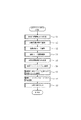
統合コントローラ20は、上記した運転モード(EVモード、HEVモード)の選択、そして目標エンジントルクtTe、目標モータ/ジェネレータトルクtTm(目標モータ/ジェネレータ回転数tNmでもよい)、目標第1クラッチ伝達トルク容量tTc1(第1クラッチ指令圧tPc1)、および目標第2クラッチ伝達トルク容量tTc2(第2クラッチ指令圧tPc2)の演算を、図7に示すメインルーチンにより実行する。
The
先ずステップS1において、予定の到達目標駆動力マップを用いて、アクセル開度APOおよび車速VSPから、定常的な到達目標駆動力tFo0を演算する。
次のステップS2においては、予定の変速マップをもとにアクセル開度APOおよび車速VSPから目標変速段SHIFTを決定し、これをステップS9で自動変速機3の変速制御部(図示せず)へ指令して自動変速機3を目標変速段SHIFTへと変速させる。
First, in step S1, a steady attainment target driving force tFo0 is calculated from the accelerator opening APO and the vehicle speed VSP using a planned attainment target driving force map.
In the next step S2, the target shift stage SHIFT is determined from the accelerator opening APO and the vehicle speed VSP based on the planned shift map, and this is transferred to the shift control unit (not shown) of the
ステップS3においては、予定の目標運転モード領域マップを用いて、アクセル開度APOおよび車速VSPから目標とする運転モード(EVモード、HEVモード)を決定する。
目標運転モードとして通常、高負荷(大アクセル開度)・高車速時はHEVモードをあてがい、低負荷・低車速時はEVモードをあてがうように上記の目標運転モード領域マップを定めるのが普通である。
In step S3, the target operation mode (EV mode, HEV mode) is determined from the accelerator opening APO and the vehicle speed VSP using the planned target operation mode region map.
Normally, the target operation mode area map above is set so that the HEV mode is applied at high loads (large accelerator opening) and high vehicle speeds, and the EV mode is applied at low loads and low vehicle speeds. is there.
次のステップS4においては、現在の運転モードと上記目標運転モードとの対比により、運転モード遷移演算を以下のごとくに行う。
現在の運転モードと目標運転モードとが一致していれば、現在の運転モードEVモードまたはHEVモードを保持するよう指令し、
現在の運転モードがEVモードで、目標運転モードがHEVモードであれば、EVモードからHEVモードへのモード切り換えを指令し、
現在の運転モードがHEVモードで、目標運転モードがEVモードであれば、HEVモードからEVモードへのモード切り換えを指令する。
そして、これらの指令をステップS9で出力することにより、指令通りにモード保持や、モード切り換えを行わせる。
In the next step S4, the operation mode transition calculation is performed as follows by comparing the current operation mode with the target operation mode.
If the current operation mode and the target operation mode match, command to maintain the current operation mode EV mode or HEV mode,
If the current operation mode is EV mode and the target operation mode is HEV mode, command to switch the mode from EV mode to HEV mode,
If the current operation mode is the HEV mode and the target operation mode is the EV mode, the mode is switched from the HEV mode to the EV mode.
Then, by outputting these commands in step S9, mode holding or mode switching is performed as instructed.
ステップS5においては、現在の駆動力から、ステップS1で求めた到達目標駆動力tFo0へ、所定の味付けをもった応答で移行するのに必要な時々刻々の過渡目標駆動力tFoを演算する。
この演算に当たっては例えば、到達目標駆動力tFo0を所定時定数のローパスフィルタに通過させて得られる出力を過渡目標駆動力tFoとすることができる。
In step S5, the transient target driving force tFo is calculated every moment necessary for shifting from the current driving force to the ultimate target driving force tFo0 obtained in step S1 with a predetermined seasoning response.
In this calculation, for example, an output obtained by passing the ultimate target driving force tFo0 through a low-pass filter having a predetermined time constant can be used as the transient target driving force tFo.
ステップS6においては、運転モード(EVモード、HEVモード)や、モード切り替えに応じて、過渡目標駆動力tFoと、駆動車輪2のタイヤ有効半径Rtと、ファイナルギヤ比ifと、現在の選択変速段により決まる自動変速機3のギヤ比iGと、自動変速機3の入力回転数Niと、エンジン回転数Neと、バッテリ蓄電状態SOC(持ち出し可能電力)に応じた目標放電電力tPとから、モータ/ジェネレータ5との共働により、若しくは単独で、過渡目標駆動力tFoを達成するのに必要な目標エンジントルクtTeを求め、
このようにして決定した目標エンジントルクtTeをステップS9において、図6のエンジンコントローラ21に指令し、エンジンコントローラ21はエンジン1を目標エンジントルクtTeが実現されるよう制御する。
In step S6, depending on the operation mode (EV mode, HEV mode) and mode switching, the transient target driving force tFo, the tire effective radius Rt of the
The target engine torque tTe determined in this way is commanded to the
ステップS7においては、運転モード(EVモード、HEVモード)や、モード切り替えに応じて、過渡目標駆動力tFoを達成するのに必要な、または、モード切り替えを遂行させるのに必要な第1クラッチ6および第2クラッチ7の目標伝達トルク容量tTc1,tTc2(クラッチ指令圧tPc1,tPc2)を求め、
このようにして決定した第1クラッチ6および第2クラッチ7の目標伝達トルク容量tTc1,tTc2(クラッチ指令圧tPc1,tPc2)をステップS9において、図6の第1クラッチ6および第2クラッチ7に指令し、第1クラッチ6および第2クラッチ7を目標伝達トルク容量tTc1,tTc2となるよう締結力制御する。
In step S7, the
The target transmission torque capacities tTc1, tTc2 (clutch command pressures tPc1, tPc2) of the
ステップS8においては、運転モード(EVモード、HEVモード)や、モード切り替えに応じて、過渡目標駆動力tFoと、駆動車輪2のタイヤ有効半径Rtと、ファイナルギヤ比ifと、現在の選択変速段により決まる自動変速機3のギヤ比iGと、自動変速機3の入力回転数Niと、エンジン回転数Neと、バッテリ蓄電状態SOC(持ち出し可能電力)に応じた目標放電電力tPとから、エンジン1との共働により、若しくは単独で、過渡目標駆動力tFoを達成するのに必要な目標モータ/ジェネレータトルクtTmを求め、
このようにして決定した目標モータ/ジェネレータトルクtTmをステップS9において、図6のモータ/ジェネレータコントローラ22に指令し、モータ/ジェネレータコントローラ22はモータ/ジェネレータ5を目標モータ/ジェネレータトルクtTmが実現されるよう制御する。
In step S8, depending on the operation mode (EV mode, HEV mode) and mode switching, the transient target driving force tFo, the tire effective radius Rt of the
The target motor / generator torque tTm thus determined is commanded to the motor /
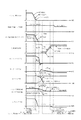
以上は一般的なハイブリッド車両のパワートレーン駆動力制御であるが、本発明が狙いとするHEV→EVモード切り替え制御を、図8に示すごとくアクセルペダルの釈放でアクセル開度APOが低下され、これに伴ってHEV→EVモード切り替え指令が発せられると共に自動変速機3が4速から5速へアップシフトされる場合につき、以下に説明する。
The above is the powertrain driving force control of a general hybrid vehicle. In the HEV → EV mode switching control aimed by the present invention, the accelerator pedal opening APO is reduced by releasing the accelerator pedal as shown in FIG. A description will now be given of the case where the HEV → EV mode switching command is issued and the
なお、HEV→EVモード切り替えは前記したとおり、第1クラッチ6および第2クラッチ7を締結してエンジン1およびモータ/ジェネレータ5からの動力により車輪2を駆動するハイブリッド走行(HEV)モードから、第1クラッチ6を解放すると共にエンジン1を停止してモータ/ジェネレータ5からの動力のみにより車輪2を駆動する電気走行(EV)モードへの切り替えであるため、第1クラッチ6を解放すると共にエンジン1を停止して当該HEV→EVモード切り替えが遂行される。
また、自動変速機3の上記4速から5速へのアップシフトは、図5の締結論理図に矢印を付して示すごとく、締結状態のダイレクトクラッチD/Cを解放させる(これを解放要素と称する)と共に、解放状態のフロントブレーキFr/Bを締結させる(これを締結要素と称する)ことにより達成されるため、
ここではダイレクトクラッチD/C(解放要素)を図3の第2クラッチ7として用い、図8では、その指令圧をtPc2により、また、その実圧をPc2によりそれぞれ示した。
As described above, the HEV → EV mode is switched from the hybrid travel (HEV) mode in which the
Further, the upshift of the
Here, the direct clutch D / C (release element) is used as the
図8では更に、フロントブレーキFr/B(締結要素)の指令圧をtPcにより、また、その実圧をPcにより、また、その伝達トルク容量をTcによりそれぞれ示した。
図8ではその他に、図5から明らかなごとく上記4速から5速へのアップシフト中も締結状態を保つハイ・アンド・ローリバースクラッチH&LR/Cの伝達トルク容量を、エンジン1のトルクTe、モータ/ジェネレータ5のトルクTm、エンジン回転数Ne、モータ/ジェネレータ回転数Nm、および変速機出力トルクToと共に併記し、
図3における第1クラッチ6の指令圧をtPc1により、また、その実圧をPc1により、また、その伝達トルク容量をTc1によりそれぞれ示した。
ただし第1クラッチ6は、常態では締結されてその伝達トルク容量Tc1を最大値にされており、その指令圧tPc1に向かうよう制御される実圧Pc1の上昇につれ伝達トルク容量Tc1を低下されるものとする。
Further, in FIG. 8, the command pressure of the front brake Fr / B (engagement element) is indicated by tPc, the actual pressure thereof is indicated by Pc, and the transmission torque capacity thereof is indicated by Tc.
In addition to FIG. 8, as clearly shown in FIG. 5, the transmission torque capacity of the high and low reverse clutch H & LR / C that maintains the engaged state even during the upshift from the fourth speed to the fifth speed is shown as the torque Te, Along with the torque Tm of the motor /
The command pressure of the
However, the
図8に示すアクセル開度APO(要求駆動力)の低下で4→5アップシフト指令が発せられる瞬時t1に、今回第2クラッチ7として用いるダイレクトクラッチD/C(解放要素)の指令圧tPc2を、若干の応答遅れはあるものの理論上は即座に0にする。
これによりダイレクトクラッチD/C(解放要素)の実圧Pc2は、ハードウェア上の動作遅れををもって指令圧tPc2に追従するよう制御され、ダイレクトクラッチD/C(解放要素)は4→5アップシフト指令が発せられる瞬時t1からできるだけ早期に解放させる。
一方で、フロントブレーキFr/B(締結要素)の締結を未だ実行させないことにより、自動変速機3を動力伝達不能な中立状態にしておく。
The command pressure tPc2 of the direct clutch D / C (release element) used this time as the
As a result, the actual pressure Pc2 of the direct clutch D / C (release element) is controlled to follow the command pressure tPc2 with a delay in hardware, and the direct clutch D / C (release element) is upshifted by 4 to 5 Release as soon as possible from the instant t1 when the command is issued.
On the other hand, the front transmission Fr / B (engagement element) is not yet engaged, so that the
図8に示すアクセル開度APO(要求駆動力)の更なる低下で、瞬時t2にHEV→EVモード切り替え指令が発せられ、瞬時t3にアクセル開度APO=0の判定(アイドル判定)がなされるが、
HEV→EVモード切り替え指令瞬時t2から所定時間TM1が経過する瞬時t4に、第1クラッチ6の指令圧tPc1を、若干の応答遅れはあるものの理論上は即座に最大値にする。
これにより第1クラッチ6の実圧Pc1は、ハードウェア上の動作遅れををもって指令圧tPc1に追従するよう制御され、第1クラッチ6は伝達トルク容量Tc1を図示のごとくに低下され、図示のスリップ開始点を経て遂には解放される。
When the accelerator opening APO (required driving force) shown in FIG. 8 further decreases, the HEV → EV mode switching command is issued at instant t2, and the accelerator opening APO = 0 is determined (idle determination) at instant t3. But,
The command pressure tPc1 of the
As a result, the actual pressure Pc1 of the
HEV→EVモード切り替え指令瞬時t2から所定時間TM2が経過する瞬時t5より、エンジントルクTeをそれまでのアクセル開度APOに応じた制御状態から、フューエルカット(燃料供給停止)によるエンジン停止操作で一気に低下させ、エンジン回転数Neの経時変化により示すごとくにエンジンを停止させる。
なお上記の所定時間TM1,TM2は、エンジン1の上記停止によりエンジン運転中のエンジントルクTeが消失した(図8の正側エンジントルクが消失した)後に第1クラッチ6の解放が行われるような相関関係を持った予定時間とする(図8に第1クラッチ6の解放判定瞬時t6、および第1クラッチ6の解放瞬時t7を示した)。
HEV → EV mode switching command From the instant t5 when the predetermined time TM2 has elapsed from the instant t2, the engine torque Te is immediately stopped by the engine stop operation by fuel cut (fuel supply stop) from the control state according to the accelerator opening APO Decrease and stop the engine as indicated by the change in engine speed Ne over time.
Note that the predetermined clutches TM1 and TM2 are such that the
HEV→EVモード切り替え指令瞬時t2から所定時間TM2が経過する瞬時t5より、つまりこの瞬時t5から上記のごとくに行われるエンジン停止操作と並行的に、自動変速機3の4→5アップシフトに伴う入力側回転数の低下をモータ/ジェネレータ5により前もって生起させる変速ショック防止用の回転合わせ制御を行う。
この回転合わせ制御は、その開始時t5から、変速ショック防止上予め定めた目標変速時間(図8参照)が経過する瞬時t8までの間に、モータ/ジェネレータ5の回転数Nmを変速前回転数(図8に4速回転数として示した)から変速後回転数(図8に5速回転数として示した)へと低下させる、モータ/ジェネレータ5の回転数(Nm)制御であり、この回転数Nmが変速後回転数(図8に5速回転数として示した)に対し余裕代をもって接近した瞬時t8に終了させる。
From the instant t5 when the predetermined time TM2 elapses from the HEV → EV mode switching command instant t2, that is, in parallel with the engine stop operation performed as described above from this instant t5, accompanying the 4 → 5 upshift of the
In this rotation matching control, the rotation speed Nm of the motor /
4→5アップシフト時の締結要素であるフロントブレーキFr/Bの指令圧tPcは、エンジン停止指令瞬時(モータ/ジェネレータ5の回転合わせ制御開始瞬時)t5より図示のごとくに上昇させるが、モータ/ジェネレータ5の回転合わせ制御終了瞬時t8までは、実圧PcがフロントブレーキFr/B(締結要素)をリターンスプリングに抗してロスストロークさせる程度の小さな値とし、これによりフロントブレーキFr/B(締結要素)を締結開始直前状態に保ってその締結動作遅れをできるだけ少なくする。
The command pressure tPc of the front brake Fr / B, which is the engagement element at the time of the 4 → 5 upshift, rises as shown in the figure from the engine stop command moment (motor /
そしてモータ/ジェネレータ5の回転合わせ制御終了瞬時t8にフロントブレーキFr/B(締結要素)の指令圧tPcを最大値にして、ハードウェア上の動作遅れをもってこれに追従するよう制御される実圧Pcの上昇によりフロントブレーキFr/B(締結要素)の伝達トルク容量Tcを図示のごとくに増大させる。
これによるフロントブレーキFr/B(締結要素)の締結は、前記したダイレクトクラッチD/C(解放要素)の解放とにより、自動変速機3を4速から5速へとアップシフトさせる。
Then, the actual pressure Pc is controlled so that the command pressure tPc of the front brake Fr / B (fastening element) is maximized at the moment t8 when the rotation matching control of the motor /
When the front brake Fr / B (engagement element) is engaged, the
かかるフロントブレーキFr/B(締結要素)の締結進行、つまり4速から5速へのアップシフトの進行により、モータ/ジェネレータ5はモータトルクTmの経時変化から明らかなようにフリクショントルクを低下されるが、モータ/ジェネレータ5の回転合わせ制御終了瞬時t8からの経過時間が所定時間TM3となる瞬時t9より、モータ/ジェネレータ5のトルクTmをHEV→EVモード切り替え後の目標駆動トルクとなすためのモータトルク制御を行わせる。
ここで所定時間TM3は、モータ/ジェネレータ5のフリクショントルクTmが、フロントブレーキFr/B(締結要素)の締結進行、つまり4速から5速へのアップシフトの進行により消失するのに要する時間として予め設定する予定時間である。
As the front brake Fr / B (engagement element) is engaged, that is, the upshift from the 4th speed to the 5th speed is performed, the motor /
Here, the predetermined time TM3 is the time required for the friction torque Tm of the motor /
かかるモータトルク制御により、モータ/ジェネレータ5のトルクTmがHEV→EVモード切り替え後の目標駆動トルクとなる瞬時t10に、自動変速機3の4→5アップシフトを伴ったHEV→EVモード切り替えが終了するが、
アクセルペダルの釈放によるアクセル開度APO=0に起因して上記HEV→EVモード切り替え後の目標駆動トルクが負値(エンジンブレーキ要求)であることから、瞬時t9以後モータ/ジェネレータ5はエネルギーの回生により発電を行う発電機として機能する。
With this motor torque control, the HEV → EV mode switching with the 4 → 5 upshift of the
Since the target drive torque after switching the HEV → EV mode is negative (engine brake request) due to the accelerator opening APO = 0 due to the release of the accelerator pedal, the motor /
なお、自動変速機3の4→5アップシフト中も締結状態を保つハイ・アンド・ローリバースクラッチH&LR/Cの伝達トルク容量は図8に示すごとく、モータ/ジェネレータ5のトルクTmがHEV→EVモード切り替え後の目標駆動トルクとなるHEV→EVモード切り替え終了瞬時t10を境に、それよりも前ではHEVモードに呼応してエンジン1およびモータ/ジェネレータ5からのトルクを伝達可能なトルク容量に制御し、瞬時t10よりも後ではEVモードに呼応してモータ/ジェネレータ5からのトルクを伝達可能なトルク容量に制御する。
Note that the transmission torque capacity of the high and low reverse clutch H & LR / C that maintains the engaged state during the 4 → 5 upshift of the
上記した本実施例のHEV→EVモード切り替え制御によれば、以下の作用効果が得られる。
つまり、HEVモードから、エンジン1の停止および第1クラッチ6の解放により、EVモードへのモード切り替えを行うに際し、第2クラッチ7(ダイレクトクラッチD/C)の締結トルク容量(図8の実圧Pc2で決まる)を、この第2クラッチ7がエンジン停止時のショック(図8にハッチングを付して示したエンジントルクTeの変化)を吸収し得るよう低下させた状態で(図8では、第2クラッチであるダイレクトクラッチD/Cの締結トルク容量を0にした状態で)、上記モード切り替え時のエンジン1の停止および第1クラッチ6の解放を行わせるため、
第1クラッチ6の解放タイミングがバラツキによりエンジン1の停止タイミングより遅れて、第1クラッチ1の伝達トルク容量Tc1がエンジントルクTeよりも大きい間にエンジン1を停止させることとなった場合でも、エンジン停止時のトルク変動(図8にハッチングを付して示したエンジントルクTeの変化)が第1クラッチ6を経て後方の駆動車輪2へ向かう途中に存在する第2クラッチ7(ダイレクトクラッチD/C)のスリップにより吸収され、図8の0に保たれる出力トルクToの経時変化から明らかなようにエンジン停止ショックの発生を防止して、このショックに関する前記した従来の問題を回避することができる。
According to the HEV → EV mode switching control of the present embodiment described above, the following operational effects can be obtained.
That is, when switching the mode from the HEV mode to the EV mode by stopping the
Even when the release timing of the
また、かようにエンジン停止ショックが回避されることで、この問題解決のためのモータ/ジェネレータ5の前記したトルク補償制御が不要であり、当該制御時に決定すべきトルク補償タイミングおよびトルク補償量の決定に煩わされることもなく、上記したエンジン停止ショック防止機能を確実に得ることができる。
Further, by avoiding the engine stop shock in this way, the torque compensation control of the motor /
なお、かかるモータ/ジェネレータ5のトルク補償制御が必要であると、上記のHEV→EVモード切り替えが自動変速機の変速を伴うものである場合、従って、変速ショック対策上モータ/ジェネレータの回転合わせ制御が必要である場合、モータ/ジェネレータをトルク補償制御しつつ回転合わせ制御しなければならなくなるが、
これら制御を同時に遂行することが不可能で、優先順位の高い方から順次に遂行することとなり、モード切り替え応答を著しく悪化させるという新たな問題を生ずるところながら、
本実施例においては上記の通り、モータ/ジェネレータ5の上記トルク補償制御なしにエンジン停止ショック防止機能を達成し得ることから、モータ/ジェネレータ5を変速ショック対策用に回転合わせ制御するだけでよく、上記の新たな問題を生ずることもないし、モータ/ジェネレータ5による変速ショック対策用回転合わせ制御の制御性を向上させることができる。
When torque compensation control of the motor /
While it is impossible to perform these controls at the same time, it will be performed sequentially from the one with the highest priority, causing a new problem that the mode switching response is remarkably deteriorated.
In this embodiment, as described above, since the engine stop shock prevention function can be achieved without the torque compensation control of the motor /
ところで、第1クラッチ6の解放タイミングがバラツキによりエンジン1の停止タイミングより早くて、エンジン1がエンジン停止操作(本実施例ではフューエルカット)中であっても未だ停止に至らず正駆動トルクを発生している間に第1クラッチ6の伝達トルク容量がエンジントルクTeよりも小さくなる場合、エンジンが正駆動トルクにより空吹けを生じてしまい、運転者に違和感を与えるという問題を生ずるが、
本実施例においては前記したごとく、当該エンジンの空吹けに関する問題以外の問題が全て解消されているため、上記のHEV→EVモード切り替えをかかるエンジンの空吹けが生じないような図8に示すごとき態様で実行するだけで、前記した全ての諸問題を解消することができることとなり、簡単な制御で全ての問題を解消することができる。
By the way, the disengagement timing of the
In the present embodiment, as described above, since all the problems other than the problem related to the engine blowing are solved, the HEV → EV mode switching is performed as shown in FIG. All the above-mentioned problems can be solved only by executing in the mode, and all the problems can be solved by simple control.
また本実施例においては、第2クラッチ7(ダイレクトクラッチD/C)の締結トルク容量(図8の実圧Pc2で決まる)を、この第2クラッチ7がエンジン停止時のショック(図8にハッチングを付して示したエンジントルクTeの変化)を吸収し得るよう低下させた状態で(図8では、第2クラッチであるダイレクトクラッチD/Cの締結トルク容量を0にした状態で)、前記4→5アップシフト時のモータ/ジェネレータ5による変速ショック対策用回転合わせ制御を行うため、
このモータ/ジェネレータ5による回転合わせ制御を、出力トルクToに関係なく、また、モータ/ジェネレータトルクTmに関係なく行うことができ、従って、エンジン停止動作(モード切り替え)と、回転合わせ制御(変速制御)とを同時並行させ得て、自動変速機3の変速を伴うHEV→EVモード切り替えといえども、これを短時間で完遂させることができる。
Further, in this embodiment, the engagement torque capacity of the second clutch 7 (direct clutch D / C) (determined by the actual pressure Pc2 in FIG. 8) is applied to the shock when the
The rotation matching control by the motor /
更に本実施例においては、HEV→EVモード切り替え指令時t2からの経過時間を計測してこの経過時間(所定時間TM2,TM1)に基づき、エンジン1の停止によりエンジン運転中のエンジントルクTeが消失した後に第1クラッチ6の解放を行わせるため、
エンジン1がエンジン停止操作(本実施例ではフューエルカット)中であっても未だ停止に至らず正駆動トルクを発生している間に第1クラッチ6の伝達トルク容量がエンジントルクTeよりも小さくなることがなく、従って、エンジンが正駆動トルクにより空吹けを生じて運転者に違和感を与えるという問題を確実に解消することができる。
Furthermore, in this embodiment, the elapsed time from the HEV → EV mode switching command t2 is measured, and based on this elapsed time (predetermined times TM2, TM1), the engine torque Te during engine operation disappears due to the
Even if the
なお上記では、自動変速機3の4→5アップシフトが図5の締結論理から明らかなようにワンウェイクラッチを介することのない変速であることから、
HEV→EVモード切り替え指令時t2からの経過時間(所定時間TM2,TM1)に基づき、エンジン1の停止によりエンジン運転中のエンジントルクTeが消失した後に第1クラッチ6の解放を行わせるようにしてエンジンの空吹けを防止したが、
変速に際し締結される変速摩擦要素の締結によって発生する伝動系に、駆動車輪2からエンジン1への逆駆動を空転により禁止するワンウェイクラッチ(逆駆動禁止要素)が存在していて、この要素が空転している場合は、エンジンの空吹けを生ずることがないため、前記エンジンの停止および第1クラッチの解放を、HEV→EVモード切り替え指令時t2に直ちに開始させ、これによりモード切り替えの応答性と、エンジンの燃費向上とを実現するのがよい。
In the above, the 4 → 5 upshift of the
Based on the elapsed time from the HEV → EV mode switching command t2 (predetermined times TM2, TM1), the
There is a one-way clutch (reverse drive prohibition element) that inhibits reverse drive from the
なお上記では、自動変速機3の4→5アップシフトがダイレクトクラッチD/Cを締結状態から解放させると共に、ハイ・アンド・ローリバースクラッチH&LR/Cを解放状態から締結させる摩擦要素の掛け替えにより行われることから、
解放側変速摩擦要素であるダイレクトクラッチD/Cを第2クラッチ7(図3参照)として用い、第2クラッチ7を図1および図2に示すように新設する必要がないようにしたため、コスト上およびスペース上大いに有利である。
In the above, the 4 → 5 upshift of the
The direct clutch D / C, which is the disengagement side frictional element, is used as the second clutch 7 (see Fig. 3), and the
ところで、摩擦要素の掛け替えに依らない自動変速機3の変速を伴うHEV→EVモード切り替え時や、変速を伴わないHEV→EVモード切り替え時においては、当該モード切り替え中に自動変速機を伝動状態に維持するための変速摩擦要素を図3における第2クラッチ7として用いることで、第2クラッチ7を図1および図2に示すように新設する必要がないようにして同様の作用効果を奏することができる。
一例としては、自動変速機3の締結論理を示す図5から明らかなように、ハイ・アンド・ローリバースクラッチH&LR/Cが2速以外の全ての変速段で締結状態にされることから、これを図3の第2クラッチとして用い、HEV→EVモード切り替え中にこれを解放、若しくは、その伝達トルク容量を低下させることで、前記した作用効果を達成することができる。
By the way, at the time of HEV → EV mode switching that involves shifting of the
As an example, as is clear from FIG. 5 showing the engagement logic of the
1 エンジン
2 駆動車輪(後輪)
3 自動変速機
Gf フロントプラネタリギヤ組
Gm センタープラネタリギヤ組
Gr リヤプラネタリギヤ組
Fr/B フロントブレーキ
I/C インプットクラッチ
H&LR/C ハイ・アンド・ローリバースクラッチ
D/C ダイレクトクラッチ(第2クラッチ)
R/B リバースブレーキ
LC/B ロー・コーストブレーキ
FWD/B フォワードブレーキ
3rd/OWC 3速ワンウェイクラッチ
1st/OWC 1速ワンウェイクラッチ
FWD/OWC フォワードワンウェイクラッチ
4 伝動軸
5 モータ/ジェネレータ
6 第1クラッチ
7 第2クラッチ
8 ディファレンシャルギヤ装置
9 バッテリ
10 インバータ
11 エンジン回転センサ
12 モータ/ジェネレータ回転センサ
13 変速機入力回転センサ
14 変速機出力回転センサ
15 アクセル開度センサ
16 バッテリ蓄電状態センサ
20 統合コントローラ
21 エンジンコントローラ
22 モータ/ジェネレータコントローラ
1
3 Automatic transmission
Gf Front planetary gear set
Gm Center planetary gear set
Gr Rear planetary gear set
Fr / B front brake
I / C input clutch
H & LR / C High and Low Reverse Clutch
D / C direct clutch (second clutch)
R / B reverse brake
LC / B low coast brake
FWD / B forward brake
3rd / OWC 3-speed one-way clutch
1st / OWC 1-speed one-way clutch
FWD / OWC Forward one-
10 Inverter
11 Engine rotation sensor
12 Motor / generator rotation sensor
13 Transmission input rotation sensor
14 Transmission output rotation sensor
15 Accelerator position sensor
16 Battery charge sensor
20 Integrated controller
21 Engine controller
22 Motor / generator controller
Claims (3)
エンジンを停止させ、第1クラッチを解放すると共に第2クラッチを締結することによりモータ/ジェネレータからの動力のみによる電気走行モードを選択可能で、第1クラッチおよび第2クラッチを共に締結することによりエンジンおよびモータ/ジェネレータの双方からの動力によるハイブリッド走行モードを選択可能なハイブリッド車両において、
前記ハイブリッド走行モードから、エンジンの停止および第1クラッチの解放により、前記電気走行モードへのモード切り替えを行うに際し、前記第2クラッチの締結トルク容量を、該第2クラッチが前記エンジン停止時のショックを吸収し得るよう低下させた状態で、前記エンジンの燃料供給停止を行い、この燃料供給停止によって前記エンジンの正駆動トルクが消失した後に、第1クラッチの締結トルク容量を0とするよう構成すると共に、
前記モード切り替えが前記自動変速機の変速を伴うものであり、且つ、該変速が締結状態の変速摩擦要素の解放と、解放状態の変速摩擦要素の締結とで遂行されるものである場合、締結状態から解放される前記変速摩擦要素を前記第2クラッチとして用いることを特徴とする、ハイブリッド車両のモード切り替え制御装置。 Rutotomoni comprising an engine and a motor / generator as a power source, it is interposed the motor / generator and the automatic transmission comprises between drive wheels, a first clutch capable of changing a transmission torque capacity between the engine and the motor / generator Rutotomoni A second clutch capable of changing the transmission torque capacity is interposed between the motor / generator and the drive wheel,
By stopping the engine, releasing the first clutch and engaging the second clutch, it is possible to select the electric travel mode using only the power from the motor / generator, and by engaging both the first and second clutches, the engine And a hybrid vehicle that can select a hybrid driving mode by power from both the motor / generator,
When the mode is switched from the hybrid travel mode to the electric travel mode by stopping the engine and releasing the first clutch, the engagement torque capacity of the second clutch is determined by the second clutch when the engine is stopped. in a state of being reduced as capable of absorbing performs fuel supply stop of the engine, after a positive driving torque of the engine is lost by the fuel supply stop, the engagement torque capacity of the first clutch configured to 0 With
When the mode change is accompanied by a shift of the automatic transmission, and the shift is performed by releasing the shift friction element in the engaged state and engaging the shift friction element in the released state. A mode switching control device for a hybrid vehicle, wherein the shift friction element released from the state is used as the second clutch .
前記モード切り替え中自動変速機を伝動状態に維持するための変速摩擦要素を前記第2クラッチとして用いることを特徴とする、ハイブリッド車両のモード切り替え制御装置。 In the mode switching control device according to claim 1,
A mode switching control device for a hybrid vehicle, characterized in that a shift friction element for maintaining the automatic transmission in a transmission state during the mode switching is used as the second clutch.
前記第2クラッチが前記締結トルク容量低下状態である間に、前記第2クラッチよりも前記モータ/ジェネレータに近い側における自動変速機の入力側回転数が変速後回転数に向かうようモータ/ジェネレータを回転合わせ制御する構成にしたことを特徴とする、ハイブリッド車両のモード切り替え制御装置。 In the mode switching control device according to claim 1 or 2,
While the second clutch is in the reduced engagement torque capacity state, the motor / generator is set so that the input side rotational speed of the automatic transmission closer to the motor / generator than the second clutch is directed to the post-shift rotational speed. A mode switching control device for a hybrid vehicle, characterized in that it is configured to perform rotation matching control .
Priority Applications (4)
| Application Number | Priority Date | Filing Date | Title |
|---|---|---|---|
| JP2006080600A JP4561663B2 (en) | 2006-03-23 | 2006-03-23 | Hybrid vehicle mode switching control device |
| US11/724,508 US8002059B2 (en) | 2006-03-23 | 2007-03-15 | Controlling device and method for hybrid vehicle |
| EP07104617.1A EP1867512B1 (en) | 2006-03-23 | 2007-03-21 | Vehicle control |
| CN2007100871888A CN101041353B (en) | 2006-03-23 | 2007-03-23 | Controlling device for hybrid vehicle |
Applications Claiming Priority (1)
| Application Number | Priority Date | Filing Date | Title |
|---|---|---|---|
| JP2006080600A JP4561663B2 (en) | 2006-03-23 | 2006-03-23 | Hybrid vehicle mode switching control device |
Related Child Applications (1)
| Application Number | Title | Priority Date | Filing Date |
|---|---|---|---|
| JP2009267222A Division JP4877383B2 (en) | 2009-11-25 | 2009-11-25 | Hybrid vehicle mode switching control device |
Publications (2)
| Publication Number | Publication Date |
|---|---|
| JP2007253780A JP2007253780A (en) | 2007-10-04 |
| JP4561663B2 true JP4561663B2 (en) | 2010-10-13 |
Family
ID=38077206
Family Applications (1)
| Application Number | Title | Priority Date | Filing Date |
|---|---|---|---|
| JP2006080600A Expired - Fee Related JP4561663B2 (en) | 2006-03-23 | 2006-03-23 | Hybrid vehicle mode switching control device |
Country Status (4)
| Country | Link |
|---|---|
| US (1) | US8002059B2 (en) |
| EP (1) | EP1867512B1 (en) |
| JP (1) | JP4561663B2 (en) |
| CN (1) | CN101041353B (en) |
Families Citing this family (79)
| Publication number | Priority date | Publication date | Assignee | Title |
|---|---|---|---|---|
| DE102006003711A1 (en) * | 2006-01-26 | 2007-08-02 | Zf Friedrichshafen Ag | Method for control of vehicle with internal combustion engine and electric drive, comprises proportional reduction of torque at both drives |
| JP4816291B2 (en) * | 2006-07-05 | 2011-11-16 | 日産自動車株式会社 | Motor lock prevention device for hybrid vehicle |
| DE102006049888A1 (en) * | 2006-10-23 | 2008-04-24 | Robert Bosch Gmbh | Method for controlling combustion engine and electrical engine with hybrid propulsion of vehicle, involves arranging of clutch between electrical engine and drive train of vehicle |
| US7670253B2 (en) * | 2007-03-20 | 2010-03-02 | Gm Global Technology Operations, Inc. | Clutch control for hybrid transmission |
| US8688299B2 (en) * | 2007-05-02 | 2014-04-01 | Nissan Motor Co., Ltd. | Mode change control system for hybrid vehicle |
| DE102007026354A1 (en) * | 2007-06-06 | 2008-12-11 | Bayerische Motoren Werke Aktiengesellschaft | Method for controlling a pushing operation of a motor vehicle, control device for carrying out the method and motor vehicle |
| US8095254B2 (en) * | 2007-10-29 | 2012-01-10 | GM Global Technology Operations LLC | Method for determining a power constraint for controlling a powertrain system |
| JP5018445B2 (en) * | 2007-12-13 | 2012-09-05 | トヨタ自動車株式会社 | Control device for vehicle power transmission device |
| CN101468597B (en) * | 2007-12-28 | 2011-09-07 | 重庆长安汽车股份有限公司 | Parallel type vehicle oil electric mixed dynamic system |
| JP5680279B2 (en) * | 2008-03-06 | 2015-03-04 | 日産自動車株式会社 | Engine stop control device for hybrid vehicle |
| JP4798154B2 (en) * | 2008-03-06 | 2011-10-19 | 日産自動車株式会社 | Control device for hybrid vehicle |
| US8143822B2 (en) * | 2008-12-19 | 2012-03-27 | Tai-Her Yang | Bidirectional unequal speed electric motor driven bidirectional output system |
| US8143823B2 (en) * | 2008-12-19 | 2012-03-27 | Tai-Her Yang | Bidirectional different speed ratio electric motor driving device with bidirectional input |
| CN101789755B (en) * | 2008-12-19 | 2015-05-20 | 杨泰和 | Bidirectional variable speed electric motor constant output drive system |
| US20100156210A1 (en) * | 2008-12-19 | 2010-06-24 | Tai-Her Yang | Bidirectional unequal speed electric motor driven constant directional output system |
| JP5039098B2 (en) * | 2009-07-24 | 2012-10-03 | 日産自動車株式会社 | Control device for hybrid vehicle |
| KR101054756B1 (en) * | 2009-07-31 | 2011-08-05 | 현대자동차주식회사 | How to reduce backlash vibration in hybrid vehicle |
| SE534255C2 (en) * | 2009-09-01 | 2011-06-21 | Scania Cv Ab | Apparatus and method for performing a switching step of a vehicle |
| DE102009047052A1 (en) * | 2009-11-24 | 2011-05-26 | Robert Bosch Gmbh | Method and device for operating a hybrid vehicle |
| JP5462057B2 (en) * | 2010-04-08 | 2014-04-02 | アイシン・エーアイ株式会社 | Vehicle power transmission control device |
| US9821865B2 (en) | 2010-04-15 | 2017-11-21 | Yvon Martel | Compact pulling apparatus |
| WO2015003262A1 (en) * | 2013-07-11 | 2015-01-15 | Yvon Martel | Compact pulling apparatus |
| JP5382223B2 (en) * | 2010-07-21 | 2014-01-08 | 日産自動車株式会社 | Control device for hybrid vehicle |
| KR101198791B1 (en) * | 2010-08-09 | 2012-11-07 | 현대자동차주식회사 | Clutch control method |
| JP5488712B2 (en) * | 2010-10-25 | 2014-05-14 | 日産自動車株式会社 | Control device for hybrid vehicle |
| KR101172320B1 (en) | 2010-12-06 | 2012-08-07 | 기아자동차주식회사 | Method and system for controlling torque of hybrid vehicle provided with two motors |
| US9061684B2 (en) | 2011-01-26 | 2015-06-23 | Toyota Jidosha Kabushiki Kaisha | Control device of hybrid vehicle |
| CN103402840B (en) * | 2011-02-21 | 2015-12-02 | 铃木株式会社 | The driving control device of motor vehicle driven by mixed power |
| JP2011157068A (en) * | 2011-03-11 | 2011-08-18 | Nissan Motor Co Ltd | Transmission state changeover controller for hybrid vehicle |
| JP5682428B2 (en) * | 2011-04-12 | 2015-03-11 | トヨタ自動車株式会社 | Control device for drive device for hybrid vehicle |
| JP2013018391A (en) * | 2011-07-12 | 2013-01-31 | Aisin Ai Co Ltd | Power transmission control apparatus for vehicle |
| KR20130017721A (en) * | 2011-08-11 | 2013-02-20 | 현대자동차주식회사 | Method of shifting system for hybrid vehicle |
| CN102991495B (en) * | 2011-09-14 | 2015-05-20 | 北汽福田汽车股份有限公司 | Engaging control method and engaging control device for clutch of hybrid automobile |
| DE102011085109A1 (en) * | 2011-10-24 | 2013-04-25 | Zf Friedrichshafen Ag | Method for operating a drive train and control device |
| JP2012076740A (en) * | 2011-11-15 | 2012-04-19 | Nissan Motor Co Ltd | Hybrid vehicle control device |
| EP2783934B1 (en) * | 2011-11-25 | 2020-03-25 | Nissan Motor Co., Ltd. | Hybrid vehicle control device |
| JP5895506B2 (en) * | 2011-12-19 | 2016-03-30 | アイシン精機株式会社 | Control device for drive device for hybrid vehicle |
| CN103192823B (en) * | 2012-01-06 | 2016-01-13 | 上海汽车集团股份有限公司 | The method and apparatus of motor power-assisted and gearshift cooperation control in hybrid power system |
| US9026327B2 (en) * | 2012-05-02 | 2015-05-05 | GM Global Technology Operations LLC | Method and apparatus for executing a shift path to a target powertrain state |
| DK2908918T3 (en) | 2012-10-19 | 2019-04-15 | Yvon Martel | COMPACT DRIVES, INCLUDING LATER COATS |
| JP2014148290A (en) * | 2013-02-04 | 2014-08-21 | Toyota Motor Corp | Control unit of hybrid vehicle |
| WO2014129239A1 (en) * | 2013-02-20 | 2014-08-28 | 日産自動車株式会社 | Control device for electric-powered vehicle |
| CN105730214A (en) * | 2014-12-11 | 2016-07-06 | 上汽通用五菱汽车股份有限公司 | Hybrid driving system with single prepositioned transmission shaft and rear drive axle |
| WO2016125379A1 (en) * | 2015-02-06 | 2016-08-11 | 日産自動車株式会社 | Control device for automatic transmission |
| CN105984320A (en) * | 2015-02-09 | 2016-10-05 | 舍弗勒技术股份两合公司 | Hybrid power assembly and hybrid electric vehicle |
| JP6260564B2 (en) * | 2015-03-25 | 2018-01-17 | トヨタ自動車株式会社 | Drive device for hybrid vehicle |
| US10118494B2 (en) | 2015-06-15 | 2018-11-06 | Nissan Motor Co., Ltd. | Vehicle control method and vehicle control device |
| KR101664704B1 (en) | 2015-06-16 | 2016-10-10 | 현대자동차주식회사 | apparatus for controlling engine clutch of hybrid vehicle and method for the same |
| KR102187453B1 (en) * | 2015-09-18 | 2020-12-07 | 현대자동차 주식회사 | Apparatus and method for control of engine clutch |
| KR101704573B1 (en) * | 2015-10-02 | 2017-02-22 | 현대자동차주식회사 | Hybrid vehicle and method of efficiently changing power train mode |
| KR101822285B1 (en) * | 2016-06-13 | 2018-01-26 | 현대자동차주식회사 | Shifting control method for hybrid vehicles |
| JP6458778B2 (en) * | 2016-07-01 | 2019-01-30 | トヨタ自動車株式会社 | Control device for hybrid vehicle |
| JP6404279B2 (en) * | 2016-07-27 | 2018-10-10 | 本田技研工業株式会社 | Vehicle control device |
| DE102017207037B4 (en) * | 2017-04-26 | 2020-12-17 | Audi Ag | Method for operating a clutch of a drive train for a motor vehicle and motor vehicle with a drive train |
| DE102017207383B4 (en) * | 2017-05-03 | 2021-04-22 | Robert Bosch Gmbh | Method for determining a state of a clutch |
| JP6863231B2 (en) * | 2017-10-30 | 2021-04-21 | トヨタ自動車株式会社 | Hybrid vehicle control device |
| JP6741645B2 (en) * | 2017-12-22 | 2020-08-19 | 株式会社Subaru | Vehicle control device and vehicle control method |
| JP6958455B2 (en) * | 2018-03-28 | 2021-11-02 | トヨタ自動車株式会社 | Vehicle control device |
| KR102041851B1 (en) * | 2018-07-25 | 2019-11-07 | 현대자동차주식회사 | Method for controlling dct clutch torque of electric vehicle |
| CN109747631B (en) * | 2019-01-25 | 2020-03-31 | 浙江鑫可精密机械有限公司 | An electric vehicle control method with a speed reducer system |
| JP7200729B2 (en) * | 2019-02-14 | 2023-01-10 | トヨタ自動車株式会社 | In-vehicle control device |
| KR102588929B1 (en) | 2019-02-22 | 2023-10-16 | 현대자동차주식회사 | Shift control method for hybrid vehicle with dct |
| CN109866625B (en) * | 2019-03-12 | 2020-11-17 | 北汽福田汽车股份有限公司 | Vehicle, and method and device for eliminating vehicle shaking |
| JP2020163885A (en) * | 2019-03-28 | 2020-10-08 | トヨタ自動車株式会社 | Hybrid vehicle control device |
| CN110171425B (en) * | 2019-05-24 | 2020-11-06 | 海博瑞德(北京)汽车技术有限公司 | Power Interruption Compensation Control Method for AMT Shift Process of Hybrid Electric Vehicle |
| CN110469598B (en) * | 2019-08-21 | 2020-10-20 | 安徽江淮汽车集团股份有限公司 | Clutch pressure control method and device, electronic equipment and storage medium |
| CN110925417A (en) * | 2020-02-19 | 2020-03-27 | 盛瑞传动股份有限公司 | Auxiliary control method for torque reduction in unpowered upshift process of P2 hybrid power transmission |
| CN112829737B (en) * | 2020-05-22 | 2022-07-15 | 博雷顿科技有限公司 | Power control device of plug-in hybrid electric vehicle |
| CN113799616A (en) * | 2020-06-11 | 2021-12-17 | 卓品智能科技无锡有限公司 | VCU gear shifting strategy of pure electric vehicle |
| CN113135176B (en) * | 2020-07-06 | 2022-05-31 | 长城汽车股份有限公司 | Mode switching control method and device of hybrid vehicle and vehicle |
| JP7486719B2 (en) * | 2020-09-01 | 2024-05-20 | マツダ株式会社 | Hybrid vehicle control device |
| CN114909467B (en) * | 2021-02-07 | 2024-04-12 | 广汽埃安新能源汽车有限公司 | Vehicle upshift control method, device and storage medium |
| CN114909469B (en) * | 2021-02-07 | 2024-04-16 | 广汽埃安新能源汽车有限公司 | Vehicle upshift control method, device and storage medium |
| CN114909465B (en) * | 2021-02-07 | 2024-04-16 | 广汽埃安新能源汽车有限公司 | Vehicle upshift control method, device and storage medium |
| CN112977394B (en) * | 2021-02-18 | 2024-01-23 | 精进电动科技股份有限公司 | Method for restraining torque pulsation of engine and hybrid power system |
| JP7240430B2 (en) * | 2021-03-08 | 2023-03-15 | 本田技研工業株式会社 | vehicle controller |
| CN113085864B (en) * | 2021-03-15 | 2022-12-13 | 江铃汽车股份有限公司 | Driving mode switching control method and system |
| CN114261911B (en) * | 2021-12-20 | 2023-11-17 | 三一重机有限公司 | Hybrid power system, construction machine, and control method for hybrid power system |
| CN115534926B (en) * | 2022-10-08 | 2026-03-10 | 奇瑞汽车股份有限公司 | Control method for speed change and gear shift of hybrid electric vehicle |
Family Cites Families (28)
| Publication number | Priority date | Publication date | Assignee | Title |
|---|---|---|---|---|
| DE2133485A1 (en) * | 1971-07-06 | 1973-01-25 | Bosch Gmbh Robert | MOTOR VEHICLE WITH A HYBRID DRIVE |
| DE2943554A1 (en) * | 1979-10-27 | 1981-05-07 | Volkswagenwerk Ag | HYBRID DRIVE FOR A VEHICLE, IN PARTICULAR MOTOR VEHICLE |
| DE3126487A1 (en) * | 1981-07-04 | 1983-01-20 | Volkswagenwerk Ag, 3180 Wolfsburg | HYBRID DRIVE ARRANGEMENT |
| JP3052803B2 (en) * | 1995-05-19 | 2000-06-19 | トヨタ自動車株式会社 | Power transmission device and control method thereof |
| JP3775012B2 (en) * | 1997-08-29 | 2006-05-17 | アイシン・エィ・ダブリュ株式会社 | Hybrid drive device for vehicle |
| JP3870505B2 (en) * | 1997-08-29 | 2007-01-17 | アイシン・エィ・ダブリュ株式会社 | Hybrid drive device for vehicle |
| JP3151452B2 (en) * | 1999-01-08 | 2001-04-03 | 株式会社ゼクセルヴァレオクライメートコントロール | Hybrid compressor control device |
| JP2001018669A (en) * | 1999-07-06 | 2001-01-23 | Suzuki Motor Corp | Hybrid powered vehicle |
| JP4253937B2 (en) * | 1999-07-16 | 2009-04-15 | トヨタ自動車株式会社 | Control device for vehicle drive device |
| EP1125781B1 (en) * | 2000-01-24 | 2004-03-24 | Hino Jidosha Kabushiki Kaisha | Hybrid vehicle |
| US6877575B2 (en) * | 2000-03-31 | 2005-04-12 | Ford Global Technologies, Llc | Method and apparatus for controlling the speed of an engine within a hybrid electric vehicle |
| JP3951562B2 (en) * | 2000-06-28 | 2007-08-01 | アイシン・エィ・ダブリュ株式会社 | Hybrid type vehicle |
| JP3651772B2 (en) * | 2000-08-04 | 2005-05-25 | スズキ株式会社 | Control device for hybrid vehicle |
| JP3719127B2 (en) * | 2000-10-25 | 2005-11-24 | トヨタ自動車株式会社 | NOx emission suppression hybrid vehicle |
| US7163480B2 (en) * | 2001-05-03 | 2007-01-16 | Ford Global Technologies, Llc | Powertrain for a hybrid vehicle with all-wheel drive capability and method for controlling wheel slip |
| JP4360051B2 (en) * | 2001-06-25 | 2009-11-11 | 株式会社デンソー | Auxiliary equipment for vehicles |
| US6558290B2 (en) * | 2001-06-29 | 2003-05-06 | Ford Global Technologies, Llc | Method for stopping an engine in a parallel hybrid electric vehicle |
| US6752741B2 (en) * | 2002-05-31 | 2004-06-22 | Visteon Global Technologies, Inc. | ISA engine start-stop strategy |
| DE102004028101B4 (en) * | 2003-06-12 | 2008-12-18 | Honda Motor Co., Ltd. | Power transmission device for a hybrid vehicle |
| US7200476B2 (en) * | 2003-10-14 | 2007-04-03 | General Motors Corporation | Optimal selection of input torque considering battery utilization for a hybrid electric vehicle |
| US6832148B1 (en) * | 2003-10-14 | 2004-12-14 | General Motors Corporation | Automatic engine stop and restart mode for reducing emissions of a hybrid electric vehicle |
| US7653474B2 (en) * | 2004-05-14 | 2010-01-26 | Gm Global Technology Operations, Inc. | Method of determining engine output power in a hybrid electric vehicle |
| US7090613B2 (en) * | 2004-05-15 | 2006-08-15 | General Motors Corporation | Method of providing electric motor torque reserve in a hybrid electric vehicle |
| EP1619063B1 (en) * | 2004-07-21 | 2009-10-14 | Nissan Motor Company, Limited | Motor torque control apparatus and method for automotive vehicle |
| JP4214405B2 (en) * | 2004-08-19 | 2009-01-28 | 株式会社デンソー | Control device for automatic transmission |
| US7370715B2 (en) * | 2004-12-28 | 2008-05-13 | Ford Global Technologies, Llc | Vehicle and method for controlling engine start in a vehicle |
| DE102005021924B4 (en) * | 2005-05-12 | 2012-02-09 | Zf Friedrichshafen Ag | Method for controlling a state decoupling function for an automatic transmission of a motor vehicle and an automatic transmission |
| DE102005051382A1 (en) * | 2005-10-27 | 2007-05-10 | Zf Friedrichshafen Ag | Hybrid drive and method for its operation |
-
2006
- 2006-03-23 JP JP2006080600A patent/JP4561663B2/en not_active Expired - Fee Related
-
2007
- 2007-03-15 US US11/724,508 patent/US8002059B2/en active Active
- 2007-03-21 EP EP07104617.1A patent/EP1867512B1/en active Active
- 2007-03-23 CN CN2007100871888A patent/CN101041353B/en active Active
Also Published As
| Publication number | Publication date |
|---|---|
| CN101041353A (en) | 2007-09-26 |
| US20070221421A1 (en) | 2007-09-27 |
| EP1867512B1 (en) | 2017-06-14 |
| EP1867512A2 (en) | 2007-12-19 |
| EP1867512A3 (en) | 2011-03-30 |
| JP2007253780A (en) | 2007-10-04 |
| CN101041353B (en) | 2012-06-20 |
| US8002059B2 (en) | 2011-08-23 |
Similar Documents
| Publication | Publication Date | Title |
|---|---|---|
| JP4561663B2 (en) | Hybrid vehicle mode switching control device | |
| JP4972988B2 (en) | Hybrid vehicle transmission state switching control device | |
| JP4529940B2 (en) | Hybrid vehicle transmission state switching control device | |
| JP5076516B2 (en) | Mode change control device for shifting of hybrid vehicle | |
| EP1839987B1 (en) | Driving mode control | |
| JP3593983B2 (en) | Vehicle driving force control device | |
| JP5742124B2 (en) | Control device for hybrid vehicle | |
| JP5730912B2 (en) | Control device for hybrid vehicle | |
| US7975791B2 (en) | Hybrid vehicle drive control system | |
| KR101496105B1 (en) | Device for controlling hybrid vehicle | |
| JP2008179283A (en) | Hybrid vehicle mode switching control device | |
| JP2008179235A (en) | Shift control device for hybrid vehicle | |
| JP4877383B2 (en) | Hybrid vehicle mode switching control device | |
| JP4973119B2 (en) | Vehicle control device | |
| JP5104406B2 (en) | Engine start control device for hybrid vehicle | |
| JP2011157068A (en) | Transmission state changeover controller for hybrid vehicle | |
| JP5915245B2 (en) | Control device for hybrid vehicle | |
| JP5413008B2 (en) | Control device for hybrid vehicle | |
| JP4830774B2 (en) | Hybrid vehicle rollback prevention device | |
| JP5672944B2 (en) | Vehicle control device | |
| JP2012121568A (en) | Engine start control device of hybrid vehicle | |
| JP5636872B2 (en) | Control device for hybrid vehicle |
Legal Events
| Date | Code | Title | Description |
|---|---|---|---|
| A621 | Written request for application examination |
Free format text: JAPANESE INTERMEDIATE CODE: A621 Effective date: 20090204 |
|
| A131 | Notification of reasons for refusal |
Free format text: JAPANESE INTERMEDIATE CODE: A131 Effective date: 20090929 |
|
| A521 | Request for written amendment filed |
Free format text: JAPANESE INTERMEDIATE CODE: A523 Effective date: 20091125 |
|
| A02 | Decision of refusal |
Free format text: JAPANESE INTERMEDIATE CODE: A02 Effective date: 20100216 |
|
| A521 | Request for written amendment filed |
Free format text: JAPANESE INTERMEDIATE CODE: A523 Effective date: 20100517 |
|
| A911 | Transfer to examiner for re-examination before appeal (zenchi) |
Free format text: JAPANESE INTERMEDIATE CODE: A911 Effective date: 20100525 |
|
| TRDD | Decision of grant or rejection written | ||
| A01 | Written decision to grant a patent or to grant a registration (utility model) |
Free format text: JAPANESE INTERMEDIATE CODE: A01 Effective date: 20100706 |
|
| A01 | Written decision to grant a patent or to grant a registration (utility model) |
Free format text: JAPANESE INTERMEDIATE CODE: A01 |
|
| A61 | First payment of annual fees (during grant procedure) |
Free format text: JAPANESE INTERMEDIATE CODE: A61 Effective date: 20100719 |
|
| FPAY | Renewal fee payment (event date is renewal date of database) |
Free format text: PAYMENT UNTIL: 20130806 Year of fee payment: 3 |
|
| R150 | Certificate of patent or registration of utility model |
Ref document number: 4561663 Country of ref document: JP Free format text: JAPANESE INTERMEDIATE CODE: R150 Free format text: JAPANESE INTERMEDIATE CODE: R150 |
|
| FPAY | Renewal fee payment (event date is renewal date of database) |
Free format text: PAYMENT UNTIL: 20140806 Year of fee payment: 4 |
|
| LAPS | Cancellation because of no payment of annual fees |