JP4560720B2 - Emulsion scratch determination method and emulsion scratch determination system - Google Patents
Emulsion scratch determination method and emulsion scratch determination system Download PDFInfo
- Publication number
- JP4560720B2 JP4560720B2 JP2004331793A JP2004331793A JP4560720B2 JP 4560720 B2 JP4560720 B2 JP 4560720B2 JP 2004331793 A JP2004331793 A JP 2004331793A JP 2004331793 A JP2004331793 A JP 2004331793A JP 4560720 B2 JP4560720 B2 JP 4560720B2
- Authority
- JP
- Japan
- Prior art keywords
- pixel
- emulsion
- scratch
- emulsion scratch
- determination
- Prior art date
- Legal status (The legal status is an assumption and is not a legal conclusion. Google has not performed a legal analysis and makes no representation as to the accuracy of the status listed.)
- Expired - Fee Related
Links
- 239000000839 emulsion Substances 0.000 title claims description 257
- 238000000034 method Methods 0.000 title claims description 69
- 230000002093 peripheral effect Effects 0.000 claims description 34
- 238000012545 processing Methods 0.000 description 82
- 230000008569 process Effects 0.000 description 43
- 238000012937 correction Methods 0.000 description 21
- 238000004364 calculation method Methods 0.000 description 15
- 238000007781 pre-processing Methods 0.000 description 10
- 239000011159 matrix material Substances 0.000 description 7
- 238000009825 accumulation Methods 0.000 description 6
- 238000010586 diagram Methods 0.000 description 6
- 230000003287 optical effect Effects 0.000 description 6
- 239000000975 dye Substances 0.000 description 4
- 230000000694 effects Effects 0.000 description 4
- 230000007547 defect Effects 0.000 description 3
- 238000001514 detection method Methods 0.000 description 3
- 238000011161 development Methods 0.000 description 3
- 238000005286 illumination Methods 0.000 description 3
- 239000007788 liquid Substances 0.000 description 3
- 239000000049 pigment Substances 0.000 description 3
- 230000009467 reduction Effects 0.000 description 3
- 230000007723 transport mechanism Effects 0.000 description 3
- 238000012935 Averaging Methods 0.000 description 2
- 238000003491 array Methods 0.000 description 2
- 230000001186 cumulative effect Effects 0.000 description 2
- 230000006870 function Effects 0.000 description 2
- 238000003384 imaging method Methods 0.000 description 2
- 230000002040 relaxant effect Effects 0.000 description 2
- 239000003086 colorant Substances 0.000 description 1
- 230000002950 deficient Effects 0.000 description 1
- 238000009792 diffusion process Methods 0.000 description 1
- 238000001035 drying Methods 0.000 description 1
- 238000005516 engineering process Methods 0.000 description 1
- 238000001914 filtration Methods 0.000 description 1
- 229910052736 halogen Inorganic materials 0.000 description 1
- 150000002367 halogens Chemical class 0.000 description 1
- 230000001678 irradiating effect Effects 0.000 description 1
- AJDUTMFFZHIJEM-UHFFFAOYSA-N n-(9,10-dioxoanthracen-1-yl)-4-[4-[[4-[4-[(9,10-dioxoanthracen-1-yl)carbamoyl]phenyl]phenyl]diazenyl]phenyl]benzamide Chemical compound O=C1C2=CC=CC=C2C(=O)C2=C1C=CC=C2NC(=O)C(C=C1)=CC=C1C(C=C1)=CC=C1N=NC(C=C1)=CC=C1C(C=C1)=CC=C1C(=O)NC1=CC=CC2=C1C(=O)C1=CC=CC=C1C2=O AJDUTMFFZHIJEM-UHFFFAOYSA-N 0.000 description 1
- 230000008447 perception Effects 0.000 description 1
- 238000002360 preparation method Methods 0.000 description 1
- 230000000087 stabilizing effect Effects 0.000 description 1
- 238000012546 transfer Methods 0.000 description 1
- 238000009966 trimming Methods 0.000 description 1
- 239000001043 yellow dye Substances 0.000 description 1
Images


Landscapes
- Investigating Materials By The Use Of Optical Means Adapted For Particular Applications (AREA)
- Image Processing (AREA)
Description
本発明は、写真フィルムに記録されている画像から取得された多数の画素から構成される画像データに基づいて、前記写真フィルムの乳剤傷(写真フィルムの乳剤面に付された傷)による影響を受けている乳剤傷画素を規定する乳剤傷マップを作成する乳剤傷判定技術に関するものである。 The present invention is based on image data composed of a large number of pixels acquired from an image recorded on a photographic film, and has an effect due to emulsion scratches on the photographic film (scratches on the emulsion surface of the photographic film). The present invention relates to an emulsion flaw determination technique for creating an emulsion flaw map that defines the received emulsion flaw pixels.
ネガフィルム、ポジフィルム等の写真フィルムに記録された画像を印画紙へ出力する写真プリント装置として、最近では、写真フィルムの画像を透過した光をCCDなどで光電変換するフィルムスキャナを用いて得られるデジタル画像データに適正な画像処理を施し、この処理済みの画像データに基づいて変調した光を用いて印画紙を露光するデジタル方式の写真プリント装置が主流となってきている。 As a photographic printing device that outputs images recorded on photographic film such as negative film and positive film to photographic paper, it has recently been obtained using a film scanner that photoelectrically converts light transmitted through the photographic film image using a CCD or the like. 2. Description of the Related Art Digital photo printing apparatuses that perform appropriate image processing on digital image data and expose photographic paper using light modulated based on the processed image data have become mainstream.
フィルムスキャナによるフィルム画像の画像データ化の際、写真フィルムに傷やほこりが付いていると、得られる画像データの画素値が不正確なものとなり、忠実なフィルム画像を印画紙に再現することが困難となる。このような問題を解決するために、傷消しと呼ばれる特殊な画像処理を施すことにより、傷の影響を効果的に除去する技術が提案されている。(例えば特許文献1参照。)。このような傷消し画像処理技術は、写真フィルムに赤外光を透過させた際、写真フィルムを透過する赤外光は、写真フィルムに付いた傷により散乱されるが、写真フィルムの画像を形成する色素によって基本的に影響を受けないという原理に基づいている。つまり、写真フィルムを透過した赤外光により形成される赤外画像データにおいては、傷の情報のみが含まれることになり、傷の影響を受けている画素のみ、その画素値が低下する傾向にある。また、同一の写真フィルムに可視光線を透過させて形成される可視光画像データ(赤色成分、緑色成分、青色成分のデジタル画像データ)においても、基本的には赤外画像データと同程度に傷の影響を受けている画素の画素値の低下が生じると考えられる。よって、赤外画像データにおいて、画素値が低下している画素を傷による影響を受けている画素(以下、「傷画素」とする)と判断することができ、可視光画像データにおいて対応する画素の色成分ごとの画素値に、赤外画像データの画素値低下量を加算することにより、傷による影響を除去することができるのである。しかしながら、上記傷除去処理によれば、写真フィルムのベース面に付されている傷(以下、「ベース傷」とする)の影響を受けている画素に対しては有効であるが、乳剤傷の影響を受けている画素に対してはその影響を除去することができない。その理由を以下説明する。 When film images are converted into image data by a film scanner, if the photographic film is scratched or dusty, the pixel values of the obtained image data will be inaccurate, and faithful film images may be reproduced on photographic paper. It becomes difficult. In order to solve such a problem, a technique for effectively removing the influence of scratches by applying special image processing called scratch removal has been proposed. (For example, refer to Patent Document 1). This kind of scratch-removal image processing technology, when infrared light is transmitted through a photographic film, the infrared light transmitted through the photographic film is scattered by scratches on the photographic film, but forms an image on the photographic film. It is based on the principle that it is basically unaffected by the dyes that do. In other words, in the infrared image data formed by infrared light transmitted through the photographic film, only the information on the flaw is included, and only the pixel affected by the flaw tends to decrease its pixel value. is there. In addition, visible light image data (digital image data of red component, green component, and blue component) formed by transmitting visible light through the same photographic film is basically damaged to the same extent as infrared image data. It is considered that the pixel value of the pixel that is affected by the decrease in the value occurs. Therefore, in the infrared image data, a pixel having a reduced pixel value can be determined as a pixel affected by a scratch (hereinafter referred to as “scratched pixel”), and the corresponding pixel in the visible light image data. By adding the pixel value decrease amount of the infrared image data to the pixel value for each color component, the influence of the scratch can be removed. However, the scratch removal process is effective for pixels affected by scratches (hereinafter referred to as “base scratches”) applied to the base surface of a photographic film. The influence cannot be removed for the affected pixels. The reason will be described below.
写真フィルムの乳剤面に傷が付されている状態とは、写真フィルムの画像を形成する色素が削られている状態である。さらに、フィルムの乳剤面には、青感光層(イエロー色素),緑感光層(マゼンタ色素),赤感光層(シアン色素)が順に積層している。したがって、上記乳剤面に傷が付されると、青感光層から順に各層が削られると共に、各層の欠落量は異なるものとなる。これにより、乳剤傷により影響を受けた画素の画素値は、傷がない状態に比べて、色成分ごとに異なる量で増加する。したがって、乳剤傷により影響を受けている画素(以下、「乳剤傷画素」とする)に関して、可視光画像データの色成分ごとの画素値に赤外画像データの画素値低下量をそれぞれ加算する上記傷除去処理を行っても、その影響を除去することができないのである。 The state in which the emulsion surface of the photographic film is scratched is a state in which the dye forming the image of the photographic film is scraped. Further, a blue photosensitive layer (yellow dye), a green photosensitive layer (magenta dye), and a red photosensitive layer (cyan dye) are sequentially laminated on the emulsion surface of the film. Therefore, when the emulsion surface is scratched, each layer is scraped in order from the blue-sensitive layer, and the missing amount of each layer is different. As a result, the pixel value of the pixel affected by the emulsion scratch is increased by a different amount for each color component compared to the state without the scratch. Therefore, with respect to pixels affected by emulsion scratches (hereinafter referred to as “emulsion scratched pixels”), the pixel value decrease amount of infrared image data is added to the pixel value of each color component of visible light image data. Even if the scratch removal process is performed, the influence cannot be removed.
このため、乳剤傷により影響を受けている画素のみを精度よく検出できる乳剤傷判定技術が、本出願人によって提案されている(例えば、特許文献2参照。)。この乳剤傷判定技術では、写真フィルムに記録されている画像から取得された多数の画素から構成される画像データの各画素を注目画素として順次指定し、この注目画素の周辺の所定範囲に位置する正常画素を探索し、いずれか1つの色成分で、上記注目画素に対応する正常画素の各画素値の平均値を求め、前記いずれか1つの色成分における注目画素の画素値が、前記平均値より所定量高い場合、この注目画素を乳剤傷画素と判定していく乳剤傷判定ルーチンを画像データの全画素にわたって実行する。この乳剤傷判定技術によれば、高い信頼度でもって乳剤傷を判定することが可能となるが、判定すべき画像データのデータサイズ(画素数)が大きい場合、処理時間をかなり必要とするという問題がある。 For this reason, the present applicant has proposed an emulsion damage determination technique that can accurately detect only pixels affected by an emulsion damage (see, for example, Patent Document 2). In this emulsion damage determination technique, each pixel of image data composed of a large number of pixels acquired from an image recorded on a photographic film is sequentially designated as a pixel of interest, and is located within a predetermined range around the pixel of interest. A normal pixel is searched, and with any one color component, an average value of each pixel value of the normal pixel corresponding to the target pixel is obtained, and the pixel value of the target pixel in the one color component is the average value. If it is higher by a predetermined amount, an emulsion scratch determination routine for determining the target pixel as an emulsion scratch pixel is executed over all pixels of the image data. According to this emulsion scratch determination technique, it is possible to determine emulsion scratches with high reliability. However, if the data size (number of pixels) of the image data to be determined is large, a considerable processing time is required. There's a problem.
上記実状に鑑み、本発明の課題は、乳剤傷により影響を受けている画素のみを速い処理速度で判定できる乳剤傷判定技術を提供することである。 In view of the above situation, an object of the present invention is to provide an emulsion scratch determination technique capable of determining only pixels affected by an emulsion scratch at a high processing speed.
上記課題を解決するための本発明による乳剤傷判定方法では、写真フィルムに記録されている画像から取得された多数の画素から構成される画像データに基づいて、前記写真フィルムの乳剤傷による影響を受けている乳剤傷画素を規定する乳剤傷マップを作成するために、前記画像データから順次所定画素間隔で注目画素を飛ばし指定する注目画素指定ステップと、前記注目画素が乳剤傷候補画素であるかどうかを判定する乳剤傷候補画素判定ステップと、前記乳剤傷候補画素判定ステップで判定された乳剤傷候補画素の周辺領域に位置する正常画素を探索する正常画素探索ステップと、前記正常画素探索ステップで検出された前記正常画素の画素値に基づいて乳剤傷判定条件を作成する乳剤傷判定条件作成ステップと、前記乳剤傷判定条件に基づいて前記乳剤傷候補画素が乳剤傷画素かどうかを判定する乳剤傷画素判定ステップと、前記乳剤傷画素判定ステップで判定された乳剤傷画素の画素位置を乳剤傷マップに書き込むマップ記録ステップと、前記飛ばし指定する際の前記所定画素間隔に対応して、前記乳剤傷マップにおける乳剤傷領域を前記注目画素として指定されなかった画素方向に拡張する傷領域拡張ステップと、から構成されている。 In the emulsion scratch determination method according to the present invention for solving the above-mentioned problems, the effect of emulsion scratches on the photographic film is determined based on image data composed of a large number of pixels acquired from an image recorded on the photographic film. In order to create an emulsion scratch map that defines the received emulsion scratch pixel, a target pixel specifying step for sequentially skipping and specifying a target pixel from the image data at a predetermined pixel interval, and whether the target pixel is an emulsion scratch candidate pixel An emulsion scratch candidate pixel determining step for determining whether or not, a normal pixel searching step for searching for a normal pixel located in a peripheral region of the emulsion scratch candidate pixel determined in the emulsion scratch candidate pixel determining step, and the normal pixel searching step. Emulsion scratch determination condition creating step for creating an emulsion scratch determination condition based on the detected pixel value of the normal pixel, and the emulsion scratch determination condition And map recording step of writing the emulsion scratch pixel determination step of determining whether said emulsion scratch candidate pixels emulsion scratch pixel based, the pixel position of emulsion scratch pixels determined by the emulsion scratch pixel determination step emulsion scratch map, Corresponding to the predetermined pixel interval at the time of designating the skipping, it comprises a flaw area extending step for extending the emulsion flaw area in the emulsion flaw map in the pixel direction not designated as the target pixel .
この乳剤傷判定方法では、乳剤傷判定処理対象となっている画像データを構成する全画素が注目画素として指定されるのではなく、予め設定された所定画素間隔をあけながら注目画素を指定するので、つまり注目画素として指定しない画素(乳剤傷判定処理を受けない画素)を設定するので、乳剤傷判定に要求される処理時間は飛び越された画素(乳剤傷判定処理を受けない画素)数だけ短縮される。これは、一般的な解像度で入力された画像データにおいて乳剤傷が単一の画素だけに留まっている可能性が極めて低く、飛び越し指定された注目画素だけでも乳剤傷の存在を検知することが可能であるという出願人の実験的な認識に基づいている。 In this emulsion scratch determination method, not all the pixels constituting the image data subject to emulsion scratch determination processing are specified as the target pixel, but the target pixel is specified with a predetermined predetermined pixel interval. In other words, since pixels that are not specified as pixels of interest (pixels that are not subjected to emulsion damage determination processing) are set, the processing time required for emulsion damage determination is the number of skipped pixels (pixels that are not subjected to emulsion damage determination processing). Shortened. This means that it is very unlikely that emulsion scratches will remain in a single pixel in image data input at a general resolution, and it is possible to detect the presence of emulsion scratches only with a pixel of interest that is specified as an interlace. Is based on the applicant's experimental perception.
言い換えると、写真フィルムに生じている乳剤傷が複数の画素にまたがっていることになるため、上記の方法で得られた乳剤傷マップにおける乳剤傷領域を画素飛ばし間隔に対応させて、つまり乳剤傷判定処理を受けない画素の方向に拡張することにより、全画素を処理対象とした乳剤傷判定処理に近似する結果を得ることが可能となる。 In other words, since the emulsion scratches occurring on the photographic film extend over a plurality of pixels, the emulsion scratch area in the emulsion scratch map obtained by the above method is made to correspond to the pixel skip interval, that is, the emulsion scratches. By expanding in the direction of the pixels that are not subjected to the determination process, it is possible to obtain a result that approximates the emulsion scratch determination process for all pixels.
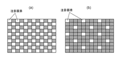
乳剤傷判定処理を受けない画素を飛ばして注目画素を指定する注目画素飛ばし指定による乳剤傷判定処理の具体例の1つとして、本発明の好適な実施形態では、注目画素として指定される画素と指定されない画素がマトリックス展開された前記画像データに関して市松模様を形成するように前記注目画素が飛び越し指定され、前記傷領域拡張ステップにおいて前記乳剤傷領域が飛び越された画素の方向に拡張されることが提案される。ここで言う市松模様とは厳密な意味での市松模様パターンではなく、乳剤傷判定処理対象として指定される注目画素同士の間隔が1画素でもよいし、複数画素分であってもよい。つまり、飛び越し指定された注目画素が、二次元マトリックス面において所定間隔をあけて均一に分布していることが重要である。 As one specific example of emulsion scratch determination processing by skipping pixels that are not subjected to emulsion scratch determination processing and designating a target pixel, in a preferred embodiment of the present invention, a pixel designated as a target pixel The target pixel is skipped and specified so as to form a checkered pattern with respect to the image data in which the unspecified pixels are expanded in the matrix, and the emulsion scratch area is expanded in the direction of the skipped pixel in the scratch area expanding step. Is proposed. The checkered pattern referred to here is not a checkered pattern in a strict sense, and the interval between pixels of interest designated as an emulsion scratch determination processing target may be one pixel or a plurality of pixels. In other words, it is important that the pixels of interest designated as interlaced are uniformly distributed at predetermined intervals on the two-dimensional matrix surface.
乳剤傷判定処理を受けない画素を飛ばして注目画素を指定する注目画素飛ばし指定による乳剤傷判定処理の具体例の他の1つとして、マトリックス展開された前記画像データに関して行単位又は列単位の画素飛ばしで前記注目画素が指定され、前記傷領域拡張ステップにおいて前記乳剤傷領域が画素飛ばしされた行又は列の方向に拡張されることも提案される。ここでは、乳剤傷判定処理対象として指定される注目画素が均一に分布するのではなく、行単位又は列単位で指定される。ここでも、飛ばし指定の間隔幅は、1行又は1列であってもよいし、複数行又は複数列であってもよい。 As another specific example of emulsion damage determination processing by skipping pixels that are not subjected to emulsion scratch determination processing and designating a target pixel, pixel-by-row or column-unit pixels for the image data expanded in matrix It is also proposed that the target pixel is designated by skipping, and the emulsion scratch area is expanded in the direction of the row or column where the pixel skip was performed in the scratch area expansion step. Here, the pixels of interest designated as the emulsion damage determination processing target are not uniformly distributed, but are designated in units of rows or columns. Here, the interval width specified for skipping may be one row or one column, or may be a plurality of rows or a plurality of columns.
乳剤傷がどの程度の画素分にわたって延びているかどうかを推定する場合写真フィルムの画像をフィルムスキャナで画像データ化する際の解像度が重要となるので、本発明による好適な実施形態の1つでは、前記注目画素指定ステップにおける画素飛ばしの所定画素間隔は、取得された画像データの解像度に対応して決定される。 One of the preferred embodiments according to the present invention is that when estimating how many pixels the emulsion scratch extends, the resolution at which an image of a photographic film is converted into image data by a film scanner is important. The predetermined pixel interval for skipping pixels in the target pixel specifying step is determined in accordance with the resolution of the acquired image data.
また、本発明は、上述した乳剤傷判定方法をコンピュータに実行させるプログラムやそのプログラムを記録した媒体も権利の対象とするものである。 The present invention also covers a program for causing a computer to execute the above-described emulsion scratch determination method and a medium on which the program is recorded.
本発明では、さらに、上述した乳剤傷判定方法を実施する乳剤傷判定システムも権利の対象としており、そのような乳剤傷判定システムは、写真フィルムに記録されている画像から取得された多数の画素から構成される画像データから順次所定画素間隔で注目画素を飛ばし指定する注目画素指定部と、前記注目画素が乳剤傷候補画素であるかどうかを判定する乳剤傷候補画素判定部と、前記乳剤傷候補画素判定部で判定された乳剤傷候補画素の周辺領域に位置する正常画素を探索する正常画素探索部と、前記正常画素探索部で検出された前記正常画素の画素値に基づいて乳剤傷判定条件を作成する乳剤傷判定条件作成部と、前記乳剤傷判定条件に基づいて前記乳剤傷候補画素が乳剤傷画素かどうかを判定する乳剤傷画素判定部と、前記乳剤傷画素判定部で判定された乳剤傷画素の画素位置を前記写真フィルムの乳剤傷による影響を受けている乳剤傷画素を規定する乳剤傷マップに書き込むマップ記録部と、前記飛ばし指定する際の前記所定画素間隔に対応して、前記乳剤傷マップにおける乳剤傷領域を前記注目画素として指定されなかった画素方向に拡張する傷領域拡張部と、から構成されている。当然ながら、このような乳剤傷判定システムも上述した乳剤傷判定方法で述べたすべての実施態様を備えるとともに、上述した全ての作用効果を得ることができる。
本発明によるその他の特徴及び利点は、以下図面を用いた実施形態の説明により明らかになるだろう。
In the present invention, an emulsion scratch determination system for carrying out the above-described emulsion scratch determination method is also subject to the right, and such an emulsion scratch determination system includes a large number of pixels acquired from an image recorded on a photographic film. A pixel-of-interest specifying unit for sequentially skipping and specifying a pixel of interest at predetermined pixel intervals from the image data, an emulsion scratch candidate pixel determining unit for determining whether the pixel of interest is an emulsion scratch candidate pixel, and the emulsion scratch A normal pixel search unit for searching for a normal pixel located in a peripheral region of the emulsion scratch candidate pixel determined by the candidate pixel determination unit, and an emulsion scratch determination based on the pixel value of the normal pixel detected by the normal pixel search unit An emulsion scratch determination condition creating unit for creating conditions, an emulsion scratch pixel determination unit for determining whether or not the emulsion scratch candidate pixel is an emulsion scratch pixel based on the emulsion scratch determination condition, and the emulsion scratch A map recording unit for writing the emulsion scratch map defining the emulsion scratch pixels that are affected pixel position of emulsion scratch pixels determined by the element determination unit by emulsion scratch of the photographic film, the predetermined time of the skip designated Corresponding to the pixel interval, it is composed of a flaw area extending portion for extending the emulsion flaw area in the emulsion flaw map in the pixel direction not designated as the target pixel . Naturally, such an emulsion scratch determination system also includes all the embodiments described in the above-described emulsion scratch determination method, and can obtain all the above-described effects.
Other features and advantages of the present invention will become apparent from the following description of embodiments using the drawings.
本発明の実施の形態について、図面に基づいて説明する。
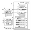
図1は本発明による乳剤傷判定技術を採用したフィルム傷修正処理ユニットを搭載した写真プリント装置を示す外観図であり、この写真プリント装置は、ここでは図示されていないフィルム現像機によって現像処理された写真フィルム1(以下、単にフィルムと略称する)の撮影画像コマを多数の画素からなるデジタル画像データ(以下、単に画像データと略称する)として読み取るフィルムスキャナ3や取得された画像データに画像処理を施してプリント情報を作成するコントローラ5などを備えた操作ステーションOSと、操作ステーションOSからのプリント情報に基づいて印画紙2に対して露光処理と現像処理とを行って写真プリント2aを作成するプリントステーションPSとから構成されている。コントローラ5は、基本的には汎用パソコンから構成されており、本発明による乳剤傷判定技術を組み込んだフィルム傷修正処理ユニットを実装している。このパソコンには、この写真プリント装置の操作画面を表示するモニタ4a、デジタルカメラ等で利用されているメモリカード等から画像データを読み込むメディアリーダ4b、オペレータによる操作入力に用いられるキーボード4c等が組み込まれている。
Embodiments of the present invention will be described with reference to the drawings.
FIG. 1 is an external view showing a photographic printing apparatus equipped with a film flaw correction processing unit employing an emulsion flaw determination technique according to the present invention. This photographic printing apparatus is developed by a film developing machine not shown here. In addition, a
プリントステーションPSは、図2に示されているように、2つの印画紙マガジン11に納めたロール状の印画紙2を引き出してシートカッター12でプリントサイズに切断すると共に、このように切断された印画紙2に対し、バックプリント部13で色補正情報やコマ番号などのプリント処理情報を印画紙2の裏面に印字するとともに、露光プリント部14で印画紙2の表面に撮影画像の露光を行い、この露光後の印画紙2を複数の現像処理槽を有した処理槽ユニット15に送り込んで現像処理する。乾燥の後に装置上部の横送りコンベア16からソータ17に送られた印画紙2、つまり写真プリント2aは、このソータ17の複数のトレイ17aにオーダ単位で仕分けられた状態で集積される(図1参照)。
As shown in FIG. 2, the print station PS draws out the roll-shaped
上述した印画紙2に対する各種処理に合わせた搬送速度で印画紙2を搬送するために印画紙搬送機構18が敷設されている。印画紙搬送機構18は、印画紙搬送方向に関して露光部14の前後に配置されたチャッカー式印画紙搬送ユニット18aを含む複数の挟持搬送ローラ対から構成されている。
A photographic
露光プリント部14には、副走査方向に搬送される印画紙2に対して、主走査方向に沿って操作ステーションOSからのプリントデータなどのプリント情報に基づいてR(赤)、G(緑)、B(青)の3原色のレーザ光線の照射を行うライン露光ヘッドが設けられている。処理槽ユニット15は、発色現像処理液を貯留する発色現像槽15aと、漂白定着処理液を貯留する漂白定着槽15bと、安定処理液を貯留する安定槽15cを備えている。
The
フィルムスキャナ3はフィルム傷修正のための構成部材を備えたフィルムスキャナであり、主な構成要素として、照明光学系31、撮像光学系としてのズームレンズ32、入射してきた光を可視光と赤外光に分けるダイクロイックミラー33、可視光用センサユニット34、赤外光用センサユニット35を備えている。照明光学系31は、光源としてのハロゲンランプ又は発光ダイオードと、その光源からの光を調光するミラートンネルや拡散板などから構成されている。可視光用センサユニット34は、フィルム1の3つの基本色成分(例えばR:赤色成分、G:緑色成分、B:青色成分)からなる可視光画像を検出するためにそれぞれ適合するカラーフィルタを装着した3つのCCDアレイ34aと、これらのCCDアレイ34aによって検出された可視光信号を処理して基本色成分で構成されたR・G・B画像データを生成してコントローラ5へ転送する可視光用信号処理回路34bを備えている。これに対して、赤外光用センサユニット35は、フィルム1に付いている傷の状態を赤外光画像として検出するためにダイクロイックミラー33から分岐された赤外光のみを受けるように配置されたCCDアレイ35aと、このCCDアレイ35aによって検出された赤外光信号を処理して赤外光画像データを生成してコントローラ5へ転送する赤外光用信号処理回路35bを備えている。
The
このように構成されたフィルムスキャナ3では、フィルム1の撮影画像コマが所定の読取位置に位置決めされると、撮影画像コマの読取処理が開始されるが、その際撮影画像コマの投影光像は、フィルム搬送機構36によるフィルム1の副走査方向への送り操作により、複数のスリット画像に分割された形で順次可視光用センサユニット34及び赤外光用センサユニット35によって読み取られ、R、G、Bの色成分の画像信号並びに赤外成分の画像信号に光電変換され、生の画像データとしてコントローラ5に送られる。このような、照明光学系31、撮像光学系32、可視光用センサユニット34及び赤外光用センサユニット35の各制御はコントローラ5からの動作指令によって行われている。
In the
コントローラ5は、CPUを中核部材として、入力されたデータに対して種々の処理を行うための機能部がハードウエア又はソフトウエア或いはその両方で構築されているが、本発明に特に関係する機能部として、図3に示されているように、可視光用センサユニット34によって取得された可視光画像データ及び赤外光用センサユニット35によって取得された赤外光画像データを用いて後で詳しく説明するフィルム1の傷に起因する欠陥画素(傷画素)の修正を行うフィルム傷修正処理ユニット6、フィルム傷修正されメモリ51に展開されている画像データに対して色調補正やフィルタリング(ぼかしやシャープネスなど)やトリミングなどの各種画像処理を施す画像処理部52、画像データやその他の表示アイテムをビデオメモリに取り込むとともにこのビデオメモリに展開されたイメージをビデオコントローラによってビデオ信号に変換してモニタ4aに送るビデオ制御部53、画像処理部52で処理された最終的な画像データ等をプリントデータに変換してプリントステーションPSの露光プリント部14に転送するプリントデータ生成部54、GUIを用いて作り出された操作画面の下でキーボード4c等を通じて入力された操作指令や予めプログラム化された操作指令に基づいて各機能部を制御するプリント管理部55が挙げられる。
The
フィルム傷修正処理ユニット6は、フィルムスキャナ3から送られてきた可視光画像データおよび赤外光画像データを用いて、ベース傷除去処理、乳剤傷検出処理、乳剤傷除去処理を実行するものであり、前処理モジュール61と、ベース傷除去モジュール62と、乳剤傷判定モジュール63と、乳剤傷除去モジュール64、内部メモリ65を備えている。
The film flaw
前処理モジュール61は、ベース傷除去処理、および乳剤傷検出処理の前段階となる処理を実行するモジュールである。具体的には、前処理モジュール61は、傷による影響を受けていない画素(以下、「正常画素」とする)の赤外光画像データの画素値であるクリアフィルム値(以下CF値と略称する)を算出する。なお、「傷」とは上記ベース傷と乳剤傷との両方を意味することとする。
The
同一フィルム1から得られた赤外光画像データと可視光画像データとでは互いに画素が対応関係にある。一方、フィルム1を透過する赤外光は、フィルム1のベース傷により影響を受けるものの、フィルム1の色素により影響を受けることがない。すなわち、赤外光画像データにはベース傷の情報が含まれるものの、フィルム1に形成されている画像情報が含まれることはなく、ベース傷の影響を受けている画素(以下、「ベース傷画素」とする)は、傷のない状態から画素値が低下する傾向にある。よって、CF値は、正常画素とベース傷画素とを区別するための閾値として用いることができ、赤外光画像データの画素値がCF値以下の画素をベース傷画素と判断することができる。
The infrared light image data and the visible light image data obtained from the
ベース傷除去モジュール62は、上述したベース傷除去処理を実行するモジュールであり、具体的には、ベース傷画素に関して、CF値から赤外光画像データの画素値を引くことにより、該当ベース傷画素における傷のない状態からの画素値低下量を算出すると共に、可視光画像データにおける赤色成分,緑色成分,青色成分の各画素値に、上記画素値低下量を加算する処理を実行する。 The base flaw removal module 62 is a module that executes the above-described base flaw removal processing. Specifically, for the base flaw pixel, the base flaw pixel is obtained by subtracting the pixel value of the infrared light image data from the CF value. The pixel value decrease amount from a state in which there is no flaw is calculated, and a process of adding the pixel value decrease amount to each pixel value of the red component, the green component, and the blue component in the visible light image data is executed.
ベース傷は、フィルム1上のベース面に傷が付されているものの、基本的に色素が欠落しているものではないので、ベース傷画素における傷のない状態からの画素値低下量は、赤色成分,緑色成分,青色成分でほぼ等しいと考えられる。したがって、各ベース傷画素に関して、CF値と赤外光画像データの画素値との差である画素値低下量を、赤色成分,緑色成分,青色成分の各画素値に加算すれば、ベース傷による影響をベース傷画素から除去することができる。
Although the base scratch is scratched on the base surface on the
ところが、乳剤傷は、フィルム1の各色成分の色素が欠落しているものであるから、乳剤傷画素における可視光画像データの画素値は、乳剤傷がない状態から上昇する。さらに、色素の欠落量は、色成分ごとに異なるものとなる。このため、乳剤傷画素における可視光画像データの傷がない状態からの画素値上昇量は、赤色成分,緑色成分,青色成分のそれぞれで異なるものとなる。したがって、乳剤傷による影響を乳剤傷画素から除去するためには、上記ベース傷除去処理とは異なる処理が必要になる。
However, since the emulsion scratches are those in which the color components of the
乳剤傷判定モジュール63は、前処理モジュール61により決定されたCF値を赤外光画像データに適用しながら可視光画像データを処理して、乳剤傷画素を検出し、検出された乳剤傷画素の画素位置を示した乳剤傷マップを作成するモジュールである。なお、乳剤傷判定モジュール63は、図4に示すように、画像データから順次所定画素間隔で注目画素を飛ばし指定する注目画素指定部63aと、指定された注目画素が乳剤傷候補画素であるかどうかを判定する乳剤傷候補画素判定部63bと、乳剤傷候補画素判定部63bで判定された乳剤傷候補画素の周辺領域に位置する正常画素を探索する正常画素探索部63cと、正常画素探索部63cで検出された正常画素の画素値に基づいて乳剤傷判定条件を作成する乳剤傷判定条件作成部63dと、作成された乳剤傷判定条件に基づいて乳剤傷候補画素が乳剤傷画素かどうかを判定する乳剤傷画素判定部63eと、乳剤傷画素判定部63eで判定された乳剤傷画素の画素位置を乳剤傷マップに書き込むマップ記録部63fとから構成されているが、これら各機能要素の処理手順については、後に詳述する。ここで特筆すべきことは、注目画素指定部63aが、乳剤傷判定処理時間の短縮化のために、取得された画像データを構成する全画素が注目画素として指定されるのではなく、予め設定された所定画素間隔をあけながら注目画素を指定することである。注目画素の飛び越し間隔は、取得された画像データの解像度等から推定される、乳剤傷がまたがっている画素数に基づいて設定される。
The emulsion
乳剤傷除去モジュール64は、注目画素指定部63aが設定した画素飛ばし間隔に対応して乳剤傷マップで示されている乳剤傷領域を拡張した後、その乳剤傷マップで規定される乳剤傷画素位置に対応する可視光画像データの色成分ごとの画素値を補間法を用いて修正することで乳剤傷除去処理を実行するモジュールである。
The emulsion
つぎに、フィルム傷修正処理ユニット6における処理の流れについて、図5に示すフローチャートに基づいて説明する。まず、フィルムスキャナ3によって取得されたフィルム1からの画像データ、ここでは可視光画像データ及び赤外光画像データが、フィルム傷修正処理ユニット6に送り込まれる(#01)。フィルム傷修正処理ユニット6に送り込まれた画像データは、前処理モジュール61におけるCF値の決定のために利用される(#02)。
Next, the flow of processing in the film flaw
CF値とは、基本的には正常画素の赤外光画像データの画素値であるが、代表的なCF値算定方法の1つが、前述した特許文献2である特開2004−132743号公報の段落番号0068〜0080に詳しく説明されている。つまり、CF値を求めるに先立って、まず、仮のCF値を算出して、この仮のCF値を閾値として、正常画素と考えうる画素のみを検出し、検出された正常画素と考えうる画素のみを用いて赤色リーケージ算出を行うことで、赤外光画像データから赤色リーケージを除去した補正赤外光画像データを作り出し、そこから真のCF値を求めている。その結果、このCF値は、仮のCF値よりも、正常画素の赤外光画像データの画素値に近い値となる。
The CF value is basically a pixel value of infrared image data of normal pixels, but one typical CF value calculation method is disclosed in Japanese Patent Application Laid-Open No. 2004-132743, which is
次いで、ベース傷除去モジュール62は、前処理モジュール61から受け取った赤外光画像データ(赤色リーケージが除かれた赤外光画像データ)及び可視光画像データと前処理モジュール61で決定されたCF値を用いてベース傷除去処理を行う(#03)。このベース傷除去処理では、赤外光画像データの画素値がCF値より低い画素がベース傷画素と判断されるとともに、各ベース傷画素に関し、
(補正量)=(本CF値)−(赤外光画像データの画素値)
が算出され、各ベース傷画素に関して、可視光画像データにおける各色成分の画素値に上記補正量が加算されることで、ベース傷除去後の可視光画像データが出力されることになる。
Next, the base scratch removal module 62 receives the infrared light image data (the infrared light image data from which the red leakage has been removed) and the visible light image data received from the
(Correction amount) = (main CF value) − (pixel value of infrared light image data)
And the correction amount is added to the pixel value of each color component in the visible light image data for each base scratch pixel, so that the visible light image data after removal of the base scratch is output.
次に、乳剤傷判定モジュール63が、ベース傷除去後の可視光画像データと赤外光画像データ及び前処理モジュール61で決定されたCF値を用いて乳剤傷画素を検出し、乳剤傷マップを作成する処理を行う(#04)。この乳剤傷マップ作成処理はすぐ後で詳しく説明される。乳剤傷マップが作成されると、前述したように、この乳剤傷マップ上の乳剤傷領域を拡張する処理が施され(#05)、乳剤傷領域が拡張された乳剤傷マップを用いて、可視光画像データに含まれている乳剤傷画素を修正する乳剤傷除去処理が実行される(#06)。乳剤傷除去処理は、いわゆる周辺の正常画素の画素値を用いた補間法によって行われ、種々の乳剤傷除去アルゴリズムが知られているが、例えば、特開2001−78038号公報や特開2004−266481号公報が参照される。乳剤傷除去処理を受けた可視光画像データは画像処理部52に適当な画像処理を施された後、写真プリント作製のためのプリントデータに変換される。
Next, the emulsion
前述した乳剤傷マップ作成処理を図6と図7に示されたフローチャートを用いて詳しく説明する。なお、この乳剤傷マップ作成処理においてもCF値が用いられるが、ここで用いられるCF値はベース傷除去処理で用いられたCF値よりわずかに高くしておくことが好ましい。これは、乳剤傷画素における赤外光画像データの画素値が、ベース傷画素における赤外光画像データの画素値よりも若干高い傾向にあることが経験的に認められているからである。 The emulsion scratch map creation process described above will be described in detail with reference to the flowcharts shown in FIGS. Note that the CF value is also used in this emulsion scratch map creation process, but the CF value used here is preferably slightly higher than the CF value used in the base scratch removal process. This is because it has been empirically recognized that the pixel value of the infrared light image data in the emulsion scratch pixel tends to be slightly higher than the pixel value of the infrared light image data in the base scratch pixel.
まず、注目画素指定部63aによる注目画素の指定である(#40)。本発明による乳剤傷判定モジュール63では、送り込まれてきた画像データを構成する全画素を順次注目画素として指定されるのではなく、予め設定された所定画素間隔分だけ飛び越しながら注目画素を指定する。図8にこの注目画素の飛び越し指定の1つのパターンが模式的に示されている。図8において、白地のマス目が乳剤傷判定処理対象として注目画素に指定される画素であり、黒地のマス目が乳剤傷判定処理非対象として注目画素に指定されない画素である。図8(a)のパターンは1画素飛ばしの市松模様となっているが、図8(b)のパターンは2画素飛ばしの市松模様となっている。このような異なる画素飛ばしパターンからの選択は、取得した画像データの解像度や推定される乳剤傷の大きさ等から決定され、一般的な解像度の場合図8(a)のパターンが選択され、極めて高い解像度の場合図8(b)のパターンないしはさらに3以上の画素を飛ばすパターンが採用される。
First, the target pixel is specified by the target
もちろん、注目画素の飛び越し指定の1つのパターンは図8に示されたような市松模様だけに限定されるわけではなく、例えば図9に示すようなパターン、つまりマトリックス展開された画像データに関して行単位又は列単位の画素飛ばしで注目画素が指定されるパターンなども適用できる。さらには、図8や図9に示されたパターン、あるいは必要に応じてさらに別なパターンも用意しておき、これらの異なる複数のパターンから選択されたパターンを用いて画素飛ばしを行うような構成を採用してもよい。 Of course, one pattern for specifying the skipping of the target pixel is not limited to the checkered pattern as shown in FIG. 8, for example, as shown in FIG. Alternatively, a pattern in which a pixel of interest is designated by skipping pixels in units of columns can be applied. Furthermore, the pattern shown in FIG. 8 or FIG. 9, or another pattern as required, is prepared, and a pixel skip is performed using a pattern selected from a plurality of these different patterns. May be adopted.
なお、注目画素指定部63aにおいて、例えば、図8(a)のパターンに基づく注目画素指定が採用された場合、乳剤傷マップ上の乳剤傷領域を拡張する処理(ステップ#5)においては、乳剤傷領域が上下左右の4方向に1画素分拡張され、また、注目画素指定部63aにおいて、例えば、図9(a)のパターンに基づく注目画素指定が採用された場合、乳剤傷マップ上の乳剤傷領域を拡張する処理(ステップ#5)においては、乳剤傷領域が左右の2方向に1画素分拡張されるとよい。
Note that, in the pixel-of-
注目画素が指定されると、その赤外光画素値:WdとCF値が比較され(#41)、赤外光画素値:WdがCF値より低い場合その注目画素は乳剤傷候補とみなされ次のステップに移行する。赤外光画素値:WdがCF値以上の場合その注目画素は乳剤傷候補とみなされず、次の注目画素が存在する場合ステップ#40に戻って次の注目画素の指定が行われる。乳剤傷候補とみなされた画素に対しては、可視光画像データの対応する画素から、
各色の平均値:Wave=(Wr+Wg+Wb)/3
を求めておく(#42)。なお、Wrは注目画素の赤色成分画素値、Wgは注目画素の緑色成分画素値、Wbは注目画素の青色成分画素値である。
When the pixel of interest is designated, its infrared light pixel value: Wd is compared with the CF value (# 41). If the infrared light pixel value: Wd is lower than the CF value, the pixel of interest is regarded as an emulsion scratch candidate. Move on to the next step. When the infrared pixel value: Wd is greater than or equal to the CF value, the target pixel is not regarded as an emulsion scratch candidate, and when there is a next target pixel, the process returns to step # 40 to designate the next target pixel. For pixels considered as emulsion scratch candidates, from the corresponding pixels in the visible light image data,
Average value of each color: Wave = (Wr + Wg + Wb) / 3
(# 42). Wr is the red component pixel value of the target pixel, Wg is the green component pixel value of the target pixel, and Wb is the blue component pixel value of the target pixel.
乳剤傷候補とみなされた注目画素に関しては、この乳剤傷候補が実際に乳剤傷と判定されるかどうかの判定条件を設定するために必要となる注目画素周辺領域での正常画素の探索が行われる(#43)。この周辺領域での正常画素探索処理を図7のフローチャートと図10の探索順序模式図を用いて説明する。正常画素の探索は探索領域として注目画素(図10で黒く塗りつぶされた画素)を中心画素としてその第1外周画素群(3×3マトリックスの外周画素)から順次外周画素群を拡張していきながら行うものであり、ここでは最終外周画素群を第3外周画素群(7×7マトリックスの外周画素としているがこれは任意に設定可能である。なお、指定された外周画素が正常画素であると判定される条件は、指定外周画素の赤外光画素値がCF値より大きいことである。 With respect to a target pixel regarded as an emulsion scratch candidate, a normal pixel search is performed in the region surrounding the target pixel, which is necessary to set a determination condition for determining whether or not this emulsion scratch candidate is actually determined as an emulsion scratch. (# 43). The normal pixel search process in this peripheral area will be described with reference to the flowchart of FIG. 7 and the search order schematic diagram of FIG. The normal pixel search is performed by expanding the outer peripheral pixel group sequentially from the first outer peripheral pixel group (the outer peripheral pixel of the 3 × 3 matrix) with the target pixel (the pixel painted black in FIG. 10) as the central pixel as a search area. Here, the final outer peripheral pixel group is the third outer peripheral pixel group (the outer peripheral pixel of the 7 × 7 matrix, but this can be arbitrarily set. Note that the designated outer peripheral pixel is a normal pixel. The condition to be determined is that the infrared light pixel value of the designated outer peripheral pixel is larger than the CF value.
まず、探索領域として第1外周画素群が設定されるが、これは注目画素を中心とする3×3マトリックスの8つの外周画素である。実際のプログラムでは、直接二次元マトリックスの要素位置を指定するといった方式が用いられるが、ここでは処理の説明を簡単にするため、図10に示すように、第1外周画素群に属する各画素に1〜8の指標:mを付与しておくことにする。従って、例えばm=1は左上端の画素を特定することになる。初期設定としてm=0、Max=8(特定外周画素群の画素に割り当てられたmの最大値)が設定される(#430)。続いて、外周画素群に対する探索ルーチンをはじめるためmの値をインクリメントし(#431)、mによって特定される外周画素の赤外光画素値:Wd(m)がCF値と比較される(#432)。外周画素の赤外光画素値がCF値以下の場合(#432No分岐)この外周画素は正常画素とは判定されず、次の外周画素の判定を行う。外周画素の赤外光画素値がCF値より大きい場合(#432Yes分岐)この外周画素は正常画素と判定され、後のステップで行われる各正常画素の平均値算出のために以下の各画素値累計処理が行われる、
赤色成分累計:Sr=Sr+Wr(m)
緑色成分累計:Sg=Sg+Wg(m)
青色成分累計:Sb=Sb+Wb(m)
赤外成分累計:Sd=Sd+Wd(m)
、ここでWr(m)はmによって特定された外周画素の赤色成分画素値、Wg(m)はmによって特定された外周画素の緑色成分画素値、Wb(m)はmによって特定された外周画素の青色成分画素値である(#433)。
さらに、正常画素が正常画素累計:CNTに計数される(#434)。次いで、mの値が最大値:Maxに達しているかどうか、つまり第1外周画素群に含まれる全ての画素が判定されたかどうかチェックされ(#435)、未判定の画素が残っていると(#435No分岐)ステップ#431にジャンプして次の画素の判定を行う。第1外周画素群に含まれる全ての画素の判定が終了している場合(#435Yes分岐)、正常画素累計:CNTが前もって設定されている判定値(例えば10)以上であるかどうかチェックされ(#436)、判定値以上の場合(#436Yes分岐)この正常画素探索ルーチンを終了して、先のルーチンに戻る。正常画素累計:CNTが判定値に達していない場合(#436No分岐)、探索領域として最終外周画素群(ここでは第3外周画素群)までカバーされたがどうかチェックされ(#437)、最終外周画素群が探索されている場合は(#437Yes分岐)この正常画素探索ルーチンを終了して、先のルーチンに戻る。さらに探索すべき外周画素群が残っている場合(#437No分岐)、次の外周画素群のための設定を行って(#438)、ステップ#431にジャンプして次の外周画素群を探索領域とする正常画素探索をスタートする。
First, a first outer peripheral pixel group is set as a search area, and this is eight outer peripheral pixels of a 3 × 3 matrix centering on the target pixel. In the actual program, a method of directly specifying the element position of the two-dimensional matrix is used, but here, in order to simplify the explanation of the processing, as shown in FIG. 10, each pixel belonging to the first outer peripheral pixel group is assigned to each pixel. An index of 1 to 8: m is given. Therefore, for example, m = 1 specifies the upper left pixel. As an initial setting, m = 0 and Max = 8 (the maximum value of m assigned to the pixels of the specific outer peripheral pixel group) are set (# 430). Subsequently, in order to start a search routine for the outer peripheral pixel group, the value of m is incremented (# 431), and the infrared light pixel value Wd (m) of the outer peripheral pixel specified by m is compared with the CF value (#). 432). When the infrared pixel value of the outer peripheral pixel is equal to or less than the CF value (# 432 No branch), this outer peripheral pixel is not determined as a normal pixel, and the next outer peripheral pixel is determined. When the infrared pixel value of the outer peripheral pixel is larger than the CF value (# 432 Yes branch), this outer peripheral pixel is determined as a normal pixel, and the following pixel values are calculated for calculating the average value of each normal pixel performed in a later step. Cumulative processing is performed,
Red component total: Sr = Sr + Wr (m)
Green component total: Sg = Sg + Wg (m)
Blue component cumulative: Sb = Sb + Wb (m)
Infrared component accumulation: Sd = Sd + Wd (m)
Where Wr (m) is the red component pixel value of the outer peripheral pixel specified by m, Wg (m) is the green component pixel value of the outer peripheral pixel specified by m, and Wb (m) is the outer periphery specified by m. This is the blue component pixel value of the pixel (# 433).
Further, the normal pixels are counted in the normal pixel accumulation: CNT (# 434). Next, it is checked whether or not the value of m has reached the maximum value: Max, that is, whether or not all the pixels included in the first outer peripheral pixel group have been determined (# 435), and if undetermined pixels remain ( (# 435 No branch) Jump to step # 431 to determine the next pixel. When the determination of all the pixels included in the first outer peripheral pixel group has been completed (# 435 Yes branch), it is checked whether the normal pixel accumulation: CNT is equal to or greater than a predetermined determination value (for example, 10) ( If it is equal to or greater than the determination value (# 436 Yes branch), the normal pixel search routine is terminated and the process returns to the previous routine. Normal pixel accumulation: When the CNT has not reached the judgment value (# 436 No branch), it is checked whether or not the search area is covered up to the final outer peripheral pixel group (here, the third outer peripheral pixel group) (# 437). If the pixel group is searched (# 437 Yes branch), the normal pixel search routine is terminated and the process returns to the previous routine. Further, if there are remaining outer pixel groups to be searched (# 437 No branch), settings are made for the next outer pixel group (# 438), and the process jumps to step # 431 to search for the next outer pixel group. The normal pixel search is started.
図7で示した正常画素探索ルーチンから戻ると、乳剤傷マップ作成処理では、正常画素累計:CNTが1以上であるかどうかチェックされる(#44)。正常画素累計:CNTが1以上であれば乳剤傷判定条件作成処理に入る(#48)。正常画素累計:CNTが0であれば、正常画素判定の条件つまりCF値を緩めて再度正常画素探索を行うため、これまでに乳剤傷候補画素から本当の乳剤傷画素と判定された最新の画素(前回の乳剤傷画素)の各色平均値に微少値を加えた値を新らたなCF値とし(#45)、図7で示された正常画素探索ルーチンを呼び出して、再度正常画素探索を行う(#46)。この正常画素判定の条件を緩めておこなった正常画素探索においても正常画素が見つからなかった場合(#47No分岐)この乳剤傷候補画素は正常画素と判断し、次の注目画素に移行する。正常画素判定の条件を緩めておこなった正常画素探索において正常画素が見つかった場合(#47Yes分岐又は#436Yes分岐)、乳剤傷判定条件作成処理に入る(#48)。 Returning from the normal pixel search routine shown in FIG. 7, in the emulsion scratch map creation process, it is checked whether or not the normal pixel total: CNT is 1 or more (# 44). Normal pixel accumulation: If CNT is 1 or more, the emulsion defect determination condition creation process is started (# 48). Normal pixel accumulation: If CNT is 0, the normal pixel determination condition, that is, the CF value is relaxed and normal pixel search is performed again. Therefore, the latest pixel that has been determined to be a real emulsion scratch pixel from the emulsion scratch candidate pixels so far A value obtained by adding a small value to the average value of each color of (previous emulsion scratched pixels) is set as a new CF value (# 45), and the normal pixel search routine shown in FIG. (# 46). If a normal pixel is not found in the normal pixel search performed by relaxing the normal pixel determination conditions (No branch at # 47), the emulsion scratch candidate pixel is determined to be a normal pixel, and the process proceeds to the next target pixel. If normal pixels are found in the normal pixel search performed by relaxing the normal pixel determination conditions (# 47 Yes branch or # 436 Yes branch), the processing enters emulsion scratch determination condition creation processing (# 48).
この乳剤傷判定条件作成処理では、まず、各色成分累計Sr、Sg、Sbと赤外成分累計Sdと正常画素累計:CNTから以下の演算値を求める、
赤平均:ave_r=Sr/CNT、
緑平均:ave_g=Sr/CNT、
青平均:ave_b=Sr/CNT、
赤外平均:ave_d=Sr/CNT、
画素平均:LA=(ave_r+ave_g+ave_b)/3。
乳剤傷判定条件は3つ用意され、
(1)判定条件1は、「Wave>LA+upper」又は「Wave<LA+lower」であり、upperとlowerは定数である。
(2)判定条件2は、「Wb−ave_b>Wg−ave_g」かつ「Wb−ave_b>Wr−ave_r+rto」であり、rtoは定数である。Wr、Wg、Wbは注目画素の各色画素値。
(3)判定条件3は、「Wd<ave_d+depth」であり、depthは定数である。
In this emulsion scratch determination condition creation process, first, the following calculated values are obtained from each color component total Sr, Sg, Sb, infrared component total Sd, and normal pixel total: CNT.
Red average: ave_r = Sr / CNT,
Green average: ave_g = Sr / CNT,
Blue average: ave_b = Sr / CNT,
Infrared average: ave_d = Sr / CNT,
Pixel average: LA = (ave_r + ave_g + ave_b) / 3.
There are three conditions for judging emulsion scratches.
(1) The
(2) The
(3) The
乳剤傷判定条件作成が作成されると、乳剤傷候補とみなされた注目画素が本当の乳剤傷であるかどうか判定される(#49)。この判定処理では、まず判定条件1を満たさない注目画素は正常画素と断定される。判定条件1を満たす場合、さらに処理対象フィルムがネガであるかポジであるかに区分けされる。ネガフィルムの場合では、〔判定条件1かつ(判定条件2又は判定条件3)〕という組み合わせ判定条件を満たしているならば、その注目画素は乳剤傷画素とみなされ。ポジフィルムの場合では、〔判定条件1かつ(判定条件2かつ判定条件3)〕という組み合わせ判定条件を満たしているならば、その注目画素は乳剤傷画素とみなされる。いずれにせよ、注目画素が乳剤傷画素とみなされた場合のみ(#49Yes分岐)、この注目画素の位置が乳剤傷マップに記録される(#49)。上述したステップ#40〜#50までの乳剤傷マップ作成処理が指定すべき注目画素がなくなるまで繰り返し実行される(#51)。
When the emulsion scratch determination condition creation is created, it is determined whether or not the target pixel regarded as an emulsion scratch candidate is a real emulsion scratch (# 49). In this determination process, first, a target pixel that does not satisfy the
なお、上述した乳剤傷判定条件作成及びその乳剤傷判定条件を用いた乳剤傷判定処理に関しては、前述した特許文献2である特開2004−132743号公報の段落番号0085〜0135に詳しく説明されているので、参照することができる。 The preparation of the emulsion scratch determination conditions and the emulsion scratch determination processing using the emulsion scratch determination conditions are described in detail in paragraph Nos. 0085 to 0135 of Japanese Patent Application Laid-Open No. 2004-132743, which is described above. You can refer to it.
以上述べたように、本発明では、フィルム傷修正処理ユニット6において実行されるフィルム傷修正の処理速度を高めるために、特に処理負担の大きな乳剤傷マップ作成時に注目画素の飛び越し指定を行うとともに作成された乳剤傷マップ上の乳剤傷領域を拡張することが提案されているが、さらに処理負担を減少させるために、以下のような方策も提案される。上述したフィルム傷修正処理ユニット6は、DSPボードによって実現されるが、さらなる改善を施したフィルム傷修正処理ユニット6をハードウエアの観点から模式的に示した説明図が図11に示されている。ここでは、前述した前処理モジュール61とベース傷除去モジュール62の機能を有するベース傷処理演算チップ60aとして示されており、さらに平均化処理を行うフィルタ処理演算チップ60b、乳剤傷判定演算チップ60c、乳剤傷補正演算チップ60dが示されている。各演算チップは画像データが転送されるデータラインによって接続されているとともに、フィルタ処理演算チップ60bと乳剤傷判定演算チップ60cとの間には画像データ縮小部60xを介装したサブデータラインが備えられており、乳剤傷判定演算チップ60cと乳剤傷補正演算チップ60dとの間には乳剤傷マップ60yを介装したサブデータラインが備えられている。スキャナ3によって取得された画像データは、ベース傷処理演算チップ60a、フィルタ処理演算チップ60b、乳剤傷判定演算チップ60c、乳剤傷補正演算チップ60dの順に伝送され、最終的にメモリ51に格納される。
As described above, in the present invention, in order to increase the processing speed of the film flaw correction executed in the film flaw
画像データ縮小部60xは、フィルタ処理演算チップ60bから出力される画像データを加算平均することにより、例えば5430×26ピクセルのデータを2670×13ピクセルに縮小する機能を有し、この縮小された画像データを乳剤傷判定演算チップ60cに転送する。乳剤傷判定演算チップ60cは実際の画像データに較べ1/4に縮小された画像データを処理することになるので、その処理が内部メモリ上で可能となり、乳剤傷判定処理の高速化が果たされる。
The image
また、乳剤傷判定演算チップ60cにおける乳剤傷判定処理は、(1)注目画素が閾値(CF値)より下であるかどうかの前判定処理、(2)注目画素が閾値(CF値)より下であればその外周領域を探索して閾値を超える正常画素を見つけ出す探索処理、(3)検出された正常画素の画素値から注目画素が乳剤傷であるかどうかを判定する本判定処理に分けることができるが、前判定処理と探索処理を同時的に実行せずに別々に、つまり乳剤傷判定演算チップ60cへの画像データの入力時に前判定処理だけを行い、その都度の前判定結果は1ビットデータとして内部メモリに保存しておくことができ、さらにこの前判定結果に基づいて探索処理を行うようにすると、前判定処理と探索処理は内部メモリ上で可能となり、前判定結果を外部メモリにはき出して処理することに較べ、その処理速度は高速となる。
The emulsion scratch determination processing in the emulsion scratch
上記実施形態の説明ではカラータイプのフィルムスキャナを例示したが、モノクロタイプのフィルムスキャナにも本発明は適用可能であり、さらにフィルム傷検出のために赤外光以外の非可視光を用いることも可能である。 In the description of the above embodiment, a color type film scanner has been exemplified. However, the present invention can also be applied to a monochrome type film scanner, and invisible light other than infrared light may be used for film scratch detection. Is possible.
本発明は、フィルムスキャナによって取得された画像データからフィルム傷の影響を除去する傷消し技術に適用することができる。 The present invention can be applied to a scratch-removing technique for removing the influence of film scratches from image data acquired by a film scanner.
3:フィルムスキャナ
6:フィルム傷修正処理ユニット
34:可視光用センサユニット
35:赤外光用センサユニット
61:前処理モジュール
62:ベース傷除去モジュール
63:乳剤傷判定モジュール
63a:注目画素指定部
63b:乳剤傷候補画素判定部
63c:正常画素探索部
63d:乳剤傷判定条件作成部
63e:乳剤傷画素判定部
63f:マップ記録部
64:乳剤傷除去モジュール
3: Film scanner 6: Film flaw correction processing unit 34: Visible light sensor unit 35: Infrared light sensor unit 61: Pre-processing module 62: Base flaw removal module 63: Emulsion
Claims (6)
前記画像データから順次所定画素間隔で注目画素を飛ばし指定する注目画素指定ステップと、
前記注目画素が乳剤傷候補画素であるかどうかを判定する乳剤傷候補画素判定ステップと、
前記乳剤傷候補画素判定ステップで判定された乳剤傷候補画素の周辺領域に位置する正常画素を探索する正常画素探索ステップと、
前記正常画素探索ステップで検出された前記正常画素の画素値に基づいて乳剤傷判定条件を作成する乳剤傷判定条件作成ステップと、
前記乳剤傷判定条件に基づいて前記乳剤傷候補画素が乳剤傷画素かどうかを判定する乳剤傷画素判定ステップと、
前記乳剤傷画素判定ステップで判定された乳剤傷画素の画素位置を乳剤傷マップに書き込むマップ記録ステップと、
前記飛ばし指定する際の前記所定画素間隔に対応して、前記乳剤傷マップにおける乳剤傷領域を前記注目画素として指定されなかった画素方向に拡張する傷領域拡張ステップと、からなる乳剤傷判定方法。 An emulsion that creates an emulsion scratch map that defines emulsion scratches that are affected by emulsion scratches in the photographic film based on image data composed of a large number of pixels acquired from an image recorded on the photographic film. In the wound determination method,
A pixel-of-interest specifying step of sequentially skipping and specifying a pixel of interest at a predetermined pixel interval from the image data;
An emulsion scratch candidate pixel determining step for determining whether the pixel of interest is an emulsion scratch candidate pixel;
A normal pixel search step for searching for a normal pixel located in a peripheral region of the emulsion scratch candidate pixel determined in the emulsion scratch candidate pixel determination step;
An emulsion scratch determination condition creating step for creating an emulsion scratch determination condition based on the pixel value of the normal pixel detected in the normal pixel search step;
An emulsion scratch pixel determination step for determining whether the emulsion scratch candidate pixel is an emulsion scratch pixel based on the emulsion scratch determination condition;
A map recording step for writing the pixel position of the emulsion scratch pixel determined in the emulsion scratch pixel determination step in an emulsion scratch map;
A method for determining an emulsion flaw, comprising: a flaw area extending step for extending an emulsion flaw area in the emulsion flaw map in a pixel direction that has not been designated as the pixel of interest in correspondence with the predetermined pixel interval when the skipping is designated .
前記画像データから順次所定画素間隔で注目画素を飛ばし指定する機能と、
前記注目画素が乳剤傷候補画素であるかどうかを判定する機能と、
判定された乳剤傷候補画素の周辺領域に位置する正常画素を探索する機能と、
検出された正常画素の画素値に基づいて乳剤傷判定条件を作成する機能と、
前記乳剤傷判定条件に基づいて前記乳剤傷候補画素が乳剤傷画素かどうかを判定する機能と、
判定された乳剤傷画素の画素位置を乳剤傷マップに書き込む機能と、
前記飛ばし指定する際の前記所定画素間隔に対応して、前記乳剤傷マップにおける乳剤傷領域を前記注目画素として指定されなかった画素方向に拡張する傷領域拡張する機能と、をコンピュータに実行させる乳剤傷判定プログラム。 To create an emulsion scratch map that defines emulsion scratch pixels that are affected by emulsion scratches in the photographic film based on image data composed of a large number of pixels acquired from an image recorded on the photographic film. In addition,
A function of skipping and specifying a pixel of interest at a predetermined pixel interval sequentially from the image data;
A function of determining whether the target pixel is an emulsion scratch candidate pixel;
A function to search for normal pixels located in the peripheral area of the determined emulsion scratch candidate pixels;
A function for creating an emulsion scratch determination condition based on the detected pixel value of a normal pixel,
A function of determining whether the emulsion scratch candidate pixel is an emulsion scratch pixel based on the emulsion scratch determination condition;
A function of writing the determined pixel position of the emulsion scratch pixel to the emulsion scratch map;
An emulsion that causes a computer to execute a function of expanding a scratch area in a direction of a pixel that is not designated as the target pixel in the emulsion scratch map in correspondence with the predetermined pixel interval when the skip is specified. Scratch determination program.
前記画像データから順次所定画素間隔で注目画素を飛ばし指定する注目画素指定部と、
前記注目画素が乳剤傷候補画素であるかどうかを判定する乳剤傷候補画素判定部と、
前記乳剤傷候補画素判定部で判定された乳剤傷候補画素の周辺領域に位置する正常画素を探索する正常画素探索部と、
前記正常画素探索部で検出された前記正常画素の画素値に基づいて乳剤傷判定条件を作成する乳剤傷判定条件作成部と、
前記乳剤傷判定条件に基づいて前記乳剤傷候補画素が乳剤傷画素かどうかを判定する乳剤傷画素判定部と、
前記乳剤傷画素判定部で判定された乳剤傷画素の画素位置を乳剤傷マップに書き込むマップ記録部と、
前記飛ばし指定する際の前記所定画素間隔に対応して、前記乳剤傷マップにおける乳剤傷領域を前記注目画素として指定されなかった画素方向に拡張する傷領域拡張部と、からなる乳剤傷判定システム。 An emulsion that creates an emulsion scratch map that defines emulsion scratches that are affected by emulsion scratches in the photographic film based on image data composed of a large number of pixels acquired from an image recorded on the photographic film. In the wound determination system,
A pixel-of-interest specifying unit for sequentially skipping and specifying a pixel of interest at a predetermined pixel interval from the image data;
An emulsion scratch candidate pixel determining unit that determines whether the pixel of interest is an emulsion scratch candidate pixel;
A normal pixel search unit for searching for a normal pixel located in a peripheral region of the emulsion scratch candidate pixel determined by the emulsion scratch candidate pixel determination unit;
An emulsion scratch determination condition creating unit for creating an emulsion scratch determination condition based on the pixel value of the normal pixel detected by the normal pixel search unit;
An emulsion scratch pixel determination unit for determining whether the emulsion scratch candidate pixel is an emulsion scratch pixel based on the emulsion scratch determination condition;
A map recording unit that writes the pixel position of the emulsion scratch pixel determined by the emulsion scratch pixel determination unit in an emulsion scratch map;
An emulsion flaw determination system comprising: a flaw area expanding unit that expands an emulsion flaw area in the emulsion flaw map in a pixel direction that is not designated as the target pixel in correspondence with the predetermined pixel interval when the skip is designated .
Priority Applications (1)
| Application Number | Priority Date | Filing Date | Title |
|---|---|---|---|
| JP2004331793A JP4560720B2 (en) | 2004-11-16 | 2004-11-16 | Emulsion scratch determination method and emulsion scratch determination system |
Applications Claiming Priority (1)
| Application Number | Priority Date | Filing Date | Title |
|---|---|---|---|
| JP2004331793A JP4560720B2 (en) | 2004-11-16 | 2004-11-16 | Emulsion scratch determination method and emulsion scratch determination system |
Publications (2)
| Publication Number | Publication Date |
|---|---|
| JP2006145226A JP2006145226A (en) | 2006-06-08 |
| JP4560720B2 true JP4560720B2 (en) | 2010-10-13 |
Family
ID=36625109
Family Applications (1)
| Application Number | Title | Priority Date | Filing Date |
|---|---|---|---|
| JP2004331793A Expired - Fee Related JP4560720B2 (en) | 2004-11-16 | 2004-11-16 | Emulsion scratch determination method and emulsion scratch determination system |
Country Status (1)
| Country | Link |
|---|---|
| JP (1) | JP4560720B2 (en) |
Citations (3)
| Publication number | Priority date | Publication date | Assignee | Title |
|---|---|---|---|---|
| JP2000161948A (en) * | 1998-11-30 | 2000-06-16 | Hitachi Ltd | Apparatus and method for inspecting circuit pattern |
| JP2004038885A (en) * | 2002-07-08 | 2004-02-05 | Adoin Kenkyusho:Kk | Image feature learning type defect detection method, defect detection device and defect detection program |
| JP2004132743A (en) * | 2002-10-08 | 2004-04-30 | Noritsu Koki Co Ltd | Emulsion scratch determination method, device, and program, and recording medium stored with emulsion scratch determination program |
-
2004
- 2004-11-16 JP JP2004331793A patent/JP4560720B2/en not_active Expired - Fee Related
Patent Citations (3)
| Publication number | Priority date | Publication date | Assignee | Title |
|---|---|---|---|---|
| JP2000161948A (en) * | 1998-11-30 | 2000-06-16 | Hitachi Ltd | Apparatus and method for inspecting circuit pattern |
| JP2004038885A (en) * | 2002-07-08 | 2004-02-05 | Adoin Kenkyusho:Kk | Image feature learning type defect detection method, defect detection device and defect detection program |
| JP2004132743A (en) * | 2002-10-08 | 2004-04-30 | Noritsu Koki Co Ltd | Emulsion scratch determination method, device, and program, and recording medium stored with emulsion scratch determination program |
Also Published As
| Publication number | Publication date |
|---|---|
| JP2006145226A (en) | 2006-06-08 |
Similar Documents
| Publication | Publication Date | Title |
|---|---|---|
| JP4244018B2 (en) | Defective pixel correction method, program, and defective pixel correction system for implementing the method | |
| JP3952301B2 (en) | Image processing apparatus, method, and program | |
| JP4431949B2 (en) | Red-eye correction method and apparatus for carrying out this method | |
| US20040027618A1 (en) | Image defect detecting method | |
| US7444037B2 (en) | Image processing apparatus, image processing method and program | |
| US7433545B2 (en) | Image processing apparatus and image processing method for correcting image data | |
| JP4239091B2 (en) | Image processing apparatus, method, and program | |
| JP2005309971A (en) | Red-eye compensation method, program and device for executing the same method | |
| JP2004061500A (en) | Method of detecting image defect | |
| JP4513006B2 (en) | Emulsion scratch determination method and emulsion scratch determination system | |
| JP4560720B2 (en) | Emulsion scratch determination method and emulsion scratch determination system | |
| EP1562144B1 (en) | Image processing apparatus and image processing method for correcting image data | |
| JP2002354258A (en) | Image reader | |
| JP4400481B2 (en) | Image processing device | |
| JP3997486B2 (en) | Image processing apparatus, method, and program | |
| JP2006171085A (en) | Printer | |
| JP2003179750A (en) | Image processor | |
| JP2006059162A (en) | Tooth image correction method and device | |
| JP2004132743A (en) | Emulsion scratch determination method, device, and program, and recording medium stored with emulsion scratch determination program | |
| US20020105618A1 (en) | Sprocket-hole banding filter and method of removing the sprocket-hole banding | |
| US20030231351A1 (en) | Apparatus and method for digitally analyzing a photographic film having individual images | |
| JP2005078314A (en) | Position adjusting method and image reading device with stain compensation function using the same | |
| JP2006174349A (en) | Method and processor for image repair | |
| JP2006145731A (en) | Printer | |
| JP2005091434A (en) | Position adjusting method and image reader with damage compensation function using the same |
Legal Events
| Date | Code | Title | Description |
|---|---|---|---|
| A621 | Written request for application examination |
Free format text: JAPANESE INTERMEDIATE CODE: A621 Effective date: 20071010 |
|
| A977 | Report on retrieval |
Free format text: JAPANESE INTERMEDIATE CODE: A971007 Effective date: 20100310 |
|
| A131 | Notification of reasons for refusal |
Free format text: JAPANESE INTERMEDIATE CODE: A131 Effective date: 20100422 |
|
| A521 | Request for written amendment filed |
Free format text: JAPANESE INTERMEDIATE CODE: A523 Effective date: 20100610 |
|
| TRDD | Decision of grant or rejection written | ||
| A01 | Written decision to grant a patent or to grant a registration (utility model) |
Free format text: JAPANESE INTERMEDIATE CODE: A01 Effective date: 20100701 |
|
| A01 | Written decision to grant a patent or to grant a registration (utility model) |
Free format text: JAPANESE INTERMEDIATE CODE: A01 |
|
| A61 | First payment of annual fees (during grant procedure) |
Free format text: JAPANESE INTERMEDIATE CODE: A61 Effective date: 20100714 |
|
| FPAY | Renewal fee payment (event date is renewal date of database) |
Free format text: PAYMENT UNTIL: 20130806 Year of fee payment: 3 |
|
| R150 | Certificate of patent or registration of utility model |
Free format text: JAPANESE INTERMEDIATE CODE: R150 |
|
| S111 | Request for change of ownership or part of ownership |
Free format text: JAPANESE INTERMEDIATE CODE: R313111 |
|
| FPAY | Renewal fee payment (event date is renewal date of database) |
Free format text: PAYMENT UNTIL: 20130806 Year of fee payment: 3 |
|
| R350 | Written notification of registration of transfer |
Free format text: JAPANESE INTERMEDIATE CODE: R350 |
|
| LAPS | Cancellation because of no payment of annual fees |