JP4555878B2 - Mechanical seal device - Google Patents
Mechanical seal device Download PDFInfo
- Publication number
- JP4555878B2 JP4555878B2 JP2008189187A JP2008189187A JP4555878B2 JP 4555878 B2 JP4555878 B2 JP 4555878B2 JP 2008189187 A JP2008189187 A JP 2008189187A JP 2008189187 A JP2008189187 A JP 2008189187A JP 4555878 B2 JP4555878 B2 JP 4555878B2
- Authority
- JP
- Japan
- Prior art keywords
- seal
- mechanical seal
- mechanical
- drive bar
- case body
- Prior art date
- Legal status (The legal status is an assumption and is not a legal conclusion. Google has not performed a legal analysis and makes no representation as to the accuracy of the status listed.)
- Active
Links
Images


Description
本発明は、複数のメカニカルシールを軸線方向に並列配置してなるロータリジョイント等のメカニカルシール装置に関するものである。 The present invention relates to a mechanical seal device such as a rotary joint formed by arranging a plurality of mechanical seals in parallel in the axial direction.
メカニカルシール装置を構成するメカニカルシールとして、回転駆動される回転軸体(回転軸等)に固定した回転密封環と筒状のケース体(回転軸が同心状に洞貫するシールケース等)に軸線方向移動可能に保持した静止密封環とを具備して、両密封環の対向端面の相対回転により当該相対回転部分の内外周領域間をシールするように構成されたものが周知である(例えば、特許文献1参照)。 As a mechanical seal that constitutes the mechanical seal device, the axis of rotation seal ring fixed to a rotating shaft body (rotating shaft, etc.) and a cylindrical case body (sealing case, etc., in which the rotating shaft penetrates concentrically) And a stationary sealing ring that is movably held in a direction, and is configured to seal between the inner and outer peripheral regions of the relative rotation portion by relative rotation of the opposed end faces of both sealing rings (for example, Patent Document 1).
かかるメカニカルシールにあっては、静止密封環の外周部に凹部を形成すると共に、ケース体に、これに形成したねじ孔又は圧入孔に基端部をねじ込み又は圧入させることにより、ドライブピンを取り付けて、このドライブピンの先端部分を静止密封環の凹部に軸線方向相対移動可能に係合させることによって、静止密封環の追従性を確保しつつ(つまりケース体に対する軸線方向への所定範囲での相対移動を許容しつつ)ケース体に対する相対回転を阻止するように工夫されている(例えば、特許文献1の図1並びに段落番号[0023]の第2段落及び段落番号[0025]の第5段落の記載を参照)。 In such a mechanical seal, a recess is formed in the outer peripheral portion of the stationary seal ring, and a drive pin is attached by screwing or press-fitting a base end portion into a screw hole or press-fitting hole formed in the case body. Thus, by engaging the tip of the drive pin with the recess of the stationary seal ring so as to be relatively movable in the axial direction, the followability of the stationary seal ring is ensured (that is, within a predetermined range in the axial direction with respect to the case body). It is devised to prevent relative rotation with respect to the case body (allowing relative movement) (for example, FIG. 1 of Patent Document 1 and the second paragraph of paragraph number [0023] and the fifth paragraph of paragraph number [0025]). See the description).
しかし、このような静止密封環のドライブピンによる回転阻止機構にあっては、ドライブピンがケース体に片持ち支持されているにすぎないことから、次のような問題が生じ、良好なメカニカルシール機能を長期に亘って安定して発揮させることが困難であった。 However, in such a mechanism for preventing rotation by the drive pin of the stationary sealing ring, the drive pin is only cantilevered by the case body. It has been difficult to exert its function stably over a long period of time.
すなわち、ドライブピンは、その基端部をケース体に形成したねじ孔又は圧入孔にねじ込み又は圧入させているにすぎないから、静止密封環に係合する先端部に曲げモーメントが作用した場合、基端部とねじ孔又は圧入孔との間に緩みを生じたり、ドライブピンが曲がったりする虞れがあり、ドライブピンによる静止密封環の回転阻止機能(以下「ドライブピン機能」という)が安定して発揮されない。このような状態となると、静止密封環と回転密封環との相対回転によるシール機能が良好に発揮されなくなる。さらに、このような状態で使用を継続すると、ドライブピンがケース体から脱落したり、ねじ孔又は圧入孔にねじ込み又は圧入されているドライブピンの基端部が折損,破損し、その結果、ドライブピン機能が完全に喪失して当該シール機能が発揮されなくなる。 That is, since the drive pin is only screwed or press-fitted into the screw hole or press-fitting hole formed in the case body at the base end part, when a bending moment acts on the tip part engaged with the stationary seal ring, There is a risk of loosening between the base end and the screw hole or press-fitting hole, or the drive pin may bend, and the rotation prevention function (hereinafter referred to as “drive pin function”) of the stationary seal ring by the drive pin is stable. It is not demonstrated. In such a state, the sealing function due to the relative rotation between the stationary seal ring and the rotary seal ring is not satisfactorily exhibited. Furthermore, if the use is continued in such a state, the drive pin falls off from the case body, or the base end portion of the drive pin screwed or press-fitted into the screw hole or the press-fitting hole is broken or damaged. The pin function is completely lost, and the seal function is not exhibited.
このように、ドライブピンはメカニカルシール全体からすれば極く軽微な構成材であり、その機能(ドライブピン機能)も軽視されがちであるが、メカニカルシールのシール機能に大きな影響を与えるものであり、ドライブピン機能が喪失すれば、メカニカルシール全体の交換,修理が必要となる。このような問題は、特に、複数のメカニカルシールを並列配置する多流路形ロータリジョイント等にメカニカルシール装置にあっては顕著である。けだし、一つのメカニカルシールにおけるドライブピン機能の低下,喪失がメカニカルシール装置全体の機能低下,機能喪失に直結するからである。 In this way, the drive pin is a very minor component of the mechanical seal as a whole, and its function (drive pin function) tends to be neglected, but it has a great influence on the seal function of the mechanical seal. If the drive pin function is lost, the entire mechanical seal must be replaced or repaired. Such a problem is particularly noticeable in a mechanical seal device such as a multi-channel rotary joint in which a plurality of mechanical seals are arranged in parallel. However, a decrease or loss of the drive pin function in one mechanical seal is directly connected to a decrease or loss of function of the entire mechanical seal device.
また、ドライブピンは上記した如く片持ち支持されているにすぎないため、強度上、剛性の高い金属材で構成せざるを得ない。したがって、ドライブピンに接触する流体が金属イオン等の混入を回避すべきものである用途(例えば、高度のコンタミネーション防止策を講じておく必要のあるCMP(Chemical Mechanical Polishing法による半導体ウエハの表面研摩処理装置)等の回転機器に使用されるメカニカルシール)には適用することができず、その用途が大幅に制限されるといった問題もある。 Further, since the drive pin is only cantilevered as described above, it must be made of a metal material having high rigidity in terms of strength. Therefore, in applications where the fluid in contact with the drive pins should avoid contamination of metal ions or the like (for example, CMP (Chemical Mechanical Polishing method) that requires a high degree of contamination prevention measures. It cannot be applied to mechanical seals) used in rotating equipment such as devices), and there is a problem that its use is greatly limited.
本発明は、このような点に鑑みてなされたもので、ドライブピン機能を安定して発揮させることができると共に、ドライブピンの構成材としてコンタミネーション防止が可能なプラスチック材をも使用することができるメカニカルシール装置を提供することを目的とするものである。 The present invention has been made in view of such a point, and it is possible to stably exhibit the drive pin function and to use a plastic material capable of preventing contamination as a component of the drive pin. An object of the present invention is to provide a mechanical seal device that can be used.
本発明は、複数のメカニカルシールを軸線方向に並列配置してなるメカニカルシール装置であって、各メカニカルシールが、回転軸体に固定された回転密封環と筒状のケース体に軸線方向移動可能に保持された静止密封環とを具備し、両密封環の対向端面の相対回転により当該相対回転部分の内外周領域間をシールするように構成されたメカニカルシール装置において、上記の目的を達成すべく、特に、全静止密封環を、各静止密封環の外周部に形成した凹部をケース体に複数箇所を固定支持させた一本のドライブバーに係合させることにより、ケース体に対する相対回転を阻止するように構成しておくことを提案するものである。 The present invention is a mechanical seal device in which a plurality of mechanical seals are arranged in parallel in the axial direction, and each mechanical seal is movable in the axial direction to a rotary seal ring fixed to the rotary shaft body and a cylindrical case body And a stationary seal ring held by the seal ring. The mechanical seal device is configured to seal between the inner and outer peripheral regions of the relative rotation portion by relative rotation of the opposed end faces of both seal rings. Therefore, in particular, by engaging the recesses formed on the outer peripheral portion of each stationary seal ring with a single drive bar that is fixedly supported at a plurality of locations on the case body, relative rotation with respect to the case body is achieved. It is proposed to be configured to prevent.
当該メカニカルシールシール装置の好ましい実施の形態にあっては、前記ドライブバーが、その両端部及び中間部の複数箇所においてケース体に固定支持されており、各静止密封環の凹部が当該固定支持箇所間のドライブバー部分に係合されている。この場合、ドライブバーにおける両端のドライブバー部分には、夫々、一つの静止密封環の凹部が係合されており、これら以外のドライブバー部分には、二つの静止密封環の凹部が係合されていることが好ましい。 In a preferred embodiment of the mechanical seal seal device, the drive bar is fixedly supported on the case body at a plurality of locations at both ends and intermediate portions thereof, and the recesses of the stationary seal rings are the fixed support locations. It is engaged with the drive bar part between. In this case, the recesses of one stationary seal ring are engaged with the drive bar portions at both ends of the drive bar, and the recesses of the two stationary seal rings are engaged with the other drive bar portions. It is preferable.
また、当該メカニカルシール装置の他の好ましい実施の形態にあっては、ドライブバーが、その両端部を除く複数箇所においてケース体に固定支持されており、軸線方向に並列する静止密封環群のうち、両端に位置する二つの静止密封環の凹部が当該ドライブバーの端部に係合されており、これら以外の静止密封環の凹部が当該固定支持箇所間のドライブバー部分に係合されている。この場合、ドライブバー部分には、二つの静止密封環の凹部が係合されていることが好ましい。 Further, in another preferred embodiment of the mechanical seal device, the drive bar is fixedly supported by the case body at a plurality of locations excluding both end portions thereof, and among the stationary seal ring groups arranged in parallel in the axial direction. The recesses of the two stationary sealing rings located at both ends are engaged with the end of the drive bar, and the recesses of the other stationary sealing rings are engaged with the drive bar portion between the fixed support points. . In this case, it is preferable that the recesses of the two stationary sealing rings are engaged with the drive bar portion.
また、かかるメカニカルシール装置にあって、ドライブバーとしては、使用条件に応じて、金属材製又はプラスチック材製のものを使用することができる。 Moreover, in this mechanical seal apparatus, as a drive bar, the thing made from a metal material or a plastic material can be used according to use conditions.
このようなメカニカルシール装置の一例として、飲料水,純水,薬液,スラリ液等の給排装置やCMP装置等における相対回転部材間で飲料水,純水,薬液,スラリ液等の流体を流動させるためのロータリジョイントをあげることができる。すなわち、回転軸体とケース体との対向周面部間に一対のメカニカルシールでシールされた通路接続空間を形成し、回転軸体に形成した第1通路とケース体に形成した第2通路とを当該通路接続空間を介して連通させるように構成されたロータリジョイントである。かかるロータリジョイントにあって、複数の流路が必要とされる場合には、通路接続空間をシールする一対のメカニカルシールからなるシールユニットを複数組並列配置して、回転軸体とケース体との対向周面部間に複数の通路接続空間を形成すると共に、回転軸体に形成した複数の第1通路とケース体に形成した複数の第2通路とを、夫々、各通路接続空間を介して連通させるように構成する。この場合、各シールユニットにおける一方のメカニカルシールの回転密封環と当該シールユニットに隣接するシールユニットにおける一方のメカニカルシールの回転密封環とを兼用して、構造の簡略化及び小型化(軸線方向長さの短縮)を図ることができる。 As an example of such a mechanical seal device, fluid such as drinking water, pure water, chemical liquid, slurry liquid flows between relative rotating members in drinking water, pure water, chemical liquid, slurry liquid, etc., and CMP devices. A rotary joint can be raised. That is, a passage connection space sealed with a pair of mechanical seals is formed between the opposed peripheral surface portions of the rotating shaft body and the case body, and a first passage formed in the rotating shaft body and a second passage formed in the case body are provided. The rotary joint is configured to communicate with the passage connection space. In such a rotary joint, when a plurality of flow paths are required, a plurality of seal units each including a pair of mechanical seals for sealing the passage connection space are arranged in parallel, and the rotary shaft body and the case body are arranged. A plurality of passage connection spaces are formed between the opposed peripheral surface portions, and a plurality of first passages formed in the rotating shaft body and a plurality of second passages formed in the case body are communicated with each other via the respective passage connection spaces. To be configured. In this case, the rotation seal ring of one mechanical seal in each seal unit and the rotation seal ring of one mechanical seal in the seal unit adjacent to the seal unit are combined to simplify and downsize the structure (length in the axial direction). Shortening).
本発明のメカニカルシール装置にあっては、全静止密封環の相対回転をケース体に複数箇所を固定支持された一本のドライブバーで阻止するように構成されているから、各静止密封環の相対回転を片持ち支持されたドライブピンで阻止する場合に比して、ドライブピン機能(ドライブピンによる静止密封環の回転阻止機能)が安定して行われ、メカニカルシール装置ないしこれを構成するメカニカルシールを長期に亘って好適に運転させることができる。また、ドライブバーとして金属材製のものは勿論、金属材に比して強度的に劣るプラスチック材製にものを使用することができるから、コンタミネーション防止を必要とする用途にも好適に使用することができ、メカニカルシール装置の用途が大幅に拡大される。 The mechanical seal device of the present invention is configured to prevent relative rotation of all stationary seal rings with a single drive bar fixedly supported at a plurality of locations on the case body. Compared to the case where relative rotation is prevented by a cantilevered drive pin, the drive pin function (rotation prevention function of the stationary seal ring by the drive pin) is performed stably, and the mechanical seal device or the mechanical constituting the same The seal can be suitably operated over a long period of time. In addition, the drive bar can be made of a metal material as well as a plastic material that is inferior in strength compared to a metal material, so it is also suitable for applications that require prevention of contamination. The application of the mechanical seal device can be greatly expanded.
また、すべてのメカニカルシールのドライブピンを1本のドライブバーで兼用した構成となしていることによって、各メカニカルシール毎にドライブピンを設けておく場合に比して、メカニカルシール装置構造を大幅に簡略化することができ、製作経済上、極めて有利である。特に、かかる利点は、メカニカルシール数が多くなるに従って顕著となる。 In addition, since the drive pins of all the mechanical seals are shared by a single drive bar, the mechanical seal device structure is greatly improved compared to the case where drive pins are provided for each mechanical seal. This can be simplified and is extremely advantageous in terms of production economy. In particular, this advantage becomes more significant as the number of mechanical seals increases.
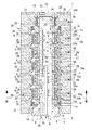
図1は本発明に係るメカニカルシール装置の一例であるロータリジョイントを示す縦断正面図であり、図2は当該ロータリジョイントに使用される本発明に係るメカニカルシールを示す縦断正面図であり、図3は当該ロータリジョイントの横断底面図(断面は図1のIII −III 線に沿う)である。なお、以下の説明において、上下とは図1及び図2における上下をいうものとする。 1 is a longitudinal front view showing a rotary joint as an example of a mechanical seal device according to the present invention, and FIG. 2 is a longitudinal front view showing a mechanical seal according to the present invention used for the rotary joint. Fig. 4 is a transverse bottom view of the rotary joint (the cross section is taken along the line III-III in Fig. 1). In the following description, “upper and lower” refers to the upper and lower sides in FIGS.
図1に示すメカニカルシール装置は、CMP装置における固定側部材である装置本体と回転側部材であるトップリング又はターンテーブルとの間で複数流体を流動させるために使用される多流路形ロータリジョイントである。 The mechanical seal device shown in FIG. 1 is a multi-channel rotary joint that is used to flow a plurality of fluids between a device body that is a stationary member and a top ring or turntable that is a rotating member in a CMP device. It is.
すなわち、このロータリジョイントは、図1に示す如く、固定側部材(CMP装置本体)に取り付けられる筒状のケース体1と回転側部材(トップリング又はターンテーブル)に取り付けられる回転軸体2とを具備し、両部材に形成された流体通路間を相対回転自在に接続するための複数本(N本)の第1流体通路3と1本の第2流体通路103とを有するものである。
That is, the rotary joint includes a cylindrical case body 1 attached to a fixed side member (CMP apparatus main body) and a
各第1流体通路3は、図1に示す如く、スラリ液(ウエハ研磨液等)や水(洗浄用純水等)等の第1流体28を流動させるもので、両体1,2の対向周面部間に形成された環状空間であって一対のメカニカルシール4,4によりシールされた通路接続空間5と、回転軸体2に形成されて通路接続空間5に連通する第1通路6と、ケース体1に形成されて通路接続空間5に連通する第2通路7とからなる。各通路接続空間5をシールする一対のメカニカルシール4,4は、図1に示す如く、上下方向に向きを反対とする形態で配置されている。N本の流体通路3つまりN個の通路接続空間5をシールするために、一対のメカニカルシール4,4からなるシールユニット4Aが軸線方向にN組並列配置されている。各メカニカルシール4は、図2に示す如く、回転軸体2に固定された回転密封環8とケース体1に保持された静止密封環9とを具備するが、各シールユニット4Aにおける一方のメカニカルシール4の回転密封環8と当該シールユニット4Aに隣接するシールユニット4Aにおける一方のメカニカルシール8の回転密封環8とは兼用されている。すなわち、N組のシールユニット4Aを構成するメカニカルシール数は2N個であるが、2N個のメカニカルシール4を構成するために必要とされる回転密封環数はN+1個となる。勿論、静止密封環数はメカニカルシール数に応じた2N個である。なお、図示の例では、N=5としてある。
As shown in FIG. 1, each
ケース体1は、図1に示す如く、内周部が断面円形をなす筒構造体であり、CMP装置等の固定側部材に取り付けられる。ケース体1の内周部には、後述する如く、軸線方向(上下方向)に一定間隔を隔てて並列するN個の環状支持壁10とその上下両側に位置する一対の支持突起11,11とが突設されている。なお、ケース体1は、上下方向に分割された構造をなしており、複数個の分割部分を図示しないボルトにより連結することにより組み立てられる。
As shown in FIG. 1, the case body 1 is a cylindrical structure having an inner peripheral portion having a circular cross section, and is attached to a stationary member such as a CMP apparatus. On the inner periphery of the case body 1, as will be described later, there are N
回転軸体2は、図1に示す如く、円柱状の本体部12と、これに軸線方向(上下方向)に所定間隔を隔てて並列状に嵌合固定されたN+1個の円筒状の保持部13とで構成されており、一対のベアリング14,14によりケース体1の内周部に同心状をなして回転自在に支持されている。なお、最上端に位置する保持部13は、本体部12の上端部に固着された有底円筒状のベアリング受体15の周壁を構成する。また、ベアリング14,14は、ベアリング受体15の外周部とケース体1の上端内周部との間及び本体部12の下端外周部とケース体1の下端内周部との間に介装されている。
As shown in FIG. 1, the
同心をなす両体1,2の対向周面部間(ケース体1の内周部と回転軸体2の外周部との間)には、図1に示す如く、軸線方向(上下方向)に所定間隔を隔てて設けた一対のシール部材16,16により閉塞された環状空間17が形成されている。シール部材16,16は、ケース体1の内周部に嵌合固定されたオイルシール等であり、内周部を最上位の回転密封環8及び最下位の回転密封環8の外周面に押圧接触させることにより、当該回転密封環8とケース体1との間をシールしている。なお、ケース体1には、シール部材16,16でシールされた環状空間17の上下両側において、ドレン1a,1aが設けられている。
As shown in FIG. 1, there is a predetermined distance in the axial direction (vertical direction) between the opposing peripheral surface portions of the two
環状空間17は、図1に示す如く、回転軸体2に設けられたN+1個の回転密封環8とケース体1に形成されたN個の支持壁10と各支持壁10に設けられた一対の静止密封環9とを具備する2N個の端面接触形メカニカルシール3(N組のシールユニット4A)によって、N個の通路接続空間5とN+1個の冷却空間18とに区画シールされている。
As shown in FIG. 1, the
すなわち、回転密封環8は、図1に示す如く、回転軸体2の本体部12に嵌合させると共に、本体部12の下端段部19と最上位の保持部13との間及び保持部13,13相互間に夫々Oリング20を介在させて挟圧させることにより、軸線方向に等間隔を隔てて回転軸体2の外周部に固定されている。各回転密封環8は回転軸線と同心をなす円環状板であり、図2に示す如く、隣接する回転密封環8,8の対向端面を軸線に直交する平滑な環状平面である密封端面(以下「第1密封端面」という)21,21に構成してある。
That is, as shown in FIG. 1, the
各支持壁10は、図1に示す如く、隣接する回転密封環8,8の対向面間に位置して、ケース体1の内周部に突設された環状壁である。すなわち、回転密封環8と支持壁10とは、環状空間17において、軸線方向(上下方向)に交互に配置された状態で並列されている。
As shown in FIG. 1, each
各支持壁10には、その両側に位置する回転密封環8,8の対向端面たる第1密封端面21,21に直対向して、上下一対の静止密封環9,9が軸線方向に移動可能に且つ相対回転不能に保持されている。すなわち、各静止密封環9は、図2に示す如く、支持壁10の内周部にOリング22を介して軸線方向移動可能に嵌合保持されると共に、次のような回転阻止機構により所定範囲での軸線方向移動を許容する状態で回転(ケース体1に対する相対回転)を阻止されている。
In each
この回転阻止機構は、図1〜図3に示す如く、軸線方向(上下方向)に延びる一本のドライブバー24を複数箇所においてケース体1に固定支持し、全静止密封環9を、各静止密封環9の外周部に形成した凹部23を当該固定支持箇所間のドライブバー部分24a,24bに係合させることにより、ケース体1に対する相対回転を阻止するように構成されている。すなわち、ドライブバー24は上下方向に長尺な断面円形のもので、図1に示す如く、その中間部を各支持壁10に形成した貫通孔10aに挿通支持させると共にその端部を各支持突起11に形成した貫通孔11aに挿通支持させることにより、ケース体1に固定支持させてある。そして、軸線方向に並列する静止密封環群のうち、両端に位置する各静止密封環(最上位及び最下位の各静止密封環)9については、その凹部23を支持突起11とこれに対向する支持壁10とで両端支持されたドライブバー部分24bに軸線方向移動可能に係合させてあり、その他の各静止密封環9については、その凹部23を隣接する支持壁10,10で両端支持されたドライブバー部分24aに軸線方向移動可能に係合させてある。なお、隣接する支持壁10,10で両端支持されたドライブバー部分24aには、2個の静止密封環9,9が係合されている。
As shown in FIGS. 1 to 3, this rotation prevention mechanism fixes and supports a
このようにドライブバー24によりケース体1に軸線方向移動可能且つ回転不能に保持された各静止密封環9は、複数のコイルスプリング25により、回転密封環8へと押圧附勢されている。すなわち、各スプリング25は、図1〜図3に示す如く、支持壁10に形成した貫通孔26に挿通保持された状態で、支持壁10に保持された静止密封環9,9間に介挿されていて、当該両静止密封環9,9に共通の附勢手段として機能するように工夫されている。各静止密封環9の端面は、スプリング25により第1密封端面21にこれと同心をなして押圧接触される円環状の第2密封端面27に構成されている。
Thus, each
したがって、各メカニカルシール4にあっては、両密封端面21,27が回転軸体2の回転に伴って相対回転摺接して、周知の端面接触形メカニカルシールと同一機能により、当該相対回転摺接部分の内周側領域と外周側領域をシールすることから、環状空間17が、図1に示す如く、隣接する一対の回転密封環8,8とこれらに押圧接触する一対の静止密封環9,9と回転軸体2の外周部である保持部13とで囲繞形成されるN個の上記内周側領域たる通路接続空間5と、両密封端面21,27の相対回転摺接部分において各通路接続空間5との間をシールされ且つ支持壁10で仕切られるN+1個の上記外周側領域である冷却空間18と、に区画される。
Therefore, in each
回転軸体2には、図1及び図3に示す如く、相互に交差することなく各通路接続空間5に開口するN個の第1通路6が形成されている。すなわち、図1に示す如く、各第1通路6の一端部は回転軸体2の外周部から保持部13を貫通して通路接続空間5に開口されており、その他端部は本体部12の下端部に開口されている。各第1通路6の他端部は、前記回転側部材(トップリング又はターンテーブル)に形成した回転側流路に接続される。
As shown in FIGS. 1 and 3, the
ケース体1には、図1に示す如く、相互に交差しないN個の第2通路7が径方向に貫通形成されている。各第2通路7の一端部は支持壁10を貫通して通路接続空間5に開口されており、その他端部はケース体1の外周部に開口されている。各第2通路7の他端部は、前記固定側部材(CMP装置本体)に形成した固定側流路に接続される。
As shown in FIG. 1, N
したがって、両体1,2には、第1通路6と第2通路7とを通路接続空間5により相対回転自在に接続してなるN本の流体通路3が相互に独立した形態で形成されることになり、N種(同種又は異種)の第1流体28を、図1に矢印で示す如く第2通路7から第1通路6へと、或いは第1通路6から第2通路7へと、混合させることなく流動させることができる。
Accordingly,
全冷却空間18は、図1に示す如く、各支持壁10に形成した貫通孔26により相互に連通されている。ケース体1の上下部には、図1に示す如く、冷却空間18に冷却流体29を給排する供給路30及び排出路31が形成されていて、冷却流体29が全冷却空間18を通過することにより、各メカニカルシール4における密封端面21,27の摺接熱を冷却するように工夫されている。冷却流体29としては、一般に、常温の清浄水や純水等が使用される。
As shown in FIG. 1, the
第2流体通路103は、図1に示す如く、ウエハ加圧用空気やエアーブロ−用空気等の第2流体36を流動させるもので、両体1,2の対向周面部間に形成された環状空間であって一対の弾性シールリング32,32によりシールされた通路接続空間33と、回転軸体2に形成されて通路接続空間33に連通する第1通路34と、ケース体1に形成されて通路接続空間33に連通する第2通路35とからなる。
As shown in FIG. 1, the
図4は図1の要部を拡大して示す縦断正面図であるが、この図4に示す如く、各弾性シールリング32は、環状の本体部40と、本体部40から軸線方向に突出する筒状の内外周リップ部41,42と、内外周リップ部41,42間の環状溝43に充填されたバネ部材44とからなる断面略コ字状の環状体をなすものであり、ベアリング受体15の周壁(保持部)13に対向するケース体1の内周部分に形成した環状凹部37に係合保持されている。両弾性シールリング32,32は、図4に示す如く、環状溝43,43の開口部を対向させた対称形態で配置されていて、ベアリング受体15の周壁13とケース体1との対向周面間に環状の通路接続空間33を形成している。
FIG. 4 is a longitudinal front view showing an enlarged main portion of FIG. 1. As shown in FIG. 4, each
而して、通路接続空間33に流体36が供給されると、流体36が弾性シールリング32,32の環状溝43,43に流入して、流体36の圧力により、軸線方向においては、両シールリング32,32が相互に離間する方向に押圧されて本体部40,40が環状凹部37,37の側面部に押し付けられ、径方向においては、各シールリング32の内外周リップ部41,42がその径方向間隔が広がる方向に押圧変形される。すなわち、環状溝43に流入した流体36の圧力により、各シールリング32のシール部(リップ部41,42の先端部)45,46のシール面(ベアリング受体15の周壁13の外周面及び環状凹部37の内周面)への接触面圧が上昇して、弾性シールリング32によるシール機能が十分に発揮される。かかる接触面圧の上昇程度は、通路接空間33に供給される流体36の圧力に比例する。したがって、上記接触面圧つまりシール力が流体36の圧力に応じて比例的に変化することになり、当該流体36が高圧である場合や圧力変動した場合にも、弾性シールリング32,32によるシール機能が適正且つ良好に発揮されることになり、第2流体通路103における流体流動が漏れを生じることなく良好に行われる。
Thus, when the fluid 36 is supplied to the passage connection space 33, the fluid 36 flows into the
図1に示す如く、第1通路35の一端部は回転軸体2の外周部から保持部13(ベアリング受体15の周壁)を貫通して通路接続空間33に開口されており、その他端部は回転軸体2の本体部12の下端部に開口されている。第1通路35の他端部は、前記回転側部材(トップリング又はターンテーブル)に形成した回転側流路に接続される。また、第2通路36の一端部はケース体1を周方向に貫通して通路接続空間33に開口されており、その他端部はケース体1の外周部に開口されている。第2通路36の他端部は、前記固定側部材(CMP装置本体)に形成した固定側流路に接続される。なお、第2流体通路103は、例えば、ウエハ加圧用空気やエアーブロ−用空気等のガス36を流動させるものとして使用される。
As shown in FIG. 1, one end portion of the
ところで、上記ロータリジョイントでは、シールすべき流体28,29,36の性状に応じてシール手段4,32を使い分けているが、ロータリジョイントの各部材の構成材は、当該部材に要求される機能,機械的強度に応じて選択される他、流体28,29,36の性状,使用目的に応じて選択しておくことが必要であり、一般に、当該流体28,29,36に対して不活性なものを選択しておくことが好ましい。流体28,29,36に対して不活性な構成材は、当該流体28,29,36の性状や使用条件(金属汚染の回避等)との関係において決定されるものであり、例えば、当該流体28,29,36が金属汚染を回避すべきものである場合には、流体28,29,36との接触により金属成分を溶出したり金属粉を発生したりすることがないセラミックスやプラスチックが該当する。また、第1流体通路3を流動する流体28が砥粒等の固形成分を含有するスラリ流体である場合には、当該流体28に接触する部材の構成材として含有固形成分との接触により発塵しないセラミックス,プラスチックが使用される。第1流体通路3又は第2流体通路103を流動する流体28,36が高温流体である場合には、当該流体28,36に接触する部材の構成材として耐熱性を有するセラミックス,プラスチックが使用され、当該流体28,36が腐食性流体である場合には、耐食性ないし耐薬品性を有するセラミックス,プラスチックが使用される。
By the way, in the rotary joint, the sealing means 4 and 32 are properly used according to the properties of the
したがって、密封環8,9については、一般に、接触による摩耗粉等を発生し難い炭化珪素,酸化アルミニウム等のセラミックスで構成しておくことが好ましい。勿論、使用条件によっては、後述のエンジニアリングプラスチックで構成しておくことも可能である。また、密封環8,9以外の流体接触部分(流体が侵入して接触する虞れのある部分を含む)については、流体の性状,使用目的に応じて、砥粒等の固形成分との接触によりパーティクルを発生させることがなく且つ加工による寸法安定性,耐熱性等に優れたPEEK,PES,PC等のエンジニアリングプラスチックや耐食性,耐薬品性に優れたPTFE,PFA,FEP,PVDF等の弗素樹脂で構成しておくことが好ましい。なお、流体通路3,103における流体28,36との接触部分を、選定された材料(以下「選定材料」という)で構成しておく態様としては、流体通路3,103が形成される部材(例えば、ケース体1や回転軸体2の本体部12等の全体)又は部分(例えば、ケース体1における第2通路7,35の形成部分や第1通路6,34を形成する回転軸体2の本体部12)を選定材料で構成しておく場合と、流体28,36との接触部分のみ(例えば、各通路6,7,34,35の内壁面等)をコーティング,パイプ圧入等の手段による選定材料層で構成しておく場合とに大別される。特に、後者は、機械的強度等の面からステンレス鋼等の金属材で構成せざるを得ない部材,部分(例えば、回転軸体2の本体部12)に流体通路3,103を形成しておく場合に有効である。また、ドライピン24aないしドライブバー24は、メカニカルシール4により第1流体通路3との間を遮蔽シールされた冷却空間17に配置されるものであり、専ら冷却流体29が接触するのみであるから、第1流体28の金属汚染を回避する上で、金属材で構成することも可能であるが、第1流体28の金属汚染回避に万全を期すためには(例えば、メカニカルシール4のシール機能低下による両流体28,29の混合があった場合にも当該金属汚染回避を実現するために)は上記エンジニアリングプラスチック等のプラスチック材で構成しておくことが好ましい。また、弾性シールリング32において、本体部40及び内外周リップ部41,42からなる断面略コ字状の環状体はプラスチック,ゴム等の弾性材で一体成形されるが、その構成材たる弾性材の選定はシール条件に応じて行われる。例えば、当該弾性シールリング32によってシールすべき流体36が高温である場合には耐熱性の弾性材を使用し、当該流体36が腐食性を有するものである場合には耐食性の弾性材を使用するが、一般には、自己潤滑性,低摩擦性(摩擦係数0.2〜0.3程度)を有するポリテトラフルオロエチレン(PTFE)等のフッ素樹脂やこれにガラス繊維,炭素繊維,二硫化モリブデン等の充填材を1種以上配合してなる弾性複合材等を使用することが好ましい。この例では、ポリテトラフルオロエチレンにガラス繊維及び二硫化モリブデン又はポリイミド樹脂を配合した、低摩擦性,耐摩耗性等に優れる弾性複合材を使用している。
Therefore, the seal rings 8 and 9 are generally preferably made of ceramics such as silicon carbide and aluminum oxide which hardly generate abrasion powder due to contact. Of course, depending on the use conditions, it is possible to use an engineering plastic described later. In addition, fluid contact parts other than the seal rings 8 and 9 (including parts that may be in contact with the fluid) contact with solid components such as abrasive grains depending on the properties and intended use of the fluid. Prevents the generation of particles and engineering plastics such as PEEK, PES, and PC with excellent dimensional stability and heat resistance due to processing, and fluorine resins such as PTFE, PFA, FEP, and PVDF with excellent corrosion resistance and chemical resistance It is preferable to comprise. In addition, as an aspect in which the contact portions of the
以上のように構成されたメカニカルシール装置たるロータリジョイントによれば、N本の第1流体通路3及び1本の第2流体通路103が各々独立して形成されていることから、N+1種の流体28,36を回転側流体通路と固定側流体通路との間で混在させることなく良好に流動させることができ、それらの流動状態制御も各別に行うことができる。
According to the rotary joint as the mechanical seal device configured as described above, the N first
そして、各第1流体通路3の相対回転部分(通路接続空間5)をシールするメカニカルシール4にあっては、ドライブバー24が各静止密封環8との係合個所の両側において保持壁10又は保持突起11に支持(両端支持)されていることから、ドライブバー24つまり全ドライブバー部分24a,24bを金属材で構成した場合は勿論、金属材に比して強度的に劣るプラスチック材で構成した場合にも、冒頭で述べた如き問題を生じることがなく、ドライブピン機能が安定して発揮されることになる。したがって、ドライブピン機能の低下,喪失によりメカニカルシール4のシール機能が低下,喪失するようなことがなく、第1流体28の流動を良好に行うことができる。また、一般に、ドライブピン機能の低下,喪失を防止するために、静止密封環9に複数の凹部23を形成して、各凹部23にドライブピン24a,24bを係合させておくように工夫されるが、上記の如くドライブピン(ドライブバー部分)24a,24bを両端支持構造としておくと、各静止密封環9に複数の凹部23を形成しておかずとも、つまり各静止密封環9を複数本のドライブピン24a(ドライブバー24)で係止しておかずともドライブピン機能の低下を防止することができ、図3に示す如く、全静止密封環9の回転阻止を1本のドライブバー24で十分に行うことが可能となり、メカニカルシール構造の簡略化を図ることができる。
In the
また、すべてのメカニカルシール4の静止密封環9の相対回転を1本のドライブバー24で阻止するように構成しているから、各メカニカルシール4毎に各別のドライブピンを設ける場合に比して、メカニカルシール構造の簡略化を図ることができる。特に、多数のメカニカルシール4を必要とするロータリジョイント等のメカニカルシール装置にあっては、上記した如く全静止密封環9の回転阻止を1本のドライブバー24で行うことができることと相俟って、かかる効果(メカニカルシール構造の簡略化)は著しい。
Further, since the relative rotation of the stationary sealing rings 9 of all the
ところで、メカニカルシール4にあっては、密封環8,9の接触部分(密封端面21,27)が発熱して焼き付く等の虞れがあり、特に、シールすべき第1流体28が気体である場合や液体であっても吸引排出等によりドライ条件となる場合には、かかる虞れが強くなる。しかし、上記したロータリジョイントにあっては、密封環8,9及びその接触部分は冷却空間18を流動する冷却流体29により冷却されて、上記した虞れは生じないから、第1流体28が気体である場合やドライ条件で使用される場合においても、密封環8,9の相対回転摺接作用が円滑に行われて、良好なシール機能が発揮される。
By the way, in the
ところで、複数本の流体通路を必要とするロータリジョイントにあっては、すべての流体通路のシール手段としてメカニカルシール4を採用した場合には、ロータリジョイントの全長(軸線方向長さ)が長大化することになる。しかし、流体通路を流動させる流体の性状によっては、メカニカルシール4のような高度のシール手段を使用する必要がない場合もある。そこで、上記したロータリジョイントにあっては、第1流体通路3と第2流体通路103とでシールすべき流体28,36の性状に応じてシール手段4,32を使い分けるようにし、メカニカルシール4のような高度のシール手段によってシールさせる必要のない第2流体36については、シール手段としてメカニカルシール4に比して構造簡単にして小型の弾性シールリング32を使用している。その結果、ロータリジョイントの全長を可及的に短尺化し得て、ロータリジョイントの小型化及び構造簡略化を効果的に図ることができる。なお、弾性シールリング32,32でシールされる第2流体通路103の設置数は、必要に応じて任意とできる。複数の第2流体通路103を設ける場合、各第2流体通路103における一方の弾性シールリング32をこれに隣接する第2流体通路103における一方の弾性シールリング32と兼用させることができる。
By the way, in a rotary joint that requires a plurality of fluid passages, when the
なお、本発明は、上記した実施の形態に限定されるものでなく、本発明の基本原理を逸脱しない範囲において適宜に変更,改良することができる。 The present invention is not limited to the above-described embodiment, and can be appropriately changed and improved without departing from the basic principle of the present invention.
例えば、上記したロータリジョイントにおいて、図5に示す如く、ドライブバー24の両端部24c,24cはケース体1に支持させず、メカニカルシール群の両端に位置するメカニカルシール(最上位及び最下位のメカニカルシール)4,4については、各静止密封環9を支持壁10から突出するドライブバー24の端部24c,24cに係合させるようにしてもよい。この場合、両静止密封環9,9に係合するドライブバー端部24c,24cは夫々片持ち支持構造をなすものであるが、ドライブバー端部24c,24cが支持壁群10に貫通支持されているドライブバー24の両端部であるから、ドライブピンの基端部を固定支持させた場合と異なって、冒頭で述べた如き問題は生じない。
For example, in the above-described rotary joint, as shown in FIG. 5, both
また、本発明は、ロータリジョイント以外のメカニカルシール装置にも適用することができる。 The present invention can also be applied to mechanical seal devices other than rotary joints.
1 ケース体
2 回転軸体
3 第1流体通路
4 メカニカルシール
4A シールユニット
5 通路接続空間(相対回転部分の外周領域)
6 第1通路
7 第2通路
8 回転密封環
9 静止密封環
10 支持壁
10a 貫通孔
11 支持突起
11a 貫通孔
18 冷却空間(相対回転部分の外周領域)
21 密封端面
24 ドライブバー
24a ドライブバー部分
24b ドライブバー部分
24c ドライブバーの端部
27 密封端面
28 第1流体
29 冷却流体
DESCRIPTION OF SYMBOLS 1
6
21 Sealed end face 24
Claims (9)
全静止密封環を、各静止密封環の外周部に形成した凹部をケース体に複数箇所を固定支持させた一本のドライブバーに係合させることにより、ケース体に対する相対回転を阻止するように構成してあることを特徴とするメカニカルシールシール装置。 A mechanical seal device comprising a plurality of mechanical seals arranged in parallel in the axial direction, wherein each mechanical seal is held by a rotary seal ring fixed to the rotary shaft body and a cylindrical case body so as to be movable in the axial direction. In a mechanical seal device comprising a stationary seal ring, and configured to seal between the inner and outer peripheral regions of the relative rotation part by relative rotation of opposing end faces of both seal rings,
To prevent relative rotation with respect to the case body by engaging the recesses formed in the outer peripheral part of each stationary seal ring with a single drive bar having the case body fixedly supported at a plurality of locations. A mechanical seal sealing device characterized by being configured.
Priority Applications (1)
| Application Number | Priority Date | Filing Date | Title |
|---|---|---|---|
| JP2008189187A JP4555878B2 (en) | 2008-07-22 | 2008-07-22 | Mechanical seal device |
Applications Claiming Priority (1)
| Application Number | Priority Date | Filing Date | Title |
|---|---|---|---|
| JP2008189187A JP4555878B2 (en) | 2008-07-22 | 2008-07-22 | Mechanical seal device |
Related Parent Applications (1)
| Application Number | Title | Priority Date | Filing Date |
|---|---|---|---|
| JP2004354116A Division JP4250585B2 (en) | 2004-12-07 | 2004-12-07 | Mechanical seal device |
Publications (2)
| Publication Number | Publication Date |
|---|---|
| JP2008286405A JP2008286405A (en) | 2008-11-27 |
| JP4555878B2 true JP4555878B2 (en) | 2010-10-06 |
Family
ID=40146291
Family Applications (1)
| Application Number | Title | Priority Date | Filing Date |
|---|---|---|---|
| JP2008189187A Active JP4555878B2 (en) | 2008-07-22 | 2008-07-22 | Mechanical seal device |
Country Status (1)
| Country | Link |
|---|---|
| JP (1) | JP4555878B2 (en) |
Families Citing this family (2)
| Publication number | Priority date | Publication date | Assignee | Title |
|---|---|---|---|---|
| JP2011074931A (en) * | 2009-09-29 | 2011-04-14 | Ihi Corp | Sealing device for combustible gas compressor |
| JP2014114848A (en) * | 2012-12-07 | 2014-06-26 | Nippon Pillar Packing Co Ltd | Rotary joint |
Citations (2)
| Publication number | Priority date | Publication date | Assignee | Title |
|---|---|---|---|---|
| JP2001141150A (en) * | 1999-11-18 | 2001-05-25 | Nippon Pillar Packing Co Ltd | Multiple flow passage type rotary joint |
| JP2002174379A (en) * | 2000-12-05 | 2002-06-21 | Nippon Pillar Packing Co Ltd | Multiple passage type rotary joint |
-
2008
- 2008-07-22 JP JP2008189187A patent/JP4555878B2/en active Active
Patent Citations (2)
| Publication number | Priority date | Publication date | Assignee | Title |
|---|---|---|---|---|
| JP2001141150A (en) * | 1999-11-18 | 2001-05-25 | Nippon Pillar Packing Co Ltd | Multiple flow passage type rotary joint |
| JP2002174379A (en) * | 2000-12-05 | 2002-06-21 | Nippon Pillar Packing Co Ltd | Multiple passage type rotary joint |
Also Published As
| Publication number | Publication date |
|---|---|
| JP2008286405A (en) | 2008-11-27 |
Similar Documents
| Publication | Publication Date | Title |
|---|---|---|
| JP4250585B2 (en) | Mechanical seal device | |
| KR102394592B1 (en) | Multiple flow passage type rotary joint | |
| JP3580774B2 (en) | Multi-channel rotary joint | |
| US6508472B2 (en) | Multi-channel rotary joint | |
| EP2799752B1 (en) | Multi-port rotary joint | |
| US6530397B2 (en) | Multi-channel rotary joint | |
| BRPI0612716A2 (en) | shaft seal assembly | |
| US10371300B2 (en) | Rotary joint | |
| WO2009158695A1 (en) | Split bearing assemblies, air-cooled heat exchangers and related methods | |
| JP5622258B2 (en) | Multi-channel rotary joint | |
| JP2007278424A (en) | Rotary joint | |
| JP4555878B2 (en) | Mechanical seal device | |
| JP5124784B2 (en) | Mechanical seal device | |
| JP4929314B2 (en) | Multi-channel rotary joint | |
| JP4566159B2 (en) | Multi-channel rotary joint | |
| JP4391205B2 (en) | Mechanical seal device | |
| JP6490994B2 (en) | Multi-channel rotary joint | |
| JP6490993B2 (en) | Multi-channel rotary joint | |
| JP6490992B2 (en) | Rotary joint | |
| JP2009275900A (en) | Rotary joint for strongly corrosive liquid | |
| JP3105195B2 (en) | Rotary joint | |
| JP7003009B2 (en) | Rotary joint |
Legal Events
| Date | Code | Title | Description |
|---|---|---|---|
| A621 | Written request for application examination |
Free format text: JAPANESE INTERMEDIATE CODE: A621 Effective date: 20080819 |
|
| A977 | Report on retrieval |
Free format text: JAPANESE INTERMEDIATE CODE: A971007 Effective date: 20100630 |
|
| TRDD | Decision of grant or rejection written | ||
| A01 | Written decision to grant a patent or to grant a registration (utility model) |
Free format text: JAPANESE INTERMEDIATE CODE: A01 Effective date: 20100713 |
|
| A01 | Written decision to grant a patent or to grant a registration (utility model) |
Free format text: JAPANESE INTERMEDIATE CODE: A01 |
|
| A61 | First payment of annual fees (during grant procedure) |
Free format text: JAPANESE INTERMEDIATE CODE: A61 Effective date: 20100716 |
|
| FPAY | Renewal fee payment (event date is renewal date of database) |
Free format text: PAYMENT UNTIL: 20130723 Year of fee payment: 3 |
|
| R150 | Certificate of patent or registration of utility model |
Free format text: JAPANESE INTERMEDIATE CODE: R150 Ref document number: 4555878 Country of ref document: JP Free format text: JAPANESE INTERMEDIATE CODE: R150 |
|
| FPAY | Renewal fee payment (event date is renewal date of database) |
Free format text: PAYMENT UNTIL: 20140723 Year of fee payment: 4 |