JP4555680B2 - CD recorder / printer device - Google Patents
CD recorder / printer device Download PDFInfo
- Publication number
- JP4555680B2 JP4555680B2 JP2004509943A JP2004509943A JP4555680B2 JP 4555680 B2 JP4555680 B2 JP 4555680B2 JP 2004509943 A JP2004509943 A JP 2004509943A JP 2004509943 A JP2004509943 A JP 2004509943A JP 4555680 B2 JP4555680 B2 JP 4555680B2
- Authority
- JP
- Japan
- Prior art keywords
- disk
- processing
- support
- carriage
- disc
- Prior art date
- Legal status (The legal status is an assumption and is not a legal conclusion. Google has not performed a legal analysis and makes no representation as to the accuracy of the status listed.)
- Expired - Fee Related
Links
- 230000007723 transport mechanism Effects 0.000 claims description 20
- 238000000034 method Methods 0.000 claims description 16
- 230000008569 process Effects 0.000 claims description 8
- 230000007246 mechanism Effects 0.000 claims description 5
- 238000007639 printing Methods 0.000 abstract description 32
- 230000032258 transport Effects 0.000 description 8
- 238000007796 conventional method Methods 0.000 description 2
- 238000010586 diagram Methods 0.000 description 2
- 230000004048 modification Effects 0.000 description 2
- 238000012986 modification Methods 0.000 description 2
- 238000003854 Surface Print Methods 0.000 description 1
- 230000009471 action Effects 0.000 description 1
- 238000005452 bending Methods 0.000 description 1
- 230000008878 coupling Effects 0.000 description 1
- 238000010168 coupling process Methods 0.000 description 1
- 238000005859 coupling reaction Methods 0.000 description 1
- 239000012634 fragment Substances 0.000 description 1
- 238000003672 processing method Methods 0.000 description 1
- 230000001360 synchronised effect Effects 0.000 description 1
- 238000007651 thermal printing Methods 0.000 description 1
Images


Classifications
-
- G—PHYSICS
- G11—INFORMATION STORAGE
- G11B—INFORMATION STORAGE BASED ON RELATIVE MOVEMENT BETWEEN RECORD CARRIER AND TRANSDUCER
- G11B17/00—Guiding record carriers not specifically of filamentary or web form, or of supports therefor
- G11B17/08—Guiding record carriers not specifically of filamentary or web form, or of supports therefor from consecutive-access magazine of disc records
-
- G—PHYSICS
- G11—INFORMATION STORAGE
- G11B—INFORMATION STORAGE BASED ON RELATIVE MOVEMENT BETWEEN RECORD CARRIER AND TRANSDUCER
- G11B23/00—Record carriers not specific to the method of recording or reproducing; Accessories, e.g. containers, specially adapted for co-operation with the recording or reproducing apparatus ; Intermediate mediums; Apparatus or processes specially adapted for their manufacture
- G11B23/38—Visual features other than those contained in record tracks or represented by sprocket holes the visual signals being auxiliary signals
- G11B23/40—Identifying or analogous means applied to or incorporated in the record carrier and not intended for visual display simultaneously with the playing-back of the record carrier, e.g. label, leader, photograph
-
- B—PERFORMING OPERATIONS; TRANSPORTING
- B41—PRINTING; LINING MACHINES; TYPEWRITERS; STAMPS
- B41J—TYPEWRITERS; SELECTIVE PRINTING MECHANISMS, i.e. MECHANISMS PRINTING OTHERWISE THAN FROM A FORME; CORRECTION OF TYPOGRAPHICAL ERRORS
- B41J13/00—Devices or arrangements of selective printing mechanisms, e.g. ink-jet printers or thermal printers, specially adapted for supporting or handling copy material in short lengths, e.g. sheets
- B41J13/10—Sheet holders, retainers, movable guides, or stationary guides
- B41J13/22—Clamps or grippers
-
- B—PERFORMING OPERATIONS; TRANSPORTING
- B41—PRINTING; LINING MACHINES; TYPEWRITERS; STAMPS
- B41J—TYPEWRITERS; SELECTIVE PRINTING MECHANISMS, i.e. MECHANISMS PRINTING OTHERWISE THAN FROM A FORME; CORRECTION OF TYPOGRAPHICAL ERRORS
- B41J3/00—Typewriters or selective printing or marking mechanisms characterised by the purpose for which they are constructed
- B41J3/407—Typewriters or selective printing or marking mechanisms characterised by the purpose for which they are constructed for marking on special material
- B41J3/4071—Printing on disk-shaped media, e.g. CDs
-
- G—PHYSICS
- G11—INFORMATION STORAGE
- G11B—INFORMATION STORAGE BASED ON RELATIVE MOVEMENT BETWEEN RECORD CARRIER AND TRANSDUCER
- G11B23/00—Record carriers not specific to the method of recording or reproducing; Accessories, e.g. containers, specially adapted for co-operation with the recording or reproducing apparatus ; Intermediate mediums; Apparatus or processes specially adapted for their manufacture
-
- G—PHYSICS
- G11—INFORMATION STORAGE
- G11B—INFORMATION STORAGE BASED ON RELATIVE MOVEMENT BETWEEN RECORD CARRIER AND TRANSDUCER
- G11B7/00—Recording or reproducing by optical means, e.g. recording using a thermal beam of optical radiation by modifying optical properties or the physical structure, reproducing using an optical beam at lower power by sensing optical properties; Record carriers therefor
- G11B7/24—Record carriers characterised by shape, structure or physical properties, or by the selection of the material
- G11B7/26—Apparatus or processes specially adapted for the manufacture of record carriers
Abstract
Description
本発明は、プラスチック製ディスク上に記録された音楽、映像、その他の情報を含むCDのデジタル情報を記録するための、結合されたディスクレコーダとラベルプリンタに関する。記録時にディスク上へのラベル情報印刷を行って、ディスク処理の終了とする。 The present invention relates to a combined disc recorder and label printer for recording digital information on a CD including music, video and other information recorded on a plastic disc. At the time of recording, label information is printed on the disc, and the disc processing ends.
米国特許第6、327、230号に開示されているプリンタのように、同じユニット内に結合されたディスク用レコーダの技術分野においては、プラスチックディスク上へ印刷するための装置が提供されている。しかし、その第6、327、230号記載の装置は、ベンディングシーケンスをもち、印刷と記録とでは全体に異なる機構を使っている。異なる処理位置間でディスクを搬送するディスクの「ピック(picks)」つまりホルダは、プリンタと分離している。 In the technical field of disc recorders coupled in the same unit, such as the printer disclosed in US Pat. No. 6,327,230, an apparatus for printing on plastic discs is provided. However, the apparatus described in No. 6,327,230 has a bending sequence and uses different mechanisms for printing and recording as a whole. The “picks” or holders of the discs that transport the discs between different processing positions are separate from the printer.
積み重ねたディスクの山から、あるいは、トレーや支持体から個々に1枚のディスクを取り上げる動作などを含む、中央孔をもつディスクの取り扱い操作方法は、周知である。数多くの異なる種類の「ピック」つまりグリッパが開発されており、コスタス(Costas)による米国特許第5、873、692号にはその一種類が、米国特許第6、111、847号や第5、934、865号などにはその他の複数の種類のグリッパが開示されている。 Methods for handling discs with a central hole are well known, including the action of picking up a single disc from a stack of stacked discs or from a tray or support individually. A number of different types of “picks” or grippers have been developed, and US Pat. No. 5,873,692 by Costas, one of which is US Pat. Nos. 6,111,847 and 5, A plurality of other types of grippers are disclosed in Japanese Patent No. 934,865.
また、ディスク上に「ラベル」情報を直接に印刷する方法も、周知である。ディスクへの記録やコピーも同様であり、一例として、ミラー(miller)の米国特許第6、141、298号に開示されているが、特に、記録時にディスク上への情報印刷が確実に行え、使用が容易なインクジェット式プリンタとの最小規模での統合が望まれている。 Also well known is the method of printing “label” information directly on a disc. The same applies to recording and copying on a disc, and as an example, it is disclosed in US Pat. No. 6,141,298 of Miller. In particular, information can be printed on a disc reliably during recording. It is desired to integrate with an inkjet printer that is easy to use on a minimum scale.
本発明は、コンパクトディスクのレコーダ(コピー機、焼付器)とプリンタとを結合して、使用される装置を最小限にし、好ましくは、複数の処理位置間で、ディスクを配列させるためのディスク搬送器と印刷ヘッドとの共通支持軸を利用する。未記録ディスクは、通常はプラスチック製ディスクであって、CD、DVD、記録可能DVDなどのコンパクトディスク、ミニディスク、並びにネームバッジディスクと呼ばれる。ディスクの形状は円形に限らず、直線で囲まれた、もしくは平行な端部および丸くなった、もしくは曲がった端部を有していても構わない。 The present invention combines a compact disk recorder (copier, burner) and printer to minimize the equipment used, and preferably to transport a disk for arranging the disks between a plurality of processing positions. A common support shaft is used for the container and the print head. Unrecorded discs are usually plastic discs, and are called CDs, DVDs, compact discs such as recordable DVDs, minidiscs, and name badge discs. The shape of the disk is not limited to a circle, and may have a straight end or a parallel end and a rounded or bent end.
本発明の特徴として、ディスク面に印刷を行うプリンタは、電動にてベアリング軸に沿って移動できるインクジェット式プリンタである。印刷時には印刷ヘッドが横方向に前記軸に沿って移動し、記録されるアイテムはその軸に直交する方向に移動する。図示するように、ディスク用「ピッカー(picker)」つまりグリッパの取り付けにも前記ベアリング軸を使用しているため、装置サイズがコンパクトになり、個々のフレームや支持部品も最小限にでき、よりコンパクトな構成、および、より効率的な支持部品利用が可能となる。また、ピッカーの取り付け用に、別途の平行軸やガイドを利用しても構わない。 As a feature of the present invention, the printer that prints on the disk surface is an ink jet printer that can be electrically moved along the bearing shaft. During printing, the print head moves laterally along the axis, and the item to be recorded moves in a direction perpendicular to the axis. As shown in the figure, the above-mentioned bearing shaft is also used for mounting a “picker” for discs, that is, a gripper, so that the size of the device is compact, individual frames and supporting parts can be minimized, and more compact Structure and more efficient support component utilization are attained. Further, a separate parallel shaft or guide may be used for mounting the picker.
具体的に、CDプリンタは周知構造のプリンタが利用できる。米国特許第6、148、722号には、CDを感熱印刷ヘッドへ搬送するCD支持トレイを備えた感熱プリンタが開示されている。その米国特許第6、148、722号におけるCDつまりディスクの支持トレイ用駆動装置は、インクジェット式プリンタと共に使用することもできる。また、市販されているディスクレコーダやコピー機も、本発明の装置にて使用可能である。コピー機やプリンタは、いずれも、制御プログラムによりレコーダやプリンタのハウジングから拡張できるトレイを備えている。トレイは、各処理のため対応する各トレイ上にディスクを載置することができる位置まで拡張できる。未記録ディスクは、スタック、つまり格納領域に格納されており、垂直方向に移動可能なアームに取り付けられたディスクグリッパやピッカーヘッドにより1枚ずつ持ち上げられる。アームは、印刷ヘッドの取り付けに使用するベアリング軸に沿ってスライド移動可能なキャリッジに取り付けられる。 Specifically, a printer having a known structure can be used as the CD printer. U.S. Pat. No. 6,148,722 discloses a thermal printer with a CD support tray for transporting a CD to a thermal printing head. The CD or disc support tray drive in US Pat. No. 6,148,722 can also be used with an ink jet printer. Commercially available disk recorders and copiers can also be used with the apparatus of the present invention. Both copiers and printers have trays that can be expanded from the recorder or printer housing by a control program. The tray can be extended to a position where a disk can be placed on each corresponding tray for each process. Unrecorded disks are stored in a stack, that is, a storage area, and are lifted one by one by a disk gripper or a picker head attached to an arm movable in the vertical direction. The arm is attached to a carriage that is slidable along a bearing axis that is used to attach the print head.
前記動作は、順番に行われる。例えば、未記録ディスクは、ディスク供給部からつかみ上げられ、ディスク焼付器つまりレコーダに対応したトレイ上方の位置まで搬送され、そこで落下される。プログラムされた制御により、ディスクがCD焼付器つまりレコーダまで移動され、情報の記録後、トレイは、ディスクグリッパやピッカーによりディスクをトレイから持ち上げた位置で保持してCD焼付器つまりレコーダ側のトレイをクリアにするためディスクにアクセスできる拡張位置まで戻される。 The operations are performed in order. For example, an unrecorded disc is picked up from a disc supply unit, conveyed to a position above a tray corresponding to a disc burner, that is, a recorder, and dropped there. Under programmed control, the disc is moved to the CD burner or recorder, and after the information is recorded, the tray holds the disc at the position where the disc is lifted from the tray by a disc gripper or picker, and the tray on the CD burner or recorder side is held. It is returned to the extended position where the disk can be accessed for clearing.
次に、プログラムは、レコーダつまり焼付器側トレイを引っ込めて、プリンタ側トレイを拡張させる。拡張したプリンタ側トレイは、拡張されたレコーダ側トレイの位置とほぼ整列するため、グリッパによって、持ち上げられた位置から下降、つまりプリンタ側トレイ上までつまんで下降させることができる。CDが開放され、ピッカーが引っ込められると、プリンタが動作し、印刷プログラムに従って新たに記録されたディスク面にラベル情報の印刷が行われる。印刷動作が完了すると、プログラムされた制御はピッカーにプリンタ側トレイからCDを再度もち上げさせ、このディスクを処理完了ディスクつまりCDが積み上げられた格納領域へと搬送させる。 Next, the program retracts the recorder, that is, the burner side tray, and expands the printer side tray. Since the expanded printer-side tray is substantially aligned with the position of the expanded recorder-side tray, the gripper can be lowered from the raised position, that is, pinched down onto the printer-side tray. When the CD is released and the picker is retracted, the printer operates and the label information is printed on the newly recorded disc surface according to the printing program. When the printing operation is complete, the programmed control causes the picker to pick up the CD again from the printer-side tray and transport the disk to a processing complete disk, that is, a storage area on which the CD is stacked.
ピッカーつまりグリッパは、プリンタの印刷ヘッドと同じベアリング軸およびサポート上に装着されたキャリッジ上のアームに取り付けられている。これにより、分離した搭載部材を省略でき、装置をよりコンパクトにでき、かつ動作信頼性を向上させることができる。ディスクピックアップ用のアームを装備したキャリッジは、レールに沿って移動できるよう印刷ヘッドとラッチ連結される。これにより、ピッカーもしくはグリップキャリッジ用の駆動装置を配備する必要がなくなる。グリップつまりピックは、ステップモータにより駆動される別途設置のネジ付きロッドにより垂直方向に移動できる。ゆえに、ディスクとトレイとの位置整列が、非常に簡単となる。 The picker or gripper is attached to an arm on the carriage mounted on the same bearing shaft and support as the print head of the printer. Thereby, the separated mounting member can be omitted, the apparatus can be made more compact, and the operation reliability can be improved. A carriage equipped with a disk pickup arm is latched to the print head so as to move along the rail. This eliminates the need to provide a picker or grip carriage drive. The grip or pick can be moved vertically by a separately installed threaded rod driven by a step motor. Therefore, the position alignment between the disc and the tray becomes very simple.
ピッカーアームの取付構造の第2の実施例では、前記アームが、垂直ネジ支柱に取り付けられたアーム軸まわりに枢支回転できる。枢支回転により、枢支不可のアームよりも遠い位置にあるCD格納ホッパーの上方位置までピッカーを移動させることができる。アームは、キャリッジの一方の移動方向の端に達すると、所定距離だけ時計方向に回転し、同様に、キャリッジの他方の移動方向の端に達すると、逆時計方向に回転する。 In a second embodiment of the picker arm mounting structure, the arm can pivot about an arm axis mounted on a vertical screw column. By pivoting, the picker can be moved to a position above the CD storage hopper located farther from the arm that cannot be pivoted. The arm rotates clockwise by a predetermined distance when it reaches the end of one movement direction of the carriage, and similarly rotates counterclockwise when it reaches the end of the other movement direction of the carriage.
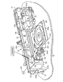
図の符号10で示すディスクのプリンタ/レコーダ焼付装置は、横方向に延びており、ベースプレート15上の支持された端部支持体13を備えるフレーム12を有する。フレーム12は、例えば、米国ケンタッキー州レキシントン(Lexington Kentucky)のレックスマーク インタナショナル インコーポレイテッド(Lexmark International, Inc.)が製造販売するレックスマーク(Lexmark)製インクジェットプリンタなどの従来のインクジェット式プリンタのフレーム部であり、印刷ヘッドやその他の部品の横方向への移動の際の安定支持体として機能する。またフレーム12には、印刷ヘッド16をスライド移動可能に設置するための横方向ベアリング支持軸14が備わっている。印刷ヘッド16には、印刷ヘッド16が印刷用に安定支持されてベアリング支持軸14に沿って横方向に移動できるよう、フレーム12の上側のトラック12Aの上端17に適当なガイドが設けられている。印刷ヘッド16は図示の如く2個のインクカートリッジ16Aと16Bを備え、印刷ヘッドのガイドや印刷ヘッド駆動方法がレックスマーク製プリンタにおける在来の技術であるため、図では概略的に図示されている。
The disc printer / recorder printing apparatus, indicated by
印刷ヘッド16の駆動ベルト18は、20で示す適当なモータで駆動され、その駆動にはインクジェット式印刷ヘッドに一般的に利用されている従来の方法が使用される。駆動部は軸14に沿って印刷ヘッド16を移動し、印刷動作を実行できるよう、中央制御器19によってプリンタ側トレイの移動に同期される。
The
プリンタフレーム、ガイド軸、印刷ヘッド、印刷ヘッド駆動部は、CDトレイやトレイ駆動部と同様に従来の構成となっている。 The printer frame, the guide shaft, the print head, and the print head drive unit have the same configuration as the CD tray and the tray drive unit.
中央制御器19は、装置10の多様な動作、つまり、印刷ヘッドモータ20の制御や、後で説明する、CD記録動作や記録されたCD上面にラベルを印刷する動作を含む制御をするためのものである。
The
プリンタには、その上面にラベルが印刷されるコンパクトディスク用のディスク支持トレイ22を備えたCDプリンタハウジング23が設けられている。図示のように、ディスクつまりCD25Aはそのトレイ22上に載置されている。ディスク25Aがトレイ22上にあるとき、トレイ22は図1に示す位置まで移動することができる。つまり、トレイ上のディスク上面にラベル印刷できるよう、トレイ22は印刷ヘッド16に対して正しく調整された駆動部により移動されるのである。トレイ22は、印刷ヘッドのベアリング支持軸14に直交してハウジング23から内外方向へ移動すると共に、印刷ヘッド16は、米国特許第6、148、722号や第6、302、601号などに記載のプリンタおよびその移動の開示内容にほぼ準拠するよう、印刷動作を行うためベアリング支持軸14に沿って移動する。図1に示すように、プリンタ側トレイ22が手前に伸びた位置にあるときに、印刷動作が実行されるよりも前に、ディスク上面への記録つまり焼付の動作がまず行われる。
The printer is provided with a
ディスクつまりCD25Aには、標準の中央孔が設けられており、ディスクの搬送のため、適当な方法でアーム28に取り付けられたディスクグリッパつまりピッカー24とキャリッジ30を備えたディスクを操作するためのディスク搬送機構30Aが設けられている。グリッパ24はどのような形状でも構わないが、図示のグリッパ24は、CDの中央孔に挿入できる端部24Aをもつ3本の垂直フィンガーブレード24Bを備える。アーム28に取り付けられているソレノイド26は、グリッパのブレード24Bの端部24Aを拡げて、処理されるCDの中央孔の内側面に係合するよう動作する。図1には未記録CDの供給部が図示されていないが、図2と図5には、未記録CDの山46が図示されおり、この山46はグリッパ24がフレームの一端(図では左端)の「ホーム(home)」ポジションにある場合に、下方配置つまりアーム28とグリッパ24の下側に配置される。
The disc or
アーム28とソレノイド26はキャリッジ30に取り付けられており、ディスク搬送機構30Aの一部を構成している。キャリッジ30は、印刷ヘッド16と同様に、ベアリング支持軸14にスライド移動可能に取り付けられていて、移動を安定させるためガイド端12Aに係合可能である。キャリッジ30は、該キャリッジを位置決めするために、印刷ヘッド16にラッチ結合またはフック結合することにより、かつ、印刷ヘッド駆動ベルト18とモータ20を使って、ベアリング支持軸14に沿って移動する。キャリッジ30のラッチ結合やフック結合、および、移動は、制御器19により全体的に制御される。
The
キャリッジ30には、2本一対の垂直支柱31Bでガイドされるハブ31Aを備えた中央ブロック31が設けられている。中央ブロック31は、垂直ネジ棒つまり支柱32にネジ移動可能に取り付けられたネジ溝付きハブ31Cを備える。ネジ棒つまりネジ支柱32は、キャリッジ30の上側プレート33Aと下側プレート33B上に回転可能に支持されている。ネジ棒つまりネジ支柱32はキャリッジ30と共に移動するし、アーム28はそのネジ支柱32に支持されているので、ステップモータ33により支柱32を回転することにより、支柱32に沿って縦方向に移動できる。ステップモータ33は、キャリッジ30の上側プレート33A上に設けられている。ステップモータ33は、制御器19に制御されて支柱32を回転させ、アーム28を上下に移動させる。さらに、キャリッジ30には、上下プレート33Aと33Bの間に接合された1対の垂直ガイド支持壁部35Aと35Bが設けられている。ガイド壁部35Aと35Bは、ガイド移動を安定にするため、ガイドレール12Aと係合するガイドフック37Aと37Bをそれぞれ備える。
The
キャリッジ30の、ガイドレール12Aにガイドされ、かつ、ベアリング支持軸14に沿った移動は、キャリッジ30の上側壁部35Aに枢支取り付けされたラッチレバー29を使ってキャリッジ30を脱着可能に印刷ヘッドと連結させることにより実行することができる。つまり、キャッチレバーであるラッチレバー29は壁部のスロット孔35Cに挿入され、その基端部35Eが 壁部35Aに設けられた枢支ピン29Aに取り付けてある。ラッチレバー29は、他方の壁部35Bのスロット孔内に伸びており、外側端にはキャッチつまりフック29B(図5、6、7、8を参照)を備える。キャッチによって印刷ヘッドの突起部34にレバーの傾斜端29Eが係合しているとき、印刷ヘッド16がキャリッジ30に対して移動すると、ラッチレバー29のフック部29Bは上方向へ枢支移動される。アーム28が上昇し、中央ブロック31のフランジ端31Fがタブ片29Tと係合して、フック29Bを持ち上げる。フック29Bは、印刷ヘッド16の突起部つまり係合部34から離脱できる高さまで持ち上げられる。
The
グリッパ23に把持されたCDが処理位置間を搬送されるアーム28の垂直方向位置は、アーム28がラッチレバー29を持ち上げる位置よりも低い。印刷ヘッド16は、ラッチ動作を自動的に行うため、駆動ベルト18により高速でキャリッジ30方向へ移動される。
The vertical position of the
ラッチレバー29は、必要に応じてバネの力によりそのフック端29Bを下方へ付勢できる。印刷ヘッド16をベアリング支持軸14に沿って移動させるため、ベルト18とモータ20が使われている。ラッチレバー29と接合させることにより、キャリッジ30も支持軸14に沿って移動できる。
The
記録と印刷のサイクル動作中において、まず最初に、アーム28が下方へ移動し、グリッパ24が格納トレイつまりホッパ46A(図5参照)内の供給ディスクの山46のうちの1枚の未記録ディスク25Aに到達する。ソレノイド26が駆動され、グリッパ24がその1枚のCDつまりディスクをつかむ。駆動モータ33の動作により、アーム28が、グリッパ24に把持されたディスクが横方向へ移動できる位置まで持ち上げられる。印刷ヘッド16は、モータ20がベルト18を駆動して、未記録ディスクの把持動作の前後のいずれかで、キャリッジ30に向けて横方向に移動させる。
During the recording and printing cycle operation, first, the
プリンタをキャリッジにラッチ接合させるため、印刷ヘッド16がキャリッジ30方向へ移動し、その突起つまり係合部34が、フック端部がキャリッジ30にラッチしてつかまでラッチレバー29の傾斜端29E上に乗り上げて、印刷ヘッド16が図の右方向へ移動すると、同じようにキャリッジ30も移動する。
In order to latch the printer to the carriage, the
ディスクアーム搬送28は、キャリッジ30を支持しているベアリング支持軸14に所定角度で配置されているため、キャリッジ30を図1と図5の左方向へ移動させると、グリッパつまりピッカー24が未記録ディスクの山46の上側に到達する。そこでアーム28を下降させてディスクを持ち上げ、キャリッジ30と印刷ヘッド16と連接させた後、ベルト18とモータ20で印刷ヘッド16を駆動させることにより、キャリッジ30が右方向へ移動させられる。アーム28上のディスクグリッパつまりピッカー、および、グリッパに把持されたディスクは、中央の記録印刷位置と整列する位置まで移動する。
Since the
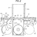
トレイ22の駆動部23Aを内蔵しているハウジングに加えて、このハウジングの下方に、従来式のディスクレコーダである焼付器40が配備されている。レコーダ操作システムも、制御器19により制御される。レコーダ40は、米国特許第6、327、230号に記載のものと同じ形態で構わない。このレコーダは、レコーダハウジングから図1で示す位置まで伸びるCDつまりディスクの支持トレイ42を備えており、制御器19によりレコーダの内部駆動部を制御して、未記録ディスクを導入することができる。レコーダのディスク支持トレイ42の導入位置は、プリンタ側のディスク支持トレイ22の位置の真下、言い換えれば、その位置と整列する位置である。プリンタのトレイ22がハウジング17内に引き込まれると、レコーダトレイ42は、アーム28上のピッカー24から未記録ディスクを受け取ることができる位置にくる。記録動作中は、プリンタのトレイ22はハウジング23内に引込まれたままである。
In addition to the housing in which the
未記録ディスク25が一旦支持トレイ42上に載置されてピッカー24から開放されると、支持トレイ42はレコーダである焼付器のハウジング40内に引き込まれる。その引き込み動作や記録動作も、ユーザの選定した入力信号と共に、制御器19により制御される。記録動作の手順は、レコーダ製造業者が提供するレコーダ動作プログラムにより実行されるが、記録動作の詳細は本発明に関与するものではない。
Once the
記録動作が完了すると、ディスク支持トレイ42は図1に示す位置まで戻されるが、プリンタのトレイ22は引込まれたままである。記録済みのディスクはピッカー24でつかみ上げられ、アーム28の上昇によりディスクは支持トレイ22から離脱できる充分な高さまで持ち上げられる。支持トレイ22はハウジングから外へ延長され(支持トレイ42はその位置に留まっている)、アーム28が下降し、ピッカー24が記録された直後のディスクを支持ディスク22上に載置する。そして、ディスクレベルの印刷が行われる。
When the recording operation is completed, the
印刷動作中は、キャリッジ30を、(印刷ヘッドにより左方向へ押し込まれて)図1で示すその停止位置つまりホームポジションまで戻して、アーム28を駆動してフランジ端31Fを持ち上げフランジ片29Tと係合させてラッチレバー29を持ち上げて、キャリッジ30と印刷ヘッドとの連結を開放しておくのが好ましい。その場合のアーム28の垂直位置は、ディスクの横方向への移動におけるアーム位置よりも高い位置である。その位置は、位置センサ60(図8を参照)により検知できる。
During the printing operation, the
印刷ヘッド16は、制御器19の駆動制御で駆動モータ20とベルト18により、通常の方法で、ベアリング支持軸14とガイドレール12Aに沿って前後に移動されるが、ディスク支持トレイ22は、トレイ駆動部の制御によりガイド軸14に直交して移動する。
The
印刷動作が完了すると、印刷ヘッド16は図1の左方向へと移動され、再びキャリッジ30とのラッチ連結を行う。突起部34が端面29Eをスライドして、ラッチレバー29を持ち上げる。そして、ラッチレバー29のフック29Bが印刷ヘッド16のラグ片つまり係合部34と係合すると、キャリッジ30が移動して、(記録および印刷)処理完了したディスク25をつかみ上げ、図1と図5に示す、装置10の右端にある格納トレイ50まで、あるいは、図9で示す中央の格納位置まで移動させる。
When the printing operation is completed, the
キャリッジ30の印刷ヘッド16へのラッチ連結は、既存部品の効果的な利用により、新規な組み合わせを実現する。ディスク操作用グリッパ24のキャリッジ30は、好ましくは印刷ヘッド16と同じベアリング支持軸14、および、フレーム12の別のガイド部(離れた、つまり平行なガイドであってもよい)に取り付けられており、既存のモータと駆動装置による印刷ヘッド16の駆動により移動できる。ラッチレバー29は、ラッチの下側へ印刷ヘッドをスライド移動させることにより、あるいは、印刷ヘッドをラッチレバー下方へ移動させるより前にアーム28で係合レバーを持ち上げることにより、印刷ヘッドに自動的にラッチ係合できる。
The latch connection of the
続いて、所定の手順を、必要に応じて繰り返す。本実施例では、多くのコピー装置に装備されている枢支タワー部の必要がなく、ディスク搬送機構用の分離独立した駆動装置も必要ない。 Subsequently, the predetermined procedure is repeated as necessary. In the present embodiment, there is no need for a pivot tower provided in many copying apparatuses, and there is no need for a separate and independent drive device for the disk transport mechanism.
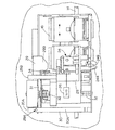
図9に、本発明の別の実施例のCDレコーダ/100を示す。本発明のこの実施例では、印刷ヘッドとキャリッジのラッチ連結機構は前出の実施例と同じであり、図9に示す追加の詳細構成において、ディスクの記録や印刷の処理方法も前記説明と同様である。この実施例では、フレーム12を所定位置に保持するための作業面や作業台などの支持台102が設けられている。フレーム12は、適当な方法でモータで駆動される駆動ベルト18により、その上を印刷ヘッド16が移動できるベアリング支持軸14を備える。本発明のこの実施例におけるプリンタも、前出の実施例のものと同じであって、キャリッジ30を含むディスク搬送機構30Aもラッチレバー29を使用して印刷ヘッド16と相対的に動作制御される。ピッカー24も前のものと同様に動作し、ステッパモータ33を駆動してアーム28とピッカー24を、垂直方向に移動する。
FIG. 9 shows a CD recorder / 100 according to another embodiment of the present invention. In this embodiment of the present invention, the print head and carriage latch coupling mechanism is the same as in the previous embodiment, and in the additional detailed configuration shown in FIG. 9, the recording and printing processing method of the disc is the same as described above. It is. In this embodiment, a support table 102 such as a work surface or a work table for holding the
記録や印刷の動作プログラムも前出のものと同じであるが、本発明におけるこの実施例で違う点は、CDレコーダ/装置の格納容量が、未記録ディスク格納部としてフレーム12上に2つのディスク格納領域つまりホッパを設けることにより増加している点である。図9に示されているように、左側に設置された未記録ディスク格納部104は、前出の未記録ディスクの山を格納する格納部と同様に、ディスクの山を保持するガイド壁部を備える。図から判るように、未記録ディスクの山106が格納領域つまりホッパ104内に格納されている。符号108で示す第2の未記録ディスク格納領域つまりホッパは、他の未記録ディスクの山106を収容できるガイド部で構成されている。格納領域108の位置は、本発明の前出の実施例での処理完了ディスクの格納領域と同じ位置である。
The recording and printing operation programs are the same as those described above, but the difference in this embodiment of the present invention is that the storage capacity of the CD recorder / device is two discs on the
未記録ディスクと同じ数量の記録および印刷完了ディスクを格納するための処理完了ディスク格納領域つまりホッパ110が、フレーム12の中央に配置されており、基本的にプリンタおよびレコーダの二分された面の中央に整列する。支持部つまりホッパ110は、フレーム12の底面まで、あるいは、直接にテーブル台面102まで達する垂直支持壁112を備えており、該支持壁はプリンタ20とレコーダつまり焼付器40のディスク支持トレイとに整列設置された傾斜シュート114に整列配置されている。傾斜シュート114は、レコーダつまり焼付器40のディスク支持トレイ42の下方に隣接した上側位置から下方へ、ガイドフランジ部118を備えた外側トラフ116まで伸びており、その処理完了したディスクがシュートつまり斜面を下降する際に処理完了ディスク120をガイドする役目をする。シュートつまり斜面114の上端が、アーム28とグリッパ24の外側端の下側に位置しているので、アーム28とグリッパ24がディスクトレイ22から処理完了ディスクを持ち上げて取り除くのに使われたとき、モータ33を駆動してアーム28を所定距離だけ下降して、その処理完了ディスク120を下方へ移動させ、斜面114へ落として、図の矢印で示すように、支持領域つまりホッパ110のガイド部124の中間までスライド下降させることができる。ガイド部124は、図示のように部分円弧形状であり、垂直壁112に取り付けられた支持部110の水平ベース部材126の上に支持されている。
A processing completion disk storage area or
ガイド部124は部分円弧であり、両方の格納部104と108内の未記録ディスク106と同じ数量の処理完了ディスクを収容できるよう構成されている。例えば、格納部104と108のそれぞれに25枚の未記録ディスクが格納される場合、支持部つまりホッパ110は50枚の処理完了ディスクを収容できる。
The
それゆえ、本実施例のディスクのレコーダ/プリンタは、コンパクトなサイズとなる。処理完了ディスク支持部110は、フレーム12を作業面つまり作業台102に配置した後で配備することもできる。
Therefore, the disk recorder / printer of this embodiment has a compact size. The processing completion
処理完了ディスク支持部110の中央を二分する面は、ガイド軸14に直交しており、処理が完了しグリッパ24から開放されたディスク120がスライド下降する中心線を規定している。前記面は、印刷動作中や記録動作中にディスクを支持する両ディスク支持トレイ22と42とに二分される。そのため、処理完了後のディスク支持部110は、プリンタの二分面の中央に配置される。未記録ディスク格納領域つまりホッパ104と108もこの面の両側に基本的に同じ距離で配置されているので、アーム28による、最初に記録用支持トレイに載置し、次に印刷用トレイに載置するための未記録ディスクをつかみ上げる操作が簡単にできる。
A surface that bisects the center of the processing
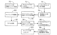
図10に示すのは、本発明による処理動作のブロック図である。70で示すブロックは、処理の開始である。印刷動作以外のときには、キャリッジ30は印刷ヘッド16にラッチ連結されているため、キャリッジ30の位置が認識されて制御される。ブロック72では、キャリッジ30の「ピッカー」24を使って、未記録ディスクがつまみ上げられる。
FIG. 10 is a block diagram of processing operations according to the present invention. The block indicated by 70 is the start of processing. During a time other than the printing operation, the
次のブロック74では、印刷ヘッド16が駆動され、それにつれてキャリッジ30が移動して未記録ディスクをCDレコーダ側のトレイまで搬送する。CD(あるいは別の記録可能ディスク)の記録や焼付は、レコーダハウジング内で行われる。ブロック76では、キャリッジ30がレコーダ側トレイまで移動され、グリッパ24により記録済みCDが取り外された後、レコーダ側トレイを後退させる。続いて、ブロック78では、プリンタ側トレイ22が引き出されて、そのプリンタ側トレイ上にCDが載置される。ブロック80では、キャリッジ30が印刷ヘッドから開放されて、その格納位置まで移動される。そして、インクジェット式印刷ヘッドにより、ラベル情報が印刷される。この動作は、ブロック82に示す。印刷終了後、ブロック84で示すように、キャリッジ30を再び印刷ヘッド16とラッチ連結させ、次のブロック86で示すように、「ピッカー」つまりグリッパ24を使って処理完了したディスクをプリンタ側トレイからつかみ上げて、ブロック88で示すように処理完了したCDを、格納場所50あるいは支持部110の完了ディスクの山まで移動させる。
In the
ブロック90で示すように、キャリッジ30をリセットするため、左方向へ移動させて、印刷ヘッドとラッチ連結する。続いて、別のサイクルの記録と印刷のプログラムを実行する場合、新規の未記録ディスクまたはCDを格納領域から取り出して同様の手順を繰り返す。
As indicated by
印刷ヘッドの駆動部を使って、未記録ディスク格納部、印刷および記録部、処理完了ディスク格納部の間でCDを搬送するキャリッジ30の能力により、迅速で簡単な制御動作を実行できるだけでなく、CD搬送部やピックアーム部の複雑な機構や必要コストを低減することができる。
The ability of the
図11から図14に図示するのは、本発明の第1の実施例で説明した搬送機構38、キャリッジ30、アーム28の変形例である。
FIG. 11 to FIG. 14 show modified examples of the transport mechanism 38, the
図11に示す変形例において、符号150で示すプリンタは、本発明の第1の実施例で説明した標準プリンタであって、例えば、米国ケンタッキー州レキシントン(Lexington, KY)のレックスマーク インターナショナル インコーポレイテッド(Lexmark International, Inc.)が製造販売するプリンタである。プリンタには、印刷ヘッド156がスライド移動可能に搭載された横方向ベアリング支持軸154を備えた標準式フレーム152が設けられている。図示の印刷ヘッド156はツイン式であって、これらの印刷ヘッドはフレーム152の上側のトラック152Aに沿って、上述したように案内できるようになっている。印刷ヘッド156は2個のインクカートリッジを備えており、図11ではそのうちの1個は断片が図示されている。インクカートリッジ156Aは、前に説明したのと同じである。インクカートリッジ156Aは、前の実施例で説明したように、一般的なインクジェット印刷ヘッドで利用される従来の駆動機構であるモータ駆動の駆動ベルト158により動作する。ベルト158を介する駆動部は、印刷ヘッド156を支持軸154に沿って移動させ、上述したようにプリンタの動きに同期する。CDプリンタハウジング153がプリンタフレーム152の中央部に取り付けられており、前に説明したように、図示のディスク165などのディスク上面印刷動作のため内外に移動可能なトレイを備えている。ディスクプリンタやCD焼付器の動作は、前に説明した動作とまさに同じである。
In the modification shown in FIG. 11, the printer denoted by
しかしながらこの変形例では、ディスク搬送機構169が変形されており、ピッカーアーム168を搭載する枢支可能なアームキャリッジ集合体170を備える。アームキャリッジ集合体170は、搬送機能169のフレーム169Aに、フレームに対して枢支可能に取り付けられている。そして、アーム168には前に説明したように、グリッパ164が備わっており、CDやDVDなどのディスク165を上下移動させることができる。ピッカーの動作も、前に説明したとおりである。アーム168はキャリッジ170に取り付けられており、キャリッジ170は印刷ヘッド156と同じベアリング支持軸164にスライド移動可能に取り付けられているが、必要に応じて、移動安定性のためフレーム端152Aでガイドしても構わない。
However, in this modification, the
搬送機構169は、ラッチレバー29に関して説明したように動作するラッチレバー173を使用することにより、ベアリング支持軸154に沿った移動が可能となっている。ラッチレバー173は、プリンタフレーム156の突起部つまり係合部173Aにラッチ連結できるため、ディスク搬送機構169とアーム168が、図11に実線で示す位置と図11の点線で示す位置との間を移動できる。
The
アームキャリッジ170は、図13と図14に詳細に図示されており、本発明の変形例では中央ブロック171に、垂直ネジ棒つまりネジ支柱172にネジ込み取り付けされたネジ付き中央ハブ171Cが備わっている。ネジ棒つまりネジ支柱172は、キャリッジ170に回転可能に支持されている。キャリッジ170は、共に側面ガイド支持ロッド178上に設けられた底面板174と上面板176を備える。それらガイド支持ロッド178は互いに距離をおいて設置されており、ガイド支持ロッドの片方端が適当なネジ部材で上下面板に取り付けられているため、上下面板174および176と共に移動できる。中央ブロック171には、ロッド178に沿ってガイドするためのU字形状のサドルつまりガイド受容部180が備わっており、ネジ支柱172にはネジ溝があるため、ハブ171Cは上昇下降できる。ネジ支柱172は、ディスク搬送機構169に搭載されたモータ182で回転駆動される。モータ182およびネジ支柱172が中央ハブ171Cに対して回転して、中央ブロック171が上下に移動できる。ガイド支持ロッド178、上下面板174、176、およびアーム168は、キャリッジ170と共に移動する。それゆえ、キャリッジ170は、ディスク搬送機構169のフレーム169Aに対してネジ172の軸まわりに枢支移動できるように取り付けされている。つまり、キャリッジ170、アーム168は、ネジ支柱172を中心に枢支回転できる。
The
ネジ棒つまりネジ支柱172は、フレーム169Aの底壁186と底面板174とに設けられた適当なブッシュ184に回転可能に挿入されている。なお図から判るように、底面板174は、ディスク搬送機構のフレーム169Aの底壁186から間隔をおいて取り付けられている。そのため、ガイド支柱ロッド178により中央ブロック171の回転が防止されるため、上下面板174や176の枢支位置に影響することなく、ネジ支柱172はモータ182の駆動により回転することができる。
The screw rod or
フレーム169Aとキャリッジ170には、キャリッジを左右の所定位置で固定させるためのバネ付勢係止部材が備わっている。係止部材は周知の部材であり、バネ付勢式の係止ボールでもよいし、その他の形状の係止部材でも構わない。
The
ネジ支柱172の回転動作により、中央ブロック171とそのハブ171Cがネジ支柱に沿って上下移動して、ピッカーが未記録ディスク格納領域188の上方に達するようアーム168を移動させる。未記録ディスク格納領域にはホッパー189が備わっており、アーム168が所定位置に到達した後、グリッパ164を動作させて、未記録ディスク格納ホッパ189から1枚のディスク165をつかみ上げる。
The central block 171 and its hub 171 </ b> C move up and down along the screw column by the rotation operation of the
上下面板174と176、および、それら上下面板174、176、ガイド支持ロッド178と共に枢支回転する中央ブロック171は、アーム168と同様に、ネジ支柱172の軸まわりに回転することができる。図11からも判るように、アーム168には動作レバー200が固定装備されている。動作レバー200は、プリンタフレームから後方向へ伸びて、上側レール152の後部にまたがっている。上側レール152には、上方へ突出した第1停止突起部202が固定取り付けされている。キャリッジ170を含むディスク搬送機構169が、図11の左端の印刷ヘッド146の移動終点の位置に達すると、動作レバー200が突起部202に衝突する。そして、キャリッジ170がネジ支柱170の軸まわりに回転して図の実線で示す位置に到達するが、同時に、アーム168が中央位置から時計まわりに枢支回転する。図11から判るように、下面板174の一方の端は外側に傾斜しており(上面板176も枢支移動する)、アーム168とピッカー164は、上側レール152と直交する線よりも遠くまで図11の左側へ移動することになる。ラッチ173が印刷ヘッド156の係合部173Aと係合し、かつ、印刷ヘッド156が図11の右方向へずっと移動すると、動作レバー200は第2停止突起部204に衝突し、キャリッジ170は反時計まわりに枢支回転する。そして、上下面板174と176、ガイド178、アーム168も、図11の点線で示す位置まで反時計まわりに枢支回転する。その結果、ピッカーは、本発明の前出の実施例で説明したのと同じようなCD記録焼付器212にて印刷焼付されたディスク210の処理完了ディスク格納領域208の上方に到達する。
The upper and
さらに、キャリッジ170は、前記左右位置にてそれぞれの突起部202と204との係合にて枢支回転した後で、その位置で停止することができる。停止動作は、キャリッジ170の下面部174とフレーム169Aの底壁186の間で作用する。
Further, the
それゆえ、アーム168が垂直軸まわりに枢支回転することにより、印刷ヘッドやキャリッジで許容されたアーム168の移動距離よりも遠くまで移動できる。図11の点線で示すアーム168に対して、印刷ヘッドの移動は、フレーム152の側面までであり、それ以上に右方向へ移動することはできない。
Therefore, when the
図14に、ネジ支柱172のブッシュ184、および、ガイド支柱178へのプレート174の固定形態をより詳細に示す。動作レバー200が両突起部202と204のいずれかに衝突すると、上下面板174と176およびガイド支柱178は一体に枢支回転する。
FIG. 14 shows in more detail how the
ここで、CDをCD記録焼付位置や印刷位置に搬送するときには、アーム168が図11の実線で示す位置に保持されることに注目してほしい。印刷ヘッドの位置は、アームの位置を決定するためプログラムすることができる。
Here, it should be noted that when the CD is transported to the CD recording printing position or the printing position, the
前記駆動部によりアームを垂直方向に上下移動させるため垂直軸まわりの枢支回転できる能力以外は、図11から図14に図示されたプリンタやCD焼付レコーダの動作は前出の実施例で説明したものと同じである。 The operations of the printer and the CD printing recorder shown in FIGS. 11 to 14 have been described in the previous embodiment except for the capability of pivoting around the vertical axis to move the arm up and down in the vertical direction by the drive unit. Is the same.
同様に、使用するディスクのサイズ形状も、ビジネスカードディスク、IDディスク、ミニディスクなど所望ディスクから自在に選定できる。また、ピッカーも、取り扱うディスクに見合った構成にすることができる。 Similarly, the size and shape of the disk to be used can be freely selected from desired disks such as a business card disk, ID disk, and mini disk. Also, the picker can be configured to match the disc being handled.
キャリッジ30や170は、印刷ヘッドの移動に平行したキャリッジ移動を印刷ヘッドに行わせるような別途設置のベアリング支持軸やガイドレールに取り付けることも可能である。そのような平行スライド移動のための追加部材はコストアップにつながるかもしれないが、利用可能である。
The
本発明は好ましい実施例に基づいて説明したが、本発明の精神や範囲を逸脱することなく詳細部分の変更が可能なのも当業者には理解できよう。 While the invention has been described with reference to preferred embodiments, those skilled in the art will recognize that changes may be made in detail without departing from the spirit or scope of the invention.
10……ディスクのプリンタ/レコーダ焼付装置、
12……フレーム、
12A……トラック、
13……端部支持体、
14……ベアリング支持軸、
15……ベースプレート、
16……印刷ヘッド、
16A,16B……インクカートリッジ、
18……駆動ベルト、
19……中央制御器、
20……モータ、
22……ディスク支持トレイ、
23……CDプリンタハウジング、
24……ピッカー、
24B……垂直フィンガーブレード、
25A……ディスク(CD)、
26……ソレノイド、
28……アーム、
29……ラッチレバー、
29B……キャッチ(フック)、
30……キャリッジ、
30A……ディスク搬送機構、
31……中央ブロック
32……垂直ネジ棒(支柱)、
33……ステップモータ、
34……係合部、
35A,35B……垂直ガイド支持壁部、
40……焼付器、
42……レコーダトレイ
10: Disc printer / recorder printing device,
12 …… Frame,
12A …… Track,
13 …… End support,
14: Bearing support shaft,
15 …… Base plate,
16 …… Print head,
16A, 16B ... ink cartridge,
18 …… Drive belt,
19 …… Central controller,
20 …… Motor,
22: Disc support tray,
23 …… CD printer housing,
24 …… Picker,
24B ...... Vertical finger blade,
25A: Disc (CD),
26 …… Solenoid,
28 …… Arm,
29 …… Latch lever,
29B …… Catch (hook),
30 ... carriage,
30A: Disc transport mechanism,
31 ……
33 …… Step motor,
34 ...... engagement part,
35A, 35B ... vertical guide support wall,
40 ... Baking device,
42 …… Recorder tray
Claims (7)
前記処理ディスク支持体に対して交差方向に延びるガイドを備え、前記ディスク処理部および前記処理ディスク支持体を支持するフレームと、
前記ガイドに取り付けられており、前記処理ディスク支持体内のディスクを処理するために、前記ガイドに沿って移動可能に制御される処理部材と、
ディスクグリッパを有するディスクピックアップヘッドを含んでおり、前記処理ディスク支持体と交差して動くように前記フレームに固定され、前記処理部材が格納領域から前記処理ディスク支持体へ前記ガイドに沿って移動するのにつれて、ディスクを移動するために前記処理部材と共に移動するように前記移動可能な処理部材に結合可能であるディスク搬送機構とからなるプラスチック製ディスクを選択的に処理するためのディスク処理装置。A disk processing section with a processing disk support that is movable between a loading position and a processing position and that can be extended and retracted to receive a processing disk;
A guide extending in a crossing direction with respect to the processing disk support, and a frame for supporting the disk processing unit and the processing disk support;
A processing member attached to the guide and controlled to be movable along the guide to process a disk in the processing disk support;
A disk pick-up head having a disk gripper, fixed to the frame so as to move across the processing disk support, and the processing member moving from the storage area to the processing disk support along the guide; Accordingly, a disk processing apparatus for selectively processing a plastic disk comprising a disk transport mechanism that can be coupled to the movable processing member to move with the processing member to move the disk.
記録用ディスクを受容して供給するための拡張可能な第2のディスク支持体を備えており、該第2のディスク支持体は装荷位置まで延びており、前記ディスク搬送機構が、前記処理ディスク支持体および前記第2のディスク支持体上に選択的にディスクを載置するために前記印刷ヘッドと共に移動可能であるディスクレコーダを備えた請求項1のディスク処理装置。Further, a disk printer constituting a disk processing unit including a print head that can be controlled to move the processing member along the guide;
An expandable second disk support for receiving and supplying a recording disk, the second disk support extending to a loading position, wherein the disk transport mechanism includes the processing disk support; 2. A disk processing apparatus according to claim 1, further comprising a disk recorder movable with said print head to selectively place a disk on the body and said second disk support.
前記ガイドに平行な方向で前記フレーム上の第1位置と第2位置の間を移動できるピッカーアーム支持体と、
前記ピッカーアーム支持体上に垂直軸まわりに枢支可能に取り付けられたキャリッジと、
前記キャリッジ上に取り付けられたピッカーアームであって、前記ピッカーアーム支持体が前記第1位置まで第1方向へ移動するときは、第1回転方向に前記アームを枢支回転させるよう前記フレームに取り付けられた第2部材と係合する第1部材を備え、かつ、前記ピッカーアーム支持体が前記第2位置まで第2方向へ移動するときは、第1回転方向とは逆の第2回転方向に前記ピッカーアームを枢支回転させるよう前記フレームに取り付けられた第3部材と第1部材が係合するピッカーアームとからなる請求項1記載のディスク処理装置。 The processing disk support is
A picker arm support capable of moving between a first position and a second position on the frame in a direction parallel to the guide ;
A carriage mounted pivotably about a vertical axis on the picker arm support;
A picker arm mounted on the carriage, wherein the picker arm support is attached to the frame to pivotally rotate the arm in a first rotational direction when the picker arm support moves in the first direction to the first position ; A first member that engages with the second member, and when the picker arm support moves in the second direction to the second position , the second rotation direction is opposite to the first rotation direction. disc processing apparatus according to claim 1, wherein the third member and the first member attached to said frame so as to pivotally rotate the picker arm is made of a picker arm that engages.
前記ディスク搬送機構は、前記処理ディスク支持体から処理されたディスクを取り外して前記傾斜斜面上に載置することにより、該処理されたディスクを、前記ディスク処理部からスライド離脱させるように操作可能である請求項1記載のディスク処理装置。When the process disk support is in loading position, under the process disk support, is arranged in the process disk support extends in a direction away from the disc processor, away from the disc processor Having an inclined slope inclined downward in the direction,
The disk transport mechanism is operable to detach the processed disk from the processing disk support and place it on the inclined slope so that the processed disk is slid away from the disk processing unit. The disk processing apparatus according to claim 1 .
Applications Claiming Priority (2)
| Application Number | Priority Date | Filing Date | Title |
|---|---|---|---|
| US10/162,363 US6760052B2 (en) | 2002-06-03 | 2002-06-03 | CD recorder and printer |
| PCT/US2003/016846 WO2003102944A2 (en) | 2002-06-03 | 2003-05-29 | Cd recorder and printer |
Publications (3)
| Publication Number | Publication Date |
|---|---|
| JP2005528729A JP2005528729A (en) | 2005-09-22 |
| JP2005528729A5 JP2005528729A5 (en) | 2006-07-20 |
| JP4555680B2 true JP4555680B2 (en) | 2010-10-06 |
Family
ID=29583592
Family Applications (1)
| Application Number | Title | Priority Date | Filing Date |
|---|---|---|---|
| JP2004509943A Expired - Fee Related JP4555680B2 (en) | 2002-06-03 | 2003-05-29 | CD recorder / printer device |
Country Status (9)
| Country | Link |
|---|---|
| US (4) | US6760052B2 (en) |
| EP (1) | EP1565912B1 (en) |
| JP (1) | JP4555680B2 (en) |
| KR (1) | KR100978595B1 (en) |
| CN (1) | CN100389466C (en) |
| AT (1) | ATE504061T1 (en) |
| AU (1) | AU2003245350A1 (en) |
| DE (1) | DE60336579D1 (en) |
| WO (1) | WO2003102944A2 (en) |
Families Citing this family (78)
| Publication number | Priority date | Publication date | Assignee | Title |
|---|---|---|---|---|
| US7032232B2 (en) * | 1998-06-01 | 2006-04-18 | Microboards Technology, Llc | Memory storage disk handling system |
| US6337842B1 (en) | 1998-06-01 | 2002-01-08 | Microboards Technology, L.L.C. | Disk handling system having a telescoping elevator pin |
| US6990674B1 (en) * | 2001-08-08 | 2006-01-24 | Primera Technology, Inc. | Picker support for disc duplicator |
| JP3906114B2 (en) * | 2002-06-10 | 2007-04-18 | 富士通テン株式会社 | Disc player |
| JP3780232B2 (en) * | 2002-07-10 | 2006-05-31 | キヤノン株式会社 | Recording device |
| JP4027185B2 (en) * | 2002-08-30 | 2007-12-26 | キヤノン株式会社 | Recording device |
| US7127725B2 (en) * | 2002-09-25 | 2006-10-24 | Rimage Corporation | Disc collator |
| US7063746B2 (en) * | 2002-10-15 | 2006-06-20 | Microbroads Technology, Llc | In-line marking system |
| US7150790B2 (en) * | 2002-10-15 | 2006-12-19 | Microboards Technology, Llc | In-line marking system |
| US7390362B2 (en) * | 2002-10-15 | 2008-06-24 | Microboards Llc | Thermal printer |
| US7036131B2 (en) * | 2003-03-05 | 2006-04-25 | Hewlett-Packard Development Company, L.P. | Printing optical disc player/recorder |
| JP4222070B2 (en) * | 2003-03-11 | 2009-02-12 | ブラザー工業株式会社 | Fabric printing device |
| US7426055B2 (en) * | 2003-08-26 | 2008-09-16 | Leason Holdings Company, L.L.C. | Optical disc supply and interface for digital copier machine |
| US20050100434A1 (en) * | 2003-10-14 | 2005-05-12 | Zoltan Filep | Multiple-picker system for media handling and other equipment |
| US7349294B2 (en) * | 2004-01-20 | 2008-03-25 | Primera Technology Inc. | Disc error checking sensor for printers and duplicators |
| US7254818B2 (en) * | 2004-01-20 | 2007-08-07 | Primera Technology, Inc. | Self aligning disc tray drive |
| ES2259867B1 (en) * | 2004-02-04 | 2007-10-01 | Ludicus Contest, S.L. | PLAYER MACHINE AND ISSUER OF DIGITAL FILES. |
| TWI269277B (en) * | 2004-03-08 | 2006-12-21 | Ming-Shiun Liou | Disc copying system and disc conveying method |
| US7555758B2 (en) | 2004-03-08 | 2009-06-30 | Ming-Hsun Liu | Transportation device and compact disc processing system using the same |
| US20050213494A1 (en) * | 2004-03-09 | 2005-09-29 | Nelson Westin W | Output bin |
| US20080288969A1 (en) * | 2004-04-01 | 2008-11-20 | Victor Waiman | Unattended Data Storage System |
| US7150573B2 (en) * | 2004-09-10 | 2006-12-19 | Primera Technology, Inc. | Label printer with label supply feed control |
| US7653447B2 (en) * | 2004-12-30 | 2010-01-26 | Mondo Systems, Inc. | Integrated audio video signal processing system using centralized processing of signals |
| US7540237B2 (en) * | 2005-01-19 | 2009-06-02 | Kubin Dale K | Printer |
| JP2006295878A (en) * | 2005-01-25 | 2006-10-26 | Ricoh Co Ltd | Image forming device |
| US20060244989A1 (en) * | 2005-04-13 | 2006-11-02 | Charles Evans | Systems for and methods of presenting digital images |
| US20060232879A1 (en) * | 2005-04-18 | 2006-10-19 | Primera Technology, Inc. | Rack mountable data recording assembly |
| US20060248551A1 (en) * | 2005-04-28 | 2006-11-02 | Taugher Lawrence N | Single motor connected to an optical pick up unit and an optical print head |
| US20070025794A1 (en) * | 2005-06-17 | 2007-02-01 | Kubin Dale K | A printer |
| KR100918654B1 (en) * | 2005-06-20 | 2009-09-22 | 엘지디스플레이 주식회사 | Ink Jet Printing Device |
| US20070070169A1 (en) * | 2005-09-28 | 2007-03-29 | Hanks D M | Laser positioning in an optical disc drive |
| US7650612B2 (en) * | 2005-12-22 | 2010-01-19 | Datatronics Technology, Inc. | Transportation arm device for carrying discs |
| TW200823872A (en) * | 2006-11-24 | 2008-06-01 | Datatronics Technology Inc | Auto feed, copy and print apparatus for compact disks and method of the same |
| JP4367428B2 (en) * | 2006-04-07 | 2009-11-18 | ソニー株式会社 | Recording medium processing apparatus, printing method, and computer program |
| JP2007310920A (en) * | 2006-05-16 | 2007-11-29 | Seiko Epson Corp | Gripping mechanism of disk |
| JP4997823B2 (en) * | 2006-05-16 | 2012-08-08 | セイコーエプソン株式会社 | Disc gripping mechanism |
| US8049768B2 (en) * | 2006-08-09 | 2011-11-01 | Primera Technology, Inc. | Disc output storage drawer for processor |
| US7810109B2 (en) * | 2006-08-09 | 2010-10-05 | Primera Technology Inc. | Compact disc picker |
| KR100762358B1 (en) * | 2006-09-29 | 2007-10-02 | 도시바삼성스토리지테크놀러지코리아 주식회사 | Optical recording/reproducing apparatus capable of label printing |
| JP2008097731A (en) * | 2006-10-12 | 2008-04-24 | Sony Corp | Recording medium changer |
| JP4650950B2 (en) * | 2006-10-17 | 2011-03-16 | 株式会社リコー | Disk transport device and disk device |
| JP2008135148A (en) * | 2006-10-23 | 2008-06-12 | Seiko Epson Corp | Media processor |
| CN101192429B (en) * | 2006-11-24 | 2010-09-01 | 刘明勋 | Automatic disc-feeding read-write printing device suitable for optically readable-writable disc and its method |
| JP4848946B2 (en) * | 2006-12-07 | 2011-12-28 | セイコーエプソン株式会社 | Printer and media processing apparatus |
| US20080229342A1 (en) * | 2007-03-16 | 2008-09-18 | Kubin Dale K | Method for picking and placing a disc |
| US20080256565A1 (en) * | 2007-03-16 | 2008-10-16 | Xlnt Idea, Inc. | Disc transport and method of disc removal |
| US20080229341A1 (en) * | 2007-03-16 | 2008-09-18 | Kubin Dale K | Disc transport with an improved disc engagement mechanism |
| US7874786B2 (en) * | 2007-03-19 | 2011-01-25 | Ming-Hsun Liu | Disc turning chute and method thereof |
| US20080244627A1 (en) * | 2007-03-26 | 2008-10-02 | Kubin Dale K | Disc transport with carousel |
| US20080267018A1 (en) * | 2007-04-03 | 2008-10-30 | Xlnt Idea, Inc. | Disc transport auto-calibration |
| JP4375425B2 (en) * | 2007-04-05 | 2009-12-02 | セイコーエプソン株式会社 | Media transport mechanism, media processing apparatus including the same, and media transport method |
| US7929384B2 (en) * | 2007-04-06 | 2011-04-19 | Ming-Hsun Liu | Multi-stage disk-feeding apparatus for information storage disks |
| US20080271064A1 (en) * | 2007-04-26 | 2008-10-30 | Kubin Dale K | Portable integrated disc-publishing device |
| US20090025020A1 (en) * | 2007-07-18 | 2009-01-22 | Kahle Rolf D | Optical disc loader for recorders with integrated labeling facility |
| JP2009040527A (en) | 2007-08-06 | 2009-02-26 | Seiko Epson Corp | Tray |
| JP5119823B2 (en) * | 2007-09-19 | 2013-01-16 | セイコーエプソン株式会社 | Information transmission system for electronic equipment, media processing device, and control method for media processing device |
| US20090193446A1 (en) * | 2008-01-29 | 2009-07-30 | Raptor Innovations International, Inc. | Apparatuses for Transportation of Disc in Connection with Recording Data and Apparatus for Such Recording |
| JP2009277340A (en) * | 2008-04-18 | 2009-11-26 | Seiko Epson Corp | Disk conveyance mechanism of disk processing apparatus, and disk processing apparatus |
| JP5309678B2 (en) * | 2008-05-07 | 2013-10-09 | セイコーエプソン株式会社 | Disk processing apparatus and disk processing apparatus control method |
| JP4752869B2 (en) * | 2008-05-29 | 2011-08-17 | ソニー株式会社 | Head moving mechanism and image forming apparatus |
| US7779432B2 (en) * | 2008-07-29 | 2010-08-17 | Datatronics Technology, Inc. | Automatic disk feeding device for disk duplication system and method thereof |
| JP5309790B2 (en) * | 2008-08-26 | 2013-10-09 | セイコーエプソン株式会社 | Route mechanism and information processing apparatus having the same |
| CN101683929B (en) * | 2008-09-24 | 2011-06-29 | 建茂科技企业有限公司 | Compact disk printing driving device |
| CN101722740B (en) * | 2008-10-21 | 2012-01-04 | 研能科技股份有限公司 | Portable disc label printing device |
| JP5604790B2 (en) | 2009-02-04 | 2014-10-15 | セイコーエプソン株式会社 | Printing method and printing apparatus |
| JP2011003255A (en) * | 2009-06-22 | 2011-01-06 | Alps Electric Co Ltd | Label printer |
| TWM398178U (en) * | 2010-06-15 | 2011-02-11 | Acard Technology Corp | recording device |
| CN102259507A (en) * | 2011-06-16 | 2011-11-30 | 苏州万图明电子软件有限公司 | Printer with telescopic paper holder |
| US8585115B2 (en) * | 2011-10-07 | 2013-11-19 | Varian Semiconductor Equipment Associates, Inc. | Method and apparatus for lifting a horizontally-oriented substrate from a cassette |
| JP5833420B2 (en) * | 2011-12-15 | 2015-12-16 | 日本電産サンキョー株式会社 | Media processing device |
| CN105517806B (en) * | 2013-08-30 | 2018-06-12 | 普利麦罗技术公司 | Box printer with picker |
| DE102014004365B4 (en) * | 2014-03-26 | 2016-11-03 | Phoenix Contact Gmbh & Co. Kg | marking device |
| JP7154864B2 (en) * | 2018-08-01 | 2022-10-18 | キヤノン株式会社 | Recording device and recording method |
| US10546608B1 (en) * | 2019-02-04 | 2020-01-28 | International Business Machines Corporation | Method and system for selecting and moving a single disc in an optical disc library |
| JP2020187807A (en) * | 2019-05-13 | 2020-11-19 | セイコーエプソン株式会社 | Recording medium processing device |
| CN112277463B (en) * | 2019-07-22 | 2021-05-28 | 苏州互盟信息存储技术有限公司 | Printer trolley, optical disk printer and optical disk burning and printing all-in-one machine |
| CN112259131B (en) * | 2019-07-22 | 2021-12-10 | 苏州互盟信息存储技术有限公司 | CD burning and printing integrated machine |
| CN110667261B (en) * | 2019-10-25 | 2020-08-04 | 北京万盘科技有限公司 | Optical disk printing device and printer |
Family Cites Families (32)
| Publication number | Priority date | Publication date | Assignee | Title |
|---|---|---|---|---|
| FR2711125B1 (en) | 1993-10-13 | 1996-01-26 | Dubuit Mach | Charger for printing machine for objects presented in stack. |
| US5509191A (en) * | 1994-01-26 | 1996-04-23 | Best; Norman D. | Apparatus for assembling and processing small parts using a robot |
| US5518325A (en) | 1994-02-28 | 1996-05-21 | Compulog | Disk label printing |
| US5542768A (en) | 1995-02-03 | 1996-08-06 | Rimage Corporation | Apparatus for printing on plastic disk |
| DE69618553T2 (en) * | 1995-06-29 | 2002-09-26 | Eastman Kodak Co | METHOD AND DEVICE FOR PRODUCING LABELED NUMERIC PLATES |
| JP3126302B2 (en) | 1995-09-29 | 2001-01-22 | 株式会社マスターマインド | Printing device for plate-shaped recording media |
| US5734629A (en) | 1995-12-28 | 1998-03-31 | Rimage Corporation | CD transporter |
| JPH1064224A (en) * | 1996-08-26 | 1998-03-06 | Sony Corp | Removable disk cartridge |
| US5946216A (en) | 1996-11-14 | 1999-08-31 | Cedar Technologies, Inc. | Vertical transport device for recording and verifying plastic disks |
| US5873692A (en) | 1996-11-15 | 1999-02-23 | Costas; Dan N. | CD picker |
| US6141298A (en) | 1997-03-13 | 2000-10-31 | Miller; David | Programmable self-operating compact disk duplication system |
| JPH10264356A (en) * | 1997-03-26 | 1998-10-06 | Nippon Bunka Seiko Kk | Conveyor type multicolor printer for disk |
| US6222800B1 (en) | 1997-06-02 | 2001-04-24 | Copy Pro, Inc. | Autoload disk copier system |
| US5934865A (en) | 1997-11-25 | 1999-08-10 | Trace Digital Llc | Disk gripper |
| US6270176B1 (en) | 1997-12-11 | 2001-08-07 | Compulog Corporation | Method and apparatus for printing labels on digital recording media |
| JPH11180012A (en) * | 1997-12-19 | 1999-07-06 | Canon Inc | Image recording apparatus |
| US5927208A (en) | 1997-12-31 | 1999-07-27 | Primera Technology, Inc. | CD printer centering adjustment |
| US6111847A (en) | 1998-01-16 | 2000-08-29 | Assadian; Hamid R. | Picker device and method for handling planar objects having an aperture therein |
| US6910750B2 (en) * | 2000-06-02 | 2005-06-28 | Elesys, Inc. | Low-profile ink head cartridge with integrated movement mechanism and service station |
| US7032232B2 (en) * | 1998-06-01 | 2006-04-18 | Microboards Technology, Llc | Memory storage disk handling system |
| US6148722A (en) | 1998-06-08 | 2000-11-21 | Primera Technology, Inc. | Compact disc and recordable compact disc thermal transfer printer |
| US6302601B1 (en) | 1998-06-08 | 2001-10-16 | Primera Technology, Inc. | Substrate carrier and printhead mounting for printer |
| US6447181B1 (en) * | 1998-06-08 | 2002-09-10 | Primera Technology, Inc. | Variable position, force and velocity printer |
| JP3570668B2 (en) * | 1998-12-04 | 2004-09-29 | 株式会社リコー | Optical disk device and optical disk |
| JP3551815B2 (en) | 1999-03-08 | 2004-08-11 | ティアック株式会社 | Disk manufacturing equipment |
| JP3957247B2 (en) * | 1999-05-26 | 2007-08-15 | 株式会社リコー | Label printing system |
| US6327230B1 (en) | 1999-11-04 | 2001-12-04 | Copypro, Inc. | Disk process and transport mechanism for host machines |
| US6321649B1 (en) | 1999-11-12 | 2001-11-27 | Rimage Corporation | Compact disc label printer with rotatable picker arm |
| JP3946438B2 (en) | 2000-01-26 | 2007-07-18 | 有限会社データンク | Disc-shaped storage medium supply device |
| JP2002056584A (en) | 2000-08-08 | 2002-02-22 | Ekisupaato Magnetics Kk | Device for writing and printing of recording medium |
| US6990674B1 (en) * | 2001-08-08 | 2006-01-24 | Primera Technology, Inc. | Picker support for disc duplicator |
| US6580444B1 (en) * | 2002-04-30 | 2003-06-17 | Alexander V. Drynkin | Thermal printer for compact disks and other media |
-
2002
- 2002-06-03 US US10/162,363 patent/US6760052B2/en not_active Expired - Lifetime
-
2003
- 2003-05-29 WO PCT/US2003/016846 patent/WO2003102944A2/en active Search and Examination
- 2003-05-29 AT AT03738989T patent/ATE504061T1/en not_active IP Right Cessation
- 2003-05-29 US US10/447,503 patent/US7061515B2/en not_active Expired - Fee Related
- 2003-05-29 KR KR1020047019571A patent/KR100978595B1/en not_active IP Right Cessation
- 2003-05-29 CN CNB038114054A patent/CN100389466C/en not_active Expired - Lifetime
- 2003-05-29 JP JP2004509943A patent/JP4555680B2/en not_active Expired - Fee Related
- 2003-05-29 DE DE60336579T patent/DE60336579D1/en not_active Expired - Lifetime
- 2003-05-29 EP EP03738989A patent/EP1565912B1/en not_active Expired - Lifetime
- 2003-05-29 AU AU2003245350A patent/AU2003245350A1/en not_active Abandoned
-
2004
- 2004-10-07 US US10/960,199 patent/US7209156B2/en not_active Expired - Fee Related
-
2006
- 2006-01-17 US US11/332,985 patent/US7301550B2/en not_active Expired - Lifetime
Also Published As
| Publication number | Publication date |
|---|---|
| WO2003102944A2 (en) | 2003-12-11 |
| CN100389466C (en) | 2008-05-21 |
| US6760052B2 (en) | 2004-07-06 |
| US20030222928A1 (en) | 2003-12-04 |
| DE60336579D1 (en) | 2011-05-12 |
| US20050069344A1 (en) | 2005-03-31 |
| ATE504061T1 (en) | 2011-04-15 |
| EP1565912A2 (en) | 2005-08-24 |
| EP1565912B1 (en) | 2011-03-30 |
| KR100978595B1 (en) | 2010-08-27 |
| US20060114307A1 (en) | 2006-06-01 |
| JP2005528729A (en) | 2005-09-22 |
| US7301550B2 (en) | 2007-11-27 |
| US7209156B2 (en) | 2007-04-24 |
| AU2003245350A1 (en) | 2003-12-19 |
| CN1653536A (en) | 2005-08-10 |
| US7061515B2 (en) | 2006-06-13 |
| WO2003102944A3 (en) | 2004-05-13 |
| US20030222926A1 (en) | 2003-12-04 |
| KR20050044768A (en) | 2005-05-12 |
Similar Documents
| Publication | Publication Date | Title |
|---|---|---|
| JP4555680B2 (en) | CD recorder / printer device | |
| US6222800B1 (en) | Autoload disk copier system | |
| US7349294B2 (en) | Disc error checking sensor for printers and duplicators | |
| US8355301B2 (en) | Disc transportation mechanism and disk processing device | |
| KR101783046B1 (en) | Disc cartridge | |
| JPH04157646A (en) | Optical disk recorder and/or reproducer | |
| JP2001126369A (en) | Disk dubbing device and disk changer device | |
| JP2009003981A (en) | Media processing apparatus and its control method | |
| JP3777990B2 (en) | Disc production system | |
| JPH05234212A (en) | Automatic cartridge pull-in device in disk drive device | |
| US7940609B2 (en) | System for duplication of data onto disks | |
| US8166493B2 (en) | Media processing device including host computer capable of measuring the height of blank media | |
| JP2010129132A (en) | Disk device | |
| JPH10275400A (en) | Disk reproducer | |
| US20090193446A1 (en) | Apparatuses for Transportation of Disc in Connection with Recording Data and Apparatus for Such Recording | |
| US20070165496A1 (en) | System for duplication of data onto disks | |
| US20080256565A1 (en) | Disc transport and method of disc removal | |
| WO2019069480A1 (en) | Disc device | |
| JP2003331479A (en) | Disk transporting mechanism and disk drive | |
| JP4930221B2 (en) | Control method of media transport mechanism and media processing apparatus | |
| JPH0883462A (en) | Disk recording and/or reproducing device and disk loading device | |
| JPH10275391A (en) | Disk device | |
| JP2000285575A (en) | Carrier automatic reproducing device | |
| JP2005122846A (en) | Disk recording and reproducing device | |
| JP2006236444A (en) | Disk recording and reproducing device |
Legal Events
| Date | Code | Title | Description |
|---|---|---|---|
| A521 | Request for written amendment filed |
Free format text: JAPANESE INTERMEDIATE CODE: A523 Effective date: 20060518 |
|
| A621 | Written request for application examination |
Free format text: JAPANESE INTERMEDIATE CODE: A621 Effective date: 20060518 |
|
| A521 | Request for written amendment filed |
Free format text: JAPANESE INTERMEDIATE CODE: A523 Effective date: 20060531 |
|
| A131 | Notification of reasons for refusal |
Free format text: JAPANESE INTERMEDIATE CODE: A131 Effective date: 20090916 |
|
| A521 | Request for written amendment filed |
Free format text: JAPANESE INTERMEDIATE CODE: A523 Effective date: 20091118 |
|
| TRDD | Decision of grant or rejection written | ||
| A01 | Written decision to grant a patent or to grant a registration (utility model) |
Free format text: JAPANESE INTERMEDIATE CODE: A01 Effective date: 20100630 |
|
| A01 | Written decision to grant a patent or to grant a registration (utility model) |
Free format text: JAPANESE INTERMEDIATE CODE: A01 |
|
| A61 | First payment of annual fees (during grant procedure) |
Free format text: JAPANESE INTERMEDIATE CODE: A61 Effective date: 20100716 |
|
| FPAY | Renewal fee payment (event date is renewal date of database) |
Free format text: PAYMENT UNTIL: 20130723 Year of fee payment: 3 |
|
| R150 | Certificate of patent or registration of utility model |
Free format text: JAPANESE INTERMEDIATE CODE: R150 Ref document number: 4555680 Country of ref document: JP Free format text: JAPANESE INTERMEDIATE CODE: R150 |
|
| R250 | Receipt of annual fees |
Free format text: JAPANESE INTERMEDIATE CODE: R250 |
|
| R250 | Receipt of annual fees |
Free format text: JAPANESE INTERMEDIATE CODE: R250 |
|
| R250 | Receipt of annual fees |
Free format text: JAPANESE INTERMEDIATE CODE: R250 |
|
| R250 | Receipt of annual fees |
Free format text: JAPANESE INTERMEDIATE CODE: R250 |
|
| R250 | Receipt of annual fees |
Free format text: JAPANESE INTERMEDIATE CODE: R250 |
|
| R250 | Receipt of annual fees |
Free format text: JAPANESE INTERMEDIATE CODE: R250 |
|
| LAPS | Cancellation because of no payment of annual fees |