JP4549865B2 - In-vivo imaging device and manufacturing method thereof - Google Patents
In-vivo imaging device and manufacturing method thereof Download PDFInfo
- Publication number
- JP4549865B2 JP4549865B2 JP2004563551A JP2004563551A JP4549865B2 JP 4549865 B2 JP4549865 B2 JP 4549865B2 JP 2004563551 A JP2004563551 A JP 2004563551A JP 2004563551 A JP2004563551 A JP 2004563551A JP 4549865 B2 JP4549865 B2 JP 4549865B2
- Authority
- JP
- Japan
- Prior art keywords
- imaging device
- vivo imaging
- support
- antenna
- separation element
- Prior art date
- Legal status (The legal status is an assumption and is not a legal conclusion. Google has not performed a legal analysis and makes no representation as to the accuracy of the status listed.)
- Expired - Fee Related
Links
Images


Classifications
-
- A—HUMAN NECESSITIES
- A61—MEDICAL OR VETERINARY SCIENCE; HYGIENE
- A61B—DIAGNOSIS; SURGERY; IDENTIFICATION
- A61B1/00—Instruments for performing medical examinations of the interior of cavities or tubes of the body by visual or photographical inspection, e.g. endoscopes; Illuminating arrangements therefor
- A61B1/04—Instruments for performing medical examinations of the interior of cavities or tubes of the body by visual or photographical inspection, e.g. endoscopes; Illuminating arrangements therefor combined with photographic or television appliances
- A61B1/042—Instruments for performing medical examinations of the interior of cavities or tubes of the body by visual or photographical inspection, e.g. endoscopes; Illuminating arrangements therefor combined with photographic or television appliances characterised by a proximal camera, e.g. a CCD camera
-
- A—HUMAN NECESSITIES
- A61—MEDICAL OR VETERINARY SCIENCE; HYGIENE
- A61B—DIAGNOSIS; SURGERY; IDENTIFICATION
- A61B1/00—Instruments for performing medical examinations of the interior of cavities or tubes of the body by visual or photographical inspection, e.g. endoscopes; Illuminating arrangements therefor
- A61B1/04—Instruments for performing medical examinations of the interior of cavities or tubes of the body by visual or photographical inspection, e.g. endoscopes; Illuminating arrangements therefor combined with photographic or television appliances
- A61B1/041—Capsule endoscopes for imaging
-
- H—ELECTRICITY
- H04—ELECTRIC COMMUNICATION TECHNIQUE
- H04N—PICTORIAL COMMUNICATION, e.g. TELEVISION
- H04N7/00—Television systems
- H04N7/18—Closed-circuit television [CCTV] systems, i.e. systems in which the video signal is not broadcast
- H04N7/183—Closed-circuit television [CCTV] systems, i.e. systems in which the video signal is not broadcast for receiving images from a single remote source
-
- A—HUMAN NECESSITIES
- A61—MEDICAL OR VETERINARY SCIENCE; HYGIENE
- A61B—DIAGNOSIS; SURGERY; IDENTIFICATION
- A61B5/00—Measuring for diagnostic purposes; Identification of persons
- A61B5/0002—Remote monitoring of patients using telemetry, e.g. transmission of vital signals via a communication network
- A61B5/0004—Remote monitoring of patients using telemetry, e.g. transmission of vital signals via a communication network characterised by the type of physiological signal transmitted
- A61B5/0013—Medical image data
-
- H—ELECTRICITY
- H04—ELECTRIC COMMUNICATION TECHNIQUE
- H04N—PICTORIAL COMMUNICATION, e.g. TELEVISION
- H04N23/00—Cameras or camera modules comprising electronic image sensors; Control thereof
- H04N23/50—Constructional details
- H04N23/555—Constructional details for picking-up images in sites, inaccessible due to their dimensions or hazardous conditions, e.g. endoscopes or borescopes
Landscapes
- Health & Medical Sciences (AREA)
- Life Sciences & Earth Sciences (AREA)
- Surgery (AREA)
- Engineering & Computer Science (AREA)
- Biomedical Technology (AREA)
- Molecular Biology (AREA)
- Pathology (AREA)
- Radiology & Medical Imaging (AREA)
- Nuclear Medicine, Radiotherapy & Molecular Imaging (AREA)
- Biophysics (AREA)
- Physics & Mathematics (AREA)
- Heart & Thoracic Surgery (AREA)
- Medical Informatics (AREA)
- Optics & Photonics (AREA)
- Animal Behavior & Ethology (AREA)
- General Health & Medical Sciences (AREA)
- Public Health (AREA)
- Veterinary Medicine (AREA)
- Multimedia (AREA)
- Signal Processing (AREA)
- Endoscopes (AREA)
- Measurement Of The Respiration, Hearing Ability, Form, And Blood Characteristics Of Living Organisms (AREA)
Description
発明の分野
この発明は、一般に生体内画像化装置に関し、特に球形、長円体、楕円形または同様の形状を備えた生体内画像化装置に関する。
The present invention relates generally to in vivo imaging devices, and more particularly to in vivo imaging devices having a spherical, oval, elliptical, or similar shape.
発明の背景
体内の通路または腔の生体内の画像化を行なうための装置および方法が当該技術分野で既知である。そのような装置は、とりわけ、さまざまな内部の体の腔で画像化を行なうためのさまざまな内視鏡画像化システムおよび装置を含み得る。これら装置の一部は画像データを伝送するために無線接続を使用する。
BACKGROUND OF THE INVENTION Devices and methods for performing in vivo imaging of passages or cavities in the body are known in the art. Such devices may include, among other things, various endoscopic imaging systems and devices for performing imaging in various internal body cavities. Some of these devices use a wireless connection to transmit image data.
いくつかの要因が画像化装置のサイズを低減できる程度を制限してきた。第1の要因は、画像化装置の画像化センサ部分に接続される回路のサイズであり得る。第2の要因は、画像化装置のいくつかの構成要素の累積の幅であり得る。画像化装置のサイズの低減または空間の使用を制限する別の要因は、画像データなどのデータを伝送する(および/または受取る)ためのアンテナのサイズであり得る。 Several factors have limited the extent to which the size of the imaging device can be reduced. The first factor may be the size of the circuit connected to the imaging sensor portion of the imaging device. The second factor may be the cumulative width of some components of the imaging device. Another factor that limits the reduction in the size of the imaging device or the use of space may be the size of the antenna for transmitting (and / or receiving) data, such as image data.
多くの体の内腔の小さな開口部に対して利用可能な画像化装置のサイズは制限され得る。画像化装置のサイズが低減されると、狭いかまたは制限されたアクセス点で体の内腔により大きくアクセスすることができる。さらに、画像化装置の構成要素によって占有される空間を低減することによって、他の構成要素を含むことができる。 The size of imaging devices available for small openings in many body lumens can be limited. As the size of the imaging device is reduced, greater access to the body lumen is possible with narrow or restricted access points. Furthermore, other components can be included by reducing the space occupied by the components of the imaging device.
生体内画像化装置が比較的大きい内腔を画像化するとき、画像化装置が内腔の1つの壁の安定した画像ストリームを提供することが望ましいことがある。ある画像化装置がそのような内腔の表面にわたって動くとき、それらはたとえば転がって、揺れる動きまたは非連続的な画像を生成する。ある画像化装置は、そのような内腔の比較的安定した視界を提供することができず、画像化されることが望ましいそのような内腔の部分に容易に向くことができない。 When the in-vivo imaging device images a relatively large lumen, it may be desirable for the imaging device to provide a stable image stream of one wall of the lumen. When certain imaging devices move across the surface of such a lumen, they roll, for example, to produce a wobbling motion or a discontinuous image. Some imaging devices cannot provide a relatively stable view of such a lumen and cannot easily be directed to the portion of such lumen that is desired to be imaged.
発明の概要
この発明の一実施例では、生体内画像化装置は、楕円形、球形または実質的に球形の形状を有し得る。別の実施例では、画像化装置は、画像センサを支持するサポート、照明源、サポートの第1の面上のアンテナ、およびサポートの第2の面上の送信機ならびに電池サポートを含み得る。アンテナは、それによって占有される空間の量を低減するために、生体内画像化装置の他の素子に組合わされるかまたはそこに取付けられてもよい。
Summary of the Invention In one embodiment of the present invention, the in-vivo imaging device may have an elliptical, spherical, or substantially spherical shape. In another example, the imaging device may include a support that supports the image sensor, an illumination source, an antenna on the first side of the support, and a transmitter and battery support on the second side of the support. The antenna may be combined with or attached to other elements of the in-vivo imaging device to reduce the amount of space occupied thereby.
同様の構成要素が同様の参照番号で示される添付の図面を参照して、この発明を例によって説明する。 The invention will now be described by way of example with reference to the accompanying drawings, in which like components are designated with like reference numerals.
図示をわかりやすくかつ簡潔にするため、図面に示される素子は必ずしも同じ縮尺で描かれていないことが理解される。たとえば、素子の一部の寸法は、明確にするために他の素子に対して誇張されていることがある。さらに、適切とみなされる場合、参照番号は対応するかまたは類似の素子を示すために図面間で繰返されることがある。 It is understood that the elements shown in the drawings are not necessarily drawn to scale for clarity and simplicity of illustration. For example, some dimensions of elements may be exaggerated relative to other elements for clarity. Further, where considered appropriate, reference numerals may be repeated among the drawings to indicate corresponding or analogous elements.
発明の詳細な説明
以下の詳細な説明では、この発明を完全に理解できるように多数の具体的な詳細を説明する。しかしながら、当業者には、この発明はこれら具体的な詳細なしに実現できることが理解されるであろう。場合によっては、周知の方法、手順、構成要素および回路は、この発明をわかりにくくするのを避けるために詳細には説明されていない。
DETAILED DESCRIPTION OF THE INVENTION In the following detailed description, numerous specific details are set forth in order to provide a thorough understanding of the present invention. However, it will be understood by one skilled in the art that the present invention may be practiced without these specific details. In some instances, well-known methods, procedures, components, and circuits have not been described in detail to avoid obscuring the present invention.
この発明の装置およびシステムの一実施例は、当然のことながら、体の他の好適な部分を画像化してもよいが、たとえば、特に胃または他の大きな内腔(たとえば、大腸)を画像化するために好適な、たとえば、カプセルであり得る画像化装置を含んでもよい。そのような用途では、たとえば、高い解像度は必要ないかもしれないが、たとえば、広い視野を画像化する必要があるかもしれない。実施例によっては、たとえば、疑われる病変が存在するか否かを診断するために器官全体が画像化されることがある。これは病変の詳細がその存在よりも重要でない場合に当てはまり得る。一部の実施例による画像化装置は、病変の診断以外の他の好適な目的のために使用され得る。当然のことながら、高解像度の画像装置はこの発明の実施例で使用され得るが、この発明の実施例は他の用途でも使用され得る。この発明の実施例は、たとえば、生体内画像装置のサイズおよび/または構成要素を低減することを可能にする。 One embodiment of the device and system of the present invention may, of course, image other suitable parts of the body, for example, particularly the stomach or other large lumens (eg, large intestine). An imaging device that may be suitable, for example, a capsule, may be included. In such applications, for example, high resolution may not be necessary, but for example, a wide field of view may need to be imaged. In some embodiments, for example, the entire organ may be imaged to diagnose whether a suspected lesion is present. This may be the case when the details of the lesion are less important than its presence. The imaging device according to some embodiments may be used for other suitable purposes other than the diagnosis of lesions. Of course, a high-resolution imaging device can be used in embodiments of the invention, but embodiments of the invention can also be used in other applications. Embodiments of the invention allow, for example, reducing the size and / or components of an in-vivo imaging device.
この発明のさまざまな実施例は、ここに引用により援用される、この発明と同じ譲受人に譲渡された、2001年9月13日に公開された「生体内画像化のための装置およびシステム(A Device And System For In Vivo Imaging)」と題される国際出願公開番号第WO 01/65995号の一部の実施例、および/または、ここにその全体が引用により援用される、この発明と同じ譲受人に譲渡された、Iddanらに対する米国特許第5,604,531号に説明される実施例に類似の画像化装置に組込むか、またはそれとともに使用することができる。他の実施例では、この発明の実施例は、他の構造を有する他の画像化カプセルまたは装置に組込むか、またはそれとともに使用することができる。 Various embodiments of the present invention are described in “Apparatus and Systems for In Vivo Imaging” published on Sep. 13, 2001, assigned to the same assignee as the present invention and incorporated herein by reference. Some embodiments of International Application Publication No. WO 01/65995 entitled "A Device And System For In Vivo Imaging" and / or the same as the present invention, which is hereby incorporated by reference in its entirety. It can be incorporated into or used with an imaging device similar to the embodiment described in US Pat. No. 5,604,531 to Iddan et al. In other embodiments, embodiments of the invention can be incorporated into or used with other imaging capsules or devices having other structures.
図1Aは、この発明の一実施例による生体内画像化装置の概略図である。図1Bは、この発明の一実施例による生体内画像化装置の斜視図である。図1Aおよび図1Bを参照すると、例示の実施例では、装置40は、たとえば、体の内腔、典型的にはGI(胃腸)管からの画像および他のデータを捕えることのできる飲込み可能な装置であってもよい。他の体の内腔も、飲込むこと以外の他の手段、たとえば、好適なツール、たとえば、内視鏡、カテーテル、埋込み等を用いた挿入で調べることができる。一実施例によると、一般的に透明なドーム52は、光学素子に対する一般的に透明なカバーを提供し、体液に対する封止されたバリアを提供し、他の機能を果たし得る(光学素子の保持など)。外殻または容器53は、構成要素のための容器を提供してもよい。一実施例では、外殻または容器53は、たとえば、実質的に球形等の装置に対する全体的な形状を提供する。またはこれに代えて、他の構成要素が形状を提供してもよい。上方部分70は、たとえば、サポート80によって下方部分72から分離されてもよい。代替の実施例では、そのような分離は行なわれなくてもよい。ここで使用される場合、上方および下方という言葉は相対的な言葉であり、文脈に応じて交換可能である。これら部分は装置を均等に分割しなくてもよい。外殻または容器は、均一であってもよいし、または複数の構成要素を有してもよい。たとえば、外殻の一部分は、透き通った光学的な窓またはドームであってもよく、もしくは外殻は複数の構成要素から製造されてもよい。
FIG. 1A is a schematic diagram of an in-vivo imaging device according to one embodiment of the present invention. FIG. 1B is a perspective view of an in-vivo imaging device according to one embodiment of the present invention. Referring to FIGS. 1A and 1B, in the illustrated embodiment, the
典型的には、装置40(図示の実施例ではドーム52および外殻53から形成されるが、他の構成要素から形成されてもよい)の外形は、長円体、球形または実質的に球形であってもよい。ここで使用される場合、「球形または実質的に球形」は、直径rおよび長手方向の軸Lを有し、r≦L≦1.5rである幾何学的形状として規定され得る。L=1.
5rのとき、形状は長円体であり得、楕円形ともみなすことができる。一実施例では、rは約11.4mmであり得るが、しかしながら、他の寸法を使用してもよい。なお、装置40が軸について回転され得るとき、装置40のさまざまな断面は異なり得る。たとえば、装置40は、幾分不規則な球形または長円体であってもよい。装置40の形状は、異なる角度から見ると異なることがある。
Typically, the profile of the device 40 (formed from the
In the case of 5r, the shape can be an ellipsoid and can be regarded as an ellipse. In one example, r may be about 11.4 mm, however other dimensions may be used. It should be noted that when the
典型的には、装置40は、画像を捕らえるための画像センサ46などの少なくとも1つのセンサ(および温度センサ、pHセンサ、圧力センサ等の他のセンサ)を含み得る。照明源41のセット(セットは1品目を含み得る)、たとえば、白色LEDなどのLEDのセット(他の好適な素子も使用可能である)を使用して、見るための領域を照明してもよい。
Typically, the
光学システムは、たとえば、1つまたは複数のレンズもしくは複合レンズアセンブリ50、1つまたは複数の好適な光学フィルタ(図示せず)、もしくは他の好適な光学素子(図示せず)などの1つまたは複数の光学素子を含んでもよく、反射された光を画像センサ46に集束させ、他の光の処理を行なうのを支援することができる。レンズ50は光学分離素子170に取付けてもよい。分離素子170は、たとえば、照明源からの光が画像化される対象からの反射に対抗して画像化システムに直接到達するのを防止することによって、装置のセクションを互いから光学的に部分的または全体的に分離するのを支援することができる。レンズを位置付けるための他のシステムまたは方法を使用してもよい。一実施例では、視野は80度から90度であってもよく、140度の視野、または、80度〜140度の範囲の視野などの他の好適な視野を使用してもよい。焦点距離は典型的には0mmから40mmの間であり得るが、他の好適な距離を使用してもよい。
The optical system may include one or more of, for example, one or more lenses or
装置40は、たとえば、上述の米国特許第5,604,531号および/またはWO 01/65995号に説明される実施例の構成要素に類似の構成要素を有してもよい。しかしながら、装置40はどのような種類の生体内センサ装置であってもよく、他の構成要素および構成を有してもよい。たとえば、装置40または装置40の構成要素は内視鏡に含まれてもよい。
The
装置40は、典型的には画像および他の(たとえば、非画像の)情報を受信装置に送信するための送信機54を含んでもよく、たとえば、データを圧縮するための圧縮モジュール(図示せず)などの他の構成要素を含んでもよい。送信機54は、典型的には、チップスケールのパッケージングで提供され得る高帯域幅入力を備えた超低電力無線周波数(RF)送信機であってもよい。送信機54は装置40を制御するための回路および機能性を含んでもよい。送信機54は、たとえば、ASIC、「チップ上コンピュータ(computer
on a chip)」、マイクロコントローラ等、または他の構成要素であってもよい。送信機54は、一実施例では、たとえば、送信機および/または受信機の能力、コントローラ、照明装置のためのドライバ、およびさまざまなアナログおよび/またはデジタル素子を含み得る汎用の集積装置であってもよい。
The
on a chip) ", microcontroller, etc., or other components. The
画像センサ46、照明源41、光学分離素子170、および送信機54などの構成要素は、サポート80に取付けてもよく、これは、たとえば、プリント回路板(PCB)またはプラスチックのボードもしくはシートであってもよい。サポート80は別の構成または基板であってもよく、他の物質から作られてもよく、構成要素は別のサポートに取付けられる必要はない。
Components such as
一実施例では、画像センサ46、照明源41および送信機54および/または他の構成要素は、そのような構成要素によって占有される空間の量を最小限にするためにサポート80に取付けてもよい。図2Aは、この発明の実施例による画像化装置のサポートの上面
図である。図2Bは、この発明の実施例による画像化装置のサポートの底面図である。ここで使用される場合、上面および底面は相対的な言葉であり、文脈に応じて交換可能であり得る。
In one embodiment,
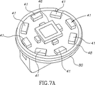
図7Aおよび図7Bは、この発明の実施例によるサポート80の代替の図である。図7Aおよび図7Bを参照すると、サポート80には、1つの面に、画像センサ46、1つまたは複数の照明源41、アンテナ48、光学分離素子170(図1Aおよび図1Bに示される)などの他の構成要素が取付けられていてもよい。図7Aに示される実施例は8つの照明源を示す。他の好適な数の照明源を使用してもよい。サポート80には、別の面に、送信機54、電源45(一実施例では電池であり得る)を保持するための電池サポート60、および他の構成要素が取付けられている。他の実施例では、電池サポートは、装置40内の1つまたは複数の構成要素に電力を供給するために電池接触を提供する構成要素であってもよい。構成要素の他のセットがサポートまたは基板のさまざまな面に含まれてもよい。
7A and 7B are alternative views of a
図1Aを再び参照すると、画像センサ46、1つまたは複数の照明源41、およびアンテナ48(これを通じて送信機54が送信することができる)は、サポートの上側または上面に位置付けられ、送信機54はサポート80の底部側または底面に位置付けられてもよい。さまざまな構成要素は、たとえば、穴または通路によってサポート80の一方の側から他方へと交差し得るサポート80上のワイヤまたは電気的な接触(図示せず)を通じて電気的に通信してもよい。
Referring again to FIG. 1A, the
装置40のさまざまな構成要素、および他の構成要素は、異なる態様でサポート80に位置付けられてもよい。たとえば、送信機54および照明源41は同じ側に位置付けられてもよい。1つまたは複数の照明源41は異なる態様で配置されてもよい。代替の実施例では、装置40のさまざまな構成要素は、ここに図示されるようにサポートまたは回路板上に取付けられるかまたは構成される必要はない。
Various components of the
この発明の一実施例では、画像化装置のセクションは光学的に互いに分離されてもよい。1つまたは複数の光学分離素子170を使用して、装置のセクションを光学的に分離し、たとえば、照明源41からの光の散乱が画像センサ46に達するのを防ぎ、画像センサセクション180を1つまたは複数の照明セクション190から分離してもよい。
In one embodiment of the invention, sections of the imaging device may be optically separated from one another. One or more
一般に、照明セクションは、少なくとも照明素子を含む領域を含み、画像化セクションは、少なくとも1つまたは複数の画像化装置を含む領域を含む。しかしながら、照明セクションは他の付加的な構成要素および領域を含んでもよく、画像化セクションは他の付加的な構成要素および領域を含んでもよい。さらに、照明セクションおよび画像化セクションの各々は、2つ以上の非連続的なセクションに分けてもよく、図示と異なる構成を有してもよい。照明部分は、LEDまたは白色LEDなどの好適な照明源を含んでもよく、他の照明源を使用してもよい。 In general, the illumination section includes an area that includes at least a lighting element, and the imaging section includes an area that includes at least one or more imaging devices. However, the lighting section may include other additional components and regions, and the imaging section may include other additional components and regions. Further, each of the illumination section and the imaging section may be divided into two or more non-consecutive sections and may have a different configuration than shown. The illumination portion may include a suitable illumination source, such as an LED or a white LED, and other illumination sources may be used.
或る実施例では、アンテナ48は、装置40内で最小限のスペースを占有するように構成されてもよい。たとえば、アンテナ48は、大量の空間を占有しないように、サポートなどの他の素子に組合わされるか、その内部、実質的にその内部に埋込まれるか、またはそこに装着されてもよい。アンテナ48は、サポート、隔離または分離素子等の構成要素によって囲まれるかまたはその中に収められてもよい。
In certain embodiments,
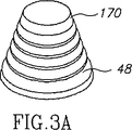
一実施例では、アンテナ48は、光学分離素子170の表面内に位置付けられるかまたはそこに取付けられる。図1Aに示される実施例では、アンテナ48は、たとえば、分離素子170の2つのセクションの間に置かれるか、または分離素子170内に成形される
かもしくは埋込まれることによって、分離素子170内でぐるぐる巻かれるか、またはその内部もしくは実質的にその内部に埋込まれてもよい(一部分が外側に延在してもよい)。図3Aは、一実施例による光学分離素子170およびアンテナ48を示す。図3Bは、一実施例による光学分離素子170およびアンテナ48を示す切欠図である。図3Cは、一実施例によるアンテナ48を示す。図3Aを参照すると、光学分離素子170は、一実施例では円錐形であってもよく、アンテナ48は光学分離素子170の外側に巻きつけられてもよい。図3bを参照すると、アンテナ48は分離素子170の内側にぐるぐる巻かれてもよい。アンテナ48は光学素子170内またはその上に位置付けられる必要はなく、分離素子170は含まれる必要はない。光学分離素子170は他の好適な形状であってもよい(たとえば、図5)。代替の実施例では、異なる形を有する他の好適な数の光学分離素子が使用されてもよい。光学分離素子は、たとえば、照明源または画像センサ、ドームまたはレンズに一体化されるかそこから延在する片、透光性または半透明の部材などの装置の構成要素の延在部であってもよく、もしくは他の好適な形であってもよい。
In one embodiment,
別の実施例では、アンテナ48はサポート80に取付けられてもよい。たとえば、アンテナ48は、サポート80の表面にわたって平坦に取付けられてもよい(図2A)。図2Aでは、アンテナ48はサポート80の周囲に配置されている。またはこれに代えて、アンテナ48は、異なる態様またはパターンでサポート80に配置されてもよい。たとえば、アンテナ48は、サポート80内に埋込まれるかまたは実質的にサポート80内に埋込まれてもよい。
In another embodiment,
送信機54は、たとえば、サポート80上のワイヤまたは接続(図示せず)によって、もしくはサポート80を通じてアンテナ48に接続されてもよい(この場合、たとえばアンテナ48および送信機54はサポート80の反対側にあり得る)。代替の実施例では、アンテナは少量の空間を占有するように構成されなくてもよい。
The
図1Aを再び参照すると、典型的には、装置は1つまたは複数の電池などの電源45を含む。たとえば、電源45は、酸化銀電池、リチウム電池、または高エネルギ密度を有する他の電気化学的セル等を含み得る。他の好適な電源を使用してもよい。外部源からの電力の導入を使用してもよい。
Referring again to FIG. 1A, the device typically includes a
一実施例では、装置40の重心(「c.g.」)の場所対幾何学的な中心は、装置40がそれ自身のサイズよりも大きな腔に入るときに装置40の光学的な軸の安定のために重要であり得る。1つまたは複数の重りまたはバラスト74が装置40の一部分、たとえば下方部分72の底部に含まれてもよい(底部および上部は相対的な言葉であり、文脈に応じて交換可能である)。重り74は装置40の他の部分に含まれてもよい。重りまたはバラストは、装置の他の機能的な構成要素の形をとってもよく、たとえば、装置の重量またはマスバランスを変更するように電池が位置付けられてもよい。比重を減少させ得るカウンタウエイトまたは他の素子が含まれてもよく、たとえば、比重または重量の分布を変更するために装置の一部分に気体が含まれてもよい。重り74は、装置40がGI管を横切る間に実質的に1つの向きを保持するように、またはその方向から動かされたときにそのような向きに戻るように配置されてもよい。重心は、典型的には視野の方向と反対であってもよい。他の実施例では、重りは、たとえば、既存の重りに釣り合うように、および、たとえば、重心を装置の幾何学的な中心に置くように、装置40の一部分に含まれてもよい。この発明の一実施例では、装置40は特定の向きを保持しないように構成されてもよい。
In one embodiment, the location of the center of gravity (“c.g.”) of the
他の構成要素および構成要素のセットを使用してもよい。たとえば、電源は、電力を装置に伝送する外部電源であってもよく、送信機54とは別のコントローラを使用してもよい。
Other components and sets of components may be used. For example, the power source may be an external power source that transmits power to the device, and a controller separate from the
一実施例では、画像センサ46は相補型金属酸化物半導体(CMOS)画像センサであってもよい。CMOS画像センサは、典型的には超低電力画像センサであり、チップスケールのパッケージング(CSP)で提供されてもよい。1つの好適なCMOSカメラは、たとえば、「チップ上カメラ(camera on a chip)」CMOS画像センサであり得る。他の種類のCMOS画像センサを使用してもよい。別の実施例では、CCD画像センサなどの他の好適な画像センサ、または他の好適な画像センサを使用してもよい。典型的には、画像センサは正方形の形状であってもよい(たとえば、256x256のCMOSアレイ)。他の寸法、たとえば、512x512の素子を使用してもよい。たとえば、長方形などの他の形状、または他の好適な形状を使用してもよい。
In one embodiment,
生体内画像装置40は、画像または他の情報を受信機システムに送信し、画像および他の情報は表示システムに表示され得る。一実施例では、上述のWO 01/65995号および/または米国特許第5,604,531号の実施例に説明されるような受信および表示システムを使用してもよい。代替の実施例では、他の構成を有する他の受信または表示システムを使用してもよい。
In-
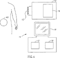
図4は、この発明の一実施例による画像化システムの素子を示す。図4を参照すると、受信機12は、患者の体外の1つまたは複数の場所にあることが好ましく、装置40から画像および他のデータを受取るためのアンテナまたはアンテナのアレイ15、画像および他のデータを記憶するための受信機記憶ユニット16、データプロセッサ14、データプロセッサ記憶ユニット19、装置40によって送信され受信機12によって記録される画像をとりわけ表示するための画像モニタ18を含むことが好ましい。典型的には、受信機12および受信機記憶ユニット16は、小型かつ携帯可能であり、画像の記録中に患者の体に着用することができる。典型的には、データプロセッサ14、データプロセッサ記憶ユニット19およびモニタ18はパーソナルコンピュータまたはワークステーションの一部であってもよく、これは、プロセッサ13、メモリ(たとえば、記憶装置19または他のメモリ)、ディスクドライブ(図示せず)、入出力装置(図示せず)などの標準的な構成要素を含み得るが、代替の構成も可能である。
FIG. 4 shows the elements of an imaging system according to one embodiment of the present invention. Referring to FIG. 4, the receiver 12 is preferably located at one or more locations outside the patient's body, and may receive an image or
代替の実施例では、データ受信および記憶構成要素は別の構成であってもよい。他の実施例は無線装置ではなく有線の装置を含み得ることを強調すべきである。そのような場合、図1Aおよび図4に示される或る素子、たとえば、送信機54、アンテナ48、アンテナアレイ15および受信機12は省略してもよい。
In alternative embodiments, the data reception and storage component may be another configuration. It should be emphasized that other embodiments may include wired devices rather than wireless devices. In such a case, certain elements shown in FIGS. 1A and 4 such as
典型的には、装置40は患者によって飲込み可能であってもよく、たとえば、患者のGI管を横切るが、しかしながら、他の体の内腔または腔を画像化するかまたは調べてもよく、装置は飲込み可能である必要はない。典型的には、装置40は別々の部分で情報(たとえば、画像情報)を送信してもよい。各部分は、たとえば、典型的には画像またはフレームに対応する。他の好適な送信方法も可能である。たとえば、装置40は、画像または他の情報を2分の1秒ごとに一度捕らえ、そのような画像を捕らえた後、たとえば、その情報を受信アンテナに送信してもよい。他の捕捉速度も可能である。典型的には、記録および送信される画像データは、デジタルカラー画像データであり得るが、代替の実施例では、他の画像フォーマット(たとえば、白黒画像データ)を使用してもよい。一実施例では、画像データの各フレームは各々が256画素の256行を含んでもよく、各画素は既知の方法による色および輝度のためのデータを含む。たとえば、各画素では、色は4つのサブピクセルのモザイクによって表現され、各サブピクセルは、赤、緑または青などの原色に対応する(1つの原色が2回表現され得る)。全体的な画素の輝度は、たとえば、1バイト(すなわち、0〜255)の輝度値によって記録され得る。他のデータフォーマットを使用してもよく、他の画像フォーマットを使用してもよい。
Typically, the
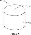
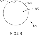
図5Aは、この発明の一実施例による光学分離素子の側面図である。図5Bは、この発明の一実施例による光学分離素子の上面図である。図5Aおよび図5Bを参照すると、光学分離素子170は、プラスチック、ポリマー、または他の好適な材料の1つの比較的平坦なリングまたは円錐であってもよい。たとえば、ABS(アクリルニトリルブタジエンスチレン)を使用してもよい。分離素子170は、他の形であってもよく、たとえば、図3の円錐形であってもよく、他の好適な材料(2つ以上の材料を含む)から作られてもよく、複数の片から構成されてもよい。アンテナ(図1A)は、分離素子170内またはその上に含まれてもよい。たとえば、アンテナは分離素子170の材料内に成形されてもよく、または分離素子170の表面(たとえば、内面171または外面172)に取付けられてもよい。
FIG. 5A is a side view of an optical separation element according to an embodiment of the present invention. FIG. 5B is a top view of the optical separation element according to one embodiment of the present invention. Referring to FIGS. 5A and 5B, the
図1Aでは、分離素子170は、たとえば断面で示される単一のリングとして示されるが、他の好適な形を有してもよい。光学分離素子170は、たとえば、不透明または透明なバリア、遮光装置、光学フィルタ、一連の別々のバリア、または他の好適な構造であってもよい。
In FIG. 1A, the
分離素子170は、たとえば、接着、音波溶接(acoustic welding)、摩擦嵌合によって装置40に取付けられてもよく、他の組立てられた構成要素、または他の方法によって保持されてもよい。分離素子170は、たとえば、サポート80などの支持表面などの他の素子の延在部の一部であってもよい。分離素子170は、たとえば、照明セクション190と画像化セクション180とを分離してもよく、これは図1Aでは、たとえば、一般に照明セクション190内にあり得る。図示の実施例では、画像化セクション180は丸く、照明セクション190はリング形または実質的にリング形であり得る。
装置の実施例は、典型的に自律的および典型的に自蔵式であり得る。たとえば、装置はカプセルまたは他のユニットであってもよく、すべての構成要素が実質的に容器または外殻内に含まれ、装置は、たとえば電力を受取るためまたは情報を送信するためにワイヤまたはケーブルを必要としない。装置は、外部の受信および表示システムと通信して、データの表示、制御または他の機能を提供してもよい。たとえば、電力は内部電池または無線受信システムによって提供されてもよい。他の実施例は他の構成および能力を有してもよい。たとえば、構成要素は複数の場所またはユニットにわたって分散されてもよい。制御情報は外部源から受取られてもよい。 Device embodiments can be typically autonomous and typically self-contained. For example, the device may be a capsule or other unit and all components are substantially contained within a container or shell, and the device may be a wire or cable, for example, for receiving power or transmitting information Do not need. The device may communicate with an external receiving and display system to provide data display, control or other functions. For example, power may be provided by an internal battery or a wireless reception system. Other embodiments may have other configurations and capabilities. For example, the components may be distributed across multiple locations or units. Control information may be received from an external source.
一実施例では、画像化装置は球形または実質的に球形であってもよい(ここで使用される場合、長円形を含む)。そのような形状によって、装置は、胃などの体の腔の典型的に湿った表面上を滑るかまたは転がることができる。さらに、球形の装置は、GI(胃腸)管の内腔壁(胃壁)に形成された隆起上を滑るかまたは転がることができ、これら隆起内または隆起上にくっつかない。そのような場合、装置内の画像センサの動きは、比較的滑らかかつ連続的であり得る。これは、たとえば表面を転がるときに同じ状況で揺れる動きおよび非連続的な画像を生成し得る他の形状(たとえば、長楕円形)の装置とは対照的であり得る。 In one embodiment, the imaging device may be spherical or substantially spherical (including an oval as used herein). Such a shape allows the device to slide or roll over the typically wet surface of a body cavity such as the stomach. Furthermore, the spherical device can slide or roll over ridges formed in the lumen wall (gastric wall) of the GI (gastrointestinal) tract, and does not stick into or on these ridges. In such cases, the movement of the image sensor within the device can be relatively smooth and continuous. This may be in contrast to other shaped (eg, elliptical) devices that may produce, for example, swaying motions and discontinuous images in the same situation when rolling over the surface.
任意のバラストまたは重りによって、画像センサ46などの一部分を通常上方に向けることができる。そのような実施例では、捕えられた画像は、装置が内腔の表面にある場合に装置があり得る壁のものではなく、その壁から外側に向けられた視野を含み得る。比較的大きい内腔(たとえば、胃または大腸)では、ある態様で重力がバラストまたは重りに作用するように患者が向けられる場合、装置があり得る壁と反対の壁が画像化され、画像装置の視野をさえぎり得る、装置に近い壁は画像化されない。そのような実施例は、比較的安定した内腔の視野を提供することができ、画像化されるのが望ましいそのような内腔
の部分に容易に向けることができる。
Any ballast or weight can cause a portion of the
図6は、この発明の一実施例による患者の胃200の中の装置40を示す。図6を参照すると、重りまたはバラスト74が装置40に含まれ得る場合、装置40は画像センサ46(図1A)が一般に上方に向けられるように向けられてもよい。したがって、胃200が、上部200′が底部200″の上方にあるように向けられると仮定すると、画像センサ46は、たとえば、aとして示される方向で画像を捕らえることができ、bで示される方向では一般に画像を捕らえない。
FIG. 6 shows a
装置が「遠い壁」から内腔の1つの壁を画像化する実施例では、その照明源は典型的には、遠い壁が適切に照明されるように十分な光を出力する。画像装置によって必要な光の量またはそれによって受取られる光の量の検出に応答して、照明ユニットによって出力される光の量を変更するさまざまな方法を使用してもよい。画像装置から出力される光を変更するための装置および方法の実施例は、ここにその全体が引用により援用され、この発明と同じ譲受人に譲渡された、2002年7月26日出願の国際出願第PCT/IL02/00622号に説明される。ここにさまざまな実施例で説明されるアンテナは、たとえば、実質的に球形または或る形状を有する装置では使用される必要はない。たとえば、そのようなアンテナは長楕円形の装置で使用されてもよい。同様に、ここにさまざまな実施例で説明されるような回路板または一連の回路板は、実質的に球形または或る形状を有する装置で使用される必要はない。たとえば、そのような構成は長楕円形の装置で使用されてもよい。さらに、球形または実質的に球形を有するこの発明の実施例による画像化装置は、ここに説明されるようなアンテナ、またはここに説明されるような回路板もしくは内部構成を含む必要はない。 In embodiments where the device images one wall of the lumen from the “far wall”, the illumination source typically outputs enough light so that the far wall is properly illuminated. Various methods of changing the amount of light output by the lighting unit in response to detecting the amount of light required by or received by the imaging device may be used. An example of an apparatus and method for changing the light output from an imaging device is hereby incorporated by reference in its entirety and assigned to the same assignee as the present invention. This is described in application PCT / IL02 / 00622. The antennas described in the various embodiments herein need not be used, for example, in devices that are substantially spherical or have a certain shape. For example, such an antenna may be used in an oval device. Similarly, a circuit board or series of circuit boards as described herein in various embodiments need not be used in a device having a substantially spherical or certain shape. For example, such a configuration may be used in an oval device. Further, an imaging device according to an embodiment of the present invention having a spherical or substantially spherical shape need not include an antenna as described herein, or a circuit board or internal configuration as described herein.
この発明の実施例によると、実質的に球形の生体内画像化装置を製造する方法が提供される。一実施例によると、この方法は、画像センサおよび送信機を1つのサポートに取付けるステップと、実質的に球形のハウジングにサポートを封止するステップとを含み得る。一部の実施例によると、画像センサおよび送信機は、サポートの2つの面、典型的には対向する面に取付けられてもよい。この発明の実施例によるサポートおよび/またはハウジングは、たとえば、上述のようなものであり得る。 According to an embodiment of the present invention, a method for manufacturing a substantially spherical in-vivo imaging device is provided. According to one embodiment, the method may include attaching the image sensor and transmitter to one support and sealing the support in a substantially spherical housing. According to some embodiments, the image sensor and transmitter may be mounted on two sides of the support, typically opposite sides. The support and / or housing according to embodiments of the invention can be, for example, as described above.
図8は、この発明の一実施例による画像化装置の製造のための方法のステップのセットを示す。図8を参照すると、ステップ100では、画像センサおよび送信機が1つのサポートに取付けられる。代替の実施例では、付加的な構成要素がサポートに取付けられてもよく、さまざまな構成要素の構成は変わり得る。たとえば、アンテナはサポートの、送信機とは異なる面または側に取付けられてもよい。さらに別の実施例では、他の構成要素の構成が実現され、たとえば、画像センサおよび送信機は同じサポートに取付けられる必要はない。
FIG. 8 shows a set of method steps for the manufacture of an imaging device according to an embodiment of the invention. Referring to FIG. 8, in
ステップ110では、サポートは実質的に球形のハウジングに囲まれるか、または封止されてもよい。他の構成要素が含まれてもよく、たとえば、バラストまたは他の重りがハウジング内に含まれてもよい。
In
他のステップまたは一連のステップを使用してもよい。 Other steps or series of steps may be used.
この発明を限られた数の実施例に関して説明してきたが、この発明の範囲および精神内で多くの変形例、修正例および他の応用例が可能であることが理解されるであろう。 Although the invention has been described with respect to a limited number of embodiments, it will be understood that many variations, modifications and other applications are possible within the scope and spirit of the invention.
Claims (14)
前記ハウジング(52,53)は、送信機(54)と画像センサ(46)が取付けられたサポート(80)と、バラスト重り(74)とを封止し、
前記バラスト重り(74)は、前記生体内画像化装置(40)の幾何学的な中心から前記生体内画像化装置(40)の重心に向かう方向が、前記生体内画像化装置(40)の視野の方向とは反対になるように、前記ハウジング(52,53)内に配置されることを特徴とする、生体内画像化装置(40)。An in-vivo imaging device (40) having a spherical housing (52, 53) comprising:
The housing (52, 53) seals the support (80) to which the transmitter (54) and the image sensor (46) are attached, and the ballast weight (74);
The ballast weight (74) has a direction from the geometric center of the in-vivo imaging device (40) toward the center of gravity of the in-vivo imaging device (40) of the in-vivo imaging device (40). An in-vivo imaging device (40), wherein the in-vivo imaging device (40) is arranged in the housing (52, 53) so as to be opposite to the direction of the visual field .
請求項1記載の生体内画像化装置(40)。The support (80) is a printed circuit board, a plastic board, or a plastic sheet.
The in-vivo imaging device (40) according to claim 1.
請求項1記載の生体内画像化装置(40)。Further comprising an antenna (48),
The in-vivo imaging device (40) according to claim 1.
請求項3記載の生体内画像化装置(40)。The antenna (48) is attached to the support (80);
The in-vivo imaging device (40) according to claim 3.
請求項3記載の生体内画像化装置(40)。The antenna (48) is mounted around the support (80);
The in-vivo imaging device (40) according to claim 3.
前記分離素子(170)は、照明源からの光が、画像化される対象からの反射に対抗して前記画像センサ(46)に直接到達するのを防止することによって、前記生体内画像化装置(40)のセクションを、互いから光学的に部分的または全体的に分離するのを支援するように構成されている、
請求項1記載の生体内画像化装置(40)。The in-vivo imaging device (40) further comprises a separation element (170),
The separation element (170) prevents the light from the illumination source from directly reaching the image sensor (46) against reflection from the object to be imaged, thereby allowing the in-vivo imaging device (40) sections configured to assist in optical partial or total separation from each other;
The in-vivo imaging device (40) according to claim 1.
エンスチレンからなる、
請求項6記載の生体内画像化装置(40)。The separation element (170) is made of plastic, polymer, or acrylonitrile butadiene styrene.
The in-vivo imaging device (40) according to claim 6.
請求項6記載の生体内画像化装置(40)。The separation element (170) is an extension part of a component of the in-vivo imaging device (40).
The in-vivo imaging device (40) according to claim 6.
請求項6記載の生体内画像化装置(40)。The separation element (170) supports the optical system (50);
The in-vivo imaging device (40) according to claim 6.
請求項1記載の生体内画像化装置(40)。The image sensor (46) is a CCD or a CMOS,
The in-vivo imaging device (40) according to claim 1.
請求項1記載の生体内画像化装置(40)。The in-vivo imaging device (40) further comprises an optical system (50) comprising a focal length between 0 mm and 40 mm.
The in-vivo imaging device (40) according to claim 1.
画像センサ(46)と送信機(54)を、単一のサポート(80)に取付けることと;
球形のハウジング(52,53)によって、前記サポート(80)を封止することと
を含み、
前記生体内画像化装置(40)の幾何学的な中心から前記生体内画像化装置(40)の重心に向かう方向が、前記生体内画像化装置(40)の視野の方向とは反対になるように、前記ハウジング(52,53)内において前記バラスト重り(74)を配置することを特徴とする、生体内画像化装置(40)の製造方法。A method for manufacturing a spherical in-vivo imaging device (40), the manufacturing method comprising:
Attaching the image sensor (46) and transmitter (54) to a single support (80);
Sealing the support (80) with a spherical housing (52, 53);
The direction from the geometric center of the in-vivo imaging device (40) to the center of gravity of the in-vivo imaging device (40) is opposite to the direction of the visual field of the in-vivo imaging device (40). Thus, the method for manufacturing an in-vivo imaging device (40) , wherein the ballast weight (74) is arranged in the housing (52, 53) .
前記製造方法は更に、
前記送信機(54)を、前記第1面に取付けることと;、
アンテナ(48)を、前記第2面に取付けることと
を含む、
請求項12記載の製造方法。The support (80) has a first surface and a second surface facing away from each other;
The manufacturing method further includes:
Attaching the transmitter (54) to the first surface;
Attaching an antenna (48) to the second surface;
The manufacturing method of Claim 12.
請求項12記載の方法。The housing (52, 53) has a transparent dome (52),
The method of claim 12.
Applications Claiming Priority (2)
| Application Number | Priority Date | Filing Date | Title |
|---|---|---|---|
| US43600402P | 2002-12-26 | 2002-12-26 | |
| PCT/IL2003/001105 WO2004059568A1 (en) | 2002-12-26 | 2003-12-25 | In vivo imaging device and method of manufacture thereof |
Publications (2)
| Publication Number | Publication Date |
|---|---|
| JP2006512131A JP2006512131A (en) | 2006-04-13 |
| JP4549865B2 true JP4549865B2 (en) | 2010-09-22 |
Family
ID=32682314
Family Applications (1)
| Application Number | Title | Priority Date | Filing Date |
|---|---|---|---|
| JP2004563551A Expired - Fee Related JP4549865B2 (en) | 2002-12-26 | 2003-12-25 | In-vivo imaging device and manufacturing method thereof |
Country Status (5)
| Country | Link |
|---|---|
| US (1) | US7637865B2 (en) |
| EP (1) | EP1576530A4 (en) |
| JP (1) | JP4549865B2 (en) |
| AU (1) | AU2003288517A1 (en) |
| WO (1) | WO2004059568A1 (en) |
Families Citing this family (28)
| Publication number | Priority date | Publication date | Assignee | Title |
|---|---|---|---|---|
| US7485093B2 (en) | 2002-04-25 | 2009-02-03 | Given Imaging Ltd. | Device and method for in-vivo sensing |
| US7833151B2 (en) * | 2002-12-26 | 2010-11-16 | Given Imaging Ltd. | In vivo imaging device with two imagers |
| US20050124875A1 (en) * | 2003-10-01 | 2005-06-09 | Olympus Corporation | Vivo observation device |
| US7909756B2 (en) * | 2005-01-26 | 2011-03-22 | Karl Storz Imaging, Inc. | Illumination system for variable direction of view instruments |
| JP4987333B2 (en) * | 2005-03-31 | 2012-07-25 | ギブン イメージング リミテッド | In-vivo imaging device and manufacturing method thereof |
| JP4827667B2 (en) * | 2006-09-07 | 2011-11-30 | オリンパスメディカルシステムズ株式会社 | Capsule endoscope |
| CN102178506A (en) * | 2006-09-12 | 2011-09-14 | 奥林巴斯医疗株式会社 | In-vivo information acquisition device, and capsule endoscope |
| US7967745B2 (en) * | 2006-09-28 | 2011-06-28 | Given Imaging, Ltd. | In vivo imaging device and method of manufacture thereof |
| KR100876647B1 (en) * | 2006-11-22 | 2009-01-08 | 주식회사 코렌 | Capsule type photographing device and method |
| AU2007322906B2 (en) * | 2006-11-24 | 2011-01-20 | Olympus Medical Systems Corp. | Encapsulated endoscope |
| JP2008142410A (en) | 2006-12-12 | 2008-06-26 | Olympus Corp | Intra-subject introduction device |
| US8702591B2 (en) * | 2007-01-12 | 2014-04-22 | Olympus Medical Systems Corp. | Capsule medical apparatus |
| US20080161639A1 (en) * | 2006-12-28 | 2008-07-03 | Olympus Medical Systems Corporation | Capsule medical apparatus and body-cavity observation method |
| US8035734B2 (en) * | 2007-04-02 | 2011-10-11 | Kenneth R Jones | Self-balancing remote sensing device and remote sensing system comprising same |
| US7733418B2 (en) * | 2007-04-02 | 2010-06-08 | Alan Edward Kaplan | Encapsulated self-balancing remote video camera system |
| US20090088618A1 (en) | 2007-10-01 | 2009-04-02 | Arneson Michael R | System and Method for Manufacturing a Swallowable Sensor Device |
| US8235903B2 (en) | 2007-10-12 | 2012-08-07 | Innoscion, Llc | Remotely controlled implantable transducer and associated displays and controls |
| US20090105532A1 (en) * | 2007-10-22 | 2009-04-23 | Zvika Gilad | In vivo imaging device and method of manufacturing thereof |
| JP5248911B2 (en) | 2008-05-09 | 2013-07-31 | オリンパスメディカルシステムズ株式会社 | Capsule medical device |
| US8636653B2 (en) | 2008-06-09 | 2014-01-28 | Capso Vision, Inc. | In vivo camera with multiple sources to illuminate tissue at different distances |
| CN102686143B (en) * | 2010-01-29 | 2015-05-20 | 奥林巴斯医疗株式会社 | Manufacturing method of capsule medical device |
| US8903497B2 (en) * | 2010-09-30 | 2014-12-02 | Medtronic, Inc. | Conformal antenna for implantable medical device and implantable medical device with such antenna |
| JP5913870B2 (en) * | 2011-08-31 | 2016-04-27 | オリンパス株式会社 | Capsule medical device |
| EP2819584B1 (en) | 2012-02-17 | 2020-04-08 | Progenity, Inc. | Ingestible medical device |
| JP2015043567A (en) * | 2013-08-20 | 2015-03-05 | サムソン エレクトロ−メカニックス カンパニーリミテッド. | Camera module and electronic device including the same |
| EP3060096A4 (en) * | 2013-10-22 | 2017-11-15 | Lu, Ganyu | System and method for capsule device with multiple phases of density |
| CN104983385B (en) * | 2015-05-21 | 2017-01-04 | 大连理工大学 | An active and passive dual hemispherical capsule robot and its attitude adjustment and turning drive control method |
| CN116726361A (en) | 2018-11-19 | 2023-09-12 | 比奥拉治疗股份有限公司 | Methods and devices for treating diseases with biologic therapeutic agents |
Family Cites Families (168)
| Publication number | Priority date | Publication date | Assignee | Title |
|---|---|---|---|---|
| US458441A (en) * | 1891-08-25 | Square for rafter and stair work | ||
| US414339A (en) * | 1889-11-05 | Time-recording device for dynamo-electric machines | ||
| US3683890A (en) | 1970-10-02 | 1972-08-15 | Charles B Beal | Carrier system for delivery of an end of an elongated member to the upper gastrointestinal tract |
| US3971362A (en) | 1972-10-27 | 1976-07-27 | The United States Of America As Represented By The Administrator Of The National Aeronautics And Space Administration | Miniature ingestible telemeter devices to measure deep-body temperature |
| US4262632A (en) | 1974-01-03 | 1981-04-21 | Hanton John P | Electronic livestock identification system |
| US4172446A (en) | 1974-12-20 | 1979-10-30 | Louis Bucalo | Apparatus for collecting body fluids |
| US4239040A (en) | 1976-10-19 | 1980-12-16 | Kabushiki Kaisha Daini Seikosha | Capsule for medical use |
| US4109644A (en) | 1977-01-12 | 1978-08-29 | The United States Of America As Represented By The United States National Aeronautics And Space Administration | Miniature implantable ultrasonic echosonometer |
| US4178735A (en) | 1977-07-13 | 1979-12-18 | The Kendall Company | Method of sheathing catheter |
| US4481952A (en) | 1978-03-22 | 1984-11-13 | Jerzy Pawelec | Device for the study of the alimentary canal |
| JPS5519124A (en) | 1978-07-27 | 1980-02-09 | Olympus Optical Co | Camera system for medical treatment |
| US5993378A (en) | 1980-10-28 | 1999-11-30 | Lemelson; Jerome H. | Electro-optical instruments and methods for treating disease |
| US4803992A (en) | 1980-10-28 | 1989-02-14 | Lemelson Jerome H | Electro-optical instruments and methods for producing same |
| JPS57156736A (en) | 1981-03-23 | 1982-09-28 | Olympus Optical Co | Therapeutic capsule apparatus |
| DE3337455A1 (en) | 1982-10-15 | 1984-04-19 | Olympus Optical Co., Ltd., Tokio/Tokyo | ENDOSCOPIC PHOTOGRAPHER |
| DE3440177A1 (en) | 1984-11-02 | 1986-05-15 | Friedrich Dipl.-Ing. 8031 Eichenau Hilliges | Television recording and replay device for endoscopy on human and animal bodies |
| US4689621A (en) | 1986-03-31 | 1987-08-25 | The United States Of America As Represented By The Administrator Of The National Aeronautics And Space Administration | Temperature responsive transmitter |
| JPS6349125A (en) | 1986-08-16 | 1988-03-01 | 奥津 一郎 | Guide pipe for endoscope |
| US4901143A (en) | 1988-02-16 | 1990-02-13 | Olympus Optical Co., Ltd. | Electronic endoscope system provided with a means of imaging frozen pictures having few picture image smears |
| US4936823A (en) | 1988-05-04 | 1990-06-26 | Triangle Research And Development Corp. | Transendoscopic implant capsule |
| US4844076A (en) | 1988-08-26 | 1989-07-04 | The Johns Hopkins University | Ingestible size continuously transmitting temperature monitoring pill |
| DE3836349A1 (en) | 1988-10-25 | 1990-05-03 | Forschungsgesellschaft Fuer Bi | CATHETER FOR MEASURING MOTILITY AND PERISTALTICS IN HOSE-SHAPED ORGANS WHICH CONTAIN THEIR CONTENT BY SIMULTANEOUS MULTIPLE IMPEDANCE MEASUREMENT |
| US5010412A (en) | 1988-12-27 | 1991-04-23 | The Boeing Company | High frequency, low power light source for video camera |
| US4940997A (en) | 1989-08-08 | 1990-07-10 | Hewlett-Packard Company | Out-of-ink sensing method |
| EP0419729A1 (en) | 1989-09-29 | 1991-04-03 | Siemens Aktiengesellschaft | Position finding of a catheter by means of non-ionising fields |
| US5081041A (en) | 1990-04-03 | 1992-01-14 | Minnesota Mining And Manufacturing Company | Ionic component sensor and method for making and using same |
| GB9018660D0 (en) | 1990-08-24 | 1990-10-10 | Imperial College | Probe system |
| JP3164609B2 (en) | 1990-10-31 | 2001-05-08 | オリンパス光学工業株式会社 | Endoscope device |
| US5267033A (en) | 1990-11-28 | 1993-11-30 | Dai Nippon Printing Co., Ltd. | Hollow body inspection system, hollow body inspection apparatus and signal transmission apparatus |
| CA2060067A1 (en) | 1991-01-28 | 1992-07-29 | Lilip Lau | Stent delivery system |
| JP2768029B2 (en) * | 1991-02-19 | 1998-06-25 | 日新電機株式会社 | Digestive system diagnostic device |
| US5279607A (en) | 1991-05-30 | 1994-01-18 | The State University Of New York | Telemetry capsule and process |
| US5395366A (en) | 1991-05-30 | 1995-03-07 | The State University Of New York | Sampling capsule and process |
| US5330427A (en) | 1991-07-02 | 1994-07-19 | Ortho Pharmaceutical Corporation | Prefilled suppository applicator |
| US5211165A (en) | 1991-09-03 | 1993-05-18 | General Electric Company | Tracking system to follow the position and orientation of a device with radiofrequency field gradients |
| US5241170A (en) | 1992-02-19 | 1993-08-31 | Itt Corporation | Fiber optic imaging device and methods |
| FR2688997A1 (en) | 1992-03-26 | 1993-10-01 | Lambert Alain | Autonomous telemetric capsule for exploring small bowel - contains sampler for carrying out mucous biopsies, radio transmitter and position detector |
| AT399229B (en) | 1992-04-23 | 1995-04-25 | Avl Verbrennungskraft Messtech | SENSOR ARRANGEMENT FOR DIRECT OR INDIRECT OPTICAL DETERMINATION OF PHYSICAL OR CHEMICAL PARAMETERS |
| JPH05316431A (en) | 1992-05-06 | 1993-11-26 | Sony Corp | Solid-state image pickup device |
| US6449006B1 (en) | 1992-06-26 | 2002-09-10 | Apollo Camera, Llc | LED illumination system for endoscopic cameras |
| JP3432825B2 (en) | 1992-08-14 | 2003-08-04 | ブリテイッシュ・テレコミュニケーションズ・パブリック・リミテッド・カンパニー | Positioning system |
| US5337732A (en) | 1992-09-16 | 1994-08-16 | Cedars-Sinai Medical Center | Robotic endoscopy |
| US5495114A (en) | 1992-09-30 | 1996-02-27 | Adair; Edwin L. | Miniaturized electronic imaging chip |
| US5368366A (en) * | 1993-03-05 | 1994-11-29 | Mizelle; Ned W. | Shallow profile legrest and furniture |
| JP3020376B2 (en) | 1993-03-26 | 2000-03-15 | サージミヤワキ株式会社 | Internal body identification device for animals |
| JPH06327624A (en) | 1993-05-21 | 1994-11-29 | Olympus Optical Co Ltd | Electronic endoscope equipment |
| US5398670A (en) | 1993-08-31 | 1995-03-21 | Ethicon, Inc. | Lumen traversing device |
| AU7924694A (en) | 1993-10-01 | 1995-05-01 | Target Therapeutics, Inc. | Sheathed multipolar catheter and multipolar guidewire for sensing cardiac electrical activity |
| US5479935A (en) | 1993-10-21 | 1996-01-02 | Synectics Medical, Inc. | Ambulatory reflux monitoring system |
| ZA948393B (en) | 1993-11-01 | 1995-06-26 | Polartechnics Ltd | Method and apparatus for tissue type recognition |
| IL108352A (en) * | 1994-01-17 | 2000-02-29 | Given Imaging Ltd | In vivo video camera system |
| US6570617B2 (en) | 1994-01-28 | 2003-05-27 | California Institute Of Technology | CMOS active pixel sensor type imaging system on a chip |
| EP0672427A1 (en) | 1994-03-17 | 1995-09-20 | Siemens-Elema AB | System for infusion of medicine into the body of a patient |
| CA2145232A1 (en) | 1994-03-24 | 1995-09-25 | Sightline Technologies Ltd. | Viewing method and apparatus particularly useful for viewing the interior of the large intestine |
| JP3434564B2 (en) * | 1994-04-11 | 2003-08-11 | オリンパス光学工業株式会社 | Endoscope |
| US5569292A (en) | 1995-02-01 | 1996-10-29 | Ethicon Endo-Surgery, Inc. | Surgical penetration instrument with transparent blades and tip cover |
| GB2308267B (en) | 1995-08-25 | 2000-06-28 | Psc Inc | Optical reader with imaging array having reduced pattern density |
| US5837196A (en) | 1996-01-26 | 1998-11-17 | The Regents Of The University Of California | High density array fabrication and readout method for a fiber optic biosensor |
| US5833603A (en) | 1996-03-13 | 1998-11-10 | Lipomatrix, Inc. | Implantable biosensing transponder |
| EA001070B1 (en) | 1996-04-01 | 2000-10-30 | Валерий Иванович КОБОЗЕВ | Electrical gastro-intestinal tract stimulator |
| JP3662072B2 (en) * | 1996-06-07 | 2005-06-22 | オリンパス株式会社 | Medical capsule device |
| US5754313A (en) | 1996-07-17 | 1998-05-19 | Welch Allyn, Inc. | Imager assembly |
| US5734418A (en) | 1996-07-17 | 1998-03-31 | Welch Allyn, Inc. | Endoscope with tab imager package |
| GB9619470D0 (en) | 1996-09-18 | 1996-10-30 | Univ London | Imaging apparatus |
| US20020057294A1 (en) | 1996-12-06 | 2002-05-16 | Satoshi Ejima | Information processing apparatus |
| US5908294A (en) | 1997-06-12 | 1999-06-01 | Schick Technologies, Inc | Dental imaging system with lamps and method |
| US6149581A (en) | 1997-06-12 | 2000-11-21 | Klingenstein; Ralph James | Device and method for access to the colon and small bowel of a patient |
| US6324418B1 (en) | 1997-09-29 | 2001-11-27 | Boston Scientific Corporation | Portable tissue spectroscopy apparatus and method |
| US5984875A (en) | 1997-08-22 | 1999-11-16 | Innotek Pet Products, Inc. | Ingestible animal temperature sensor |
| US6043839A (en) | 1997-10-06 | 2000-03-28 | Adair; Edwin L. | Reduced area imaging devices |
| US5929901A (en) | 1997-10-06 | 1999-07-27 | Adair; Edwin L. | Reduced area imaging devices incorporated within surgical instruments |
| US7030904B2 (en) | 1997-10-06 | 2006-04-18 | Micro-Medical Devices, Inc. | Reduced area imaging device incorporated within wireless endoscopic devices |
| US5986693A (en) | 1997-10-06 | 1999-11-16 | Adair; Edwin L. | Reduced area imaging devices incorporated within surgical instruments |
| US6240312B1 (en) | 1997-10-23 | 2001-05-29 | Robert R. Alfano | Remote-controllable, micro-scale device for use in in vivo medical diagnosis and/or treatment |
| US6369812B1 (en) | 1997-11-26 | 2002-04-09 | Philips Medical Systems, (Cleveland), Inc. | Inter-active viewing system for generating virtual endoscopy studies of medical diagnostic data with a continuous sequence of spherical panoramic views and viewing the studies over networks |
| IL122716A0 (en) | 1997-12-22 | 1998-08-16 | Tally Eitan Zeev Pearl And Co | System and method for in vivo delivery of autonomous capsule |
| US6174291B1 (en) | 1998-03-09 | 2001-01-16 | Spectrascience, Inc. | Optical biopsy system and methods for tissue diagnosis |
| US6084229A (en) | 1998-03-16 | 2000-07-04 | Photon Vision Systems, Llc | Complimentary metal oxide semiconductor imaging device |
| US6395562B1 (en) | 1998-04-22 | 2002-05-28 | The Regents Of The University Of California | Diagnostic microarray apparatus |
| US6086606A (en) * | 1998-05-06 | 2000-07-11 | Knodel; Bryan D. | Manually-operable surgical tool suitable for laparoscopic operations, readily adaptable for different functions by quick change of tissue-contacting operational elements |
| JP2000078596A (en) | 1998-08-31 | 2000-03-14 | Mitsubishi Electric Corp | Video camera |
| IL126727A (en) | 1998-10-22 | 2006-12-31 | Given Imaging Ltd | Method for delivering a device to a target location |
| US6228048B1 (en) | 1998-10-23 | 2001-05-08 | Cm Robbins Company Inc. | Colonic irrigation apparatus and method |
| US6145393A (en) | 1998-11-27 | 2000-11-14 | Canton; Dino | Floated gimbal optical platform |
| EP1148810B1 (en) | 1999-01-26 | 2005-11-16 | Newton Laboratories, Inc. | Autofluorescence imaging system for endoscopy |
| US7116352B2 (en) | 1999-02-25 | 2006-10-03 | Visionsense Ltd. | Capsule |
| US8636648B2 (en) | 1999-03-01 | 2014-01-28 | West View Research, Llc | Endoscopic smart probe |
| US6088606A (en) | 1999-03-22 | 2000-07-11 | Spectrx, Inc. | Method and apparatus for determining a duration of a medical condition |
| US6285897B1 (en) | 1999-04-07 | 2001-09-04 | Endonetics, Inc. | Remote physiological monitoring system |
| JP2000019390A (en) * | 1999-04-27 | 2000-01-21 | Olympus Optical Co Ltd | Objective lens |
| US6233476B1 (en) | 1999-05-18 | 2001-05-15 | Mediguide Ltd. | Medical positioning system |
| JP3462795B2 (en) | 1999-06-07 | 2003-11-05 | ペンタックス株式会社 | Swallowable endoscope device |
| JP3793368B2 (en) | 1999-06-07 | 2006-07-05 | ペンタックス株式会社 | Swallowing endoscope device |
| JP3490932B2 (en) | 1999-06-07 | 2004-01-26 | ペンタックス株式会社 | Swallowable endoscope device |
| IL143258A0 (en) | 2001-05-20 | 2002-04-21 | Given Imaging Ltd | A method for in vivo imaging of the gastrointestinal tract in unmodified conditions |
| US20020015952A1 (en) | 1999-07-30 | 2002-02-07 | Anderson Norman G. | Microarrays and their manufacture by slicing |
| GB2352636B (en) | 1999-08-03 | 2003-05-14 | Univ College London Hospitals | Improved passage-travelling device |
| IL131242A0 (en) | 1999-08-04 | 2001-01-28 | Given Imaging Ltd | A method for temperature sensing |
| JP2001091860A (en) | 1999-09-22 | 2001-04-06 | Asahi Optical Co Ltd | Capsule endoscope |
| JP2001095755A (en) | 1999-09-30 | 2001-04-10 | Asahi Optical Co Ltd | Capsule endoscope |
| JP2001095756A (en) | 1999-09-30 | 2001-04-10 | Asahi Optical Co Ltd | Capsule endoscope |
| JP2001104287A (en) | 1999-10-04 | 2001-04-17 | Asahi Optical Co Ltd | Capsule endoscope |
| JP2001104242A (en) | 1999-10-04 | 2001-04-17 | Asahi Optical Co Ltd | Capsule endoscope |
| JP2001104241A (en) | 1999-10-04 | 2001-04-17 | Asahi Optical Co Ltd | Capsule endoscope |
| JP2001104244A (en) | 1999-10-04 | 2001-04-17 | Asahi Optical Co Ltd | Capsule endoscope |
| JP2001104243A (en) | 1999-10-04 | 2001-04-17 | Asahi Optical Co Ltd | Capsule endoscope |
| JP2001112710A (en) | 1999-10-20 | 2001-04-24 | Asahi Optical Co Ltd | Capsule endoscope |
| JP2001112740A (en) | 1999-10-20 | 2001-04-24 | Asahi Optical Co Ltd | Capsule endoscope |
| JP2001112709A (en) | 1999-10-20 | 2001-04-24 | Asahi Optical Co Ltd | Capsule endoscope |
| JP4472069B2 (en) | 1999-11-10 | 2010-06-02 | オリンパス株式会社 | Medical capsule endoscope |
| GB2357856B (en) | 1999-12-29 | 2001-12-19 | Keymed | Annular light source in borescopes and endoscopes |
| IL134017A (en) | 2000-01-13 | 2008-04-13 | Capsule View Inc | Camera for viewing inside intestines |
| EP1350103B1 (en) | 2000-01-19 | 2010-01-06 | Given Imaging Ltd. | A system for detecting substances |
| US7039453B2 (en) | 2000-02-08 | 2006-05-02 | Tarun Mullick | Miniature ingestible capsule |
| JP4338280B2 (en) | 2000-02-15 | 2009-10-07 | Hoya株式会社 | Capsule endoscope |
| JP2001224553A (en) | 2000-02-17 | 2001-08-21 | Asahi Optical Co Ltd | Imaging device for capsule endoscope |
| JP4360730B2 (en) * | 2000-02-21 | 2009-11-11 | Hoya株式会社 | Capsule endoscope |
| JP2001245844A (en) | 2000-03-03 | 2001-09-11 | Asahi Optical Co Ltd | Capsule endoscope |
| IL177381A0 (en) | 2000-03-08 | 2006-12-10 | Given Imaging Ltd | A device for in vivo imaging |
| IL142026A (en) | 2000-03-14 | 2008-04-13 | Yissum Res Dev Co | Device and method for in vitro detection of blood |
| JP3488170B2 (en) | 2000-03-21 | 2004-01-19 | オリンパス株式会社 | Endoscope |
| US6692430B2 (en) | 2000-04-10 | 2004-02-17 | C2Cure Inc. | Intra vascular imaging apparatus |
| US6475145B1 (en) | 2000-05-17 | 2002-11-05 | Baymar, Inc. | Method and apparatus for detection of acid reflux |
| IL143418A (en) | 2000-05-31 | 2004-09-27 | Given Imaging Ltd | Measurement of electrical characteristics of tissue |
| JP2002130262A (en) * | 2000-10-27 | 2002-05-09 | Ntn Corp | Bearing with non-contact signal transmitting mechanism |
| US6632175B1 (en) | 2000-11-08 | 2003-10-14 | Hewlett-Packard Development Company, L.P. | Swallowable data recorder capsule medical device |
| US6929636B1 (en) | 2000-11-08 | 2005-08-16 | Hewlett-Packard Development Company, L.P. | Internal drug dispenser capsule medical device |
| JP2004524076A (en) | 2001-01-11 | 2004-08-12 | ギブン・イメージング・リミテツド | Apparatus and system for in vivo procedures |
| EP1358460B1 (en) | 2001-01-16 | 2008-03-19 | Given Imaging Ltd. | System for determining in vivo body lumen conditions |
| IL156961A0 (en) | 2001-01-16 | 2004-02-08 | Given Imaging Ltd | System and method for wide field imaging of body lumens |
| ES2365696T3 (en) | 2001-03-14 | 2011-10-10 | Given Imaging Ltd. | METHOD AND SYSTEM TO DETECT COLORIMETRIC ABNORMALITIES. |
| US7616238B2 (en) | 2001-03-29 | 2009-11-10 | Given Imaging Ltd. | Method for timing control of an image sensor |
| US7119814B2 (en) | 2001-05-18 | 2006-10-10 | Given Imaging Ltd. | System and method for annotation on a moving image |
| IL143260A (en) | 2001-05-20 | 2006-09-05 | Given Imaging Ltd | Array system and method for locating an in vivo signal source |
| IL143259A (en) | 2001-05-20 | 2006-08-01 | Given Imaging Ltd | Method for moving an object through the colon |
| JP2002345743A (en) * | 2001-05-28 | 2002-12-03 | Fuji Photo Film Co Ltd | Capsule endoscope |
| DE60228266D1 (en) | 2001-06-18 | 2008-09-25 | Given Imaging Ltd | SWITCHABLE IN VIVO CAPSULE WITH A RIGID AND FLEXIBLE SECTION CIRCUIT BOARD |
| US6939292B2 (en) | 2001-06-20 | 2005-09-06 | Olympus Corporation | Capsule type endoscope |
| IL159451A0 (en) | 2001-06-20 | 2004-06-01 | Given Imaging Ltd | Motility analysis within a gastrointestinal tract |
| EP1421775A4 (en) | 2001-06-28 | 2009-12-23 | Given Imaging Ltd | In vivo imaging device with a small cross sectional area and methods for construction thereof |
| US6702847B2 (en) | 2001-06-29 | 2004-03-09 | Scimed Life Systems, Inc. | Endoluminal device with indicator member for remote detection of endoleaks and/or changes in device morphology |
| US6934573B1 (en) | 2001-07-23 | 2005-08-23 | Given Imaging Ltd. | System and method for changing transmission from an in vivo sensing device |
| US20030117491A1 (en) | 2001-07-26 | 2003-06-26 | Dov Avni | Apparatus and method for controlling illumination in an in-vivo imaging device |
| US20030043263A1 (en) | 2001-07-26 | 2003-03-06 | Arkady Glukhovsky | Diagnostic device using data compression |
| US6951536B2 (en) | 2001-07-30 | 2005-10-04 | Olympus Corporation | Capsule-type medical device and medical system |
| JP4744026B2 (en) | 2001-07-30 | 2011-08-10 | オリンパス株式会社 | Capsule endoscope and capsule endoscope system |
| US20030028078A1 (en) | 2001-08-02 | 2003-02-06 | Arkady Glukhovsky | In vivo imaging device, system and method |
| IL160179A0 (en) | 2001-08-02 | 2004-07-25 | Given Imaging Ltd | Apparatus and methods for in vivo imaging |
| CN100354889C (en) | 2001-09-05 | 2007-12-12 | 吉温成象有限公司 | System and method for three dimensional display of body lumens |
| EP1432345B1 (en) | 2001-09-24 | 2011-11-09 | Given Imaging Ltd. | System for controlling a device in vivo |
| IL147221A (en) | 2001-12-20 | 2010-11-30 | Given Imaging Ltd | Device, system and method for image based size analysis |
| US6939290B2 (en) | 2002-02-11 | 2005-09-06 | Given Imaging Ltd | Self propelled device having a magnetohydrodynamic propulsion system |
| IL154391A (en) | 2002-02-11 | 2009-05-04 | Given Imaging Ltd | Self propelled device |
| WO2003069913A1 (en) | 2002-02-12 | 2003-08-21 | Given Imaging Ltd. | System and method for displaying an image stream |
| US7474327B2 (en) | 2002-02-12 | 2009-01-06 | Given Imaging Ltd. | System and method for displaying an image stream |
| US20030195415A1 (en) | 2002-02-14 | 2003-10-16 | Iddan Gavriel J. | Device, system and method for accoustic in-vivo measuring |
| JP4363843B2 (en) | 2002-03-08 | 2009-11-11 | オリンパス株式会社 | Capsule endoscope |
| JP3895618B2 (en) | 2002-03-08 | 2007-03-22 | オリンパス株式会社 | Capsule endoscope |
| JP4009473B2 (en) | 2002-03-08 | 2007-11-14 | オリンパス株式会社 | Capsule endoscope |
| US20030216622A1 (en) | 2002-04-25 | 2003-11-20 | Gavriel Meron | Device and method for orienting a device in vivo |
| US7473218B2 (en) | 2002-08-06 | 2009-01-06 | Olympus Corporation | Assembling method of capsule medical apparatus |
| JP4109927B2 (en) | 2002-08-20 | 2008-07-02 | セイコークロック株式会社 | Radio correction watch and method |
| AU2003269438A1 (en) | 2002-09-30 | 2004-04-19 | Given Imaging Ltd. | In-vivo sensing system |
| US7662093B2 (en) | 2002-09-30 | 2010-02-16 | Given Imaging, Ltd. | Reduced size imaging device |
| AU2003274646A1 (en) | 2002-10-21 | 2004-05-04 | Given Imaging Ltd. | Intubation and imaging device and system |
| US7118529B2 (en) | 2002-11-29 | 2006-10-10 | Given Imaging, Ltd. | Method and apparatus for transmitting non-image information via an image sensor in an in vivo imaging system |
| IL155175A (en) | 2003-03-31 | 2012-01-31 | Given Imaging Ltd | Diagnostic device using data compression |
| JP4144533B2 (en) | 2004-02-24 | 2008-09-03 | ソニー株式会社 | Playback apparatus and method |
-
2003
- 2003-12-25 WO PCT/IL2003/001105 patent/WO2004059568A1/en not_active Ceased
- 2003-12-25 EP EP03780592A patent/EP1576530A4/en not_active Withdrawn
- 2003-12-25 US US10/540,888 patent/US7637865B2/en not_active Expired - Fee Related
- 2003-12-25 JP JP2004563551A patent/JP4549865B2/en not_active Expired - Fee Related
- 2003-12-25 AU AU2003288517A patent/AU2003288517A1/en not_active Abandoned
Also Published As
| Publication number | Publication date |
|---|---|
| JP2006512131A (en) | 2006-04-13 |
| US20060056828A1 (en) | 2006-03-16 |
| EP1576530A1 (en) | 2005-09-21 |
| US7637865B2 (en) | 2009-12-29 |
| EP1576530A4 (en) | 2009-03-25 |
| WO2004059568A1 (en) | 2004-07-15 |
| AU2003288517A1 (en) | 2004-07-22 |
Similar Documents
| Publication | Publication Date | Title |
|---|---|---|
| JP4549865B2 (en) | In-vivo imaging device and manufacturing method thereof | |
| US7833151B2 (en) | In vivo imaging device with two imagers | |
| JP5203962B2 (en) | Capsule endoscope | |
| US7553276B2 (en) | Method and device for imaging body lumens | |
| EP1251777B1 (en) | Encapsulated medical imaging device | |
| JP4598498B2 (en) | Intra-subject introduction device | |
| EP3270761B1 (en) | Capsule device having variable specific gravity | |
| US20070106112A1 (en) | Device, system and method for in-vivo imaging of a body lumen | |
| US20050137468A1 (en) | Device, system, and method for in-vivo sensing of a substance | |
| WO2011092673A1 (en) | Spherical capsule video endoscopy | |
| WO2006045011A2 (en) | Endocapsule | |
| JP5248911B2 (en) | Capsule medical device | |
| JP2006043276A (en) | System for obtaining intra-subject image and intra-subject introduction device | |
| US20090281389A1 (en) | Device, system, and method for adaptive imaging | |
| JP2005334452A (en) | Intrasubject information acquisition apparatus | |
| JP2007044214A (en) | In vivo information acquisition device | |
| WO2004058043A2 (en) | Method for in vivo sensing | |
| IL174552A (en) | In vivo imaging device and method of manufacture thereof | |
| IL161202A (en) | Method and device for imaging body lumens |
Legal Events
| Date | Code | Title | Description |
|---|---|---|---|
| A621 | Written request for application examination |
Free format text: JAPANESE INTERMEDIATE CODE: A621 Effective date: 20061222 |
|
| RD03 | Notification of appointment of power of attorney |
Free format text: JAPANESE INTERMEDIATE CODE: A7423 Effective date: 20081210 |
|
| A521 | Request for written amendment filed |
Free format text: JAPANESE INTERMEDIATE CODE: A821 Effective date: 20081225 |
|
| RD04 | Notification of resignation of power of attorney |
Free format text: JAPANESE INTERMEDIATE CODE: A7424 Effective date: 20081225 |
|
| A977 | Report on retrieval |
Free format text: JAPANESE INTERMEDIATE CODE: A971007 Effective date: 20091106 |
|
| A131 | Notification of reasons for refusal |
Free format text: JAPANESE INTERMEDIATE CODE: A131 Effective date: 20091124 |
|
| A521 | Request for written amendment filed |
Free format text: JAPANESE INTERMEDIATE CODE: A523 Effective date: 20100224 |
|
| TRDD | Decision of grant or rejection written | ||
| A01 | Written decision to grant a patent or to grant a registration (utility model) |
Free format text: JAPANESE INTERMEDIATE CODE: A01 Effective date: 20100615 |
|
| A01 | Written decision to grant a patent or to grant a registration (utility model) |
Free format text: JAPANESE INTERMEDIATE CODE: A01 |
|
| A61 | First payment of annual fees (during grant procedure) |
Free format text: JAPANESE INTERMEDIATE CODE: A61 Effective date: 20100707 |
|
| R150 | Certificate of patent or registration of utility model |
Free format text: JAPANESE INTERMEDIATE CODE: R150 |
|
| FPAY | Renewal fee payment (event date is renewal date of database) |
Free format text: PAYMENT UNTIL: 20130716 Year of fee payment: 3 |
|
| S802 | Written request for registration of partial abandonment of right |
Free format text: JAPANESE INTERMEDIATE CODE: R311802 |
|
| FPAY | Renewal fee payment (event date is renewal date of database) |
Free format text: PAYMENT UNTIL: 20130716 Year of fee payment: 3 |
|
| FPAY | Renewal fee payment (event date is renewal date of database) |
Free format text: PAYMENT UNTIL: 20130716 Year of fee payment: 3 |
|
| R350 | Written notification of registration of transfer |
Free format text: JAPANESE INTERMEDIATE CODE: R350 |
|
| R250 | Receipt of annual fees |
Free format text: JAPANESE INTERMEDIATE CODE: R250 |
|
| R250 | Receipt of annual fees |
Free format text: JAPANESE INTERMEDIATE CODE: R250 |
|
| R250 | Receipt of annual fees |
Free format text: JAPANESE INTERMEDIATE CODE: R250 |
|
| R250 | Receipt of annual fees |
Free format text: JAPANESE INTERMEDIATE CODE: R250 |
|
| R250 | Receipt of annual fees |
Free format text: JAPANESE INTERMEDIATE CODE: R250 |
|
| LAPS | Cancellation because of no payment of annual fees |