JP4547803B2 - Agricultural tractor work machine coupling device - Google Patents
Agricultural tractor work machine coupling device Download PDFInfo
- Publication number
- JP4547803B2 JP4547803B2 JP2000397626A JP2000397626A JP4547803B2 JP 4547803 B2 JP4547803 B2 JP 4547803B2 JP 2000397626 A JP2000397626 A JP 2000397626A JP 2000397626 A JP2000397626 A JP 2000397626A JP 4547803 B2 JP4547803 B2 JP 4547803B2
- Authority
- JP
- Japan
- Prior art keywords
- rotary tiller
- shaft
- tractor
- transmission shaft
- work machine
- Prior art date
- Legal status (The legal status is an assumption and is not a legal conclusion. Google has not performed a legal analysis and makes no representation as to the accuracy of the status listed.)
- Expired - Fee Related
Links
Images


Description
【0001】
【発明の属する技術分野】
この発明は、農用トラクタの作業機連結装置の改良に関する。
【0002】
【従来技術】
従来の農用トラクタの作業機連結装置として、上部リンク及び下部リンクを構成要素とする3点連結式の昇降装置で作業機ヒッチを昇降自在に構成し、この作業機ヒッチにロータリ耕耘装置等の作業機を吊り下げるようにして、作業機を迅速に連結する装置は、公知である。
【0003】
【発明が解決しようとする課題】
トラクタの後部の機体ヒッチに設けられている左・右2Pセットピンに作業機を上下回動自在に2点連結式の作業機連結方法では、作業機を同様に迅速に連結するものは存在しない。また、PTO軸に連動連結する屈折伝動軸のジョイント部とロータリ耕耘装置の動力取入軸との芯合わせが容易でない。
【0004】
この発明は、3点連結式の作業機ヒッチを2点連結式でトラクタの機体後部に装着し、作業機ヒッチに迅速に作業機を連結し、また、PTO軸に連動連結する屈折伝動軸のジョイント部とロータリ耕耘装置の動力取入軸との芯合わせを容易の行わせようとするものである。
【0005】
【課題を解決するための手段】
このような技術的課題を解決するための請求項1の発明は、トラクタ側の左・右2Pセットプレート26,26の左・右2Pセットピン12,12に、ロータリ耕耘装置15側の連結ステー27,27の左・右2P連結凹部28,28を連結し、ロータリ耕耘装置15を2点連結式で上下回動自在に連結する農用トラクタの作業機連結装置において、トラクタの機体後部にPTO軸を後方へ突出するように設け、このPTO軸に屈折伝動軸22の前端部を伝動連結し、軸受30を備え上記屈折伝動軸22の後端のジョイント部22aを支持するジョイントサポート29を、前記左・右2Pセットピン12,12の軸芯回りに回動自在に支持し、該ジョイントサポート29が上・下ストッパ31,31に当接する所定範囲で回動し屈折伝動軸22の後側のジョイント部22aが上下回動するよう構成し、前記屈折伝動軸22を、前記ロータリ耕耘装置15の伝動ボックス18から前方に突出する動力取入軸24に伝動連結すべく設けた農用トラクタの作業機連結装置とする。
また、請求項2の発明は、請求項1において、左・右2Pセットプレート26,26に、ジョイントサポート29に固着されている左・右2Pセットピン12,12を支持し、該左・右2Pセットピン12,12に長手の回動規制具32を固着し、この回動規制具32が前後方向水平状態となると、ロータリ耕耘装置15の連結状態における屈折伝動軸22のジョイント部22aとロータリ耕耘装置15側の動力取入軸24との軸芯が一致状態となるよう構成した。
【0006】
【発明の作用及び効果】
請求項1に記載の発明は、トラクタ機体を後退させてロータリ耕耘装置15に接近させながら、左・右2Pセットプレート26,26の左・右2Pセットピン12,12を、ロータリ耕耘装置15側の左・右2P連結凹部28,28に嵌合装着し、抜け止めピンでロックし、ロータリ耕耘装置15を上下回動自在に連結するが、この接近しながらの嵌合装着過程で、ジョイントサポート29を上下回動し、屈折伝動軸22のジョイント部22aとロータリ耕耘装置15側の動力取入軸24との芯合わせをし伝動連結状態とする。
このように、トラクタ機体とロータリ耕耘装置15との近接移動時に、ジョイントサポート29を上下回動することにより、屈折伝動軸22のジョイント部22aと動力取入軸24との芯合わせを容易に行なうことができ、ロータリ耕耘装置15の装着を容易化することができる。
また、請求項2に記載の発明は、請求項1の作用効果に加え、ロータリ耕耘装置15側の左・右2P連結凹部28,28が左・右2Pセットピン12,12の回動規制具32に嵌合しながら接近すると、回動規制具32が前後方向水平になるように回動し、ジョイントサポート29の回動が規制されて、屈折伝動軸22のジョイント部22aとロータリ耕耘装置15側の動力取入軸24との芯合わせが自動的になされ、連結を一層容易なものにすることができる。
【0007】
【発明の実施の形態】
以下、本発明の一実施例の形態について説明する。まず、図1〜図3について説明する。トラクタ1の機体2の後部にはPTO軸3を後方に突出するように設け、機体後側上部に取り付けたリフトボックス4に、左・右リフトアーム5,5を上下回動自在に設け、昇降油圧シリンダ(図示省略)の伸縮により、左・右リフトアーム5,5を上下回動する構成としている。
【0008】
6は3点で作業機を連結することのできる3P型の作業機ヒッチで、次ぎのように構成されている。作業機ヒッチ6の枠組み構成は、背面視で逆U字形の上部枠体6aと、上部枠体6aの下端部相互間を左右方向に連結する下部枠体6bにより構成されている。この上部枠体6aの上端部中央には凹部で構成されている作業機上連結部7を設け、下部枠体6bの左右両側部には、凹部8aと回動係止体8bとからなる作業機下連結部8,8を設け、これらの作業機上連結部7及び作業機下連結部8,8により作業機の3点連結部を構成している。
【0009】
作業機ヒッチ6の下部両側部からピン連結した左・右下ステー9,9を前側に延出し、作業機ヒッチ6の上部枠体6aの上部と左・右下ステー9,9の前後方向中間部とを固定ステー13,13により連結し、作業機ヒッチ6を上方に突出する姿勢に、左・右下ステー9,9を前方に突出する姿勢に保持している。左・右下ステー9,9の前端部に設けている凹形の2P連結部10,10を、トラクタ1側の機体ヒッチ11の左・右2Pセットピン12,12に嵌合して係止ピンにより抜け止めをし、機体ヒッチ11に対して左・右下ステー9,9の前側部を上下回動自在に連結する構成である。
【0010】
そして、左・右リフトアーム5,5にリフトリンク14,14の前端部をピン連結し、リフトリンク14,14の後端部を作業機ヒッチ6の上部枠体6aの中途部にピン連結し、左・右リフトアーム5,5の上下回動により、作業機ヒッチ6を昇降させる構成としている。
【0011】
ロータリ耕耘装置15のトップマスト16の上端部には、作業機ヒッチ6側の作業機上連結部7に嵌合する上連結ピン17を設け、伝動ボックス18の両側には作業機ヒッチ6側の作業機下連結部8,8に嵌合する左・右下連結ピン19,19を設けている。
【0012】
作業機ヒッチ6の下部枠体6bの左右両側部に取り付けた支持板20,20にジョイントホルダ(図示省略)を介して屈折伝動軸22を支持すると共に、屈折伝動軸22の前側を左・右下ステー9,9に連結している連結棒23で支持して前側に延出し、屈折伝動軸22の前端部を機体側のPTO軸3に連結し、後端部を作業機ヒッチ6に連結するロータリ耕耘装置15の動力取入軸(図示省略)に伝動連結する構成である。
【0013】
しかして、作業機ヒッチ6の回動係止体8bをヒッチレバー25により上方へ回動して凹部8aを開口状態とし、次いで、左・右リフトアーム5,5を上下回動操作しながら、作業機ヒッチ6側の作業機上連結部7にロータリ耕耘装置15側の上連結ピン17を嵌合支持すると共に、作業機下連結部8,8の凹部8a,8aにロータリ耕耘装置15側の左・右下連結ピン19,19を嵌合し支持する。すると、作業機下連結部8,8の凹部8a,8aへの左・右下連結ピン19,19の嵌合装着に関連して、回動係止体8b,8bは下方に回動し閉鎖状態となりロックされる。
【0014】
従来のトラクタの作業機連結装置として、上部リンク及び下部リンクを構成要素とする3点連結式の作業機昇降装置で作業機ヒッチ6を昇降自在に構成し、ロータリ耕耘装置15等の作業機を迅速に連結する連結装置はあった。しかし、機体ヒッチ11の左・右2Pセットピン12,12の2点で上下回動自在に連結する2点連結式の作業機連結方式では、作業機を同様に迅速に連結する作業機ヒッチは存在しなかった。
【0015】
この実施例では、3点連結式の作業機ヒッチ6を2点連結式の作業機ヒッチに転用し、作業機ヒッチ6の下部両側部に左・右下ステー9,9を取り付けて固定状態で前側に延出し、左・右下ステー9,9の2P連結部10,10を、トラクタ1側の左・右2Pセットピン12,12にピン連結し、左・右リフトアーム5,5にリフトリンク14,14の前端部をピン連結し、リフトリンク14,14の後端部を作業機ヒッチ6の上部側にピン連結し、左・右リフトアーム5,5の上下回動で作業機ヒッチ6を昇降させる構成としたので、2点連結式で上下回動する作業機ヒッチ6に3点連結型のロータリ耕耘装置15を迅速に装着することができる。
【0016】
次に、図4に示す作業機連結装置の実施例について説明する。トラクタ1側の左・右2Pセットプレート26,26の左・右2Pセットピン12,12に、ロータリ耕耘装置15側の連結ステー27,27の左・右2P連結凹部28,28を連結して、ロータリ耕耘装置15を2点連結式で上下回動自在に連結する構成である。
【0017】
トラクタ1の機体後部にPTO軸(図示省略)を後方へ突出するように設けて、このPTO軸に屈折伝動軸22の前端部を伝動連結する。屈折伝動軸22の後側のジョイント部22aをジョイントサポート29の軸受30で支持している。このジョイントサポート29を例えば左・右2Pセットピン12,12の軸芯回りに回動自在に支持し、ジョイントサポート29側の上・下ストッパ31,31が左・右2Pセットプレート26,26に当接するまでの所定範囲で回動し、屈折伝動軸22の後側のジョイント部22aが上下回動するように構成している。ロータリ耕耘装置15の伝動ボックス18には前方に突出するように動力取入軸24を軸架している。
【0018】
しかして、図4(2)の状態から、トラクタ1を後退させてロータリ耕耘装置15に接近させながら、左・右2Pセットプレート26,26の左・右2Pセットピン12,12を、ロータリ耕耘装置15側の左・右2P連結凹部28,28に嵌合装着し、抜け止めピンでロックし、ロータリ耕耘装置15を上下回動自在に連結する。
【0019】
そして、この接近しながらの嵌合装着過程で、ジョイントサポート29を上下回動し、屈折伝動軸22のジョイント部22aとロータリ耕耘装置15側の動力取入軸24との芯合わせをし伝動連結状態とする。このように、トラクタ1とロータリ耕耘装置15との近接移動時に、ジョイントサポート29を上下回動することにより、屈折伝動軸22のジョイント部22aと動力取入軸24との芯合わせを容易に行なうことができ、ロータリ耕耘装置15の装着を容易化することができる。
【0020】
また、図5に示すように、左・右2Pセットプレート26,26にはジョイントサポート29に固着されている左・右2Pセットピン12,12によりジョイントサポート29を軸支し、左・右2Pセットピン12,12に長手の回動規制具32を固着している。そして、この回動規制具32が前後方向水平状態となると、ロータリ耕耘装置15の連結状態における屈折伝動軸22のジョイント部22aとロータリ耕耘装置15側の動力取入軸24との軸芯が一致状態となるように構成している。
【0021】
このように構成すると、ロータリ耕耘装置15側の左・右2P連結凹部28,28が左・右2Pセットピン12,12の回動規制具32に嵌合しながら接近すると、回動規制具32が前後方向水平になるように回動し、ジョイントサポート29の回動が規制されて、屈折伝動軸22のジョイント部22aとロータリ耕耘装置15側の動力取入軸24との芯合わせが自動的になされ、連結を一層容易なものにすることができる。
【0022】
次に、図1及び図6に基づきロータリ耕耘装置15のカバー構成の他の実施例について説明する。ロータリ耕耘装置15の耕耘伝動ケース33の下端部には、耕耘軸、耕耘爪からなる耕耘装置34が設けられていて、耕耘装置34の上部を耕耘カバー35で被覆し、耕耘装置34の後部をリヤーカバー36で被覆し、耕耘カバー35の後端部とリヤーカバー36の前端部との間を、揺動ゴムカバー37で連結し、耕耘土壌がカバー内に多くなると揺動ゴムカバー37が膨らみ耕土を細かく砕土しながら耕耘する構成としている。
【0023】
この耕耘カバー35の後部左右両側部に支持片38,38を取り付け、リヤーカバー36の前端部左右両側に揺動防止プレート39,39を取り付け、揺動防止プレート39,39の前端部を支持片38,38にピン40により連結し、揺動ゴムカバー37の過度の膨らみを防止している。なお、支持片38,38の孔38aの大きさを調節することにより、揺動ゴムカバー37の揺動具合を調節することができる。
【0024】
耕耘カバー35の後端部とリヤーカバー36の前端部との間を、揺動ゴムカバー37で連結しただけの構成であると、揺動ゴムカバー37が過度に揺動して膨らみ、サイドカバーの上端よりも上方まで膨らみ、耕土が側方に飛散するという不具合があった。
【0025】
しかし、耕耘カバー35とリヤーカバー36との間を揺動防止プレート39,39で連結することにより、揺動ゴムカバー37の過度の揺動を防止し、耕土の側方からの飛散を防止することができる。次に、図1及び図7に基づきロータリ耕耘装置15のスライドヒッチ41の他の実施例について説明する。
【0026】
スライドヒッチ41の前端部を伝動ボックス18に上下回動自在に軸支し、トップマスト16に取り付けているスクリュー式の昇降調節装置42により、スライドヒッチ41を上下調節自在に支持している。このスライドヒッチ41は、左右一対の前パイプ41a、41aと、後L字型パイプ41b,直線状の後パイプ41cとにより構成し、前パイプ41a、41aに後L字型パイプ41b及び後パイプ41cの前端部を挿通支持し、支持孔43,43と複数の調節孔44,44,…とにピン45,45を差し替えることにより、後方への突出長さを調節できる構成とし、後L字型パイプ41bの後端部にヒッチ46を取り付けている。
【0027】
通常の作業時には、後L字型パイプ41bと後パイプ41cを、図7(4)に示すように平面状態とし、ヒッチ46に作業機を連結し耕耘作業との複合作業をする。この後L字型パイプ41bと後パイプ41cとの連結用のピン45を取り外し、図7(2)に示すように、前パイプ41aに対して後L字型パイプ41bを90度下方に回動した状態に、前パイプ41a,41aに付け代える。すると、図7(2),(3)に示すように、後L字型パイプ41bの下端部を接地させることにより、ロータリ耕耘装置15を起立状態で支持し、スタンドとしての機能を果たすことができる。
【図面の簡単な説明】
【図1】 全体の側面図である。
【図2】 要部の側面図である。
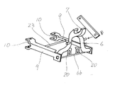
【図3】 要部の斜視図である。
【図4】 要部の側面図、側面図である。
【図5】 要部の側面図、側面図である。
【図6】 要部の斜視図である。
【図7】 要部の斜視図、側面図である。
【符号の説明】
1 トラクタ
2 機体
3 PTO軸
4 リフトボックス
5 左・右リフトアーム
6 作業機ヒッチ
6a 上部枠体
6b 下部枠体
7 作業機上連結部
8 作業機下連結部
8a 凹部
8b 回動係止体
9 左・右ステー
10 2P連結部
11 機体ヒッチ
12 左・右2Pセットピン
13 固定ステー
14 リフトリンク
15 ロータリ耕耘装置
16 トップマスト
17 上連結ピン
18 伝動ボックス
19 左・右下連結ピン
22 屈折伝動軸
22a ジョイント部
24 動力取入軸
26 2Pセットプレート
27 連結ステー
28 2P連結凹部
29 ジョイントサポート
30 軸受
31 上・下ストッパ
32 回動規制具 [0001]
BACKGROUND OF THE INVENTION
The present invention relates to an improvement of a work machine coupling device for agricultural tractors.
[0002]
[Prior art]
As a conventional agricultural machine tractor work machine connection device, a work machine hitch is configured to be movable up and down by a three-point connection type lifting device having upper and lower links as components, and a work such as a rotary tillage device can be performed on this work machine hitch. Devices for quickly connecting work machines in a manner that suspends the machine are known.
[0003]
[Problems to be solved by the invention]
In the two-point connection type work machine connection method in which the work machine can be pivoted up and down to the left and right 2P set pins provided in the machine hitch at the rear of the tractor, there is no one that quickly connects the work machines in the same manner. . Further, it is not easy to align the center of the joint portion of the refractive transmission shaft linked to the PTO shaft and the power intake shaft of the rotary tiller.
[0004]
In this invention, a three-point connection type work machine hitch is attached to the rear part of the tractor in a two-point connection type, the work machine is quickly connected to the work machine hitch, and the refraction transmission shaft connected to the PTO shaft is interlocked. the centering of the power intake Nyujiku joint portion and the rotary tiller is intended to facilitate the performed not so.
[0005]
[Means for Solving the Problems]
In order to solve such a technical problem, the invention of claim 1 is such that the left and right 2P set
Further, the invention of claim 2 supports the left and right 2P set
[0006]
[Action and effect of the invention]
In the first aspect of the invention, the left and right 2P set
As described above, when the tractor body and the
In addition to the function and effect of claim 1, the invention according to claim 2 is such that the left and right
[0007]
DETAILED DESCRIPTION OF THE INVENTION
Hereinafter, an embodiment of the present invention will be described. First, FIGS. 1 to 3 will be described. At the rear of the fuselage 2 of the tractor 1, the
[0008]
6 is a 3P type work machine hitch that can connect the work machines at three points, and is configured as follows. The framework configuration of the
[0009]
The left and right lower stays 9, 9, which are pin-connected from the lower both sides of the work implement
[0010]
Then, the front ends of the lift links 14, 14 are connected to the left and
[0011]
At the upper end of the
[0012]
The
[0013]
Then, the rotation locking body 8b of the
[0014]
As a conventional working machine connecting device for a tractor, the working
[0015]
In this embodiment, the three-point connection type
[0016]
Next, an embodiment of the work machine coupling device shown in FIG. 4 will be described. The left and right 2P set recesses 28 and 28 of the connecting stays 27 and 27 on the
[0017]
A PTO shaft (not shown) is provided at the rear of the body of the tractor 1 so as to protrude rearward, and the front end portion of the
[0018]
4 (2), the left and right 2P set pins 12 and 12 of the left and right 2P set
[0019]
Then, in this fitting and fitting process while approaching, the
[0020]
Further, as shown in FIG. 5, the left and right 2P set
[0021]
If comprised in this way, if the left / right 2P connection recessed
[0022]
Next, another embodiment of the cover configuration of the
[0023]
[0024]
If the rear end portion of the
[0025]
However, by connecting the tilling
[0026]
The front end of the
[0027]
At the time of normal work, the rear L-shaped pipe 41b and the rear pipe 41c are brought into a flat state as shown in FIG. 7 (4), and a work machine is connected to the
[Brief description of the drawings]
FIG. 1 is an overall side view.
FIG. 2 is a side view of a main part.
FIG. 3 is a perspective view of a main part.
FIG. 4 is a side view and a side view of a main part.
FIG. 5 is a side view and a side view of a main part.
FIG. 6 is a perspective view of a main part.
FIG. 7 is a perspective view and a side view of a main part.
[Explanation of symbols]
DESCRIPTION OF SYMBOLS 1 Tractor 2
26 2P set plate
27 Connecting stay
28 2P connecting recess
29 Joint support
30 Bearing
31 Upper / lower stopper
32 Rotation restrictor
Claims (2)
Priority Applications (1)
| Application Number | Priority Date | Filing Date | Title |
|---|---|---|---|
| JP2000397626A JP4547803B2 (en) | 2000-12-27 | 2000-12-27 | Agricultural tractor work machine coupling device |
Applications Claiming Priority (1)
| Application Number | Priority Date | Filing Date | Title |
|---|---|---|---|
| JP2000397626A JP4547803B2 (en) | 2000-12-27 | 2000-12-27 | Agricultural tractor work machine coupling device |
Publications (3)
| Publication Number | Publication Date |
|---|---|
| JP2002191204A JP2002191204A (en) | 2002-07-09 |
| JP2002191204A5 JP2002191204A5 (en) | 2008-01-17 |
| JP4547803B2 true JP4547803B2 (en) | 2010-09-22 |
Family
ID=18862731
Family Applications (1)
| Application Number | Title | Priority Date | Filing Date |
|---|---|---|---|
| JP2000397626A Expired - Fee Related JP4547803B2 (en) | 2000-12-27 | 2000-12-27 | Agricultural tractor work machine coupling device |
Country Status (1)
| Country | Link |
|---|---|
| JP (1) | JP4547803B2 (en) |
Families Citing this family (8)
| Publication number | Priority date | Publication date | Assignee | Title |
|---|---|---|---|---|
| JP4701527B2 (en) * | 2001-04-17 | 2011-06-15 | 井関農機株式会社 | Tractor work equipment coupling device |
| JP4563064B2 (en) * | 2004-03-30 | 2010-10-13 | 三菱農機株式会社 | Tractor work equipment coupling device |
| JP4585248B2 (en) * | 2004-07-23 | 2010-11-24 | 三菱農機株式会社 | Tractor work equipment coupling device |
| JP4732782B2 (en) * | 2005-04-13 | 2011-07-27 | 三菱農機株式会社 | Work machine assembly |
| JP4606289B2 (en) * | 2005-09-22 | 2011-01-05 | 株式会社クボタ | Work machine connection structure |
| JP4563367B2 (en) * | 2006-12-07 | 2010-10-13 | 三菱農機株式会社 | Tractor work equipment coupling device |
| JP4563366B2 (en) * | 2006-12-07 | 2010-10-13 | 三菱農機株式会社 | Tractor work equipment coupling device |
| JP5463088B2 (en) * | 2009-06-23 | 2014-04-09 | 小橋工業株式会社 | Farm machine connection device |
Citations (5)
| Publication number | Priority date | Publication date | Assignee | Title |
|---|---|---|---|---|
| JPS5023207U (en) * | 1973-06-26 | 1975-03-15 | ||
| JPS5350931U (en) * | 1976-10-04 | 1978-04-28 | ||
| JPS55123205U (en) * | 1979-02-23 | 1980-09-01 | ||
| JPH06292405A (en) * | 1993-04-09 | 1994-10-21 | Iseki & Co Ltd | Apparatus for controlling posture of working machine |
| JPH11127616A (en) * | 1997-10-29 | 1999-05-18 | Mitsubishi Agricult Mach Co Ltd | Coupling device of working machine |
Family Cites Families (3)
| Publication number | Priority date | Publication date | Assignee | Title |
|---|---|---|---|---|
| JPS6327524Y2 (en) * | 1981-04-27 | 1988-07-26 | ||
| JPS63124310U (en) * | 1987-02-04 | 1988-08-12 | ||
| JPH0737444Y2 (en) * | 1988-07-15 | 1995-08-30 | セイレイ工業株式会社 | Working machine coupling device in tractor |
-
2000
- 2000-12-27 JP JP2000397626A patent/JP4547803B2/en not_active Expired - Fee Related
Patent Citations (5)
| Publication number | Priority date | Publication date | Assignee | Title |
|---|---|---|---|---|
| JPS5023207U (en) * | 1973-06-26 | 1975-03-15 | ||
| JPS5350931U (en) * | 1976-10-04 | 1978-04-28 | ||
| JPS55123205U (en) * | 1979-02-23 | 1980-09-01 | ||
| JPH06292405A (en) * | 1993-04-09 | 1994-10-21 | Iseki & Co Ltd | Apparatus for controlling posture of working machine |
| JPH11127616A (en) * | 1997-10-29 | 1999-05-18 | Mitsubishi Agricult Mach Co Ltd | Coupling device of working machine |
Also Published As
| Publication number | Publication date |
|---|---|
| JP2002191204A (en) | 2002-07-09 |
Similar Documents
| Publication | Publication Date | Title |
|---|---|---|
| US4090725A (en) | Devices for automatically coupling implements to self-propelled vehicles | |
| US4176727A (en) | Devices for automatically coupling implements to self-propelled articles | |
| US6588513B1 (en) | Articulating hitch assembly | |
| US3791456A (en) | Tractor hitch system including a vertically swingable drawbar powered by a draft link actuator | |
| JP4547803B2 (en) | Agricultural tractor work machine coupling device | |
| PL131200B1 (en) | System for suspension implements on tractor | |
| US4102404A (en) | Articulated cultivator | |
| US4308919A (en) | Hinge-type offset wheel harrow | |
| US2713298A (en) | Integral tool carrier | |
| JPS5849051Y2 (en) | Automatic resistance control device for agricultural tractors | |
| US2751835A (en) | Tool carrier | |
| JP2002125407A (en) | Implement connecting apparatus for agricultural tractor | |
| US2796818A (en) | Stabilizer for tractor mounted implements | |
| JP3284554B2 (en) | Seedling plant with fertilizer application | |
| JP2007097596A (en) | Apparatus for connecting implement of tractor | |
| JPH0729773Y2 (en) | Holding stand for work equipment for tractors | |
| JP4155110B2 (en) | Rotary work machine | |
| US1288805A (en) | Agricultural implement. | |
| JPH0249806U (en) | ||
| JPH083212Y2 (en) | Stand for work equipment for tractors | |
| JP4563367B2 (en) | Tractor work equipment coupling device | |
| US3214190A (en) | Implement hitch | |
| JPH0139122Y2 (en) | ||
| GB2240245A (en) | A semi-trailer rotating plough | |
| JP4769529B2 (en) | Installation method of work equipment |
Legal Events
| Date | Code | Title | Description |
|---|---|---|---|
| A521 | Written amendment |
Free format text: JAPANESE INTERMEDIATE CODE: A523 Effective date: 20071122 |
|
| A621 | Written request for application examination |
Free format text: JAPANESE INTERMEDIATE CODE: A621 Effective date: 20071212 |
|
| A977 | Report on retrieval |
Free format text: JAPANESE INTERMEDIATE CODE: A971007 Effective date: 20091106 |
|
| A131 | Notification of reasons for refusal |
Free format text: JAPANESE INTERMEDIATE CODE: A131 Effective date: 20091208 |
|
| A521 | Written amendment |
Free format text: JAPANESE INTERMEDIATE CODE: A523 Effective date: 20100208 |
|
| TRDD | Decision of grant or rejection written | ||
| A01 | Written decision to grant a patent or to grant a registration (utility model) |
Free format text: JAPANESE INTERMEDIATE CODE: A01 Effective date: 20100615 |
|
| A01 | Written decision to grant a patent or to grant a registration (utility model) |
Free format text: JAPANESE INTERMEDIATE CODE: A01 |
|
| A61 | First payment of annual fees (during grant procedure) |
Free format text: JAPANESE INTERMEDIATE CODE: A61 Effective date: 20100628 |
|
| R150 | Certificate of patent or registration of utility model |
Ref document number: 4547803 Country of ref document: JP Free format text: JAPANESE INTERMEDIATE CODE: R150 Free format text: JAPANESE INTERMEDIATE CODE: R150 |
|
| FPAY | Renewal fee payment (event date is renewal date of database) |
Free format text: PAYMENT UNTIL: 20130716 Year of fee payment: 3 |
|
| LAPS | Cancellation because of no payment of annual fees |