JP4546473B2 - Penetrating energy - Google Patents
Penetrating energy Download PDFInfo
- Publication number
- JP4546473B2 JP4546473B2 JP2006523048A JP2006523048A JP4546473B2 JP 4546473 B2 JP4546473 B2 JP 4546473B2 JP 2006523048 A JP2006523048 A JP 2006523048A JP 2006523048 A JP2006523048 A JP 2006523048A JP 4546473 B2 JP4546473 B2 JP 4546473B2
- Authority
- JP
- Japan
- Prior art keywords
- solution
- solvent
- liquid
- membrane
- prime mover
- Prior art date
- Legal status (The legal status is an assumption and is not a legal conclusion. Google has not performed a legal analysis and makes no representation as to the accuracy of the status listed.)
- Expired - Fee Related
Links
Images


Classifications
-
- F—MECHANICAL ENGINEERING; LIGHTING; HEATING; WEAPONS; BLASTING
- F03—MACHINES OR ENGINES FOR LIQUIDS; WIND, SPRING, OR WEIGHT MOTORS; PRODUCING MECHANICAL POWER OR A REACTIVE PROPULSIVE THRUST, NOT OTHERWISE PROVIDED FOR
- F03G—SPRING, WEIGHT, INERTIA OR LIKE MOTORS; MECHANICAL-POWER PRODUCING DEVICES OR MECHANISMS, NOT OTHERWISE PROVIDED FOR OR USING ENERGY SOURCES NOT OTHERWISE PROVIDED FOR
- F03G7/00—Mechanical-power-producing mechanisms, not otherwise provided for or using energy sources not otherwise provided for
- F03G7/005—Electro-chemical actuators; Actuators having a material for absorbing or desorbing gas, e.g. a metal hydride; Actuators using the difference in osmotic pressure between fluids; Actuators with elements stretchable when contacted with liquid rich in ions, with UV light, with a salt solution
-
- Y—GENERAL TAGGING OF NEW TECHNOLOGICAL DEVELOPMENTS; GENERAL TAGGING OF CROSS-SECTIONAL TECHNOLOGIES SPANNING OVER SEVERAL SECTIONS OF THE IPC; TECHNICAL SUBJECTS COVERED BY FORMER USPC CROSS-REFERENCE ART COLLECTIONS [XRACs] AND DIGESTS
- Y02—TECHNOLOGIES OR APPLICATIONS FOR MITIGATION OR ADAPTATION AGAINST CLIMATE CHANGE
- Y02E—REDUCTION OF GREENHOUSE GAS [GHG] EMISSIONS, RELATED TO ENERGY GENERATION, TRANSMISSION OR DISTRIBUTION
- Y02E10/00—Energy generation through renewable energy sources
- Y02E10/40—Solar thermal energy, e.g. solar towers
- Y02E10/46—Conversion of thermal power into mechanical power, e.g. Rankine, Stirling or solar thermal engines
Landscapes
- Chemical & Material Sciences (AREA)
- Engineering & Computer Science (AREA)
- Combustion & Propulsion (AREA)
- Analytical Chemistry (AREA)
- Mechanical Engineering (AREA)
- General Engineering & Computer Science (AREA)
- Separation Using Semi-Permeable Membranes (AREA)
- External Artificial Organs (AREA)
- Engine Equipment That Uses Special Cycles (AREA)
Abstract
Description
本発明は、原動機の駆動方法に関する。本発明は、例えば、流体動力(または水力)を発生させる、原動機の駆動装置にも関する。 The present invention relates to a driving method for a prime mover. The present invention also relates to a driving apparatus for a prime mover that generates, for example, fluid power (or hydraulic power).
半透膜によって、濃縮水溶液(高い浸透ポテンシャルおよび高エントロピー)から希薄水溶液(低い浸透ポテンシャル、低いエントロピー)を分離するとき、希薄水溶液の水は、半透膜を横切って流れて、濃縮水溶液を希釈する。この現象は、浸透として知られている。 When separating a dilute aqueous solution (low osmotic potential, low entropy) from a concentrated aqueous solution (high osmotic potential and high entropy) by a semipermeable membrane, the water of the dilute aqueous solution flows across the semipermeable membrane to dilute the concentrated aqueous solution To do. This phenomenon is known as penetration.
米国特許第3978344号には、浸透エネルギーを他の形態のエネルギーに変える方法が記載されている。特に、この参照文献では、半透膜を用いて多くの海水から多くの淡水(または真水)を分離する方法が記載されている。淡水と海水との間の浸透ポテンシャルの差は、水が膜を通り抜けて海水に入ることを可能にし、結果として、膜の海水側での静水圧の増加をもたらす。この海水を加圧ストリームとして排出することができ、発電装置に連結しているタービンの回転に用いることができる。 U.S. Pat. No. 3,978,344 describes a method for converting osmotic energy into other forms of energy. In particular, this reference describes a method of separating a lot of fresh water (or fresh water) from a lot of sea water using a semipermeable membrane. The difference in osmotic potential between fresh water and seawater allows water to pass through the membrane and into the seawater, resulting in an increase in hydrostatic pressure on the seawater side of the membrane. This seawater can be discharged as a pressurized stream and can be used to rotate the turbine connected to the power generator.
半透膜を介した淡水の移動は、結果として海水の希釈をもたらし、結局は、所定量の海水からのエネルギーの生産を制限する。従って、希釈された海水に、定期的または連続的に新たな海水を補充する必要がある。 The movement of fresh water through the semipermeable membrane results in dilution of the seawater, ultimately limiting the production of energy from a given amount of seawater. Therefore, it is necessary to replenish the diluted seawater with fresh seawater regularly or continuously.
本発明は、原動機の駆動方法を提供し、該方法は、
a)液体と液体よりも高い浸透ポテンシャルを有する溶液との間に選択膜を配置し、膜を横切る液体の流入により溶液を加圧状態にすること
b)溶液において生じた圧力を用いて原動機を駆動すること
c)溶液を回収すること
d)溶液から溶媒の少なくともいくらかを分離して残留生成物を形成すること、ならびに
e)工程d)の分離溶媒および/または残留生成物を工程a)にリサイクルすること
を含んで成る。
The present invention provides a method for driving a prime mover, which comprises:
a) A selective membrane is placed between the liquid and a solution having a higher osmotic potential than the liquid, and the solution is pressurized by the inflow of the liquid across the membrane. b) The prime mover is driven using the pressure generated in the solution. C) recovering the solution d) separating at least some of the solvent from the solution to form a residual product, and e) separating the separated solvent and / or residual product of step d) into step a). Comprising recycling.
一態様において、工程d)の残留生成物を工程a)の溶液にリサイクルする。別法または追加として、分離溶媒を、工程a)における膜の液体側にリサイクルしてよい。 In one embodiment, the residual product of step d) is recycled to the solution of step a). Alternatively or additionally, the separation solvent may be recycled to the liquid side of the membrane in step a).
選択膜を横切って液体が流入することにより、溶液に圧力(例えば、静水圧)を発生させる。工程a)からの加圧溶液を直接用いて原動機を駆動してよい。別法では、工程a)からの溶液を回収してよく、また、回収溶液の溶媒のいくらかを除去してよい。生じた濃縮溶液は、工程a)にリサイクルする前に、原動機の駆動に用いてよい。別法または追加として、溶液から分離した溶媒を用いて原動機を駆動してよい。すべての場合において、工程a)の溶液において生じた圧力の少なくともいくらかを用いて、原動機を駆動する。オプションとして、溶液において生じた圧力を用いて、次の処理での溶液をポンピングしてよい。 As the liquid flows across the selective membrane, pressure (eg, hydrostatic pressure) is generated in the solution. The prime mover may be driven directly using the pressurized solution from step a). Alternatively, the solution from step a) may be recovered and some of the solvent of the recovered solution may be removed. The resulting concentrated solution may be used to drive the prime mover before being recycled to step a). Alternatively or additionally, the prime mover may be driven with a solvent separated from the solution. In all cases, the prime mover is driven using at least some of the pressure generated in the solution of step a). Optionally, the pressure generated in the solution may be used to pump the solution in the next treatment.
工程a)では、いずれの適当な選択膜を用いてもよい。膜は、1〜60Å、好ましくは2〜50Å、より好ましくは5〜40Å、例えば10〜30Åの平均ポアサイズ(または孔径:pore size)を有し得る。一態様において、膜は、12〜25Åの平均ポアサイズを有する。 Any suitable selection membrane may be used in step a). The membrane may have an average pore size (or pore size) of 1 to 60 mm, preferably 2 to 50 mm, more preferably 5 to 40 mm, such as 10 to 30 mm. In one aspect, the membrane has an average pore size of 12-25 cm.
膜の平均ポアサイズは、溶液中の溶質のサイズより好ましくは小さい。好都合にも、このことは、拡散によって膜を横切る溶質の流れを防止または減少し、液体が、浸透(エントロピー)勾配に沿って膜を横切って流れることを可能にする。膜を横切る液体の流量は、膜のポアサイズに左右される。一般に、ポアサイズが大きい程、流量はより多い。 The average pore size of the membrane is preferably smaller than the size of the solute in the solution. Advantageously, this prevents or reduces the flow of solute across the membrane by diffusion, allowing liquid to flow across the membrane along an osmotic (entropy) gradient. The flow rate of liquid across the membrane depends on the pore size of the membrane. In general, the larger the pore size, the higher the flow rate.
適当な選択膜の例として、内在性膜(integral membrane)および複合膜がある。適当な膜の具体例として、セルロースアセテート(CA)から形成された膜およびポリアミド(PA)から形成された膜を含む。好ましくは、膜は、イオン選択性膜である。常套の半透膜を用いてもよい。 Examples of suitable selective membranes are integral membranes and composite membranes. Specific examples of suitable membranes include membranes formed from cellulose acetate (CA) and membranes formed from polyamide (PA). Preferably, the membrane is an ion selective membrane. A conventional semipermeable membrane may be used.
膜は、平面であり得、またはチューブもしくは中空ファイバの形であり得る。所望により、膜は、例えばメッシュ支持体等の支持構造体によって支持されていてよい。膜は、波形または曲がりくねった形であってよい。 The membrane can be planar or in the form of a tube or hollow fiber. If desired, the membrane may be supported by a support structure such as a mesh support. The membrane may be corrugated or serpentine.
原動機は、溶液中のエネルギーを機械力(または機械原動力)に変える、いずれの適当な装置でもあってもよい。適当な原動機として、例えばタービン等の回転式原動機がある。このようにして、原動機を用いて動力を発生させることができる。 The prime mover can be any suitable device that converts energy in the solution into mechanical power (or mechanical dynamics). An example of a suitable prime mover is a rotary prime mover such as a turbine. In this way, power can be generated using the prime mover.
別法では、原動機は、圧力変換システムであってよく、またはその一部を形成していてもよい。このようにして、原動機を用いて、加圧溶液から他の流体にエネルギーを移動することもできる。適当な圧力変換システムの例が、米国特許第4887942号、第5338158号、第5988993号、および第6540487号に記載されている。圧力変換システムは、本体部分(その反対端に端エレメントを含む)を有するハウジングを含んで成り得る。ローターを、端プレートに接触させて実質的にシールしながら、本体部分に配置してよい。ローターには、その1端から反対端まで縦に広がり、各端に開口部を有する、少なくとも1つのチャンネルが備わっていてよい。使用に際し、チャンネルは、高圧液体(例えば、工程a)からの加圧溶液)と低圧液体との間の交互の水圧の伝達を提供し、液体間で圧力を移動させる。 Alternatively, the prime mover may be a pressure conversion system or may form part thereof. In this way, energy can also be transferred from the pressurized solution to other fluids using the prime mover. Examples of suitable pressure conversion systems are described in U.S. Pat. Nos. 4,888,942, 5,338,158, 5,998,993, and 6,540,487. The pressure conversion system may comprise a housing having a body portion (including an end element at its opposite end). The rotor may be disposed on the body portion while substantially contacting and sealing the end plate. The rotor may be provided with at least one channel extending longitudinally from one end to the opposite end and having an opening at each end. In use, the channel provides alternating water pressure transmission between the high pressure liquid (eg, the pressurized solution from step a) and the low pressure liquid to move the pressure between the liquids.
本発明の方法では、選択膜は、液体と溶液との間に位置する。溶液は、液体よりも高い浸透ポテンシャルを有する。従って、溶液の全溶解固形物(TDS)濃度は、典型的には、液体のそれよりも高い。 In the method of the present invention, the selective membrane is located between the liquid and the solution. The solution has a higher osmotic potential than the liquid. Thus, the total dissolved solids (TDS) concentration of the solution is typically higher than that of the liquid.
液体と溶液との間の浸透ポテンシャルの差は、溶媒に、低い浸透ポテンシャルの側(即ち、低い溶質濃度もしくは低いエントロピーまたは高い溶媒濃度)から高い浸透ポテンシャルの側(即ち、高い溶質濃度もしくは高いエントロピーまたは低い溶媒濃度)へと選択膜を通過させる。この液体の流入は、溶液の圧力の増加をもたらす。例えば、溶液の圧力は、液体の流入に起因して、105〜107Paから1.1x10⁵〜5.0x10⁷Paの圧力まで増大し得る。好ましい態様では、溶液の圧力は、液体の流入に起因して、105〜107Paから1.5x10⁵〜2.5x10⁷Paの圧力まで増大し得る。 The difference in osmotic potential between the liquid and the solution is that the solvent has a low osmotic potential side (ie low solute concentration or low entropy or high solvent concentration) to a high osmotic potential side (ie high solute concentration or high entropy). (Or low solvent concentration) through a selective membrane. This inflow of liquid results in an increase in the pressure of the solution. For example, pressure of the solution, due to the inflow of the liquid may be increased from 10 5 to 10 7 Pa to a pressure of 1.1x10 5 ~5.0x10 7 Pa. In a preferred embodiment, the pressure of the solution, due to the inflow of the liquid may be increased from 10 5 to 10 7 Pa to a pressure of 1.5x10 5 ~2.5x10 7 Pa.
本発明の方法の工程a)をハウジングで実施することができる。ハウジングは、好ましくは、選択膜の1つの側に液体を導入する入口、および該膜の反対側から加圧溶液を除去する出口が備わっている。好ましい態様では、液体の溶液への流入は十分であり、1.1x10⁵〜5.0x10⁷Pa、好ましくは1.5x10⁵〜2.5x10⁷Paの圧力でハウジングから溶液を排出する。ハウジングの出口は、適当な圧力での溶液の排出を保証する大きさにすることができる。追加または別法として、ノズル(圧力調整器)を出口に連結して、これにより溶液の圧力を調整してよい。 Step a) of the method according to the invention can be carried out on the housing. The housing is preferably equipped with an inlet for introducing liquid on one side of the selective membrane and an outlet for removing pressurized solution from the opposite side of the membrane. In a preferred embodiment, the flow of the solution of the liquid is sufficient, 1.1x10 5 ~5.0x10 7 Pa, preferably to discharge the solution from the housing at a pressure of 1.5x10 5 ~2.5x10 7 Pa. The housing outlet can be sized to ensure drainage of the solution at a suitable pressure. Additionally or alternatively, a nozzle (pressure regulator) may be connected to the outlet, thereby adjusting the pressure of the solution.
加圧溶液を、例えば、加圧ストリームとしてハウジングから除去してよい。溶液において生じる圧力を用いて原動機を駆動することができる。溶液を原動機に直接導入して、原動機を駆動し、例えば、動力を発生させることができる。別法では、溶液において生じる圧力を、圧力変換システムを介して他の液体に移してよい。工程a)からの加圧溶液を工程b)に直接用いて原動機を駆動することができる。別法では、工程b)の前に、本方法の工程c)および工程d)を実施することができる。 The pressurized solution may be removed from the housing, for example, as a pressurized stream. The pressure generated in the solution can be used to drive the prime mover. The solution can be introduced directly into the prime mover to drive the prime mover and generate power, for example. Alternatively, the pressure generated in the solution may be transferred to other liquids via a pressure conversion system. The prime mover can be driven using the pressurized solution from step a) directly in step b). Alternatively, steps c) and d) of the method can be carried out before step b).
溶液において生じる圧力は、溶液を、ハウジングから、例えば10〜2500m、好ましくは50〜1500mの高所まで排出(または噴出)するのに十分であり得る。従って、高所から溶液を原動機に導入することができる。このようにして、溶液のポテンシャルエネルギーの少なくとも一部分を機械エネルギーに変換する。続いて、原動機の機械エネルギーを、例えば、電気および/または熱等の他の形態のエネルギーに変換することができる。ある態様では、原動機に溶液を導入する前に、溶液を高い位置で保存することが望ましい。 The pressure generated in the solution may be sufficient to discharge (or squirt) the solution from the housing, for example to a height of 10-2500 m, preferably 50-1500 m. Therefore, the solution can be introduced into the prime mover from a high place. In this way, at least a portion of the potential energy of the solution is converted to mechanical energy. Subsequently, the mechanical energy of the prime mover can be converted into other forms of energy, such as electricity and / or heat, for example. In certain embodiments, it may be desirable to store the solution at an elevated location prior to introducing the solution to the prime mover.
工程c)において、溶液を回収する。次いで、回収溶液から溶媒を除去する(工程d))。この溶媒除去工程を、いずれの適当な溶媒除去/分離方法によって実施してもよい。熱および/または膜分離工程を用いてもよい。1もしくはそれより多くの熱分離工程および/または1もしくはそれより多くの膜分離工程の組み合わせを用いてもよい。 In step c), the solution is recovered. Next, the solvent is removed from the recovered solution (step d)). This solvent removal step may be performed by any suitable solvent removal / separation method. Thermal and / or membrane separation processes may be used. A combination of one or more thermal separation steps and / or one or more membrane separation steps may be used.
適当な熱分離技術の例として、蒸発、蒸留および結晶化がある。例えば、周囲条件下、空気中で溶媒を蒸発させることにより、蒸発を自然に実施することができる。別法では、蒸発を冷却塔で実施してもよい。適当な蒸留法として、多段フラッシュ蒸留法(MSF:multi-stage flash distillation)、多重効用蒸留法(MED:multi-effect distillation)、機械的蒸気圧縮法(MVC:mechanical vapour compression)、高速噴霧脱塩法(rapid spray desalination)がある。 Examples of suitable thermal separation techniques are evaporation, distillation and crystallization. For example, evaporation can be carried out naturally by evaporating the solvent in air under ambient conditions. Alternatively, evaporation may be performed in a cooling tower. Suitable distillation methods include multi-stage flash distillation (MSF), multi-effect distillation (MED), mechanical vapor compression (MVC), high-speed spray desalting. There is a rapid spray desalination.
多段フラッシュ蒸留法では、溶液を直列(または一連)のチューブに導入し、高い温度まで加熱する。次いで、加熱溶液を蒸留チャンバーに導入し、その蒸気圧よりも低い圧力に付す。圧力の突然の減少により、沸騰またはフラッシュ(蒸発:flash)を引き起こす。入ってくる溶液ストリームをチューブにおいて濃縮することにより、塩を含む残渣からフラッシュ蒸気を分離する。典型的には直列の蒸発チャンバーを用いる。このようにして、蒸発またはフラッシュ工程が多段階で起こる。 In the multistage flash distillation method, the solution is introduced into a series (or series) of tubes and heated to an elevated temperature. The heated solution is then introduced into the distillation chamber and subjected to a pressure lower than its vapor pressure. A sudden decrease in pressure causes boiling or flashing (evaporation). The flash vapor is separated from the salt-containing residue by concentrating the incoming solution stream in a tube. Typically, a series evaporation chamber is used. In this way, the evaporation or flash process takes place in multiple stages.
多重効用蒸留は、直列の効用缶(effects)で行われ、各種効用缶において、周囲圧力を下げる原理を利用する。このことは、第1効用の後に供給されるべき追加の熱を必要とすることなく、一連の段階において溶液の沸騰を可能にする。 Multiple effect distillation takes place in series effects and uses the principle of reducing the ambient pressure in various effect cans. This allows the solution to boil in a series of steps without requiring additional heat to be supplied after the first effect.
多重効用蒸留法では、溶液を予熱して、蒸発器チューブの表面に液体の薄膜としてスプレー(または噴霧)する。チューブは、チューブを通る水蒸気によって加熱する。チューブの加熱表面に接触させながら、スプレー液体を蒸発させる。この蒸気を用いて次の効用缶の蒸発器チューブを加熱し、熱の移動によってチューブにおける蒸気を凝縮させる。このようにして溶液を蒸発および凝縮することによって、溶液から溶媒を回収することができる。 In the multi-effect distillation method, the solution is preheated and sprayed (or sprayed) as a liquid film on the surface of the evaporator tube. The tube is heated by water vapor passing through the tube. The spray liquid is evaporated while in contact with the heated surface of the tube. This vapor is used to heat the evaporator tube of the next utility can and condense the vapor in the tube by the transfer of heat. By evaporating and condensing the solution in this way, the solvent can be recovered from the solution.
少なくとも1つの効用缶の蒸気を圧縮することにより、多重効用蒸留工程の効率を上げることができる。多重効用蒸留と圧縮との組み合わせは、MED−熱圧縮として知られている。 By compressing the vapor of at least one effect can, the efficiency of the multi-effect distillation process can be increased. The combination of multiple effect distillation and compression is known as MED-thermal compression.
機械的蒸気圧縮法(MVD)を用いて、溶液から溶媒を除去することもできる。機械的蒸気圧縮法では、典型的には容器から蒸気を抽出して、次いで容器内に設置されているチューブで圧縮することによって凝縮する。圧縮および凝縮工程は熱を発生させ、チューブ壁を加熱する。溶液は、チューブ表面にスプレーされるときに、更なる蒸気を発生して蒸発する。抽出、圧縮および凝縮工程を繰り返すことにより、溶液から更なる溶媒を回収することができる。 Mechanical vapor compression (MVD) can also be used to remove the solvent from the solution. In mechanical vapor compression methods, vapor is typically extracted from a container and then condensed by compression with a tube installed in the container. The compression and condensation process generates heat and heats the tube walls. As the solution is sprayed onto the tube surface, it generates additional vapor and evaporates. By repeating the extraction, compression and condensation steps, additional solvent can be recovered from the solution.
高速噴霧脱塩法(RSD)を用いて、溶液から溶媒を除去することもできる。典型的な高速噴霧脱塩法では、エアーが加熱要素を通って蒸発チャンバーに吹き込まれる。加熱エアーが蒸発チャンバーに沿って移動するとき、例えば海水の霧状溶液を、蒸発チャンバーに注入する。動いている蒸気および海水滴は、海水滴を捕捉して純粋な気相を凝縮器に通すメカニカルフィルターを通る。海水滴は、フィルターから定期的に洗い流すことができる。 The solvent can also be removed from the solution using fast spray desalting (RSD). In a typical high speed spray desalting process, air is blown through a heating element into an evaporation chamber. When heated air moves along the evaporation chamber, for example, a seawater mist solution is injected into the evaporation chamber. The moving steam and seawater droplets pass through a mechanical filter that traps the seawater droplets and passes the pure gas phase through the condenser. Seawater droplets can be periodically washed away from the filter.
上述のように、結晶化法を用いて、溶液から溶媒を分離することもできる。結晶化作用により、溶液中の溶媒または溶質を結晶化することができる。 As described above, the solvent can also be separated from the solution using a crystallization method. The solvent or solute in the solution can be crystallized by the crystallization action.
例えば、溶媒の凝固点まで溶液を冷却することにより、結晶化を行うことができる。これにより、溶液中の溶媒の少なくともいくらかを結晶化させる。次いで、この結晶化された溶媒を除去することができる。結晶化には冷涼な環境が好ましく、低い周囲温度を用いて溶液温度を下げて、結晶化をもたらすことができる。 For example, crystallization can be performed by cooling the solution to the freezing point of the solvent. This causes at least some of the solvent in the solution to crystallize. The crystallized solvent can then be removed. A cool environment is preferred for crystallization, and low ambient temperatures can be used to lower the solution temperature to effect crystallization.
別法では、熱分離塔を用いて結晶化を行うことができる。例えば、溶解している溶質の少なくともいくらかが溶液から沈殿するように、溶液を熱分離カラムで冷却する。これらの沈殿物は、溶質濃度が減少した溶液をカラムの上部に残しながら、カラムの底部に集めて回収することができる。好適には、温度変化に敏感な溶解度を有する塩を用いて溶液を生成してもよい。好ましくは、そのような塩は、低温で溶液から容易に沈殿する。そのような塩の例として、リン酸水素2ナトリウム(Na2HPO4・12H2O)等のリン酸水素がある。 Alternatively, crystallization can be performed using a thermal separation tower. For example, the solution is cooled with a thermal separation column so that at least some of the dissolved solute precipitates out of the solution. These precipitates can be collected and collected at the bottom of the column, leaving a solution with reduced solute concentration at the top of the column. Preferably, the solution may be formed using a salt having a solubility sensitive to temperature changes. Preferably, such salts readily precipitate from solution at low temperatures. An example of such a salt is hydrogen phosphate such as disodium hydrogen phosphate (Na 2 HPO 4 · 12H 2 O).
一態様において、工程a)からの溶液を高所(例えば山頂)に移すことができ、高所の周囲温度は、i)溶液において溶質種を結晶化するのに十分低いか、またはii)溶媒を結晶化する溶液の凝固点よりも下であるか、いずれかである。このことは、溶液を2つの部に分離させる。1の部は、低い溶質濃度を有するが、他の部は、より高い溶質濃度を有する。溶液のポテンシャルエネルギーを用いて原動機を駆動することができるように、これらの各溶液を地表面(ground level)に戻してよい。これらの溶液は、工程a)にリサイクルすることができる。 In one aspect, the solution from step a) can be transferred to an elevated location (eg, a summit) where the elevated ambient temperature is i) low enough to crystallize the solute species in the solution, or ii) the solvent Or below the freezing point of the solution that crystallizes. This causes the solution to separate into two parts. One part has a lower solute concentration, while the other part has a higher solute concentration. To be able to drive the motor by using the potential energy of the solution, it may return each of these solutions on the ground surface (ground level). These solutions can be recycled to step a).
溶液から溶媒を分離するのに適する膜法として、イオン交換法、電気透析法、逆電気透析法(electro-dialysis reversal)、ナノ濾過法および逆浸透法がある。膜を用いるとき、これらは、システムにおいて生じる高圧に耐え得る必要がある。 Suitable membrane methods for separating the solvent from the solution include ion exchange, electrodialysis, electro-dialysis reversal, nanofiltration and reverse osmosis. When using membranes, they must be able to withstand the high pressures that occur in the system.
溶媒除去工程を動かすのに必要な熱エネルギーを、多くのソースから供給することができる。例えば、熱エネルギーを、外界(例えば、周囲温度における蒸発)、地熱ソースおよび/または太陽エネルギーによって供給することができる。高温の環境では、周囲温度での蒸発が有利であり得る。溶媒の蒸発を効果的に行うために、エアー、例えば、乾燥した温風(ウォームエアー)を溶液に通すことによって、溶媒除去をもたらすこともできる。別法または追加として、産業プロセス(例えば、発電装置、精製装置、化学プラント)からの余剰熱を用いて、溶媒除去工程を運転することができる。換言すれば、本発明の溶媒除去工程を用いて、産業プロセスから余剰熱を除去することができる。 The heat energy needed to drive the solvent removal process can be supplied from a number of sources. For example, thermal energy can be supplied by the outside world (eg, evaporation at ambient temperature), geothermal sources and / or solar energy. In high temperature environments, evaporation at ambient temperature may be advantageous. Solvent removal can also be effected by passing air, for example, dry warm air (warm air), through the solution to effectively evaporate the solvent. Alternatively or additionally, the solvent removal process can be operated using excess heat from industrial processes (eg, power generation equipment, purification equipment, chemical plants). In other words, excess heat can be removed from the industrial process using the solvent removal step of the present invention.
更なる態様では、例えば、オイル、木材、ピート(peat)、ブッシュ(bushes)、草、わら、天然ガスおよび石炭等の燃料の消費によって、溶媒除去工程の運転に必要な熱エネルギーを供給することができる。廃棄物を焼却処分して、溶媒除去工程に必要な熱エネルギーを供給することもできる。 In a further embodiment, supplying the thermal energy necessary for the operation of the solvent removal process, for example by consumption of fuels such as oil, wood, peat, bushes, grass, straw, natural gas and coal. Can do. It is also possible to incinerate the waste and supply the thermal energy necessary for the solvent removal process.
他の更なる態様では、例えば、熱発生(または産熱)および発酵等の生物学的プロセスによって、溶媒除去工程の運転に必要な熱エネルギーを供給することができる。 In other further embodiments, the thermal energy necessary to operate the solvent removal step can be supplied, for example, by biological processes such as heat generation (or heat production) and fermentation.
他の態様では、ガス(例えばエアー)の圧縮および減圧によって、溶媒除去工程の運転に必要な熱エネルギーを供給することができる。ガスが所定の温度で等方的に膨張するとき、新たな圧力での最終的な温度は、その温度よりもかなり低い。生じた冷ガスを、開放系に直接的に、または閉鎖系に熱交換によって間接的に、冷媒として用いることができる。逆に言えば、ガスの圧縮は、ガスの温度の増大をもたらす。圧縮熱を用いて、溶液を加熱および/または溶媒を蒸発することができる。 In other embodiments, the thermal energy required for the operation of the solvent removal process can be supplied by compression and decompression of a gas (eg, air). When the gas expands isotropically at a given temperature, the final temperature at the new pressure is much lower than that temperature. The resulting cold gas can be used as a refrigerant directly in the open system or indirectly by heat exchange in the closed system. Conversely, gas compression results in an increase in gas temperature. The heat of compression can be used to heat the solution and / or evaporate the solvent.
更なる他の態様では、溶媒除去工程の運転に必要な熱エネルギーを、風力によって供給することができる。風力をエアーの圧縮に用いることができ、また、圧縮熱を用いて、溶液を加熱および/または溶媒を蒸発することができる。次いで、エアーを減圧し、減圧による冷却効果を用いて、溶液を冷却および/または蒸気を凝縮することができる。冷却剤としてのエアーの使用は、ガスが所定の温度で等方的に膨張するとき、新たな圧力での最終的な温度は、その温度よりもかなり低いという原理に基づいている。次いで、生じた冷ガス(この場合ではエアー)を、開放系に直接的に、または閉鎖系に熱交換によって間接的に、冷媒として用いることができる。 In yet another aspect, the thermal energy required for operation of the solvent removal process can be supplied by wind power. Wind power can be used to compress the air and heat of compression can be used to heat the solution and / or evaporate the solvent. The air can then be depressurized and the cooling effect of the reduced pressure can be used to cool the solution and / or condense the vapor. The use of air as a coolant is based on the principle that when the gas expands isotropically at a given temperature, the final temperature at the new pressure is much lower than that temperature. The resulting cold gas (in this case air) can then be used as a refrigerant either directly in the open system or indirectly by heat exchange in the closed system.
上述の熱エネルギーのソースは、蒸発/蒸留による溶媒除去に特に有用であり得る。 The sources of thermal energy described above can be particularly useful for solvent removal by evaporation / distillation.
ひとたび溶液から溶媒が除去されると、残留生成物が生じる。この残留生成物は、工程a)での使用に適する溶液に好ましくはリサイクルする。例えば、方法の工程d)で生じた残留生成物を、該方法の工程a)にリサイクルすることができる。別法では、1以上の本発明の方法を(例えば同時に)実施するとき、1の方法の残留生成物を、他の方法の工程a)にリサイクルすることができる。 Once the solvent is removed from the solution, a residual product is formed. This residual product is preferably recycled into a solution suitable for use in step a). For example, the residual product produced in process step d) can be recycled to process step a). Alternatively, when performing one or more of the methods of the invention (eg simultaneously), the residual product of one method can be recycled to step a) of the other method.
本発明の方法を連続的に実施することができ、工程a)の溶液を新たな溶液で置換または補充する必要性を減少または排除する。これは、場合によって望ましいことであり、溶液に新たな溶質を追加する必要もない。 The process of the invention can be carried out continuously, reducing or eliminating the need to replace or replenish the solution of step a) with a new solution. This is desirable in some cases and there is no need to add new solutes to the solution.
残留生成物は、固体生成物または濃縮溶液の形態であり得る。残留生成物が固体生成物であるとき、固体生成物を工程a)の溶液に添加して、工程a)の溶液の溶質濃度を増大させることができる。このことは、膜の2つの側の間の溶質濃度差を維持すること、および膜を横切る液体の流れが十分量で生じることを保証するのを助けることができる。 The residual product can be in the form of a solid product or a concentrated solution. When the residual product is a solid product, the solid product can be added to the solution of step a) to increase the solute concentration of the solution of step a). This can help maintain a solute concentration difference between the two sides of the membrane and ensure that a sufficient amount of liquid flow across the membrane occurs.
残留生成物が固体生成物であるとき、固体生成物を溶媒で希釈して(dilute)濃縮溶液を生成することができる。この濃縮溶液は、工程a)の溶液に導入することができる。従って、この溶液の濃度を調整することにより、工程a)の溶液の溶質濃度を所望のレベルに維持することができる。このことは、膜の2つの側の間の溶質濃度差を維持すること、および膜を横切る液体の流れが十分量で生ずることを保証するのを助けることができる。 When the residual product is a solid product, the solid product can be diluted with a solvent to produce a concentrated solution. This concentrated solution can be introduced into the solution of step a). Therefore, by adjusting the concentration of this solution, the solute concentration of the solution in step a) can be maintained at a desired level. This can help maintain a solute concentration difference between the two sides of the membrane and ensure that a sufficient amount of liquid flow across the membrane occurs.
残留生成物が濃縮溶液であるとき、工程a)の選択膜の溶液側に濃縮溶液を導入することができる。ある態様では、例えば、更なる溶媒または溶質を溶液に添加することによって使用する前に、濃縮溶液の濃度を変更する必要もあり得る。従って、この溶液の濃度を調整することにより、工程a)の溶液の溶質濃度を所望のレベルに維持することができる。このことは、膜の2つの側の間の溶質濃度差を維持すること、および膜を横切る液体の流れが十分量で生ずることを保証するのを助けることができる。 When the residual product is a concentrated solution, the concentrated solution can be introduced on the solution side of the selective membrane in step a). In certain embodiments, it may be necessary to change the concentration of the concentrated solution before use, for example, by adding additional solvent or solute to the solution. Therefore, by adjusting the concentration of this solution, the solute concentration of the solution in step a) can be maintained at a desired level. This can help maintain a solute concentration difference between the two sides of the membrane and ensure that a sufficient amount of liquid flow across the membrane occurs.
溶媒除去工程で除去された溶媒を、回収して、例えば工程a)での使用に適する液体にリサイクルすることができる。方法の工程d)で除去された溶媒を方法の工程a)にリサイクルすることができ、また、別法では、本発明の複数の方法を(例えば連続的に)実施するとき、1つの特定の方法の工程d)で除去された溶媒を他の方法の工程a)にリサイクルすることができる。 The solvent removed in the solvent removal step can be recovered and recycled to a liquid suitable for use in step a), for example. The solvent removed in method step d) can be recycled to method step a) and, alternatively, one particular specific method can be used when performing the methods of the present invention (eg, sequentially). The solvent removed in step d) of the method can be recycled to step a) of the other method.
別法または追加として、除去された溶媒を、廃棄するか、または他の目的に用いてもよい。一態様では、液体は海水であり、溶液は水溶液である。従って、工程d)の溶液から除去された溶媒は水である。この水を、農業用途、産業用途、および家庭用途(例えば、飲料水等)等の、多くの用途に用いることができる。このように、本発明のこの態様では、本発明の方法を海水の脱塩に用いることができる。 Alternatively or additionally, the removed solvent may be discarded or used for other purposes. In one aspect, the liquid is seawater and the solution is an aqueous solution. Therefore, the solvent removed from the solution of step d) is water. This water can be used for many applications, such as agricultural applications, industrial applications, and household applications (eg, drinking water). Thus, in this aspect of the invention, the method of the invention can be used for seawater desalination.
工程a)の液体を、例えば、周期的または連続的に、新たな液体で補充または置換することができる。 The liquid of step a) can be replenished or replaced with new liquid, for example, periodically or continuously.
本発明の方法の工程a)で用いる液体は、好ましくは水または水溶液である。例えば、液体は、海水、(例えば、川、湖および地下のソースからの)淡水および汽水であり得る。例えば、洗濯の廃水(例えば、ランドリー)等の中水道水ストリーム、および雨水からのストリームを用いてもよい。従って、液体は、これらのソースからの水において典型的に見られる不純物を含み得る。例えば、液体は、金属またはアンモニウム塩等の溶解塩を含み得る。含み得る塩の例として、フッ化物、塩化物、臭化物、ヨウ化物、硫酸塩、亜硫酸塩、硫化物、炭酸塩、炭酸水素塩、硝酸塩、亜硝酸塩、窒化物、リン酸塩、アルミン酸塩、硼酸塩、臭素酸塩、炭化物、塩化物、過塩素酸塩、次亜塩素酸塩、クロム酸塩、フルオロ珪酸塩、フルオロ硫酸塩、珪酸塩、シアン化物およびシアン酸塩がある。好ましくは、アルカリおよび/またはアルカリ土類金属の塩を用いる。そのような金属の例として、リチウム、ナトリウム、カリウム、マグネシウム、カルシウムおよびストロンチウムがあるが、これらに限定されない。一態様では、液体は海水であり、従って、少なくとも3%の濃度で塩化ナトリウムを含む。 The liquid used in step a) of the process according to the invention is preferably water or an aqueous solution. For example, the liquid can be seawater, fresh water and brackish water (eg, from rivers, lakes and underground sources). For example, a tap water stream such as laundry wastewater (eg, laundry) and a stream from rainwater may be used. Thus, the liquid may contain impurities typically found in water from these sources. For example, the liquid may include a dissolved salt such as a metal or ammonium salt. Examples of salts that may be included include fluoride, chloride, bromide, iodide, sulfate, sulfite, sulfide, carbonate, bicarbonate, nitrate, nitrite, nitride, phosphate, aluminate, There are borates, bromates, carbides, chlorides, perchlorates, hypochlorites, chromates, fluorosilicates, fluorosulfates, silicates, cyanides and cyanates. Preferably, alkali and / or alkaline earth metal salts are used. Examples of such metals include but are not limited to lithium, sodium, potassium, magnesium, calcium and strontium. In one aspect, the liquid is seawater and thus comprises sodium chloride at a concentration of at least 3%.
別の態様では、液体は、産業または農業プロセスからの流出物であり得る。 In another aspect, the liquid can be effluent from an industrial or agricultural process.
液体の溶質濃度(即ち、TDS)は、0〜40重量%、好ましくは0.0〜6重量%であり得る。 The solute concentration (ie TDS) of the liquid can be 0-40% by weight, preferably 0.0-6% by weight.
浸透の間に、溶液に溶解する溶質および懸濁する不純物の少なくともいくらかが、膜を横切って流れるのを防ぐ。好ましくは、全ての溶解溶質/不純物が膜の液側に残り、膜を横切って液体を流して、膜のもう1つの側の溶液を希釈する。このように、液体が、溶媒に溶解する溶質の溶液であるとき、溶質が膜を横切って流れるのを好ましくは防ぎ、膜を横切って液体を流して、膜のもう1つの側の溶液を希釈する。特に、液体が水溶液であるとき、溶液に溶解する溶質および懸濁する不純物が、膜を横切って流れるのを好適に防ぎ、膜を横切って水を流して、もう1つの側の溶液を希釈する。 During osmosis, at least some of the solutes and suspended impurities that dissolve in the solution are prevented from flowing across the membrane. Preferably, all dissolved solute / impurities remain on the liquid side of the membrane and the liquid is flowed across the membrane to dilute the solution on the other side of the membrane. Thus, when the liquid is a solution of a solute that dissolves in a solvent, it is preferable to prevent the solute from flowing across the membrane and dilute the solution on the other side of the membrane by flowing the liquid across the membrane. To do. In particular, when the liquid is an aqueous solution, solutes and suspended impurities that dissolve in the solution are preferably prevented from flowing across the membrane, and water is flowed across the membrane to dilute the solution on the other side. .
溶液は、有機および/または無機溶媒から成っていてよい。適当な有機溶媒は、脂肪族または芳香族炭化水素等の炭化水素を含む。有機溶媒の混合物を用いてもよい。炭化水素は、直鎖、枝分かれおよび/または環状であってよい。例として、アルカン、アルケンおよびアルキンがあるが、これらに限定されない。炭化水素は、例えば、フッ素、塩素、臭素、ヨウ素、酸素、硫黄、窒素および/またはリン原子等のヘテロ原子で置換されていてよい。一態様において、例えば、アルデヒド、ケトン、カルボン酸、エーテル、エステル、アルコールおよび/またはこれらの誘導体等の酸化された炭化水素を用いてもよい。例えば、グリコールエステルおよびグリコールエーテルを用いることもできる。別法または追加として、例えば、塩化、臭素化および/またはフッ素化炭化水素等のハロゲン化溶媒を用いることもできる。 The solution may consist of organic and / or inorganic solvents. Suitable organic solvents include hydrocarbons such as aliphatic or aromatic hydrocarbons. Mixtures of organic solvents may be used. The hydrocarbon may be linear, branched and / or cyclic. Examples include, but are not limited to alkanes, alkenes and alkynes. The hydrocarbon may be substituted with heteroatoms such as, for example, fluorine, chlorine, bromine, iodine, oxygen, sulfur, nitrogen and / or phosphorus atoms. In one embodiment, oxidized hydrocarbons such as, for example, aldehydes, ketones, carboxylic acids, ethers, esters, alcohols and / or derivatives thereof may be used. For example, glycol esters and glycol ethers can be used. Alternatively or additionally, halogenated solvents such as, for example, chlorinated, brominated and / or fluorinated hydrocarbons can be used.
適当な無機溶媒として、酸性溶媒、アルカリ性溶媒および/または水がある。溶液の溶媒として好ましくは水を用いる。 Suitable inorganic solvents include acidic solvents, alkaline solvents and / or water. Water is preferably used as the solvent for the solution.
溶液は、好ましくは水溶液である。 The solution is preferably an aqueous solution.
溶液の適当な溶質として、有機化合物、生体化合物および/または無機化合物がある。 Suitable solutes for the solution include organic compounds, biological compounds and / or inorganic compounds.
適当な有機化合物として、例えば、脂肪族および芳香族炭化水素等の炭化水素がある。2またはそれより多くの有機化合物の混合物を用いることもできる。炭化水素は、直鎖、枝分かれおよび/または環状であってよい。適当な炭化水素の例として、アルカン、アルケンおよびアルキンがあるが、これらに限定されない。炭化水素は、例えば、フッ素、塩素、臭素、ヨウ素、酸素、硫黄、窒素および/またはリン原子等のヘテロ原子で置換されていてよい。一態様において、例えば、アルデヒド、ケトン、カルボン酸、エーテル、エステル、アルコールおよび/またはこれらの誘導体等の酸化された炭化水素を用いてもよい。有機溶質種は、100〜10000gmol―1、好ましくは300〜5000gmol―1、より好ましくは400〜2000gmol―1、更により好ましくは500〜1000gmol―1の分子量を有し得る。 Suitable organic compounds include, for example, hydrocarbons such as aliphatic and aromatic hydrocarbons. Mixtures of two or more organic compounds can also be used. The hydrocarbon may be linear, branched and / or cyclic. Examples of suitable hydrocarbons include, but are not limited to alkanes, alkenes and alkynes. The hydrocarbon may be substituted with heteroatoms such as, for example, fluorine, chlorine, bromine, iodine, oxygen, sulfur, nitrogen and / or phosphorus atoms. In one embodiment, oxidized hydrocarbons such as, for example, aldehydes, ketones, carboxylic acids, ethers, esters, alcohols and / or derivatives thereof may be used. The organic solute species, 100~10000gmol -1, preferably 300~5000gmol -1, more preferably 400~2000gmol -1, even more preferably may have a molecular weight of 500~1000gmol -1.
適当な生体化合物の例として、プロテイン、アミノ酸、核酸、炭水化物および脂質がある。2またはそれより多くの生体化合物の混合物を用いてもよい。好ましい生体溶質として、例えば、ショ糖および/またはビート糖等の糖がある。グルコース、フルクトースおよびスクロースを用いてもよい。生体溶質種は、100〜10000gmol―1、好ましくは300〜5000gmol―1、より好ましくは400〜2000gmol―1、更により好ましくは500〜1000gmol―1の分子量を有し得る。 Examples of suitable biological compounds are proteins, amino acids, nucleic acids, carbohydrates and lipids. Mixtures of two or more biological compounds may be used. Preferred biosolutes include sugars such as sucrose and / or beet sugar. Glucose, fructose and sucrose may be used. Biological solute species, 100~10000gmol -1, preferably 300~5000gmol -1, more preferably 400~2000gmol -1, even more preferably may have a molecular weight of 500~1000gmol -1.
好ましくは、溶液は、例えば、無機塩等の、1またはそれより多くの無機化合物の溶液である。適当な塩の例として、金属またはアンモニウム塩がある。2またはそれより多くの塩の混合物を用いてもよい。例として、フッ化物、塩化物、臭化物、ヨウ化物、硫酸塩、亜硫酸塩、硫化物、炭酸塩、炭酸水素塩、硝酸塩、亜硝酸塩、窒化物、リン酸塩、アルミン酸塩、硼酸塩、臭素酸塩、炭化物、塩化物、過塩素酸塩、次亜塩素酸塩、クロム酸塩、フルオロ珪酸塩、フルオロ硫酸塩、珪酸塩、シアン化物およびシアン酸塩がある。好ましくは、アルカリおよび/またはアルカリ土類金属の塩を用いる。そのような金属の例として、リチウム、ナトリウム、カリウム、マグネシウム、カルシウムおよびストロンチウムがあるが、これらに限定されない。 Preferably, the solution is a solution of one or more inorganic compounds such as, for example, inorganic salts. Examples of suitable salts are metal or ammonium salts. Mixtures of two or more salts may be used. Examples include fluoride, chloride, bromide, iodide, sulfate, sulfite, sulfide, carbonate, bicarbonate, nitrate, nitrite, nitride, phosphate, aluminate, borate, bromine There are acid salts, carbides, chlorides, perchlorates, hypochlorites, chromates, fluorosilicates, fluorosulfates, silicates, cyanides and cyanates. Preferably, alkali and / or alkaline earth metal salts are used. Examples of such metals include but are not limited to lithium, sodium, potassium, magnesium, calcium and strontium.
好ましくは、溶液は、塩化ナトリウム、塩化カリウム、硝酸カリウム、硫酸マグネシウム(例えば、MgSO4・6H2OまたはMgSO4・7H2O)、塩化マグネシウム(例えば、MgCl2・6H2O)、硫酸ナトリウム(例えば、Na2SO4・10H2O)、塩化カルシウム(例えば、CaCl2・2H2OまたはCaCl2・6H2O)、炭酸ナトリウム、リン酸水素2ナトリウム(Na2HPO4・12H2O)およびカリウムミョウバン(24H2O)から選択した少なくとも1つの塩の溶液である。好ましい態様において、溶液は、塩化ナトリウム水溶液である。 Preferably, the solution is sodium chloride, potassium chloride, potassium nitrate, magnesium sulfate (eg MgSO 4 .6H 2 O or MgSO 4 · 7H 2 O), magnesium chloride (eg MgCl 2 · 6H 2 O), sodium sulfate ( For example, Na 2 SO 4 · 10H 2 O), calcium chloride (eg, CaCl 2 · 2H 2 O or CaCl 2 · 6H 2 O), sodium carbonate, disodium hydrogen phosphate (Na 2 HPO 4 · 12H 2 O) And a solution of at least one salt selected from potassium alum (24H 2 O). In a preferred embodiment, the solution is an aqueous sodium chloride solution.
好ましくは、既知の量の溶媒に既知の量の溶質を加えることによって溶液を生成する。好ましくは、溶液は、本質的には、選択した溶媒に溶解している選択した溶質を含む。例えば、一態様において、本発明の方法は、選択溶媒に選択溶質を溶解する工程を更に含んで成る。一態様において、溶液は、アンモニアおよび二酸化炭素を水で混合することにより生成する。生じた溶液は、国際公開公報02/060825に記載のように、アンモニア、二酸化炭素、炭酸アンモニウム、重炭酸アンモニウム、およびカルバミン酸アンモニウムの濃縮溶液を含み得る。 Preferably, the solution is formed by adding a known amount of solute to a known amount of solvent. Preferably, the solution essentially comprises a selected solute dissolved in a selected solvent. For example, in one embodiment, the method of the present invention further comprises dissolving a selective solute in a selective solvent. In one embodiment, the solution is generated by mixing ammonia and carbon dioxide with water. The resulting solution may comprise a concentrated solution of ammonia, carbon dioxide, ammonium carbonate, ammonium bicarbonate, and ammonium carbamate, as described in WO 02/060825.
別法では、溶液は、産業プロセスからの廃ストリーム等の既存のストリームから取り出すことができる。例えば、溶液は、冷却塔のブローダウン排出物、海水、脱塩排出物、またはオイル抽出プロセスからの排出物であってよい。 Alternatively, the solution can be removed from an existing stream, such as a waste stream from an industrial process. For example, the solution may be cooling tower blowdown effluent, seawater, desalted effluent, or effluent from an oil extraction process.
一態様において、溶液は、1〜400重量%、好ましくは2〜100重量%、より好ましくは5〜80重量%、例えば、10〜50重量%の溶質(例えば塩)濃度を有する。溶質は、上述の1またはそれより多くの溶質であり得る。例えば、溶質は、塩化ナトリウム、塩化カリウム、硝酸カリウム、硫酸マグネシウム(例えば、MgSO4・6H2OまたはMgSO4・7H2O)、塩化マグネシウム(例えば、MgCl2・6H2O)、硫酸ナトリウム(Na2SO4・10H2O)、塩化カルシウム(例えば、CaCl2・2H2OまたはCaCl2・6H2O)、炭酸ナトリウム、リン酸水素2ナトリウム(Na2HPO4・12H2O)およびカリウムミョウバン(24H2O)から選択した塩であってよい。別法では、溶質は糖であってよい。 In one embodiment, the solution has a solute (eg, salt) concentration of 1 to 400 wt%, preferably 2 to 100 wt%, more preferably 5 to 80 wt%, such as 10 to 50 wt%. The solute can be one or more of the solutes described above. For example, solutes include sodium chloride, potassium chloride, potassium nitrate, magnesium sulfate (eg, MgSO 4 .6H 2 O or MgSO 4 · 7H 2 O), magnesium chloride (eg, MgCl 2 · 6H 2 O), sodium sulfate (Na 2 SO 4 · 10H 2 O), calcium chloride (eg, CaCl 2 · 2H 2 O or CaCl 2 · 6H 2 O), sodium carbonate, disodium hydrogen phosphate (Na 2 HPO 4 · 12H 2 O) and potassium alum It may be a salt selected from (24H 2 O). Alternatively, the solute may be a sugar.
一態様では、溶液は、2〜39重量%、好ましくは5〜35重量%、より好ましくは10〜30重量%の塩化ナトリウム濃度を有する塩化ナトリウム溶液である。他の態様では、溶液は、5〜50重量%、好ましくは10〜45重量%、より好ましくは15〜35重量%の塩化カリウム濃度を有する塩化カリウム溶液である。他の態様では、溶液は、5〜80重量%、好ましくは10〜60重量%、より好ましくは15〜45重量%の硝酸カリウム濃度を有する硝酸カリウム溶液である。更なる他の態様では、溶液は、5〜120重量%、好ましくは10〜100重量%、より好ましくは15〜80重量%の塩化カルシウム濃度を有する塩化カルシウム溶液である。別の態様では、溶液は、5〜45重量%、好ましくは10〜35重量%、より好ましくは15〜30重量%の炭酸ナトリウム濃度を有する炭酸ナトリウム溶液である。更なる態様では、溶液は、5〜39重量%、好ましくは10〜35重量%、より好ましくは15〜30重量%のリン酸水素2ナトリウム濃度を有するリン酸水素2ナトリウム溶液である。他の態様では、溶液は、5〜45重量%、好ましくは10〜40重量%、より好ましくは15〜39重量%の硫酸ナトリウム濃度を有する硫酸ナトリウム溶液である。更なる他の態様では、溶液は、5〜100重量%、好ましくは10〜80重量%、より好ましくは15〜75重量%の硫酸マグネシウム濃度を有する硫酸マグネシウム溶液である。 In one aspect, the solution is a sodium chloride solution having a sodium chloride concentration of 2-39 wt%, preferably 5-35 wt%, more preferably 10-30 wt%. In other embodiments, the solution is a potassium chloride solution having a potassium chloride concentration of 5-50 wt%, preferably 10-45 wt%, more preferably 15-35 wt%. In other embodiments, the solution is a potassium nitrate solution having a potassium nitrate concentration of 5 to 80 wt%, preferably 10 to 60 wt%, more preferably 15 to 45 wt%. In yet another embodiment, the solution is a calcium chloride solution having a calcium chloride concentration of 5 to 120 wt%, preferably 10 to 100 wt%, more preferably 15 to 80 wt%. In another aspect, the solution is a sodium carbonate solution having a sodium carbonate concentration of 5-45 wt%, preferably 10-35 wt%, more preferably 15-30 wt%. In a further aspect, the solution is a disodium hydrogen phosphate solution having a disodium hydrogen phosphate concentration of 5-39 wt%, preferably 10-35 wt%, more preferably 15-30 wt%. In another aspect, the solution is a sodium sulfate solution having a sodium sulfate concentration of 5-45 wt%, preferably 10-40 wt%, more preferably 15-39 wt%. In yet another embodiment, the solution is a magnesium sulfate solution having a magnesium sulfate concentration of 5 to 100 wt%, preferably 10 to 80 wt%, more preferably 15 to 75 wt%.
液体と溶液とのTDSの差は、少なくとも1重量%、例えば、1〜39重量%、好ましくは5〜35重量%である。 The difference in TDS between the liquid and the solution is at least 1% by weight, for example 1 to 39% by weight, preferably 5 to 35% by weight.
本発明の方法において、いずれの適当な選択膜を用いてもよい。膜のアレイを用いてもよい。適当な膜の例として、セルロースアセテート(CA)およびポリアミド(PA)膜がある。膜は平面であり得るか、または、チューブもしくは中空ファイバの形であり得る。薄膜を用いてもよい。所望により、例えばメッシュ支持体等の支持構造体で膜を支持してもよい。 Any suitable selective membrane may be used in the method of the present invention. An array of membranes may be used. Examples of suitable membranes are cellulose acetate (CA) and polyamide (PA) membranes. The membrane can be planar or it can be in the form of a tube or hollow fiber. A thin film may be used. If desired, the membrane may be supported by a support structure such as a mesh support.
一態様において、1またはそれより多くの管膜をハウジング内に配置してよい。液体をハウシングに導入してよく、一方で、溶液を管膜に導入してよい。液体の溶媒濃度が溶液の溶媒濃度よりも高いとき、液体は膜を横切って溶液中に拡散する。このようにして、溶液は、次第に液体によって希釈される。希釈溶液は、管膜の内側から回収することができ、一方で、液体は、ハウジングから除去することができる。 In one aspect, one or more membranes may be disposed within the housing. Liquid may be introduced into the housing while the solution may be introduced into the tube membrane. When the liquid solvent concentration is higher than the solution solvent concentration, the liquid diffuses across the membrane into the solution. In this way, the solution is gradually diluted with liquid. The diluted solution can be collected from the inside of the tube membrane, while the liquid can be removed from the housing.
平面膜を用いるとき、シートは、断面において螺旋形を画定するように巻かれていてよい。 When using a planar membrane, the sheet may be wound to define a helix in cross section.
膜のポアサイズは、分離を要する溶媒分子のサイズによって選択してよい。膜は、1〜60Å、好ましくは2〜50Å、より好ましくは5〜40Å、例えば10〜30Åの平均ポアサイズを有する。一態様において、膜は、12〜25Åの平均ポアサイズを有する。 The pore size of the membrane may be selected according to the size of the solvent molecules that need to be separated. The membrane has an average pore size of 1 to 60 cm, preferably 2 to 50 cm, more preferably 5 to 40 cm, such as 10 to 30 cm. In one aspect, the membrane has an average pore size of 12-25 cm.
2またはそれより多くの異なるタイプの溶媒分子に膜を通させるポアサイズを有する膜を用いてもよい。常套の半透膜を用いてもよい。典型的には、そのような半透膜は、例えば、1〜5Åの平均ポアサイズを有する。 A membrane having a pore size that allows the membrane to pass through two or more different types of solvent molecules may be used. A conventional semipermeable membrane may be used. Typically, such semipermeable membranes have an average pore size of, for example, 1-5 cm.
選択膜を横切る溶媒のフローは、一般に、熱的条件に影響を受ける。従って、膜の各々の側の液体および溶液を、所望により加熱または冷却する。好ましくは、溶液を、30〜90℃、好ましくは50〜70℃に加熱してよい。液体を、例えば、−20〜20℃、例えば7〜12℃に冷却してよい。所望により、膜のいずれかの側で化学反応を実施してもよい。一態様では、溶液および/または液体を撹拌してよい。他の態様では、溶液および/または液体を、例えば、電気、マイクロ波および/またはレーザ電場等の外部場に付し、2つの溶液の間の浸透ポテンシャル差を高くすることができる。 The solvent flow across the selective membrane is generally affected by thermal conditions. Accordingly, the liquid and solution on each side of the membrane are heated or cooled as desired. Preferably, the solution may be heated to 30-90 ° C, preferably 50-70 ° C. The liquid may be cooled to, for example, -20 to 20 ° C, such as 7 to 12 ° C. If desired, chemical reactions may be performed on either side of the membrane. In one aspect, the solution and / or liquid may be agitated. In other embodiments, the solution and / or liquid can be subjected to an external field such as, for example, an electrical, microwave and / or laser electric field to increase the osmotic potential difference between the two solutions.
本発明の方法は、液体(例えば、廃ストリーム、海水、河川水、湖沼水または汽水)から、例えば、懸濁粒子および生体物質等の不純物(または汚染物質:contaminant)を除去する前処理工程を更に含んで成ってよい。追加または別法として、スケーリングを制御する開始抑制剤(threshold inhibitor)を液体に添加してよい。液体のpHを変更する前処理工程を用いてもよい。 The method of the present invention comprises a pretreatment step of removing impurities (or contaminants) such as suspended particles and biological substances from a liquid (eg, waste stream, seawater, river water, lake water or brackish water). It may further comprise. Additionally or alternatively, a threshold inhibitor that controls scaling may be added to the liquid. A pretreatment step that changes the pH of the liquid may be used.
必要に応じて、溶液を処理して、例えば、懸濁粒子および生体物質等の不純物を除去してもよい。追加または別法として、スケーリングを制御する開始抑制剤を液体に添加してよい。液体のpHを変更する前処理工程を用いてもよい。 If necessary, the solution may be treated to remove impurities such as, for example, suspended particles and biological materials. In addition or as an alternative, an initiation inhibitor that controls scaling may be added to the liquid. A pretreatment step that changes the pH of the liquid may be used.
必要に応じて、方法の工程a)を一回以上繰り返してよい。このように、工程a)からの加圧溶液を更なる選択膜の1つの側に入れてよく、また、更なる溶液を膜の他の側に入れてよい。更なる溶液は、膜の他の側にある溶液よりも高い浸透ポテンシャルを有し、膜を横切る液体の流入によって加圧状態にする。更なる溶液の圧力を用いて原動機を駆動させてもよい。 If necessary, process step a) may be repeated one or more times. Thus, the pressurized solution from step a) may be placed on one side of the further selective membrane and further solution may be placed on the other side of the membrane. The further solution has a higher osmotic potential than the solution on the other side of the membrane and is pressurized by the inflow of liquid across the membrane. Additional prime pressure may be used to drive the prime mover.
本発明の更なる要旨により、原動機の駆動装置を提供し、該装置は
原動機、
液体よりも高い溶質濃度を有する溶液から液体を分離する選択膜を含んで成り、膜を通過する液体が溶液を加圧するように構成されているハウジング、
溶液において生じた圧力を原動機に伝達する手段、
溶液を回収する手段、
溶液から溶媒を分離して残留生成物を生成させる手段、および
残留生成物および/または分離された溶媒をハウジングにリサイクルする手段
を含んで成る。
According to a further aspect of the present invention, there is provided a driving device for a prime mover, which is a prime mover,
A housing comprising a selective membrane that separates the liquid from a solution having a higher solute concentration than the liquid, wherein the liquid passing through the membrane is configured to pressurize the solution;
Means for transmitting the pressure generated in the solution to the prime mover;
Means for recovering the solution,
Means for separating the solvent from the solution to form a residual product, and means for recycling the residual product and / or the separated solvent to the housing.
残留生成物を装置のハウジング内の溶液にリサイクルしてよい。別法では、本発明の他の装置のハウジング内の溶液にリサイクルしてよい。 The residual product may be recycled to the solution in the device housing. Alternatively, it may be recycled to a solution in the housing of another device of the invention.
原動機は、溶液のエネルギーを機械力に変換するのに適当ないずれの適当な装置であってもよい。適当な原動機の例として、例えばタービン等の回転式原動機がある。このようにして、原動機を用いて発電することができる。 The prime mover can be any suitable device suitable for converting solution energy into mechanical force. An example of a suitable prime mover is a rotary prime mover such as a turbine. In this way, power can be generated using the prime mover.
別法では、原動機は、圧力交換システムであり得、またはその一部を形成していてよい。このように、原動機は、加圧溶液からのエネルギーを他の流体に移すこともできる。適当な圧力交換システムの例は、米国特許第4887942号、米国特許第5338158号、米国特許第5988993号および米国特許第6540487号に記載されている。 Alternatively, the prime mover may be a pressure exchange system or may form part thereof. In this way, the prime mover can also transfer energy from the pressurized solution to other fluids. Examples of suitable pressure exchange systems are described in US Pat. No. 4,889,794, US Pat. No. 5,338,158, US Pat. No. 5,998,993 and US Pat. No. 6,540,487.
本発明のこれらおよび他の要旨は、添付の図面を参照にして本明細書に記載する。 These and other aspects of the invention are described herein with reference to the accompanying drawings.
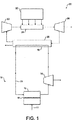
まず、図1に関して記載する。該図は、本発明の第1態様の方法を示す。浸透セル(または槽)12、原動機14(例えば、発電装置に連結しているタービン)および分離器16を含んで成る装置10を用いて、該方法を実施する。浸透セルは、半透膜18を含んで成る。
First, a description will be given with reference to FIG. The figure shows the method of the first aspect of the invention. The method is carried out using an
使用に際し、水11(例えば海水)を膜18の1つの側に導入する。30重量%の塩化ナトリウム溶液13を膜18の反対側に導入する。塩化ナトリウム溶液が、海水の全溶解固形物(TDS)濃度よりも高い塩化ナトリウム濃度を有するときに、浸透によって水が膜18を横切って流れる。膜18を横切る水の流入は、塩化ナトリウム溶液の圧力を増大させる。
In use, water 11 (eg seawater) is introduced on one side of the
加圧された塩化ナトリウム溶液を浸透セル12から除去して原動機14に導入する。溶液は浸透工程によって加圧されているため、塩化ナトリウム溶液のポンピングは必要ない。加圧された塩化ナトリウム溶液を用いて原動機14を駆動する。生じた機械エネルギーを、例えば、電気エネルギー等の他の形態のエネルギーに変換することができる。
The pressurized sodium chloride solution is removed from the
次いで、塩化ナトリウム溶液を原動機14から除去して分離器16に導入してよい。分離器16において、蒸発によって水を塩化ナトリウム溶液から除去する。塩化ナトリウム溶液から水を一旦除去すると、塩化ナトリウム溶液を再利用のために浸透セルにリサイクルする。従って、浸透工程において、塩化ナトリウム溶液を補充または置換するための新たな塩化ナトリウム溶液を必要としない。
The sodium chloride solution may then be removed from the
蒸発工程で除去された水を回収して、例えば飲料水等に用いてよい。このように、本発明のこの態様を用いて海水を脱塩することができる。 The water removed in the evaporation step may be recovered and used, for example, for drinking water. Thus, seawater can be desalted using this aspect of the invention.
装置10を、常套の発電装置22に近接して設置する。発電装置22は、ボイラー24、原動機26(スチームタービン)、およびサーマルユニット28(発電装置のコンデンサ)を含んで成る。
The
使用に際し、ポンプ30を介してボイラー24に水を導入する。燃料32の燃焼によりボイラー24で水を加熱して、過熱水蒸気を生成する。次いで、過熱水蒸気を高圧で原動機(スチームタービン)26に導入し、過熱水蒸気を用いて原動機26を駆動して機械エネルギーを発生させる。回転している原動機26の機械エネルギーを、例えば、電気エネルギー等の他の形態のエネルギーに変換することができる。
In use, water is introduced into the
次いで、飽和または過熱水蒸気を、原動機26から回収して、サーマルユニット28に導入する。サーマルユニットにおいて、水蒸気を水に凝縮する。水蒸気からの余剰熱を用いて、装置10の塩化ナトリウム溶液から水を蒸発させる。このように、装置10の原動機14からの塩化ナトリウム溶液を、発電装置22のサーマルユニット28において冷却剤として用いる。従って、装置10の分離器16は、発電装置22のサーマルユニット28と実質的に同一である。
Next, saturated or superheated steam is recovered from the
冷却したら、発電装置の凝縮水蒸気を、ポンプ30を介してボイラー24にリサイクルする。
After cooling, the condensed water vapor of the power generator is recycled to the
分離器16によって塩化ナトリウム溶液から除去した水蒸気または水を、純水生成物として用いることができ、またはユニット10にリサイクルすることができる。
The water vapor or water removed from the sodium chloride solution by the
次に、図2に関して記載する。該図は、本発明の第2態様の方法を示す。装置100を用いて該方法を実施する。装置100は、図1の装置10に類似しており、装置の同じコンポーネントには、同じ数字を付している。しかしながら、装置100は、冷涼な環境での使用に適合している。従って、図1の装置10と異なり、装置100は、晶析装置である分離器116を含んで成る。使用に際し、原動機14からの新たな溶液を分離器116に導入し、周囲温度によって冷却して、氷、および濃縮された塩化ナトリウム溶液を生成する。前者は除去して廃棄するが、後者は浸透セル12にリサイクルする。
Reference is now made to FIG. The figure shows the method of the second aspect of the invention. The method is performed using
次に、図3に関して記載する。該図は、本発明の第3態様の方法を示す。装置200を用いて該方法を実施する。装置200は、図1の装置10に類似しており、装置の同じコンポーネントには、同じ数字を付している。しかしながら、装置200は、暖かく乾燥した環境での使用に適合している。従って、図1の装置10と異なり、装置100は、自然の、または効果的な蒸発および/もしくは太陽エネルギーに依る分離器216を含んで成り、原動機14から生じた新たな溶液から溶媒を除去する。
Reference is now made to FIG. The figure shows the method of the third aspect of the invention. The method is performed using
Claims (21)
a)液体と液体よりも高い浸透ポテンシャルを有する溶液との間に選択膜を配置し、膜を横切る液体の流入により溶液を加圧状態にすること、
b)溶液において生じた圧力を、圧力交換システムを介して別の液体に伝達し、該別の液体に伝達された圧力を用いて原動機を駆動すること、
c)溶液を回収すること、
d)溶液から溶媒の少なくともいくらかを分離して残存生成物を生成すること、ならびに
e)工程d)の分離溶媒および/または残存生成物を工程a)にリサイクルすること
を含んで成る方法。A driving method of a prime mover,
a) placing a selective membrane between the liquid and a solution having a higher osmotic potential than the liquid and placing the solution in a pressurized state by the inflow of liquid across the membrane;
b) transferring the pressure generated in the solution to another liquid via a pressure exchange system and driving the prime mover with the pressure transferred to the other liquid ;
c) collecting the solution;
d) separating at least some of the solvent from the solution to produce a residual product; and e) recycling the separated solvent and / or residual product of step d) to step a).
i)溶液中の溶質の少なくともいくらかを結晶化するのに十分低いか、または
ii)溶媒を結晶化する溶媒の凝固点よりも下である
高所まで移動させて、低い溶質濃度を有する部分および高い溶質濃度を有する部分に溶液を分離する、請求項1〜16のいずれかに記載の方法。When the solution from step a) is at ambient temperature,
i) low enough to crystallize at least some of the solutes in the solution, or ii) move the solvent to a high point below the freezing point of the solvent to crystallize and have a portion with low solute concentration and high The method according to claim 1, wherein the solution is separated into portions having a solute concentration.
Applications Claiming Priority (3)
| Application Number | Priority Date | Filing Date | Title |
|---|---|---|---|
| GB0319042.8 | 2003-08-13 | ||
| GBGB0319042.8A GB0319042D0 (en) | 2003-08-13 | 2003-08-13 | Osmotic energy |
| PCT/GB2004/003450 WO2005017352A1 (en) | 2003-08-13 | 2004-08-11 | Osmotic energy |
Publications (3)
| Publication Number | Publication Date |
|---|---|
| JP2007533884A JP2007533884A (en) | 2007-11-22 |
| JP2007533884A5 JP2007533884A5 (en) | 2010-05-20 |
| JP4546473B2 true JP4546473B2 (en) | 2010-09-15 |
Family
ID=28052461
Family Applications (1)
| Application Number | Title | Priority Date | Filing Date |
|---|---|---|---|
| JP2006523048A Expired - Fee Related JP4546473B2 (en) | 2003-08-13 | 2004-08-11 | Penetrating energy |
Country Status (11)
| Country | Link |
|---|---|
| US (2) | US20060225420A1 (en) |
| EP (1) | EP1660772B9 (en) |
| JP (1) | JP4546473B2 (en) |
| CN (1) | CN1853044A (en) |
| AT (1) | ATE365867T1 (en) |
| AU (1) | AU2004265489B2 (en) |
| CY (1) | CY1107727T1 (en) |
| DE (1) | DE602004007274T4 (en) |
| ES (1) | ES2288261T3 (en) |
| GB (1) | GB0319042D0 (en) |
| WO (1) | WO2005017352A1 (en) |
Cited By (1)
| Publication number | Priority date | Publication date | Assignee | Title |
|---|---|---|---|---|
| US9863405B2 (en) | 2014-02-28 | 2018-01-09 | Kabushiki Kaisha Toshiba | Circulatory osmotic pressure electric power generation system and method, phase control method for working medium, and working medium for circulatory osmotic pressure electric power generation |
Families Citing this family (64)
| Publication number | Priority date | Publication date | Assignee | Title |
|---|---|---|---|---|
| US7608188B2 (en) | 2004-12-03 | 2009-10-27 | Board Of Regents Of The Nevada System Of Higher Education | Vacuum enhanced direct contact membrane distillation |
| US8083942B2 (en) | 2004-12-06 | 2011-12-27 | Board of Regents of the Nevada System of Higher Education, on Behalf of the Universary of Nevada, Reno | Systems and methods for purification of liquids |
| WO2007134226A1 (en) | 2006-05-12 | 2007-11-22 | Energy Recovery, Inc. | Hybrid ro/pro system |
| CN101489937B (en) * | 2006-06-08 | 2016-08-10 | 耶鲁大学 | Multi-stage column distillation (MSCD) method reclaimed for osmotic solute |
| US8029671B2 (en) | 2006-06-13 | 2011-10-04 | Board Of Regents Of The Nevada System Of Higher Education, On Behalf Of The University Of Nevada, Reno | Combined membrane-distillation-forward-osmosis systems and methods of use |
| CA2668720A1 (en) * | 2006-11-09 | 2008-05-22 | Yale University | Osmotic heat engine |
| US8562834B2 (en) * | 2007-02-27 | 2013-10-22 | Deka Products Limited Partnership | Modular assembly for a portable hemodialysis system |
| WO2009155683A1 (en) * | 2008-06-24 | 2009-12-30 | Saltworks Technologies Inc. | Method, apparatus and plant for desalinating saltwater using concentration difference energy |
| EA022856B1 (en) * | 2008-12-03 | 2016-03-31 | Оасис Уотер, Инк. | Utility scale osmotic grid storage |
| GB0822362D0 (en) * | 2008-12-08 | 2009-01-14 | Surrey Aquatechnology Ltd | Improved solvent removal |
| EP2417067A4 (en) * | 2009-04-09 | 2014-10-22 | Saltworks Technologies Inc | Method and system for desalinating saltwater using concentration difference energy |
| US8545701B2 (en) | 2009-08-18 | 2013-10-01 | Maher Isaac Kelada | Induced symbiotic osmosis [ISO] for salinity power generation |
| JP2011083663A (en) * | 2009-10-13 | 2011-04-28 | Fujifilm Corp | Water purification apparatus and method |
| US9044711B2 (en) | 2009-10-28 | 2015-06-02 | Oasys Water, Inc. | Osmotically driven membrane processes and systems and methods for draw solute recovery |
| BR112012010232A2 (en) | 2009-10-28 | 2017-07-04 | Oasys Water Inc | direct osmosis separation processes |
| US8695343B2 (en) * | 2009-12-04 | 2014-04-15 | General Electric Company | Economical and sustainable disposal of zero liquid discharge salt byproduct |
| US20110155666A1 (en) * | 2009-12-30 | 2011-06-30 | Chevron U.S.A. Inc. | Method and system using hybrid forward osmosis-nanofiltration (h-fonf) employing polyvalent ions in a draw solution for treating produced water |
| KR101200838B1 (en) | 2010-07-14 | 2012-11-13 | 한국기계연구원 | Apparatus and methods for electricity generation and water desalination |
| JP5595172B2 (en) * | 2010-08-09 | 2014-09-24 | 三菱重工業株式会社 | Concentration difference power generator |
| JP2012041849A (en) * | 2010-08-18 | 2012-03-01 | Mitsubishi Heavy Ind Ltd | Concentration difference power generation system |
| RU2457338C2 (en) * | 2010-08-26 | 2012-07-27 | Игорь Анатольевич Ревенко | Conversion method of heat energy to mechanical energy, method for increasing enthalpy and compression coefficient of water vapour |
| WO2012067689A1 (en) * | 2010-10-27 | 2012-05-24 | Modine Manufacturing Company | Rankine cycle system and method |
| KR101174281B1 (en) | 2010-12-09 | 2012-08-20 | 두산중공업 주식회사 | Hybrid system for forward osmosis desalination and co2 capture using exhaust gas |
| WO2012105123A1 (en) * | 2011-02-02 | 2012-08-09 | 理研ビタミン株式会社 | Method for processing seafood extract, seafood extract, food and drink |
| JP5575015B2 (en) * | 2011-03-07 | 2014-08-20 | 株式会社日立製作所 | Fresh water production system |
| SG194156A1 (en) * | 2011-04-25 | 2013-11-29 | Trevi Systems Inc | Recovery of retrograde soluble solute for forward osmosis water treatment |
| CN103582520A (en) * | 2011-06-08 | 2014-02-12 | 日东电工株式会社 | Forward osmosis membrane flow system and composite semipermeable membrane for forward osmosis membrane flow system |
| ITAN20110123A1 (en) * | 2011-09-09 | 2013-03-10 | Asteria Per Lo Sviluppo Tecnologico E Per La Ricer | DIRECT OSMOSIS PROCEDURE FOR THE CONTINUOUS CYCLE PRODUCTION OF ELECTRICITY. |
| US9103232B1 (en) | 2012-02-28 | 2015-08-11 | Joseph Hall | Steam condenser |
| KR101318331B1 (en) * | 2012-03-16 | 2013-10-16 | 한국에너지기술연구원 | Concentration gradient power production device using flow electrode |
| KR101245264B1 (en) | 2012-03-27 | 2013-03-19 | 한국기계연구원 | Method of capturing including method for desalination of saltwater using forward osmosis and hybrid system of capturing carbon dioxide-forward osmosis |
| CN102661181A (en) * | 2012-04-25 | 2012-09-12 | 北京亿玮坤节能科技有限公司 | Novel power generating working medium |
| WO2013164541A2 (en) * | 2012-05-02 | 2013-11-07 | Total Sa | Power generation by direct osmosis |
| US20130340745A1 (en) * | 2012-06-26 | 2013-12-26 | Sanza Kazadi | Membrane-enabled heat pipe |
| JP5996337B2 (en) * | 2012-09-05 | 2016-09-21 | 株式会社東芝 | Forward osmosis water production system |
| US8974668B2 (en) | 2013-02-15 | 2015-03-10 | Maher Isaac Kelada | Hollow fiber membrane element and methods of making same |
| KR101489855B1 (en) * | 2013-02-22 | 2015-02-06 | 지에스건설 주식회사 | Desalination system capable of recovering osmotic energy and method thereof |
| GB2499740B (en) * | 2013-04-19 | 2015-09-16 | Ide Technologies Ltd | Osmosis apparatus |
| CN105308317A (en) * | 2013-05-08 | 2016-02-03 | 韩国能源技术研究院 | Large-capacity electric power storage system using thermal energy/chemical potential |
| JP2015098833A (en) * | 2013-11-19 | 2015-05-28 | 株式会社東芝 | Cyclic osmotic power generation system and work medium |
| CN103615363B (en) * | 2013-11-23 | 2016-06-22 | 华中科技大学 | A kind of salt error energy TRT and method |
| CN103603764B (en) * | 2013-11-23 | 2016-04-13 | 华中科技大学 | Salt error energy classification power generation system and method |
| CN103771564B (en) * | 2014-02-19 | 2015-05-20 | 集美大学 | Ocean thermal energy open circulation joint deep sea reverse-osmosis seawater desalination system |
| US10100816B2 (en) * | 2014-09-08 | 2018-10-16 | Applied Biomimetic A/S | Electricity generation process |
| WO2016072461A1 (en) * | 2014-11-07 | 2016-05-12 | 株式会社 東芝 | Water treatment method, water treatment system, and water treatment device |
| DE102015200250A1 (en) * | 2015-01-12 | 2016-07-14 | Siemens Aktiengesellschaft | Method for operating an osmotic power plant and osmotic power plant |
| US10009297B2 (en) * | 2015-03-12 | 2018-06-26 | International Business Machines Corporation | Entity metadata attached to multi-media surface forms |
| CN104694085A (en) * | 2015-03-22 | 2015-06-10 | 吴新祥 | Thermotechnical working medium |
| JP2017025834A (en) * | 2015-07-24 | 2017-02-02 | 東洋紡株式会社 | Forward osmotic power generation method, and forward osmotic power generation system used therefor |
| JP2017032225A (en) * | 2015-08-03 | 2017-02-09 | 株式会社東芝 | Humidification device and air-conditioning device |
| CN105042677B (en) * | 2015-08-24 | 2017-11-28 | 华北电力大学 | A kind of heating plant and heat supply method of solar energy antigravity Natural Circulation |
| JP6517683B2 (en) * | 2015-12-21 | 2019-05-22 | 株式会社東芝 | Water treatment system and working medium used for water treatment system |
| WO2017125877A1 (en) | 2016-01-20 | 2017-07-27 | King Abdullah University Of Science And Technology | Method of osmotic energy harvesting using responsive compounds and molecules |
| GB201605068D0 (en) * | 2016-03-24 | 2016-05-11 | Applied Biomimetic As | Electricity generation process |
| GB201605070D0 (en) | 2016-03-24 | 2016-05-11 | Applied Biomimetic As | Power generation process |
| JP2018118186A (en) * | 2017-01-23 | 2018-08-02 | 株式会社東芝 | Forward osmosis membrane and water treatment system |
| GB201711238D0 (en) | 2017-07-12 | 2017-08-23 | Saltkraft Aps | Power generation process |
| GB201711240D0 (en) | 2017-07-12 | 2017-08-23 | Saltkraft Aps | Power generation process |
| CN109426290B (en) * | 2017-09-05 | 2021-12-07 | 韩国能量技术研究院 | Energy self-sufficient type intelligent farm system based on salt difference power generation |
| CN109470070A (en) * | 2017-09-08 | 2019-03-15 | 东南大学 | A kind of preparation of Lewis acid-base adducts object saturated solution and decomposition technique and its application |
| CN110513167B (en) * | 2019-08-27 | 2022-05-13 | 中国科学院广州能源研究所 | Heat and mass mixed multistage power generation system |
| US11092141B1 (en) | 2020-06-19 | 2021-08-17 | James Cheng-Shyong Lu | Method and system for generating large-scale renewable energy by pressure-enhanced osmosis and synergistic effects |
| JP7521297B2 (en) | 2020-07-22 | 2024-07-24 | 株式会社Ihi | Concentration Difference Power Generation System |
| DE102022119377A1 (en) * | 2022-08-02 | 2024-02-08 | Georg Béla Husz | SALT POWER PLANT |
Family Cites Families (13)
| Publication number | Priority date | Publication date | Assignee | Title |
|---|---|---|---|---|
| US3587227A (en) * | 1969-06-03 | 1971-06-28 | Maxwell H Weingarten | Power generating means |
| US3825122A (en) * | 1973-06-11 | 1974-07-23 | J Taylor | Reverse-osmosis pump |
| US3906250A (en) * | 1973-07-03 | 1975-09-16 | Univ Ben Gurion | Method and apparatus for generating power utilizing pressure-retarded-osmosis |
| US3978344A (en) * | 1973-11-12 | 1976-08-31 | Jellinek Hans H G | Osmosis process for producing energy |
| US4177146A (en) * | 1975-05-05 | 1979-12-04 | Camirand Wayne M | Methods and apparatus for continuously endowing liquid with mechanical energy by osmosis |
| IL51541A (en) * | 1977-02-25 | 1979-05-31 | Univ Ben Gurion | Method and apparatus for generating power utilizing pressuure retarded osmosis |
| DE3121968A1 (en) * | 1981-06-03 | 1983-01-05 | Otto 2000 Hamburg Grönecke | Method for producing a pressure differential in a fluid and system for implementing the method |
| JPS5853684A (en) * | 1981-09-28 | 1983-03-30 | Kajima Corp | Power generating method utilizing penetration pressure |
| EP0298097B1 (en) * | 1987-01-05 | 1992-08-12 | HAUGE, Leif J. | Pressure exchanger for liquids |
| US5238574A (en) * | 1990-06-25 | 1993-08-24 | Kawasaki Jukogyo Kabushiki Kaisha | Method and apparatus having reverse osmosis membrane for concentrating solution |
| US6185940B1 (en) * | 1999-02-11 | 2001-02-13 | Melvin L. Prueitt | Evaporation driven system for power generation and water desalinization |
| NO312563B1 (en) | 2000-04-11 | 2002-05-27 | Energy Recovery Inc | Method of reducing noise and cavitation in a pressure exchanger which increases or decreases the pressure of fluids by the displacement principle, and such a pressure exchanger |
| US6539718B2 (en) * | 2001-06-04 | 2003-04-01 | Ormat Industries Ltd. | Method of and apparatus for producing power and desalinated water |
-
2003
- 2003-08-13 GB GBGB0319042.8A patent/GB0319042D0/en not_active Ceased
-
2004
- 2004-08-11 DE DE602004007274T patent/DE602004007274T4/en not_active Expired - Lifetime
- 2004-08-11 US US10/568,082 patent/US20060225420A1/en not_active Abandoned
- 2004-08-11 WO PCT/GB2004/003450 patent/WO2005017352A1/en active IP Right Grant
- 2004-08-11 JP JP2006523048A patent/JP4546473B2/en not_active Expired - Fee Related
- 2004-08-11 CN CN200480026502.6A patent/CN1853044A/en active Pending
- 2004-08-11 ES ES04743686T patent/ES2288261T3/en not_active Expired - Lifetime
- 2004-08-11 AT AT04743686T patent/ATE365867T1/en not_active IP Right Cessation
- 2004-08-11 EP EP04743686A patent/EP1660772B9/en not_active Expired - Lifetime
- 2004-08-11 AU AU2004265489A patent/AU2004265489B2/en not_active Ceased
-
2007
- 2007-09-04 CY CY20071101145T patent/CY1107727T1/en unknown
-
2008
- 2008-09-29 US US12/285,046 patent/US8099958B2/en not_active Expired - Fee Related
Cited By (1)
| Publication number | Priority date | Publication date | Assignee | Title |
|---|---|---|---|---|
| US9863405B2 (en) | 2014-02-28 | 2018-01-09 | Kabushiki Kaisha Toshiba | Circulatory osmotic pressure electric power generation system and method, phase control method for working medium, and working medium for circulatory osmotic pressure electric power generation |
Also Published As
| Publication number | Publication date |
|---|---|
| EP1660772B9 (en) | 2010-03-03 |
| CN1853044A (en) | 2006-10-25 |
| ATE365867T1 (en) | 2007-07-15 |
| US20090091139A1 (en) | 2009-04-09 |
| JP2007533884A (en) | 2007-11-22 |
| DE602004007274D1 (en) | 2007-08-09 |
| GB0319042D0 (en) | 2003-09-17 |
| AU2004265489A1 (en) | 2005-02-24 |
| CY1107727T1 (en) | 2013-04-18 |
| EP1660772B1 (en) | 2007-06-27 |
| US20060225420A1 (en) | 2006-10-12 |
| AU2004265489B2 (en) | 2010-09-02 |
| EP1660772A1 (en) | 2006-05-31 |
| US8099958B2 (en) | 2012-01-24 |
| DE602004007274T2 (en) | 2008-02-28 |
| ES2288261T3 (en) | 2008-01-01 |
| DE602004007274T4 (en) | 2010-09-30 |
| WO2005017352A1 (en) | 2005-02-24 |
Similar Documents
| Publication | Publication Date | Title |
|---|---|---|
| JP4546473B2 (en) | Penetrating energy | |
| US8221629B2 (en) | Solvent removal process | |
| AU2007310694B2 (en) | Separation process | |
| US5405503A (en) | Process for desalinating water while producing power | |
| US20100192575A1 (en) | Process and systems | |
| US20170136414A1 (en) | Water treatment method, water treatment system, and water treatment apparatus | |
| JP5943924B2 (en) | Osmotic pressure driven membrane process and system, and extraction solute recovery method | |
| Ahmed et al. | Assessment of pilot scale forward osmosis system for Arabian Gulf seawater desalination using polyelectrolyte draw solution | |
| Sahith et al. | Technologies in desalination | |
| JP2013167156A (en) | Fluid membrane separation power generation system | |
| US11840462B2 (en) | Switchable system for high-salinity brine desalination and fractional precipitation | |
| WO2022034353A1 (en) | Solvent extraction water treatment process for wide range of salinity with no liquid waste discharge | |
| Patel et al. | A Review on Seawater Desalination Technology and Concentrating Solar Power | |
| Gladea et al. | Water Desalination Technology Map– | |
| Chudnovsky et al. | Integrated Wastewater Recovery and Reuse via Waste Heat Utilization | |
| El-Hadad et al. | A new Solar Technology Technique for Wastewater and Seawater Treatment |
Legal Events
| Date | Code | Title | Description |
|---|---|---|---|
| A711 | Notification of change in applicant |
Free format text: JAPANESE INTERMEDIATE CODE: A711 Effective date: 20070910 |
|
| A521 | Request for written amendment filed |
Free format text: JAPANESE INTERMEDIATE CODE: A821 Effective date: 20070910 |
|
| A131 | Notification of reasons for refusal |
Free format text: JAPANESE INTERMEDIATE CODE: A131 Effective date: 20091222 |
|
| A601 | Written request for extension of time |
Free format text: JAPANESE INTERMEDIATE CODE: A601 Effective date: 20100323 |
|
| A602 | Written permission of extension of time |
Free format text: JAPANESE INTERMEDIATE CODE: A602 Effective date: 20100330 |
|
| A524 | Written submission of copy of amendment under article 19 pct |
Free format text: JAPANESE INTERMEDIATE CODE: A524 Effective date: 20100401 |
|
| TRDD | Decision of grant or rejection written | ||
| A01 | Written decision to grant a patent or to grant a registration (utility model) |
Free format text: JAPANESE INTERMEDIATE CODE: A01 Effective date: 20100601 |
|
| A01 | Written decision to grant a patent or to grant a registration (utility model) |
Free format text: JAPANESE INTERMEDIATE CODE: A01 |
|
| A61 | First payment of annual fees (during grant procedure) |
Free format text: JAPANESE INTERMEDIATE CODE: A61 Effective date: 20100701 |
|
| FPAY | Renewal fee payment (event date is renewal date of database) |
Free format text: PAYMENT UNTIL: 20130709 Year of fee payment: 3 |
|
| R150 | Certificate of patent or registration of utility model |
Ref document number: 4546473 Country of ref document: JP Free format text: JAPANESE INTERMEDIATE CODE: R150 Free format text: JAPANESE INTERMEDIATE CODE: R150 |
|
| R250 | Receipt of annual fees |
Free format text: JAPANESE INTERMEDIATE CODE: R250 |
|
| R250 | Receipt of annual fees |
Free format text: JAPANESE INTERMEDIATE CODE: R250 |
|
| R250 | Receipt of annual fees |
Free format text: JAPANESE INTERMEDIATE CODE: R250 |
|
| R250 | Receipt of annual fees |
Free format text: JAPANESE INTERMEDIATE CODE: R250 |
|
| R250 | Receipt of annual fees |
Free format text: JAPANESE INTERMEDIATE CODE: R250 |
|
| R250 | Receipt of annual fees |
Free format text: JAPANESE INTERMEDIATE CODE: R250 |
|
| R250 | Receipt of annual fees |
Free format text: JAPANESE INTERMEDIATE CODE: R250 |
|
| LAPS | Cancellation because of no payment of annual fees |