JP4545365B2 - Coriolis flowmeter for large flow with reduced dimensions - Google Patents
Coriolis flowmeter for large flow with reduced dimensions Download PDFInfo
- Publication number
- JP4545365B2 JP4545365B2 JP2001535011A JP2001535011A JP4545365B2 JP 4545365 B2 JP4545365 B2 JP 4545365B2 JP 2001535011 A JP2001535011 A JP 2001535011A JP 2001535011 A JP2001535011 A JP 2001535011A JP 4545365 B2 JP4545365 B2 JP 4545365B2
- Authority
- JP
- Japan
- Prior art keywords
- flow
- attached
- outlet
- pipe
- coriolis
- Prior art date
- Legal status (The legal status is an assumption and is not a legal conclusion. Google has not performed a legal analysis and makes no representation as to the accuracy of the status listed.)
- Expired - Fee Related
Links
Images


Classifications
-
- G—PHYSICS
- G01—MEASURING; TESTING
- G01F—MEASURING VOLUME, VOLUME FLOW, MASS FLOW OR LIQUID LEVEL; METERING BY VOLUME
- G01F1/00—Measuring the volume flow or mass flow of fluid or fluent solid material wherein the fluid passes through a meter in a continuous flow
- G01F1/76—Devices for measuring mass flow of a fluid or a fluent solid material
- G01F1/78—Direct mass flowmeters
- G01F1/80—Direct mass flowmeters operating by measuring pressure, force, momentum, or frequency of a fluid flow to which a rotational movement has been imparted
- G01F1/84—Coriolis or gyroscopic mass flowmeters
- G01F1/8409—Coriolis or gyroscopic mass flowmeters constructional details
- G01F1/8413—Coriolis or gyroscopic mass flowmeters constructional details means for influencing the flowmeter's motional or vibrational behaviour, e.g., conduit support or fixing means, or conduit attachments
-
- G—PHYSICS
- G01—MEASURING; TESTING
- G01F—MEASURING VOLUME, VOLUME FLOW, MASS FLOW OR LIQUID LEVEL; METERING BY VOLUME
- G01F1/00—Measuring the volume flow or mass flow of fluid or fluent solid material wherein the fluid passes through a meter in a continuous flow
- G01F1/76—Devices for measuring mass flow of a fluid or a fluent solid material
- G01F1/78—Direct mass flowmeters
- G01F1/80—Direct mass flowmeters operating by measuring pressure, force, momentum, or frequency of a fluid flow to which a rotational movement has been imparted
- G01F1/84—Coriolis or gyroscopic mass flowmeters
- G01F1/845—Coriolis or gyroscopic mass flowmeters arrangements of measuring means, e.g., of measuring conduits
- G01F1/8468—Coriolis or gyroscopic mass flowmeters arrangements of measuring means, e.g., of measuring conduits vibrating measuring conduits
- G01F1/8472—Coriolis or gyroscopic mass flowmeters arrangements of measuring means, e.g., of measuring conduits vibrating measuring conduits having curved measuring conduits, i.e. whereby the measuring conduits' curved center line lies within a plane
- G01F1/8477—Coriolis or gyroscopic mass flowmeters arrangements of measuring means, e.g., of measuring conduits vibrating measuring conduits having curved measuring conduits, i.e. whereby the measuring conduits' curved center line lies within a plane with multiple measuring conduits
Description
【0001】
【技術分野】
本発明はコリオリ流量計に関する。より詳細には、本発明は実質的に半円形の弧を有する流管と1組の受けバーとを用いることによってコリオリ流量計のフラッグ寸法を小さくすることに関する。さらに詳細には、本発明はゼロ安定性を維持し振動する流管の振幅を減少させて受けバーに加わる応力を減少さる構成部分の形状に関する。
【0002】
【技術的問題】
1985年1月1日にJ.E.スミスらに対して発行された米国特許第4491025号及び1982年2月11日のJ.E.スミスへの再発行特許第31450号に開示されるように、配管を通って流れる物質の質量流量及び他の情報を測定するためにコリオリ効果の質量流量計を用いることが知られている。これらの流量計は曲線状の1本またはそれより多くの流管を有する。コリオリ質量流量計における各々の流管の形状は、単純な曲げ捩れの型あるいは結合型の1組の固有振動モードを有する。物質を充填された振動系の固有振動モードは部分的には流管と流管内の物質との併せた質量によって決定される。物質は連結された配管から流量計の入口側に流入する。それから物質は1本または複数本の流管を通って流れ、出口側で流量計から連結された配管に出てゆく。
【0003】
流管を所望の振動モードで振動させるため駆動源が流管に力を加える。典型的には所望の振動モードは第1の位相が外れた曲げモードである。流管を通って物質が流れない時に、流管上の全ての点は一致した位相で振動する。物質が流れ始めると、コリオリ加速度により流管上の各点が流管上の他の点に対して異なる位相を有するようになる。流管の入口側の位相は駆動源より遅れるが、出口側の位相は駆動源より進む。流管の運動を表す正弦波信号を生ずるように流管に検出器が配置される。2つの検出器の信号の間の位相差は1本または複数本の流管を通って流れる物質の質量流量に比例する。そのから検出器に連結された電子回路部分は物質の質量流量及び他の特性を決定するため信号の振動数及び位相差を用いる。
【0004】
コリオリ流量計が他の質量流量計に対して有する利点は、流量計が典型的には計算された物質の質量流量における誤差が0.1%より小さくなることである。オリフィス流量計、タービン流量計、渦流量計等の他の従来の型の質量流量測定装置は、典型的には流量測定において0.5%またはそれ以上の誤差を有する。コリオリ質量流量計は他の型の質量流量測定装置より精度が高いけれども、コリオリ流量計はまた製造により多くの経費がかかる。流量計の利用者は精度より経費の節約を選んでより経費の少ない型の流量計を選択することが多い。それゆえコリオリ流量計の製造者は、他の質量流量測定装置に匹敵する製品を製造するため、製造の経費が少なく、実際の質量流量の0.5%以内の精度で質量流量を決定するコリオリ流量計を望んでいる。
【0005】
コリオリ流量計が他の装置より経費を要する1つの理由は、流管に加わる多くの望ましくない振動を減少させる部品が必要なことである。1つのこのような部品として流管を配管に取り付けるマニホルドがある。2本管式コリオリ流量計において、マニホルドはまた配管から受け入れた物質の流れを2つの別個の流れに分割しその流れを別個の流管に向ける。配管に連結されたポンプ等の外的要因によって生ずる振動を減少させるために、マニホルドは振動を吸収するのに十分な剛性を有していなければならない。多くの従来のマニホルドは十分な質量を有するように鋳造金属で形成されている。さらに入口側マニホルドと出口側マニホルドとの間隔を維持するマニホルド間のスペーサがある。このスペーサはまた外部の力が流管を振動させないようにするために金属あるいは他の剛性の材料で形成される。これらの鋳造物を形成するために用いられる多量の金属のため流量計の製造経費が増大する。しかしながら望ましくない振動をなくすことにより流量計の精度が非常に高まる。
【0006】
コリオリ流量計の当業者にとって第2の問題は、流量計がある種の用途に用いられるのに大きすぎるフラッグ寸法を有することである。これを論ずる場合、フラッグ寸法は流管が配管から外方に延びる長さである。空間が制限されたり高価になる環境がある。典型的なフラッグ寸法を有する流量計はこの制限された面積には適合しないであろう。
【0007】
大きい流量を扱うコリオリ流量計においてフラッグ寸法を減少させることが特に問題になる。これを論ずる場合、大きい流量は318kg/分(700lbs./分)またはそれ以上である。より大きい流量を扱う流量計においてフラッグ寸法を減少させることが問題になる1つの理由は、流管がより大きい径にならなければならないことである。より大きい径の流管はより小さい径の流管より高い駆動振動数を有し、フラッグ寸法を減少させると設計がより難しくなる。より大きい径の流管はまたより小さいフラツグ寸法になった時にゼロ安定性の問題を生ずる。これらの理由により、大きい流量を扱うことができる2本管式コリオリ流量計を製造することは特に問題になる。
【0008】
【解決手段】
前述した、また他の問題は、本発明において減少したフラッグ寸法を有するコリオリ流量計を提供することにより解決され、技術的進歩がなされる。本発明のコリオリ流量計は大きい質量流量を扱うことができる流管を有する。本発明のコリオリ流量計は従来のマニホルド及びスペーサを有していず、その代りにスペーサが実質的にマニホルドを取り囲んでいる。この形状は流量計の製造経費を減少させる。本発明のコリオリ流量計はまた減少したフラッグ寸法を有するが、それにより空間が高価になり従来のフラッグ寸法を有するコリオリ流量計を用いることができない領域で本発明のコリオリ流量計が用いられるようになる。
【0009】
流管を入口側端部と出口側端部との間で実質的に半円形の弧となるように形成することによって流管のフラッグ寸法が減少する。半円形の弧により流管の隆起が減少しフラッグの高さが減少する。流量計の精度を高めるため、半円形の弧の全長が振動しなければならない。
【0010】
流管の入口側端部と出口側端部とを含む平面に実質的に垂直な各々の流管の半円形の弧上の位置で流管に駆動源が取り付けられる。駆動源は流管を振動させるように駆動源によって流管に加わるエネルギーの量を最大にするためこの位置に配置される。駆動源が流管を低い振幅で振動させて流管に取り付けられた受けバーに加わる応力を減少させるようにするため駆動源に駆動信号が供給される。
【0011】
流管が振動する際に流管の振動モードを分離するため、第1の受けバーが流管の入口側端部近くに取り付けられ、第2の受けバーが流管の出口側端部近くに取り付けられる。受けバーは流管の実質的に同じ位置で各々の流管に取り付けられた金属製の部分である。
【0012】
振動する流管におけるコリオリ力を検出するため、ピックオフセンサーが低い振幅の振動での最大のコリオリ力の大きさを検出できるようにする位置で流管に取り付けられなければならない。これにより受けバーに加わる応力を減少させるために低い振幅の振動が用いられるようになる。
【0013】
流管を配管に連結するように入口側のマニホルド及び出口側のマニホルドが流管の入口側及び出口側の端部に取り付けられよう。各々のマニホルドは材料の経費を減少させるため別個に鋳造された別個の部分である。各々のマニホルドは半円形の弧状の入口側及び出口側の端部を配管に連結するように実質的に90°屈曲する流路を有するであろう。
【0014】
マニホルドの間の距離を維持するために各々のマニホルドにスペーサが取り付けられる。このスペーサは4つの辺を有していて対向する端側が入口側及び出口側のマニホルドに取り付けられる。スペーサは中空の空所を包囲している。これによりマニホルドとスペーサーとの両方の鋳造に用いられる材料の量が減少する。スペーサの上側の開口によりマニホルドがスペーサから外方に突出する半円形弧状の流管に連結させられるようになる。
【0015】
流管を包囲するようにスペーサの上側にケーシングが取り付けられよう。このケーシングが振動する流管の振動数に近い振動数で共振することが問題になる。これは流管を通って流れる物質の特性の読み取りに誤差を与えることになろう。ケーシングの共振振動数を変えるために、ケーシングに質量体が取り付けられてケーシングの共振振動数を変化させることになろう。
前述の、また他の特徴は、以下の詳細な説明及び添付の図面から理解される。
【0016】
【図1のコリオリ流量計全体】
図1は流量計10及び流量計電子回路20からなるコリオリ流量計5を示している。流量計電子回路20は線路26を通じて密度、質量流量、全質量、温度及び他の情報を与えるようにリード線100を介して流量計センサー10に連結されている。本発明は駆動源の数、ピックオフセンサーの数、振動の動作モードにかかわらずいずれの型のコリオリ流量計にも用いられることが当業者にわかるであろう。さらに本発明は、物質が流管を通って流れる際にコリオリ効果を測定するため2本の流管103A−103Bを振動させ、それから物質の特性を測定するためコリオリ効果を用いるいすれのシステムにも用いられよう。
【0017】
流量計センサー10は1対のフランジ101及び101′、マニホルド102―102′、流管103A及び103B、受けバー120−121、駆動源104、及びピックオフセンサー105及び105′を含む。フランジ101−101′はマニホルド102−102′に取り付けられている。マニホルド102−102′は流管103A−103Bの対向する端部に取り付けられている。後述するように流管103A−103Bに受けバー120―121が取り付けられている。駆動源104は流管103A−103Bを相互に反対の方向に振動させられる位置で流管103A−103Bに取り付けられている。流管103A−103Bの対向する端部に、その位置での振動の位相差を検出するようにピックオフセンサー105−105′が取り付けられている。
【0018】
フランジ101及び101′がマニホルド102−102′に取り付けられ流管103A及び103Bを配管(図示せず)に連結している。流量計センサー10が測定される物質を移送する配管系(図示せず)に挿入されると、物質が入口側フランジ101を通って流量計センサー10に入り、全体の量の物質が入口側マニホルド102によって2つの流れに分割され、等量ずつ流管103A及び103Bに入るように向けられる。それから物質は出口側フランジ101′を通って流れ、ここで流量計センサー10を出てゆく。マニホルド102及び102′は最少の量の材料で形成される。
【0019】
流管103A及び103Bはそれぞれの曲げ軸W−W及び曲げ軸W′−W′を中心として実質的に同じ質量分布、慣性モーメント、弾性計数を有するように選択されて入口側マニホルド102及び出口側マニホルド102′に適切に装着されている。流管は実質的に平行になってマニホルドから外方に突出する。
【0020】
流管103A−103Bはそれぞれの曲げ軸W−W及び曲げ軸W′−W′を中心として位相が逆になって、流量計の第1の位相の外れた曲げモードという状態になるようにして駆動源104によって駆動される。駆動源104は流管103Aに装着されたマグネット及び流管103Bに装着された対向するコイルのような多くの周知の装置の1つからなるものでもよい。両方の流管103A−103Bを振動させるように対向するコイルに交流電流が流れる。流量計の電子回路20によってリード線130A−130Bを介して駆動源104に適当な駆動信号が供給される。図1の説明は単にコリオリ流量計の動作の一例としてなされたものであり、本発明の考え方を制限するものではない。
【0021】
流量計電子回路20はそれぞれリード線111及び111′に生ずる右及び左の速度信号を受け取る。流量計電子回路20はまた駆動源104に流管103A及び103Bを振動させる駆動信号をリード線110に与える。本発明はここに説明したように複数の駆動源に対して複数の駆動信号を与えることができる。流量計電子回路20は左及び右の速度信号を処理して質量流量を計算する。線路26は流量計電子回路20が操作者とのインタフェースをとれるようにする入出力手段を与える。流量計電子回路20の内部構成部分は従来のものである。それゆえ簡略にするため、流量計電子回路の完全な説明は省略される。
【0022】
コリオリ流量計センサー10の形状により実際の質量流量の5%以内の読み取り精度を維持しながら流管103A−103Bがより小さいフラッグ寸法を有することができるようになる。フラッグ寸法は流管のループがそのループに垂直で連結されている配管を含む面から外方に突出する長さである。コリオリ流量計センサ10の形状の第2の利点はより経費の少ないマニホルド及びスペーサが用いられることである。
【0023】
フラッグ寸法を減少させるために、流管103A−103Bは入口端部151−151′と出口側端部152−152′との間に実質的に半円形の弧150−150′を有する。実質的に半円形の弧150−150′は流管103A−103Bに連続的な曲線を形成することによってフラッグ寸法を減少させる。流管103A−103Bがコリオリ流量計5を通って大きい流量の物質を流れ易くするのに十分な直径とするこができるように実質的に半円形の弧150を用いなければならない。流管103A−103Bを配管に直列状に連結するために、入口側マニホルド102及び出口側マニホルド102′は流れを配管から実質的に半円形の弧150−150′に向けるように流路内で実質的に90°の屈曲部を有するであろう。
【0024】
ゼロ安定性を達成し流管103A−103Bの振動モードを分離するために、流管103A及び103Bに第1の受けバー120及び第2の受けバー121が取り付けられる。第1の受けバー120は流管103A−103Bの振動を制御するように流管103A及び103Bを連結するため流管103A−103Bにその入口側端部の近くで取り付けられる。第2の受けバー121は流管103A−103Bの振動を制御するように流管103A及び103Bを連結するため流管103A−103Bにその出口側端部の近くで取り付けられる。好ましい実施例において、第1の受けバー120及び第2の受けバー121は流管103A−103Bに、実質的に半円形の弧150上で相互に実質的に180°離れて取り付けられる。
【0025】
駆動源104は流管入103A−103Bの入口側151と出口側152との実質的に中心点となる半円形の弧150上の位置で流管103A−103Bに取り付けられる。この位置は駆動源104が最小量の電力を用いて流管103A−103Bに最大の力を与えられるようにするものである。駆動源104は所望の振幅及び振動数で振動できるようにする流量計電子回路20からの信号を線路110を介して受け取る。好ましい実施例において、振動の振動数は従来のコリオリ流量計より高い振動数となる流管103A−103Bの第1の位相の外れた曲げモードと実質的に同等である。より高い振動数からの応力を減少させるために、好ましい実施例において小さい振動振幅を維持するのが望ましい。
【0026】
流管103A−103Bを高い振動数及び及び小さい振幅で振動させるために、ピックオフセンサー105−105′が流管103A−103Bに、その最大量の振動が検出される位置に取り付けられなければならない。これによりピックオフセンサー105−105′が流れる物質によって生ずる最大量のコリオリ力の効果を検出することができるようになる。好ましい実施例において、ピックオフセンサーは軸W−W、軸W′−W′から実質的に30°の位置に配置されよう。しかしながら、流量計を駆動するために従来の電子回路が用いられる時にピックオフセンサーは軸W−W′から25°と50°との間のいずれの位置に配置されてもよい。
【0027】
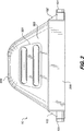
【図2のマニホルド102及び102′に取り付けられたスペーサ】
図2は流量計センサー10に取り付けられたスペーサ200を示している。スペーサ200は入口側マニホルド102と出口側マニホルド102′との間に一定の間隔を維持する。コリオリ流量計における従来のスペーサと異なって、スペーサは最少の材料で形成される。スペーサ200は対向する側に方形の端部190−191を有する。好ましい実施例において、方形の端部190−191はマニホルド102−102′における方形の板として鋳造される。壁部201−202によって表される4つの壁部が方形の台部190−191の各々の縁部を連結して包囲体を形成する。開口210により流管103A−103Bの実質的に半円形の弧150−150′がスペーサ200から突出できるようになる。
【0028】
【図3の流管103A−103Bのケーシング】
図3は流管103A−103B(図1に示される)を包囲するケーシング300を示している。ケーシング300は流管103A−103B上に嵌合して溶接あるいはボルト及びナット等の手段によってスペーサ200に取り付けられた中空の内側になった構造体である。
【0029】
ケーシング300は流管103A−103Bの所望の振動モードの振動数に実質的に等しい振動数で共振するであろう。この場合には、流管103A−103Bの振動の読み違いを防止するためにケーシング300の共振振動数を変えるのが望ましい。1つの解決策はケーシング300の実質的に平坦な部分302に重り301を取り付けることである。重りはケーシング300の一部として付加されることが当業者にはわかるであろう。
【0030】
前述したのは最少のフラッグ寸法を有するコリオリ流量計についての説明である。本発明の範囲に文言上、あるいは均等的に入る他の形のコリオリ流量計とすることができるのが当業者にはわかるであろう。
【図面の簡単な説明】
【図1】 減少したフラッグ寸法を有するコリオリ流量計を示す部である。
【図2】 スペーサに取り付けられた本発明のコリオリ流量計を示す図である。
【図3】 スペーサに取り付けられケーシングに包囲されたコリオリ流量計を示す図である。[0001]
【Technical field】
The present invention relates to a Coriolis flow meter. More particularly, the present invention relates to reducing the flag size of a Coriolis flow meter by using a flow tube having a substantially semi-circular arc and a set of receiving bars. More particularly, the present invention relates to the shape of the component that maintains zero stability and reduces the amplitude of the vibrating flow tube to reduce the stress applied to the receiving bar.
[0002]
[Technical issues]
On January 1, 1985, J.M. E. U.S. Pat. No. 4,491,025 issued to Smith et al. E. It is known to use a Coriolis effect mass flow meter to measure the mass flow rate and other information of substances flowing through piping, as disclosed in Smith Reissue Patent No. 31450. These flow meters have one or more curved flow tubes. The shape of each flow tube in a Coriolis mass flow meter has a set of natural vibration modes of simple bending torsional type or coupled type. The natural mode of vibration of a vibrating system filled with material is determined in part by the combined mass of the flow tube and the material in the flow tube. The substance flows from the connected pipe to the inlet side of the flow meter. The material then flows through one or more flow tubes and exits on the outlet side from a flow meter to a connected pipe.
[0003]
A drive source applies force to the flow tube to vibrate the flow tube in the desired vibration mode. The desired vibration mode is typically a bending mode out of the first phase. When no material flows through the flow tube, all points on the flow tube vibrate in phase. As material begins to flow, Coriolis acceleration causes each point on the flow tube to have a different phase with respect to other points on the flow tube. The phase on the inlet side of the flow tube is delayed from the driving source, but the phase on the outlet side advances from the driving source. A detector is disposed in the flow tube to produce a sinusoidal signal representative of the flow tube motion. The phase difference between the signals of the two detectors is proportional to the mass flow rate of the substance flowing through one or more flow tubes. The electronic circuitry connected to the detector then uses the frequency and phase difference of the signal to determine the mass flow rate and other properties of the material.
[0004]
The advantage that a Coriolis flow meter has over other mass flow meters is that the flow meter typically has less than 0.1% error in the calculated mass flow of the material. Other conventional types of mass flow measurement devices such as orifice flow meters, turbine flow meters, vortex flow meters, etc. typically have an error of 0.5% or more in flow measurement. Although Coriolis mass flow meters are more accurate than other types of mass flow measurement devices, Coriolis flow meters are also more expensive to manufacture. Users of flow meters often choose cost savings over accuracy and choose a less expensive type of flow meter. Therefore, Coriolis flow meter manufacturers produce products that are comparable to other mass flow measurement devices, so the cost of manufacturing is low and Coriolis flow rates are determined with accuracy within 0.5% of the actual mass flow rate. I want a flow meter.
[0005]
One reason why Coriolis flow meters are more expensive than other devices is the need for components that reduce many undesirable vibrations in the flow tube. One such component is a manifold that attaches a flow tube to a pipe. In a two-tube Coriolis flow meter, the manifold also divides the material flow received from the piping into two separate flows and directs the flow to separate flow tubes. In order to reduce vibrations caused by external factors such as pumps connected to the piping, the manifold must have sufficient rigidity to absorb the vibrations. Many conventional manifolds are made of cast metal to have a sufficient mass. In addition, there is a spacer between the manifolds that maintains the distance between the inlet side manifold and the outlet side manifold. The spacer is also formed of a metal or other rigid material to prevent external forces from vibrating the flow tube. The large amount of metal used to form these castings increases the manufacturing costs of the flow meter. However, by eliminating unwanted vibrations, the accuracy of the flow meter is greatly increased.
[0006]
A second problem for those skilled in the art of Coriolis flowmeters is that they have flag dimensions that are too large to be used in certain applications. When discussing this, the flag dimension is the length that the flow tube extends outward from the pipe. There are environments where space is limited or expensive. A flow meter with typical flag dimensions will not fit into this limited area.
[0007]
Reducing the flag size is particularly problematic in Coriolis flow meters that handle large flow rates. When discussing this, the high flow rate is 318 kg / min (700 lbs./min) or more. One reason that reducing the flag size in flow meters that handle larger flow rates is a problem is that the flow tube must have a larger diameter. Larger diameter flow tubes have higher drive frequencies than smaller diameter flow tubes, and reducing the flag size makes design more difficult. Larger diameter flow tubes also create zero stability problems when smaller flag sizes are encountered. For these reasons, it is particularly problematic to produce a two-pipe Coriolis flow meter that can handle large flow rates.
[0008]
[Solution]
The foregoing and other problems are addressed and technical advances are made by providing a Coriolis flowmeter having a reduced flag size in the present invention. The Coriolis flow meter of the present invention has a flow tube that can handle a large mass flow rate. The Coriolis flowmeter of the present invention does not have a conventional manifold and spacer, but instead a spacer substantially surrounds the manifold. This shape reduces the manufacturing cost of the flow meter. The Coriolis flowmeter of the present invention also has a reduced flag size, so that the space is expensive and the Coriolis flowmeter of the present invention is used in areas where conventional Coriolis flowmeters with flag dimensions cannot be used. Become.
[0009]
By forming the flow tube to be a substantially semicircular arc between the inlet end and the outlet end, the flag dimension of the flow tube is reduced. The semicircular arc reduces the rise of the flow tube and reduces the flag height. To increase the accuracy of the flow meter, it shall vibrate the entire length of the semicircular arc.
[0010]
A drive source is attached to the flow tube at a location on the semicircular arc of each flow tube that is substantially perpendicular to a plane that includes the inlet end and the outlet end of the flow tube. The drive source is placed in this position to maximize the amount of energy applied to the flow tube by the drive source to oscillate the flow tube. A drive signal is provided to the drive source to cause the drive source to vibrate the flow tube with low amplitude to reduce stress on the receiving bar attached to the flow tube.
[0011]
A first receiving bar is attached near the inlet end of the flow tube and a second receiving bar is near the outlet end of the flow tube to isolate the flow mode of the flow tube as the flow tube vibrates. It is attached. The receiving bar is a metal part attached to each flow tube at substantially the same location of the flow tube.
[0012]
In order to detect the Coriolis force in an oscillating flow tube, it must be attached to the flow tube in a position that allows the pick-off sensor to detect the maximum Coriolis force magnitude at low amplitude vibrations. This allows low amplitude vibrations to be used to reduce the stress on the receiving bar.
[0013]
An inlet manifold and an outlet manifold may be attached to the inlet and outlet ends of the flow tube so as to connect the flow tube to the pipe. Each manifold is a separate piece that is separately cast to reduce material costs. Each manifold will have a channel that bends substantially 90 ° to connect the semicircular arcuate inlet and outlet ends to the tubing.
[0014]
Spacers are attached to each manifold to maintain the distance between the manifolds. This spacer has four sides and the opposite ends are attached to the inlet and outlet manifolds. The spacer surrounds the hollow space. This reduces the amount of material used for casting both the manifold and spacer. The upper opening of the spacer allows the manifold to be connected to a semicircular arc-shaped flow tube that projects outwardly from the spacer.
[0015]
A casing may be attached to the upper side of the spacer so as to surround the flow tube. The problem is that the casing resonates at a frequency close to the frequency of the flow tube that vibrates. This will give an error in reading the properties of the material flowing through the flow tube. In order to change the resonant frequency of the casing, a mass will be attached to the casing to change the resonant frequency of the casing.
The foregoing and other features will be understood from the following detailed description and the accompanying drawings.
[0016]
[The whole Coriolis flow meter in Fig. 1]
FIG. 1 shows a Coriolis flow meter 5 comprising a
[0017]
The
[0018]
[0019]
[0020]
[0021]
The
[0022]
The shape of the Coriolis
[0023]
To reduce the flag size, the
[0024]
A first receiving
[0025]
The
[0026]
In order to vibrate the
[0027]
FIG. 2 Spacers attached to
FIG. 2 shows a
[0028]
[Case of
FIG. 3 shows a
[0029]
Casing 300 will resonate at a frequency substantially equal to the frequency of the desired vibration mode of
[0030]
What has been described is an explanation of a Coriolis flow meter having the smallest flag size. Those skilled in the art will appreciate that other forms of Coriolis flowmeters that fall within the scope of the present invention, either literally or equally, may be used.
[Brief description of the drawings]
FIG. 1 shows a Coriolis flow meter having a reduced flag size.
FIG. 2 is a view showing a Coriolis flow meter of the present invention attached to a spacer.
FIG. 3 is a view showing a Coriolis flow meter attached to a spacer and surrounded by a casing.
Claims (11)
入口側端部と出口側端部を有し、上記入口側端部に始まり上記出口側端部で終わるほぼ半円形をなしている第2の流管(103B)と、
上記第1の流管の曲げ軸にほぼ垂直な上記第1の流管(103A)上の点において該第1の流管(103A)に取り付けられ、上記第2の流管の曲げ軸にほぼ垂直な上記第2の流管上の点において該第2の流管に取り付けられ、上記第1の流管及び上記第2の流管を相互に反対の方向に振動させるようにした駆動源(104)と、
上記第1の流管(103A)の上記入口側端部に近接しての該第1の流管に取り付けられるとともに上記第2の流管(103B)の入口側端部に近接して該第2の流管に取り付けられた第1の受けバー(120)と、
上記第1の流管(103A)の上記出口側端部に近接して該第1の流管に取り付けられるとともに上記第2の流管の出口側端部に近接して該第2の流管に取り付けられた第2の受けバー(121)であって、上記第1の受けバー(120)と第2の受けバー(121)とが上記半円形をなしている流管(103A,103B)上の点においてほぼ180°離れて配置されている第2の受けバー(121)と、
上記駆動源(104)を上記受けバー(120,121)との間で上記第1の流管(103A)及び上記第2の流管(103B)に、小さい振幅の振動で所望の大きさのコリオリ力を検出できるようにする位置に取り付けられた複数のピックオフと、
からなることを特徴とする減少したフラッグ寸法を有するコリオリ流量計。A first flow tube (103A) having an inlet end and an outlet end and having a substantially semi-circular shape beginning at the inlet end and ending at the outlet end;
A second flow tube (103B) having an inlet side end and an outlet side end and having a substantially semicircular shape beginning at the inlet side end and ending at the outlet side end;
Attached to the first flow tube (103A) at a point on the first flow tube (103A) that is substantially perpendicular to the bending axis of the first flow tube, and is substantially at the bending axis of the second flow tube. A drive source (vertical) attached to the second flow tube at a point on the second flow tube, and causing the first flow tube and the second flow tube to vibrate in opposite directions. 104)
The first flow tube (103A) is attached to the first flow tube in the vicinity of the inlet side end and the second flow tube (103B) in the vicinity of the inlet side end. A first receiving bar (120) attached to the two flow tubes;
The second flow tube is attached to the first flow tube in the vicinity of the outlet side end portion of the first flow tube (103A) and in the vicinity of the outlet side end portion of the second flow tube. The second receiving bar (121) attached to the flow tube (103A, 103B), wherein the first receiving bar (120) and the second receiving bar (121) form the semicircular shape. A second receiving bar (121) arranged approximately 180 ° apart at the upper point ;
Between the driving source (104) and the receiving bar (120, 121), the first flow tube (103A) and the second flow tube (103B) are moved to a desired magnitude with small amplitude vibration. Multiple pick-offs attached in positions that allow Coriolis force detection;
A Coriolis flowmeter having a reduced flag dimension, characterized in that it consists of:
求項1に記載のコリオリ流量計。In order to connect the first flow pipe (103A) and the second flow pipe (103B) to a pipe, the outlet side end of the first flow pipe (103A) and the outlet of the second flow pipe (103B) The Coriolis flow meter of claim 1, further comprising an outlet manifold (102 ') attached to the side end.
上記第1の流管(103A)及び第2の流管(103B)を上記配管に連結するため上記第1の流管(103A)の上記出口側端部及び第2の流管(103B)の出口側端部に取り付けられた出口側マニホルド(102′)と、
上記入口側マニホルドと出口側マニホルドとの間の一定の間隔を維持するため上記入口側マニホルド及び出口側マニホルドに取り付けられたスペーサ(200)と、
をさらに含むことを特徴とする請求項1に記載のコリオリ流量計。In order to attach the first flow pipe (103A) and the second flow pipe (103B) to the pipe, the inlet side end of the first flow pipe (103A) and the inlet side end of the second flow pipe (103B) An inlet manifold (102) attached to the section;
In order to connect the first flow pipe (103A) and the second flow pipe (103B) to the pipe, the outlet side end of the first flow pipe (103A) and the second flow pipe (103B) An outlet manifold (102 ') attached to the outlet end;
A spacer (200) attached to the inlet and outlet manifolds to maintain a constant spacing between the inlet and outlet manifolds;
The Coriolis flowmeter according to claim 1, further comprising:
上記入口側マニホルド(102)に取り付けられた入口側端部(190)と、
上記出口側マニホルド(102′)に取り付けられた出口側端部(191)と、
上記スペーサの上記入口側端部と該スペーサの出口側端部との間にそれぞれ延在して矩形体を形成する上側の辺(202)、底側の辺(204)、前側の辺(201)及び後側の辺(203)と、
上記第1の流管(103A)及び第2の流管(103B)が上記入口側マニホルド及び上記出口側マニホルドに取り付けられる際に通り抜ける上記スペーサ(200)の上側の辺(202)の開口(210)と、
からなることを特徴とする請求項6に記載のコリオリ流量計。An inlet end (190) where the spacer is attached to the inlet manifold (102);
An outlet end (191) attached to the outlet manifold (102 ');
The upper side (202), the bottom side (204), and the front side (201) that respectively extend between the inlet side end of the spacer and the outlet side end of the spacer to form a rectangular body. ) And the back side (203),
An opening (210) on the upper side (202) of the spacer (200) through which the first flow pipe (103A) and the second flow pipe (103B) are attached to the inlet manifold and the outlet manifold. )When,
The Coriolis flowmeter according to claim 6, comprising:
前側の壁部と、
後側の壁部と、
上記ケーシングの振動モードを変化させるように上記前側の壁部及び後側壁部に取り付けられた重りと、
からなることを特徴とする請求項8に記載のコリオリ流量計。The casing has a front wall,
The rear wall,
Weights attached to the front wall and the rear wall so as to change the vibration mode of the casing;
The Coriolis flow meter according to claim 8, comprising:
Applications Claiming Priority (3)
| Application Number | Priority Date | Filing Date | Title |
|---|---|---|---|
| US09/430,052 US6776052B2 (en) | 1999-10-29 | 1999-10-29 | Coriolis flowmeter having a reduced flag dimension for handling large mass flows |
| US09/430,052 | 1999-10-29 | ||
| PCT/US2000/028739 WO2001033174A1 (en) | 1999-10-29 | 2000-10-17 | Coriolis flowmeter for large mass flows with reduced dimensions |
Related Child Applications (1)
| Application Number | Title | Priority Date | Filing Date |
|---|---|---|---|
| JP2010074415A Division JP2010175556A (en) | 1999-10-29 | 2010-03-29 | Coriolis flowmeter for large fluid flow with decreased dimension |
Publications (3)
| Publication Number | Publication Date |
|---|---|
| JP2003513264A JP2003513264A (en) | 2003-04-08 |
| JP2003513264A5 JP2003513264A5 (en) | 2006-10-05 |
| JP4545365B2 true JP4545365B2 (en) | 2010-09-15 |
Family
ID=23705876
Family Applications (2)
| Application Number | Title | Priority Date | Filing Date |
|---|---|---|---|
| JP2001535011A Expired - Fee Related JP4545365B2 (en) | 1999-10-29 | 2000-10-17 | Coriolis flowmeter for large flow with reduced dimensions |
| JP2010074415A Pending JP2010175556A (en) | 1999-10-29 | 2010-03-29 | Coriolis flowmeter for large fluid flow with decreased dimension |
Family Applications After (1)
| Application Number | Title | Priority Date | Filing Date |
|---|---|---|---|
| JP2010074415A Pending JP2010175556A (en) | 1999-10-29 | 2010-03-29 | Coriolis flowmeter for large fluid flow with decreased dimension |
Country Status (17)
| Country | Link |
|---|---|
| US (1) | US6776052B2 (en) |
| EP (1) | EP1147380B1 (en) |
| JP (2) | JP4545365B2 (en) |
| KR (1) | KR100500553B1 (en) |
| CN (1) | CN1179199C (en) |
| AR (1) | AR026021A1 (en) |
| AT (1) | ATE400798T1 (en) |
| AU (1) | AU771657B2 (en) |
| BR (1) | BRPI0007254B1 (en) |
| CA (1) | CA2356284C (en) |
| DE (1) | DE60039409D1 (en) |
| DK (1) | DK1147380T3 (en) |
| HK (1) | HK1042549B (en) |
| MY (1) | MY126983A (en) |
| PL (1) | PL198383B1 (en) |
| RU (1) | RU2237869C2 (en) |
| WO (1) | WO2001033174A1 (en) |
Families Citing this family (67)
| Publication number | Priority date | Publication date | Assignee | Title |
|---|---|---|---|---|
| EP1421349B1 (en) * | 2001-08-29 | 2016-02-17 | Endress + Hauser Flowtec AG | Vibration-type flow sensor |
| DK1448956T3 (en) | 2001-08-29 | 2016-01-04 | Flowtec Ag | VIBRATION TYPE MEASUREMENT SENSOR |
| US6957587B2 (en) | 2001-08-29 | 2005-10-25 | Endress + Hauser Flowtech, Ag | Vibratory transducer |
| AU2003257402A1 (en) * | 2003-08-26 | 2005-03-10 | Siemens Flow Instruments A/S | A coupling between loops of a coriolis mass flow meter |
| US7040181B2 (en) | 2004-03-19 | 2006-05-09 | Endress + Hauser Flowtec Ag | Coriolis mass measuring device |
| US7284449B2 (en) | 2004-03-19 | 2007-10-23 | Endress + Hauser Flowtec Ag | In-line measuring device |
| DE102004018326B4 (en) | 2004-04-13 | 2023-02-23 | Endress + Hauser Flowtec Ag | Device and method for measuring a density and/or a viscosity of a fluid |
| JP4476287B2 (en) * | 2004-06-10 | 2010-06-09 | 株式会社山武 | Flowmeter |
| DE102004053883A1 (en) * | 2004-11-04 | 2006-05-11 | Endress + Hauser Flowtec Ag | Vibration-type fluid flow sensor has casing and supports forming external vibrator and bypass sensor tube with laterally vibrating exciter and sensor |
| US7216549B2 (en) * | 2004-11-04 | 2007-05-15 | Endress + Hauser Flowtec Ag | Vibration-type measurement transducer |
| CA2603096C (en) | 2005-04-06 | 2013-03-26 | Micro Motion, Inc. | Compact vibratory flowmeter for measuring flow characteristics of a multi-phase flow material |
| US7313488B2 (en) * | 2005-07-11 | 2007-12-25 | Invensys Systems, Inc. | Coriolis mode processing techniques |
| DE102005046319A1 (en) | 2005-09-27 | 2007-03-29 | Endress + Hauser Flowtec Ag | Two or multi-phase medium e.g. fluid`s, physical flow parameter e.g. flow rate, measuring method, involves producing measurement values representing parameter by considering pressure difference of medium and by usage of transfer function |
| US7325461B2 (en) | 2005-12-08 | 2008-02-05 | Endress + Hauser Flowtec Ag | Measurement transducer of vibration-type |
| US7360452B2 (en) | 2005-12-27 | 2008-04-22 | Endress + Hauser Flowtec Ag | In-line measuring devices and method for compensation measurement errors in in-line measuring devices |
| US7360453B2 (en) | 2005-12-27 | 2008-04-22 | Endress + Hauser Flowtec Ag | In-line measuring devices and method for compensation measurement errors in in-line measuring devices |
| CA2634959C (en) | 2005-12-27 | 2013-02-05 | Wolfgang Drahm | In-line measuring devices and method for compensating measurement errors in in-line measuring devices |
| JP4254966B2 (en) * | 2006-03-14 | 2009-04-15 | 株式会社オーバル | Coriolis flowmeter with vibration direction regulating means |
| DE102006062600B4 (en) | 2006-12-29 | 2023-12-21 | Endress + Hauser Flowtec Ag | Method for commissioning and/or monitoring an in-line measuring device |
| WO2008111983A1 (en) | 2007-03-14 | 2008-09-18 | Micro Motion, Inc. | Vibratory flow meter and method for determining viscosity in a flow material |
| JP2011508210A (en) * | 2007-12-19 | 2011-03-10 | マイクロ モーション インコーポレイテッド | Vibrating flow device and method for making an oscillating flow device |
| CN105043477B (en) * | 2007-12-19 | 2019-05-07 | 微动公司 | Vibrating flowing device and method for manufacturing vibrating flowing device |
| DE102008016235A1 (en) | 2008-03-27 | 2009-10-01 | Endress + Hauser Flowtec Ag | A method of operating a meter disposed on a rotary carousel filling machine |
| KR101347781B1 (en) * | 2008-05-01 | 2014-02-13 | 마이크로 모우션, 인코포레이티드 | Very high frequency vibratory flow meter, method of operating the same and method of forming the same |
| DE102008050115A1 (en) | 2008-10-06 | 2010-04-08 | Endress + Hauser Flowtec Ag | In-line measuring device |
| DE102008050113A1 (en) | 2008-10-06 | 2010-04-08 | Endress + Hauser Flowtec Ag | In-line measuring device |
| DE102008050116A1 (en) | 2008-10-06 | 2010-04-08 | Endress + Hauser Flowtec Ag | In-line measuring device |
| EP2406591A1 (en) | 2009-03-11 | 2012-01-18 | Endress+Hauser Flowtec AG | Vibration sensor and in-line measuring device comprising said sensor |
| DE102009001472A1 (en) | 2009-03-11 | 2010-09-16 | Endress + Hauser Flowtec Ag | Vibration-type transducers and in-line meter with such a transducer |
| DE102009027580A1 (en) | 2009-07-09 | 2011-01-13 | Endress + Hauser Flowtec Ag | Measuring system for use as compact Coriolis mass flow rate/vicosity measuring device to measure e.g. density of slurry flowing into process line, has measuring tubes executing diametrically opposed torsional vibrations in fundamental mode |
| DE102009028006A1 (en) | 2009-07-24 | 2011-01-27 | Endress + Hauser Flowtec Ag | Vibration-type transducers and measuring instrument with such a transducer |
| DE102009028007A1 (en) | 2009-07-24 | 2011-01-27 | Endress + Hauser Flowtec Ag | Measuring transducer of the vibration type and measuring device with such a transducer |
| DE102010039627A1 (en) | 2010-08-20 | 2012-02-23 | Endress + Hauser Flowtec Ag | Vibration-type measuring transducer for e.g. flow/density/viscosity measuring device, used for registering mass flow rate of medium flowing in pipeline, has imaginary longitudinal-section plane extending between respective measuring tubes |
| DE102009055069A1 (en) | 2009-12-21 | 2011-06-22 | Endress + Hauser Flowtec Ag | Vibration-type measuring sensor for detecting e.g. mass flow rate of gas and for producing Coriolis forces in process measurement- and automation system, has tube arrangement exhibiting sectional plane running between measuring tubes |
| WO2011085851A1 (en) | 2009-12-21 | 2011-07-21 | Endress+Hauser Flowtec Ag | Vibration type sensor |
| RU2551481C2 (en) | 2010-09-02 | 2015-05-27 | Эндресс+Хаузер Флоутек Аг | Measuring system for measurement of density and/or norm of mass flow rate and/or viscosity of fluid environment proceeding in pipeline and use of measuring system |
| CN101943592B (en) * | 2010-09-17 | 2013-02-06 | 四川中测流量科技有限公司 | High-pressure gas flow meter of U-shaped measuring pipe |
| WO2012089431A1 (en) | 2010-12-30 | 2012-07-05 | Endress+Hauser Flowtec Ag | Measuring sensor of the vibration type and measuring system formed thereby |
| US8863589B2 (en) | 2011-05-02 | 2014-10-21 | Endress + Hauser Flowtec Ag | Measuring transducer of vibration type and measuring system |
| DE102011085408A1 (en) | 2011-10-28 | 2013-05-02 | Endress + Hauser Flowtec Ag | Transducer and thus formed measuring system |
| CN103206994B (en) * | 2012-01-13 | 2016-01-20 | 艾默生过程控制流量技术有限公司 | Coriolis flowmeter and its manufacture method |
| EP2657659B1 (en) * | 2012-04-26 | 2017-01-04 | ROTA YOKOGAWA GmbH & Co. KG | Coriolis mass flow measuring device with high zero point stability |
| RU2592472C1 (en) * | 2012-07-24 | 2016-07-20 | Майкро Моушн, Инк. | Housing of sensor for fluid flow meter |
| DE102012018988A1 (en) * | 2012-09-27 | 2014-04-17 | Krohne Ag | Coriolis mass flowmeter |
| US9372107B2 (en) | 2012-10-11 | 2016-06-21 | Endress + Hauser Flowtec Ag | Measuring system for ascertaining a volume flow and/or a volume flow rate of a medium flowing in a pipeline |
| DE102012109729A1 (en) | 2012-10-12 | 2014-05-15 | Endress + Hauser Flowtec Ag | Measuring system for determining volumetric flow during measuring interval of total flowed volume of flowing medium, particularly liquid or gas, has vibration element for guiding flowing portion of medium, where vibration element has lumen |
| CN103791959A (en) * | 2012-10-31 | 2014-05-14 | 艾默生过程控制流量技术有限公司 | Coriolis mass flow meter |
| JP5753527B2 (en) * | 2012-11-12 | 2015-07-22 | マイクロ・モーション・インコーポレーテッドMicro MotionIncorporated | Coriolis flow meter and method of operating the same |
| RU2507440C1 (en) * | 2012-12-13 | 2014-02-20 | Открытое акционерное общество "Черноморские магистральные нефтепроводы" (ОАО "Черномортранснефть") | Control method of leaks of pipelines of process tunnel |
| BR112015013828B1 (en) * | 2012-12-17 | 2020-10-13 | Micro Motion, Inc | housing for a vibrating meter, sensor assembly for a vibrating meter, and method for increasing a resonant frequency from a housing for a vibrating meter |
| US9080908B2 (en) | 2013-07-24 | 2015-07-14 | Jesse Yoder | Flowmeter design for large diameter pipes |
| CN104101393B (en) * | 2014-07-31 | 2018-04-10 | 锦州天辰博锐仪表有限公司 | A kind of mass flow sensor |
| US9368264B2 (en) * | 2014-09-08 | 2016-06-14 | Micro Motion, Inc. | Magnet keeper assembly and related method |
| DE102015109790A1 (en) | 2015-06-18 | 2016-12-22 | Endress + Hauser Flowtec Ag | Coriolis mass flowmeter or density meter |
| JP2018527578A (en) * | 2015-09-15 | 2018-09-20 | マイクロ モーション インコーポレイテッド | Sanitary manifold for flow meter |
| CN106052777A (en) * | 2016-07-13 | 2016-10-26 | 华祥(中国)高纤有限公司 | Flow meter for producing chemical fiber |
| CN106706082A (en) * | 2016-11-25 | 2017-05-24 | 上海市质量监督检验技术研究院 | Field service type standard meter method-based flow detection equipment |
| CN109425395B (en) * | 2017-08-25 | 2024-02-13 | 罗凡 | Coriolis mass flowmeter and sensor assembly therefor |
| CN109425396B (en) * | 2017-08-25 | 2023-10-27 | 罗凡 | Coriolis mass flowmeter and sensor assembly therefor |
| CN109425399B (en) * | 2017-08-25 | 2024-02-20 | 罗凡 | Coriolis mass flowmeter and sensor assembly therefor |
| DE202017006709U1 (en) | 2017-12-07 | 2018-02-12 | Heinrichs Messtechnik Gmbh | Coriolis mass flowmeter |
| EP3495784A1 (en) | 2017-12-07 | 2019-06-12 | Heinrichs Messtechnik GmbH | Coriolis mass flow meter |
| USD863088S1 (en) | 2017-12-08 | 2019-10-15 | Heinrichs Messtechnik Gmbh | Flow checking apparatus |
| RU2680107C1 (en) * | 2018-01-30 | 2019-02-15 | Общество с ограниченной ответственностью "Компания Штрай" | Flow meter |
| KR102388598B1 (en) * | 2021-03-02 | 2022-04-21 | 주식회사 서진인스텍 | Coriolis mass flow meter, flow pipe included therein, and flow measurement method using the same |
| KR102388592B1 (en) * | 2021-03-12 | 2022-04-21 | 주식회사 서진인스텍 | Coriolis mass flow meter flow measurement system and method |
| DE102021131866A1 (en) | 2021-12-03 | 2023-06-07 | Endress+Hauser Flowtec Ag | Method for detecting a foreign body in a medium |
Family Cites Families (17)
| Publication number | Priority date | Publication date | Assignee | Title |
|---|---|---|---|---|
| EP0235274B1 (en) | 1985-08-29 | 1995-10-25 | Micro Motion Incorporated | Sensor mounting for vibrating structures |
| US4895031A (en) * | 1985-08-29 | 1990-01-23 | Micro Motion Inc. | Sensor mounting for coriolis mass flow rate meter |
| US4823614A (en) * | 1986-04-28 | 1989-04-25 | Dahlin Erik B | Coriolis-type mass flowmeter |
| US4768385A (en) * | 1986-08-13 | 1988-09-06 | Micro Motion, Inc. | Parallel path Coriolis mass flow meter |
| US4856346A (en) * | 1986-11-13 | 1989-08-15 | K-Flow Division Of Kane Steel Company, Inc. | Dual flexures for coriolis type mass flow meters |
| US4876898A (en) * | 1988-10-13 | 1989-10-31 | Micro Motion, Inc. | High temperature coriolis mass flow rate meter |
| DE4027936A1 (en) * | 1990-09-04 | 1992-03-05 | Rota Yokogawa Gmbh & Co Kg | MASS DISPENSER |
| ES2069404T3 (en) * | 1992-11-18 | 1995-05-01 | Flowtec Ag | MASS FLOWMETER ACCORDING TO THE PRINCIPLE OF CORIOLIS. |
| JP2758798B2 (en) | 1992-11-19 | 1998-05-28 | 株式会社オーバル | Coriolis flow meter |
| US5796011A (en) * | 1993-07-20 | 1998-08-18 | Endress + Hauser Flowtech Ag | Coriolis-type mass flow sensor |
| JP3200826B2 (en) * | 1993-11-19 | 2001-08-20 | 横河電機株式会社 | Coriolis mass flowmeter |
| US5602344A (en) * | 1994-09-01 | 1997-02-11 | Lew; Hyok S. | Inertia force flowmeter |
| DE59604029D1 (en) * | 1995-10-26 | 2000-02-03 | Flowtec Ag | Coriolis mass flowmeter with a single measuring tube |
| JP2939242B1 (en) * | 1998-06-05 | 1999-08-25 | 株式会社オーバル | Coriolis mass flowmeter |
| TW399146B (en) | 1998-05-29 | 2000-07-21 | Oval Corp | Coliolis mass flowmeter |
| AU5225799A (en) | 1998-07-30 | 2000-02-21 | Schering Corporation | Crystallizable farnesyl protein transferase compositions, crystals thereby obtained and methods for use |
| US6308580B1 (en) * | 1999-03-19 | 2001-10-30 | Micro Motion, Inc. | Coriolis flowmeter having a reduced flag dimension |
-
1999
- 1999-10-29 US US09/430,052 patent/US6776052B2/en not_active Expired - Lifetime
-
2000
- 2000-10-12 AR ARP000105368A patent/AR026021A1/en active IP Right Grant
- 2000-10-13 MY MYPI20004808A patent/MY126983A/en unknown
- 2000-10-17 AU AU10937/01A patent/AU771657B2/en not_active Expired
- 2000-10-17 JP JP2001535011A patent/JP4545365B2/en not_active Expired - Fee Related
- 2000-10-17 RU RU2001121154A patent/RU2237869C2/en active
- 2000-10-17 DK DK00972246T patent/DK1147380T3/en active
- 2000-10-17 CA CA002356284A patent/CA2356284C/en not_active Expired - Lifetime
- 2000-10-17 BR BRPI0007254A patent/BRPI0007254B1/en active IP Right Grant
- 2000-10-17 DE DE60039409T patent/DE60039409D1/en not_active Expired - Lifetime
- 2000-10-17 AT AT00972246T patent/ATE400798T1/en not_active IP Right Cessation
- 2000-10-17 WO PCT/US2000/028739 patent/WO2001033174A1/en active Application Filing
- 2000-10-17 PL PL348413A patent/PL198383B1/en unknown
- 2000-10-17 EP EP00972246A patent/EP1147380B1/en not_active Expired - Lifetime
- 2000-10-17 KR KR10-2001-7008364A patent/KR100500553B1/en active IP Right Grant
- 2000-10-17 CN CNB008024731A patent/CN1179199C/en not_active Expired - Lifetime
-
2002
- 2002-06-07 HK HK02104326.5A patent/HK1042549B/en not_active IP Right Cessation
-
2010
- 2010-03-29 JP JP2010074415A patent/JP2010175556A/en active Pending
Also Published As
| Publication number | Publication date |
|---|---|
| HK1042549A1 (en) | 2002-08-16 |
| JP2003513264A (en) | 2003-04-08 |
| CN1335934A (en) | 2002-02-13 |
| CA2356284C (en) | 2005-02-08 |
| PL198383B1 (en) | 2008-06-30 |
| CN1179199C (en) | 2004-12-08 |
| AU1093701A (en) | 2001-05-14 |
| ATE400798T1 (en) | 2008-07-15 |
| AU771657B2 (en) | 2004-04-01 |
| CA2356284A1 (en) | 2001-05-10 |
| KR100500553B1 (en) | 2005-07-12 |
| EP1147380A1 (en) | 2001-10-24 |
| JP2010175556A (en) | 2010-08-12 |
| AR026021A1 (en) | 2002-12-26 |
| EP1147380B1 (en) | 2008-07-09 |
| DE60039409D1 (en) | 2008-08-21 |
| US6776052B2 (en) | 2004-08-17 |
| BR0007254A (en) | 2001-10-16 |
| US20020157479A1 (en) | 2002-10-31 |
| BRPI0007254B1 (en) | 2016-01-26 |
| HK1042549B (en) | 2005-07-22 |
| WO2001033174A1 (en) | 2001-05-10 |
| PL348413A1 (en) | 2002-05-20 |
| RU2237869C2 (en) | 2004-10-10 |
| MY126983A (en) | 2006-11-30 |
| KR20020001711A (en) | 2002-01-09 |
| DK1147380T3 (en) | 2008-11-17 |
Similar Documents
| Publication | Publication Date | Title |
|---|---|---|
| JP4545365B2 (en) | Coriolis flowmeter for large flow with reduced dimensions | |
| JP3535834B2 (en) | Coriolis flowmeter with reduced flag size | |
| JP2778836B2 (en) | Coriolis effect flowmeter with increased sensitivity using sensors close to the nodes | |
| US20200200582A1 (en) | Flowmeter sensor with interchangeable flow path and related method | |
| JP2654341B2 (en) | Mass flow meter based on Coriolis principle | |
| WO2000012971A1 (en) | High temperature drive system for a coriolis mass flowmeter | |
| JP5608742B2 (en) | Method and apparatus for separating driver and pick-off provided in vibration type flow sensor assembly so as not to transmit vibration | |
| EP2430406B1 (en) | A flow meter including a balanced reference member and its method | |
| MXPA01006653A (en) | Coriolis flowmeter for large mass flows with reduced dimensions | |
| JP2020160083A (en) | Compact flowmeter and related method | |
| AU2013200990B2 (en) | A flow meter including a balanced reference member | |
| RU2348906C2 (en) | Parted counterpoising loads for elimination of density effect on measuring of flux rate |
Legal Events
| Date | Code | Title | Description |
|---|---|---|---|
| A521 | Request for written amendment filed |
Free format text: JAPANESE INTERMEDIATE CODE: A523 Effective date: 20060801 |
|
| A621 | Written request for application examination |
Free format text: JAPANESE INTERMEDIATE CODE: A621 Effective date: 20060801 |
|
| A977 | Report on retrieval |
Free format text: JAPANESE INTERMEDIATE CODE: A971007 Effective date: 20090417 |
|
| A131 | Notification of reasons for refusal |
Free format text: JAPANESE INTERMEDIATE CODE: A131 Effective date: 20090421 |
|
| A521 | Request for written amendment filed |
Free format text: JAPANESE INTERMEDIATE CODE: A523 Effective date: 20090721 |
|
| A02 | Decision of refusal |
Free format text: JAPANESE INTERMEDIATE CODE: A02 Effective date: 20091130 |
|
| A521 | Request for written amendment filed |
Free format text: JAPANESE INTERMEDIATE CODE: A523 Effective date: 20100329 |
|
| A911 | Transfer to examiner for re-examination before appeal (zenchi) |
Free format text: JAPANESE INTERMEDIATE CODE: A911 Effective date: 20100406 |
|
| TRDD | Decision of grant or rejection written | ||
| A01 | Written decision to grant a patent or to grant a registration (utility model) |
Free format text: JAPANESE INTERMEDIATE CODE: A01 Effective date: 20100601 |
|
| A01 | Written decision to grant a patent or to grant a registration (utility model) |
Free format text: JAPANESE INTERMEDIATE CODE: A01 |
|
| A61 | First payment of annual fees (during grant procedure) |
Free format text: JAPANESE INTERMEDIATE CODE: A61 Effective date: 20100630 |
|
| FPAY | Renewal fee payment (event date is renewal date of database) |
Free format text: PAYMENT UNTIL: 20130709 Year of fee payment: 3 |
|
| R150 | Certificate of patent or registration of utility model |
Ref document number: 4545365 Country of ref document: JP Free format text: JAPANESE INTERMEDIATE CODE: R150 Free format text: JAPANESE INTERMEDIATE CODE: R150 |
|
| FPAY | Renewal fee payment (event date is renewal date of database) |
Free format text: PAYMENT UNTIL: 20130709 Year of fee payment: 3 |
|
| S802 | Written request for registration of partial abandonment of right |
Free format text: JAPANESE INTERMEDIATE CODE: R311802 |
|
| R350 | Written notification of registration of transfer |
Free format text: JAPANESE INTERMEDIATE CODE: R350 |
|
| FPAY | Renewal fee payment (event date is renewal date of database) |
Free format text: PAYMENT UNTIL: 20130709 Year of fee payment: 3 |
|
| R250 | Receipt of annual fees |
Free format text: JAPANESE INTERMEDIATE CODE: R250 |
|
| R250 | Receipt of annual fees |
Free format text: JAPANESE INTERMEDIATE CODE: R250 |
|
| R250 | Receipt of annual fees |
Free format text: JAPANESE INTERMEDIATE CODE: R250 |
|
| R250 | Receipt of annual fees |
Free format text: JAPANESE INTERMEDIATE CODE: R250 |
|
| R250 | Receipt of annual fees |
Free format text: JAPANESE INTERMEDIATE CODE: R250 |
|
| R250 | Receipt of annual fees |
Free format text: JAPANESE INTERMEDIATE CODE: R250 |
|
| R250 | Receipt of annual fees |
Free format text: JAPANESE INTERMEDIATE CODE: R250 |
|
| LAPS | Cancellation because of no payment of annual fees |