JP4542631B2 - Method and apparatus for manufacturing slabs - Google Patents
Method and apparatus for manufacturing slabs Download PDFInfo
- Publication number
- JP4542631B2 JP4542631B2 JP50130999A JP50130999A JP4542631B2 JP 4542631 B2 JP4542631 B2 JP 4542631B2 JP 50130999 A JP50130999 A JP 50130999A JP 50130999 A JP50130999 A JP 50130999A JP 4542631 B2 JP4542631 B2 JP 4542631B2
- Authority
- JP
- Japan
- Prior art keywords
- mold
- immersion nozzle
- respect
- bowl
- short side
- Prior art date
- Legal status (The legal status is an assumption and is not a legal conclusion. Google has not performed a legal analysis and makes no representation as to the accuracy of the status listed.)
- Expired - Fee Related
Links
Images


Classifications
-
- B—PERFORMING OPERATIONS; TRANSPORTING
- B22—CASTING; POWDER METALLURGY
- B22D—CASTING OF METALS; CASTING OF OTHER SUBSTANCES BY THE SAME PROCESSES OR DEVICES
- B22D11/00—Continuous casting of metals, i.e. casting in indefinite lengths
- B22D11/04—Continuous casting of metals, i.e. casting in indefinite lengths into open-ended moulds
- B22D11/0408—Moulds for casting thin slabs
-
- B—PERFORMING OPERATIONS; TRANSPORTING
- B22—CASTING; POWDER METALLURGY
- B22D—CASTING OF METALS; CASTING OF OTHER SUBSTANCES BY THE SAME PROCESSES OR DEVICES
- B22D11/00—Continuous casting of metals, i.e. casting in indefinite lengths
- B22D11/10—Supplying or treating molten metal
-
- B—PERFORMING OPERATIONS; TRANSPORTING
- B22—CASTING; POWDER METALLURGY
- B22D—CASTING OF METALS; CASTING OF OTHER SUBSTANCES BY THE SAME PROCESSES OR DEVICES
- B22D11/00—Continuous casting of metals, i.e. casting in indefinite lengths
- B22D11/04—Continuous casting of metals, i.e. casting in indefinite lengths into open-ended moulds
- B22D11/0406—Moulds with special profile
-
- B—PERFORMING OPERATIONS; TRANSPORTING
- B22—CASTING; POWDER METALLURGY
- B22D—CASTING OF METALS; CASTING OF OTHER SUBSTANCES BY THE SAME PROCESSES OR DEVICES
- B22D11/00—Continuous casting of metals, i.e. casting in indefinite lengths
- B22D11/04—Continuous casting of metals, i.e. casting in indefinite lengths into open-ended moulds
- B22D11/041—Continuous casting of metals, i.e. casting in indefinite lengths into open-ended moulds for vertical casting
-
- B—PERFORMING OPERATIONS; TRANSPORTING
- B22—CASTING; POWDER METALLURGY
- B22D—CASTING OF METALS; CASTING OF OTHER SUBSTANCES BY THE SAME PROCESSES OR DEVICES
- B22D11/00—Continuous casting of metals, i.e. casting in indefinite lengths
- B22D11/12—Accessories for subsequent treating or working cast stock in situ
-
- B—PERFORMING OPERATIONS; TRANSPORTING
- B22—CASTING; POWDER METALLURGY
- B22D—CASTING OF METALS; CASTING OF OTHER SUBSTANCES BY THE SAME PROCESSES OR DEVICES
- B22D41/00—Casting melt-holding vessels, e.g. ladles, tundishes, cups or the like
- B22D41/50—Pouring-nozzles
Abstract
Description
【0001】
本発明は、連続鋳造機において鋳造速度v<3m/minで厚さD>100mmのスラブを製造するための方法であって、出湯容器から浸漬ノズルを介して鋳型に溶湯が供給され、湯溜り床を包み込む鋳片凝固殻が吐出口側で湾曲型連続鋳造機の鋳片案内ロール内に引き抜かれる工程を含む方法、およびそれに適した装置に関する。
【0002】
Steel Research 66(1995)第7号、287〜293頁、“Flow dynamics in thin slab caster moulds”によると、タンデッシュに固着された浸漬ノズルが鋳型内に突出した実験装置が公知である。そこで使用される鋳型は厚さ約60mmであって、薄スラブ製造設備の典型的な寸法のものであり、吐出口を有する浸漬ノズル(上記文献の図10)を利用する場合、スラブの湯溜り床中深くに突出する中央噴流が生成する。
【0003】
他の構成(上記文献の図4)では浸漬ノズルの吐出口に邪魔要素を設けてあり、この邪魔要素は浸漬ノズルの短辺面に設けられた2つの孔へと液体溶湯を転向させる。上記文献の図5が示すように、各流線が2つの部分流を発生し、高エネルギーを有する溶湯の渦流化が生じる。
【0004】
ドイツ特許公報第DE4320723号により、特に薄スラブを鋳造するための浸漬ノズルが公知であり、このノズルは平行に形成された側壁からなる下側部分を有する。下側部分への入口の前に横路が設けられており、この横路は下側流れ竪穴の広がり方向に溶湯流を偏向させる。この浸漬ノズルの短辺面は互いに平行に配置されている。
前記公報による公知の浸漬ノズルは、比較的高速で適宜な深さにまで湯溜り床中に入り込む鋳込流を生成する。
【0005】
本発明の目的は、不純物の濃縮化を防止し、特に耐酸性ガス鋼等を湾曲型連続鋳造機でも鋳造可能にするスラブ製造方法およびそれに適した装置を提供することである。
【0006】
本発明は方法請求項1および装置請求項2の特徴部分の特徴によってその目的を達成する。
【0007】
本発明によれば、鋳型に供給される液体溶湯(以下供給溶湯という)は前面を広くして鋳片引抜き速度に比べて高い速度でスラブの液体湯溜り床中に入る。供給溶湯は横断面が矩形断面であり、湯溜り床内で2mを超えない深さにおいてスラブと同じ速度になる。
【0008】
鋳型内に入る溶湯の供給速度vKは鋳片引抜き速度vBに対してvK:vB=6:1〜60:1の関係にある。
【0009】
本発明の有利な1構成では、供給溶湯が、断面が矩形に構成されている浸漬ノズルの鋤状部分(以下浸漬ノズルという)から湯溜り床中に案内される。浸漬ノズルの短辺面の内法幅dは鋳型の短辺面の内法幅Dに対してd:D=1:3〜1:40の関係にあり、浸漬ノズルの長辺面の内法幅bは鋳型の長辺面の内法幅Bに対してb:B=1:7〜1:1.2の関係にある。
【0010】
浸漬ノズルを出た溶湯Sの流線S A はスラブ引抜き方向に対してα=15〜30°の幅角度で湯溜り床中に流入する。鋳型の短辺面に関して、供給溶湯はT=0.1〜1.5×Dの深さで湯溜り床S B に遭遇する。このために、使用する浸漬ノズルの短辺面壁は中心軸線(I)を基準に15〜30°の角度αに開いている。浸漬ノズルの鋳込部吐出口の自由断面積aは鋳型の内側断面積Aに対してa:A=1:30〜1:300の関係にある。その際、浸漬ノズルの短辺面の内法幅dは鋳型の短辺面の内法幅Dに対してd:D=1:3〜1:40の関係にある。
【0011】
本発明の方法によって鋳型内で生成される断面は、更に、鋳型内の湯面の領域内で溶湯の運動とパウダに関するその挙動とに肯定的な影響を及ぼす。
【0012】
本発明に従って鋳造すると、意外なことに、スラブ断面にわたって周知の濃度差が現れず、また非金属介在物に関して純度が大巾に向上することが確認された。
【0013】
非金属純度に対して、また例えば耐酸性ガス鋼等において要請されるような無偏析性に対して厳しい条件が要求される鋼等用のスラブの製造が、本発明方法によって可能となる。
【0014】
更に、本発明に従って鋳造すると、鋳片凝固殻内にある湯溜り床中への鋼の流入速度を下げることによって、完全凝固時間が短縮され、表面品質の向上に関して特別な2次冷却を低減することができる。
【0015】
図1に示す出湯容器11には、浸漬ノズル12が固着されている。浸漬ノズル12は管状部分13と吐出口側に鋤(すき)状部分14とを有し、この鋤状部分は短辺面16と長辺面17とを備えている。管状部分13から鋤状部分14への移行領域に絞り15が設けられている。
【0016】
鋤状部分14の吐出口側は、鋳型21内に充填された溶湯S内に配置され、溶湯Sの深さTTにまで達している。鋳型21は短辺面22と長辺面23とを有する。
【0017】
図1には溶湯Sの流線SAと供給溶湯SZと湯溜り床SBが示されている。図によれば、鋳型の長辺面23に関して、流線SAは鋳片凝固殻Kによって取り囲まれた溶湯S中に深さLに至るまで入り込むのがわかる。供給される溶湯の流線SAは速度vKを有する。浸漬ノズル12の短辺面16の領域内で流線SAは中心軸線Iに対して角度αを有し、鋳型の短辺面22に向かって比較的速やかに移動し、湯面Pの領域内で鋳型21の中心に向かおうとする。
【0018】
図2は、図1のA−A線による断面を示し、この図において、鋳型21は短辺面22と長辺面23とを有し、これらの面は、短辺面の内法幅D、長辺面の内法幅Bおよび内側断面積Aとで矩形を形成する。また、鋳型21の空洞内の中心に配置された浸漬ノズル12は長辺面17と短辺面16とを有し、これらの面が内法幅b、内法幅dおよび自由断面積aとで矩形を形成している。
【0019】
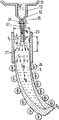
図3に断面を略示した連続鋳造機は、湾曲型連続鋳造機であり、出湯容器11と浸漬ノズル12とを有し、ノズル12は管状部分13と鋤状部分14を有する。17は鋤状部分の長辺面を示す。浸漬ノズル12の部分13、14の移行領域に絞り15が配置されている。鋤状部分14の吐出口は鋳型21内にある溶湯S中に深さTTに至るまで突出している。
【0020】
図示のように、鋳型21の長辺面23の吐出口側にはスラブによって鋳片凝固殻Kが形成され、この鋳片凝固殻Kは湯溜り床エンドSSに至るまで溶湯Sを取り囲んでいる。鋳型21に後続して鋳片案内ロール24が配置されている。
【0021】
供給溶湯SZは速度vKで鋳型21内にある湯溜り床SB中に、短辺面22に関して深さTにまで入り込む。湯溜り床の速度vBはスラブの引抜き速度に、従って鋳片凝固殻Kの引抜き速度に一致する。
上記深さLと深さTとは、図示のように、T<Lの関係にある。
【図面の簡単な説明】
【図1】連続鋳造装置の浸漬ノズルと鋳型領域を示す、鋳型の長辺面に関する縦断面図である。
【図2】図1のA−A線による断面図である。
【図3】湾曲型連続鋳造機の縦断面図であり、鋳型の短辺面に関するものである。
【符号の説明】
11 出湯容器
12 浸漬ノズル
13 管状部分
14 鋤状部分
15 絞り
16 浸漬ノズルの短辺面
17 浸漬ノズルの長辺面
21 鋳型
22 鋳型短辺面
23 鋳型長辺面
24 鋳片案内ロール
I 中心軸線
K 鋳片凝固殻
P 湯面
S 溶湯
SZ 供給溶湯
SB 湯溜り床
SS 湯溜り床エンド
T 短辺面での溶湯浸入深さ
TT 浸漬ノズルの浸漬深さ
L 長辺面での溶湯浸入深さ
vK 供給溶湯の流れ速度
vB 鋳片の引抜き速度(湯溜り床の速度)
α 開き角
a 浸漬ノズル吐出口の自由断面積
b 浸漬ノズルの長辺面の内法幅
d 浸漬ノズルの短辺面の内法幅
A 鋳型の内側断面積
B 鋳型の長辺面の内法幅
D 鋳型の短辺面の内法幅[0001]
The present invention is a method for producing a slab having a casting speed v <3 m / min and a thickness D> 100 mm in a continuous casting machine, wherein molten metal is supplied from a hot water container to a mold via an immersion nozzle. The present invention relates to a method including a step of drawing a slab solidified shell wrapping a floor at a discharge port side into a slab guide roll of a curved continuous casting machine , and an apparatus suitable therefor .
[0002]
According to Steel Research 66 (1995) No. 7, pp. 287-293, “Flow dynamics in thin slab caster moulds”, an experimental apparatus is known in which an immersion nozzle fixed to a tundish protrudes into a mold. The mold used there is about 60 mm in thickness, which is a typical size of a thin slab manufacturing facility, and when using an immersion nozzle having a discharge port (FIG. 10 in the above document), a slab sump A central jet that protrudes deep into the floor is generated.
[0003]
In another configuration (FIG. 4 of the above document), a baffle element is provided at the discharge port of the immersion nozzle, and this baffle element turns the liquid melt to two holes provided on the short side surface of the immersion nozzle. As shown in FIG. 5 of the above-mentioned document, each stream line generates two partial flows, and vortexing of the molten metal having high energy occurs.
[0004]
German patent publication DE 43 20 723 discloses an immersion nozzle, in particular for casting thin slabs, which has a lower part consisting of side walls formed in parallel. A lateral path is provided in front of the entrance to the lower portion, and this lateral path deflects the molten metal flow in the direction of expansion of the lower flow well. The short side surfaces of the immersion nozzle are arranged in parallel to each other .
The known immersion nozzle according to said publication generates a casting flow that enters the sump floor at a relatively high speed to a suitable depth.
[0005]
An object of the present invention is to provide a slab manufacturing method and an apparatus suitable for the same, which can prevent the concentration of impurities and in particular make it possible to cast acid-resistant gas steel or the like even in a curved continuous casting machine.
[0006]
The invention achieves its object by means of the features of the features of method claim 1 and device claim 2 .
[0007]
According to the present invention, the molten liquid supplied to the mold (hereinafter referred to as the supplied molten metal) enters the liquid hot water floor of the slab at a higher speed than the slab drawing speed by widening the front surface. The supplied molten metal has a rectangular cross section and has the same speed as the slab at a depth not exceeding 2 m within the hot water floor.
[0008]
The supply speed v K of the molten metal entering the mold has a relationship of v K : v B = 6: 1 to 60: 1 with respect to the slab drawing speed v B.
[0009]
In one advantageous configuration of the invention, the molten melt is guided into the sump floor from a bowl-shaped part of an immersion nozzle (hereinafter referred to as immersion nozzle) having a rectangular cross section . The internal width d of the short side surface of the immersion nozzle is in a relationship of d: D = 1: 3 to 1:40 with respect to the internal width D of the short side surface of the mold. The width b has a relationship of b: B = 1: 7 to 1: 1.2 with respect to the inner width B of the long side surface of the mold.
[0010]
The streamline S A of the molten metal S exiting the immersion nozzle flows into the hot water bed at a width angle of α = 15 to 30 ° with respect to the slab drawing direction. With respect to the short side of the mold, the feed melt encounters the sump bed S B at a depth of T = 0.1 to 1.5 × D. For this purpose, the short side wall of the immersion nozzle used is open at an angle α of 15 to 30 ° with respect to the central axis (I) . The free sectional area a of the casting port discharge port of the submerged nozzle is in the relationship of a: A = 1: 30 to 1: 300 with respect to the inner sectional area A of the mold. At this time, the internal width d of the short side surface of the immersion nozzle is in a relationship of d: D = 1: 3 to 1:40 with respect to the internal width D of the short side surface of the mold.
[0011]
Sectional produced in a mold by the method of the present invention, further, positive affect its behavior relating to exercise and powder of the melt in the region of the molten metal surface in the mold.
[0012]
Surprisingly, it has been confirmed that when cast according to the present invention, no known concentration differences appear across the slab cross-section and the purity is greatly improved with respect to non-metallic inclusions.
[0013]
And to non-metal purity, also the production of slabs for steel such pairs to harsh conditions are required to continuously segregation as requested, for example, in acid gases steel, made possible by the present invention method.
[0014]
Furthermore, when cast according to the present invention, the rate of full solidification is shortened by reducing the rate of steel inflow into the sump bed in the slab solidified shell, reducing special secondary cooling in terms of improving surface quality. be able to.
[0015]
An
[0016]
The discharge port side of the bowl-
[0017]
Streamline S A supply molten S Z and basin floor S B of the melt S is shown in Figure 1. According to the figure, with respect to the
[0018]
FIG. 2 shows a cross section taken along line AA in FIG. 1. In this figure, the
[0019]
The continuous casting machine whose section is schematically shown in FIG. 3 is a curved continuous casting machine, and has a
[0020]
As shown in the drawing, a slab solidified shell K is formed by a slab on the discharge port side of the
[0021]
The supplied molten metal S Z enters the hot water pool S B in the
The depth L and the depth T are in a relationship of T <L as illustrated.
[Brief description of the drawings]
[1] shows the immersion nozzle and the mold region of a continuous casting apparatus is a vertical sectional view relating to the long side surface of the mold.
FIG. 2 is a cross-sectional view taken along line AA in FIG.
FIG. 3 is a longitudinal sectional view of a curved continuous casting machine and relates to a short side surface of a mold.
[Explanation of symbols]
DESCRIPTION OF
α Opening angle a Free cross-sectional area of submerged nozzle outlet
b Internal width of the long side of the immersion nozzle
d Internal width A of the short side of the immersion nozzle A Inner cross-sectional area of the mold B Internal width of the long side of the mold D Internal width of the short side of the mold
Claims (2)
浸漬ノズル(12)と鋳型(21)の横断面を矩形に形成し、
浸漬ノズル(12)の短辺面(16)の内法幅(d)を鋳型(21)の短辺面(22)の内法幅(D)に対してd:D=1:3〜1:40の関係にし、浸漬ノズル(12)の長辺面(17)の内法幅(b)を鋳型(21)の長辺面(23)の内法幅(B)に対してb:B=1:7〜1:1.2の関係にし、供給溶湯S z が鋳型(21)に入り込む速度(v K )を鋳片引抜き速度(v B )に対してv K :v B =6:1〜60:1の関係にしたものにおいて、
浸漬ノズル(12)を管状部分(13)と鋤状部分(14)とから形成し、鋤状部分(14)の中部と下部には絞り(15)を設けず、浸漬ノズルの管状部分(13)から鋤状部分(14)への移行領域に絞り(15)を設けて鋤状部分(14)に流入する溶湯主流の速度を低減し流れ形状を変え、
浸漬ノズル(12)の鋤状部分(14)の短辺面(16)は中心軸線(I)を基準に15〜30°の角度(α)に開いて形成し、供給溶湯の流線(SA)が鋳型(21)の短辺面(22)向きに、スラブ引抜き方向に対して15〜30°の角度(α)で湯溜り床(SB)中に流れ込み、その一部が湯面Pの領域内で鋳型の中心に向うようにし、浸漬ノズル(12)を介して供給される溶湯Szが、鋳型(21)の短辺面(22)に関して、湯面Pを基準にしてT=0.1〜1.5×Dの深さ(T)で湯溜り床(SB)に遭遇するようにし、
供給溶湯(SZ)は、その流線(SA)が、横断面で矩形断面をなして、鋳型(21)の長辺面(23)に関して、湯面Pを基準にして2mを越えない深さ(L)で湯溜り床(S B )中に入り込み、スラブの速度と同じ速度となるように案内し、
上記(T)と(L)はT<Lの関係にあるようにしたことを特徴とするスラブを製造する方法。A method for producing a slab having a casting speed v <3 m / min and a thickness D> 100 mm by a continuous casting machine, from a hot water container (11) of the continuous casting machine to a mold (21) through an immersion nozzle (12). supplying molten metal, a mold (21) of the billet solidified shell encasing tundish floor (S B) (K) formed at the discharge port side, which slab guide roll bending type continuous casting machine (24) includes the step of pulling out to,
Forming a rectangular cross section of the immersion nozzle (12) and the mold (21);
The internal width (d) of the short side surface (16) of the immersion nozzle (12) is set to d: D = 1: 3 to 1 with respect to the internal width (D) of the short side surface (22) of the mold (21). The internal width (b) of the long side surface (17) of the immersion nozzle (12) is set to b: B with respect to the internal width (B) of the long side surface (23) of the mold (21). = 1: 7 to 1: 1.2, and the speed (v K ) at which the supplied molten metal S z enters the mold (21) is set to v K : v B = 6 with respect to the slab drawing speed (v B ). In the 1-60: 1 relationship,
The submerged nozzle (12) is formed of a tubular part (13) and a bowl-shaped part (14), and the throttle part (15) is not provided in the middle and lower part of the bowl-shaped part (14). ) To a bowl-like part (14), a restriction (15) is provided to reduce the speed of the main melt flowing into the bowl-like part (14) and change the flow shape,
The short side surface (16) of the bowl-shaped portion (14) of the immersion nozzle (12) is formed to open at an angle (α) of 15 to 30 ° with respect to the central axis (I), and the stream line (S A ) flows into the hot water bed (S B ) in the direction of the short side surface (22) of the mold (21) at an angle (α) of 15 to 30 ° with respect to the slab pulling direction, and a part of the hot water surface. In the region of P, the molten metal S z supplied through the immersion nozzle (12) is directed to the center of the mold with respect to the short side surface (22) of the mold (21). = To encounter a hot water floor (S B ) at a depth (T) of 0.1 to 1.5 × D,
The flow line (S A ) of the supply molten metal (S Z ) has a rectangular cross section in cross section, and does not exceed 2 m with respect to the molten metal surface P with respect to the long side surface (23) of the mold (21). enter into the depth (L) in tundish floor (S B), guided so as to have the same speed as the slab speed,
A method for producing a slab, wherein (T) and (L) have a relationship of T <L .
出湯容器(11)に浸漬ノズル(12)を連結し、浸漬ノズル(12)が管状部分(13)と鋤状部分(14)を備え、鋤状部分(14)の下部を鋳型(21)内に設置し、
浸漬ノズル(12)の鋤状部分(14)と鋳型(21)の横断面を矩形に形成し、
鋳型(21)の短辺面の内法幅(D)をD>100mmとし、
浸漬ノズル(12)の短辺面(16)の内法幅(d)を鋳型(21)の短辺面(22)の内法幅(D)に対してd:D=1:3〜1:40になるように形成し、浸漬ノズル(12)の長辺面(17)の内法幅(b)を鋳型(21)の長辺面(23)の内法幅(B)に対してb:B=1:7〜1:1.2になるように形成し、
浸漬ノズル(12)の鋳込部吐出口の自由断面積(a)が鋳型(21)の内側断面積(A)に対してa:A=1:30〜1:300になるように形成したものにおいて、
浸漬ノズル(12)の鋤状部分(14)の中部と下部には絞り(15)を設けず、浸漬ノズルの管状部分(13)から鋤状部分(14)への移行領域に絞り(15)を設け、浸漬ノズル(12)を介して鋳型(21)内に溶湯を案内し、絞り(15)が鋤状部分(14)に流入する溶湯主流の速度を低減し流れ形状を変えるようにし、
矩形横断面を有する鋤状部分(14)を、その短辺面(16)が中心軸線(I)に対して流れ方向に開き角(α)=15〜30°を有するように構成したことを特徴とする連続鋳造装置。 A continuous casting apparatus for producing a slab by the method of claim 1 , comprising:
An immersion nozzle (12) is connected to the hot water container (11), and the immersion nozzle (12) includes a tubular portion (13) and a bowl-shaped portion (14), and the lower portion of the bowl-shaped portion (14) is placed in the mold (21). Installed in
Forming a rectangular cross section of the bowl-shaped portion (14) of the immersion nozzle (12) and the mold (21);
The internal width (D) of the short side surface of the mold (21) is D> 100 mm,
The internal width (d) of the short side surface (16) of the immersion nozzle (12) is set to d: D = 1: 3 to 1 with respect to the internal width (D) of the short side surface (22) of the mold (21). : The inner width (b) of the long side surface (17) of the immersion nozzle (12) is set to be equal to the inner width (B) of the long side surface (23) of the mold (21). b: B = 1: 7 to 1: 1.2
The free cross-sectional area (a) of the casting part discharge port of the immersion nozzle (12) was formed so as to be a: A = 1: 30 to 1: 300 with respect to the inner cross-sectional area (A) of the mold (21). In things,
The diaphragm (15) is not provided in the middle and lower part of the bowl-shaped part (14) of the immersion nozzle (12), and the diaphragm (15) is formed in the transition region from the tubular part (13) of the immersion nozzle to the bowl-shaped part (14). The molten metal is guided into the mold (21) through the immersion nozzle (12), the throttle (15) reduces the speed of the molten main flow flowing into the bowl-shaped part (14), and changes the flow shape.
The saddle-shaped portion (14) having a rectangular cross section is configured such that its short side surface (16) has an opening angle (α) = 15 to 30 ° in the flow direction with respect to the central axis (I). A continuous casting machine.
Applications Claiming Priority (3)
| Application Number | Priority Date | Filing Date | Title |
|---|---|---|---|
| DE19724232A DE19724232C2 (en) | 1997-06-03 | 1997-06-03 | Method and device for producing slabs |
| DE19724232.4 | 1997-06-03 | ||
| PCT/DE1998/001544 WO1998055250A1 (en) | 1997-06-03 | 1998-06-03 | Method and device for producing slabs |
Publications (2)
| Publication Number | Publication Date |
|---|---|
| JP2002501438A JP2002501438A (en) | 2002-01-15 |
| JP4542631B2 true JP4542631B2 (en) | 2010-09-15 |
Family
ID=7831904
Family Applications (1)
| Application Number | Title | Priority Date | Filing Date |
|---|---|---|---|
| JP50130999A Expired - Fee Related JP4542631B2 (en) | 1997-06-03 | 1998-06-03 | Method and apparatus for manufacturing slabs |
Country Status (19)
| Country | Link |
|---|---|
| US (1) | US6626229B2 (en) |
| EP (1) | EP0996513B1 (en) |
| JP (1) | JP4542631B2 (en) |
| KR (1) | KR100585413B1 (en) |
| AT (1) | ATE206971T1 (en) |
| AU (1) | AU8433298A (en) |
| BR (1) | BR9810422A (en) |
| CA (1) | CA2292473A1 (en) |
| CZ (1) | CZ9904328A3 (en) |
| DE (2) | DE19724232C2 (en) |
| DK (1) | DK0996513T3 (en) |
| ES (1) | ES2162461T3 (en) |
| HU (1) | HU221712B1 (en) |
| PL (1) | PL337129A1 (en) |
| SK (1) | SK166399A3 (en) |
| TR (1) | TR199903016T2 (en) |
| TW (1) | TW404867B (en) |
| UA (1) | UA51790C2 (en) |
| WO (1) | WO1998055250A1 (en) |
Families Citing this family (5)
| Publication number | Priority date | Publication date | Assignee | Title |
|---|---|---|---|---|
| AT408962B (en) * | 2000-05-31 | 2002-04-25 | Voest Alpine Ind Anlagen | METHOD FOR PRODUCING A CONTINUOUS PRE-PRODUCT |
| AT507590A1 (en) † | 2008-11-20 | 2010-06-15 | Siemens Vai Metals Tech Gmbh | METHOD AND CONTINUOUS CASTING SYSTEM FOR MANUFACTURING THICK BRAMMS |
| SI2100676T1 (en) * | 2008-12-17 | 2012-10-30 | Peter Kovac | Continuous cast method |
| EP3154726B1 (en) * | 2014-06-11 | 2018-08-15 | Arvedi Steel Engineering S.p.A. | Thin slab nozzle for distributing high mass flow rates |
| CN110695349B (en) * | 2019-11-21 | 2024-03-12 | 辽宁科技大学 | CSP sheet billet continuous casting high-pulling-speed submerged nozzle and manufacturing method thereof |
Family Cites Families (12)
| Publication number | Priority date | Publication date | Assignee | Title |
|---|---|---|---|---|
| DE2105881B2 (en) * | 1971-02-01 | 1974-04-04 | Mannesmann Ag, 4000 Duesseldorf | Device and method for introducing a melt into a continuous casting mold |
| AT331437B (en) * | 1973-06-14 | 1976-08-25 | Voest Ag | CONTINUOUS STEEL CASTING PROCESS AND DEVICE FOR ITS IMPLEMENTATION |
| US5205343A (en) * | 1989-06-03 | 1993-04-27 | Sms Schloemann-Siemag Aktiengesellschaft | Pouring tube for feeding molten steel into a continuous casting mold |
| DE4142447C3 (en) * | 1991-06-21 | 1999-09-09 | Mannesmann Ag | Immersion nozzle - thin slab |
| DE4320723A1 (en) * | 1993-06-23 | 1995-01-05 | Didier Werke Ag | Immersion spout |
| US5785880A (en) * | 1994-03-31 | 1998-07-28 | Vesuvius Usa | Submerged entry nozzle |
| IT1267284B1 (en) * | 1994-08-08 | 1997-01-28 | Danieli Off Mecc | CONTINUOUS CASTING UNLOADER |
| IT1267299B1 (en) * | 1994-09-30 | 1997-01-28 | Danieli Off Mecc | UNLOADER FOR CRYSTALLIZER FOR CONTINUOUS CASTING OF THIN Slabs |
| DE19512208C1 (en) * | 1995-03-21 | 1996-07-18 | Mannesmann Ag | Immersed spout for pouring metal |
| EP0798061A4 (en) * | 1995-10-18 | 1999-06-30 | Sumitomo Metal Ind | Method for controlling the level of molten metal for a continuous casting machine |
| DE19623787C2 (en) * | 1996-06-04 | 1998-07-02 | Mannesmann Ag | Method and device for pouring steel from a dip spout |
| IT1284035B1 (en) * | 1996-06-19 | 1998-05-08 | Giovanni Arvedi | DIVER FOR CONTINUOUS CASTING OF THIN SLABS |
-
1997
- 1997-06-03 DE DE19724232A patent/DE19724232C2/en not_active Expired - Fee Related
-
1998
- 1998-03-06 UA UA99126567A patent/UA51790C2/en unknown
- 1998-06-03 DE DE59801802T patent/DE59801802D1/en not_active Expired - Lifetime
- 1998-06-03 BR BR9810422-5A patent/BR9810422A/en active Search and Examination
- 1998-06-03 WO PCT/DE1998/001544 patent/WO1998055250A1/en active IP Right Grant
- 1998-06-03 AU AU84332/98A patent/AU8433298A/en not_active Abandoned
- 1998-06-03 HU HU0004067A patent/HU221712B1/en not_active IP Right Cessation
- 1998-06-03 JP JP50130999A patent/JP4542631B2/en not_active Expired - Fee Related
- 1998-06-03 ES ES98934867T patent/ES2162461T3/en not_active Expired - Lifetime
- 1998-06-03 TR TR1999/03016T patent/TR199903016T2/en unknown
- 1998-06-03 CZ CZ19994328A patent/CZ9904328A3/en unknown
- 1998-06-03 EP EP98934867A patent/EP0996513B1/en not_active Expired - Lifetime
- 1998-06-03 DK DK98934867T patent/DK0996513T3/en active
- 1998-06-03 CA CA002292473A patent/CA2292473A1/en not_active Abandoned
- 1998-06-03 US US09/445,262 patent/US6626229B2/en not_active Expired - Fee Related
- 1998-06-03 PL PL98337129A patent/PL337129A1/en not_active IP Right Cessation
- 1998-06-03 AT AT98934867T patent/ATE206971T1/en active
- 1998-06-03 KR KR1019997011238A patent/KR100585413B1/en not_active IP Right Cessation
- 1998-06-03 SK SK1663-99A patent/SK166399A3/en unknown
- 1998-10-20 TW TW087117456A patent/TW404867B/en not_active IP Right Cessation
Also Published As
| Publication number | Publication date |
|---|---|
| EP0996513A1 (en) | 2000-05-03 |
| TR199903016T2 (en) | 2000-07-21 |
| HU221712B1 (en) | 2002-12-28 |
| WO1998055250A1 (en) | 1998-12-10 |
| UA51790C2 (en) | 2002-12-16 |
| CZ9904328A3 (en) | 2002-03-13 |
| TW404867B (en) | 2000-09-11 |
| DE19724232A1 (en) | 1998-12-24 |
| US20030150588A1 (en) | 2003-08-14 |
| CA2292473A1 (en) | 1998-12-10 |
| US6626229B2 (en) | 2003-09-30 |
| DE19724232C2 (en) | 1999-04-15 |
| KR20010013247A (en) | 2001-02-26 |
| EP0996513B1 (en) | 2001-10-17 |
| AU8433298A (en) | 1998-12-21 |
| PL337129A1 (en) | 2000-07-31 |
| DK0996513T3 (en) | 2001-11-19 |
| HUP0004067A3 (en) | 2001-05-28 |
| SK166399A3 (en) | 2000-07-11 |
| KR100585413B1 (en) | 2006-06-02 |
| HUP0004067A1 (en) | 2001-03-28 |
| ES2162461T3 (en) | 2001-12-16 |
| ATE206971T1 (en) | 2001-11-15 |
| DE59801802D1 (en) | 2001-11-22 |
| JP2002501438A (en) | 2002-01-15 |
| BR9810422A (en) | 2000-07-25 |
Similar Documents
| Publication | Publication Date | Title |
|---|---|---|
| KR930002836B1 (en) | Method and apparatus for continuous casting | |
| US3648761A (en) | Apparatus for distributing molten steel in a mold for a continuous casting | |
| JP4542631B2 (en) | Method and apparatus for manufacturing slabs | |
| EP2092998B1 (en) | Molten metal continuous casting method | |
| KR101320353B1 (en) | Device for generating ultrasonic wave of submerged type | |
| US6557623B2 (en) | Production method for continuous casting cast billet | |
| US4186791A (en) | Process and apparatus for horizontal continuous casting of metal | |
| KR20130099331A (en) | Collrctor nozzle for ladle | |
| JPH09108793A (en) | Continuous casting method and straight immersion nozzle | |
| RU2741876C1 (en) | Method for continuous casting of slab bills | |
| US6336575B1 (en) | Submerged nozzle for slab continuous casting moulds | |
| CN102292176B (en) | Submerged entry nozzle | |
| CN212264472U (en) | Graphite pouring pipe for vertical continuous casting | |
| JP3399627B2 (en) | Flow control method of molten steel in mold by DC magnetic field | |
| JPH04178247A (en) | Continuous casting method of steel by casting mold having electromagnetic field | |
| RU2148469C1 (en) | Metal continuous casting plant | |
| JPH04238658A (en) | Immersion nozzle for continuous casting | |
| JPH08187557A (en) | Method for continuously casting steel using electromagnetic field | |
| KR20140002931A (en) | Device for adjusting position of stopper | |
| RU2066591C1 (en) | Apparatus for line vacuum treatment of metal under continuous casting | |
| KR101377484B1 (en) | Method for estimating carbon-increasing of molten steel | |
| JP4298128B2 (en) | Stoke structure for differential pressure casting equipment | |
| CN110666148A (en) | FTSC thin slab continuous casting high flux immersion nozzle | |
| KR960015798B1 (en) | Molding apparatus for horizontal continuous casting of hollow billet | |
| KR20140056712A (en) | Method for predicting surface velocity of molten steel in mold |
Legal Events
| Date | Code | Title | Description |
|---|---|---|---|
| A621 | Written request for application examination |
Free format text: JAPANESE INTERMEDIATE CODE: A621 Effective date: 20050526 |
|
| A131 | Notification of reasons for refusal |
Free format text: JAPANESE INTERMEDIATE CODE: A131 Effective date: 20070116 |
|
| A601 | Written request for extension of time |
Free format text: JAPANESE INTERMEDIATE CODE: A601 Effective date: 20070323 |
|
| A602 | Written permission of extension of time |
Free format text: JAPANESE INTERMEDIATE CODE: A602 Effective date: 20070514 |
|
| A521 | Request for written amendment filed |
Free format text: JAPANESE INTERMEDIATE CODE: A523 Effective date: 20070717 |
|
| A02 | Decision of refusal |
Free format text: JAPANESE INTERMEDIATE CODE: A02 Effective date: 20070918 |
|
| A521 | Request for written amendment filed |
Free format text: JAPANESE INTERMEDIATE CODE: A523 Effective date: 20080111 |
|
| A911 | Transfer to examiner for re-examination before appeal (zenchi) |
Free format text: JAPANESE INTERMEDIATE CODE: A911 Effective date: 20080612 |
|
| A912 | Re-examination (zenchi) completed and case transferred to appeal board |
Free format text: JAPANESE INTERMEDIATE CODE: A912 Effective date: 20080703 |
|
| A601 | Written request for extension of time |
Free format text: JAPANESE INTERMEDIATE CODE: A601 Effective date: 20090917 |
|
| A602 | Written permission of extension of time |
Free format text: JAPANESE INTERMEDIATE CODE: A602 Effective date: 20090930 |
|
| A601 | Written request for extension of time |
Free format text: JAPANESE INTERMEDIATE CODE: A601 Effective date: 20100303 |
|
| A602 | Written permission of extension of time |
Free format text: JAPANESE INTERMEDIATE CODE: A602 Effective date: 20100316 |
|
| A521 | Request for written amendment filed |
Free format text: JAPANESE INTERMEDIATE CODE: A523 Effective date: 20100428 |
|
| A01 | Written decision to grant a patent or to grant a registration (utility model) |
Free format text: JAPANESE INTERMEDIATE CODE: A01 |
|
| A61 | First payment of annual fees (during grant procedure) |
Free format text: JAPANESE INTERMEDIATE CODE: A61 Effective date: 20100628 |
|
| R150 | Certificate of patent or registration of utility model |
Free format text: JAPANESE INTERMEDIATE CODE: R150 |
|
| FPAY | Renewal fee payment (event date is renewal date of database) |
Free format text: PAYMENT UNTIL: 20130702 Year of fee payment: 3 |
|
| R250 | Receipt of annual fees |
Free format text: JAPANESE INTERMEDIATE CODE: R250 |
|
| LAPS | Cancellation because of no payment of annual fees |