JP4540387B2 - Zoom lens and imaging device - Google Patents
Zoom lens and imaging device Download PDFInfo
- Publication number
- JP4540387B2 JP4540387B2 JP2004136908A JP2004136908A JP4540387B2 JP 4540387 B2 JP4540387 B2 JP 4540387B2 JP 2004136908 A JP2004136908 A JP 2004136908A JP 2004136908 A JP2004136908 A JP 2004136908A JP 4540387 B2 JP4540387 B2 JP 4540387B2
- Authority
- JP
- Japan
- Prior art keywords
- lens
- lens group
- positive
- zoom
- group
- Prior art date
- Legal status (The legal status is an assumption and is not a legal conclusion. Google has not performed a legal analysis and makes no representation as to the accuracy of the status listed.)
- Expired - Fee Related
Links
Images

Landscapes
- Lenses (AREA)
Description
本発明は、ズームレンズおよび撮像装置に関する。例えば、デジタルカメラやビデオカメラ等の電子撮像装置に適したズームレンズに関する。 The present invention relates to a zoom lens and an imaging apparatus. For example, the present invention relates to a zoom lens suitable for an electronic imaging device such as a digital camera or a video camera.
近年、銀塩35mmフィルムカメラに代わる次世代カメラとしてデジタルカメラが注目されている。さらにそれは業務用高機能タイプからポータブルな普及タイプまで幅広い範囲でいくつものカテゴリーを有するようになっている。特にポータブルな普及タイプのカテゴリーではF値が2.8程度と明るくズーム比が3倍程度と大きく、画角が60°程度と広画角で高画質を確保しながら奥行きの薄いカメラが望まれている。
カメラの奥行き方向を薄くするにあたって最大の課題となるのは、光学系、特にズームレンズ系の最も物体側の面から撮像面までの厚みである。最近では、撮影時に光学系をカメラボディ内からせり出し携帯時に光学系をカメラボディ内に収納するいわゆる沈胴式鏡筒を採用することが主流になっている。
薄型化小型化を実施するには、撮像素子を小さくすればよいが、同じ画素数とするためには画素ピッチを小さくする必要があり、感度不足を光学系でカバーしなければならない。また回折の影響もある。したがってF値の明るい光学系が必要となる。
また、奥行きの薄いカメラボディにするためには、合焦時のレンズ移動を前群繰り出し方式ではなく、いわゆるリアフォーカス方式で行なうことが駆動系のレイアウト上有効である。そのため、リアフォーカス方式を実施した時の収差変動が少ない光学系を選択する必要がある。
例えば、特許文献1、2には、F値が明るくズーム比が3倍程度と大きく画角が広い、比較的コンパクトな負先行の3群構成のズームレンズが開示されている。
また、特許文献2、3には、リアフォーカス方式に適したズームレンズが開示されている。
The greatest problem in reducing the depth direction of the camera is the thickness from the most object side surface to the imaging surface of the optical system, particularly the zoom lens system. Recently, it has become the mainstream to adopt a so-called collapsible lens barrel that protrudes the optical system from the camera body during shooting and stores the optical system in the camera body when carried.
In order to reduce the thickness and size of the image sensor, it is only necessary to reduce the size of the image sensor. However, in order to obtain the same number of pixels, it is necessary to reduce the pixel pitch, and the lack of sensitivity must be covered by the optical system. There is also the effect of diffraction. Therefore, an optical system with a bright F value is required.
In order to obtain a camera body with a small depth, it is effective in terms of the drive system layout to move the lens at the time of focusing by the so-called rear focus method instead of the front group extension method. For this reason, it is necessary to select an optical system with less aberration fluctuation when the rear focus method is performed.
For example,
Patent Documents 2 and 3 disclose zoom lenses suitable for the rear focus method.
しかしながら、上記のような従来のズームレンズには、以下のような問題があった。
特許文献1、2に記載の技術では、第1レンズ群、第2レンズ群で軸外諸収差を除去しきれておらず、残存する収差を第3レンズ群に非球面量の大きなレンズを配置することで除去する構成になっている。そのため第3レンズ群を移動させたときに収差変動が大きくなってしまい、無限遠物点から近距離物点まで安定した良好な結像性能を得ることが難しいという問題がある。そのため、リアフォーカス方式には適さない。
また、特許文献2、3に記載の技術では、広角端または望遠端での最短のレンズ全長が大きく、また変倍時の第2レンズ群移動量が大きいために、第2レンズ群を駆動するカム機構を有する鏡筒部が長くなる。そのため、沈胴時においてもレンズ全長が大きくなってしまうことが考えられ、充分にコンパクトとは言えないという問題がある。
However, the conventional zoom lens as described above has the following problems.
In the techniques described in
In the techniques described in Patent Documents 2 and 3, the shortest lens total length at the wide-angle end or the telephoto end is large, and the second lens group movement amount during zooming is large, so the second lens group is driven. The lens barrel portion having the cam mechanism becomes longer. For this reason, it is conceivable that the total length of the lens becomes large even when the lens barrel is retracted, and there is a problem that it cannot be said to be sufficiently compact.
本発明は、上記のような課題に鑑みてなされたものであって、構成レンズ枚数が少なくコンパクトで、機構レイアウト上、小型で簡素にしやすいリアフォーカス方式に適し、無限遠から近距離まで安定した結像性能を得られるズームレンズを提供することを目的とする。 The present invention has been made in view of the above-described problems, and is compact with a small number of constituent lenses, suitable for a rear focus system that is small and simple in terms of mechanism layout, and has stable connection from infinity to a short distance. An object of the present invention is to provide a zoom lens capable of obtaining image performance.
上記の課題を解決するために、本発明のズームレンズは、物体側より順に、負の屈折力を有する第1レンズ群と、正の屈折力を有する第2レンズ群と、正の屈折力を有する第3レンズ群とからなり、前記第1レンズ群が、物体側より順に、負の第1レンズ、正の第2レンズから構成され、少なくとも1面の非球面を有し、前記第2レンズ群が、物体側より順に、正の第1レンズ、正の第2レンズ、負の第3レンズを備え、前記正の第2レンズおよび前記負の第3レンズが互いに接合されて、物体側に凸面を向けたメニスカス形状の接合レンズをなす構成とされ、該接合レンズの接合面を除く少なくとも2面に非球面を有し、前記第3レンズ群が、球面のみからなる正の単レンズから構成され、無限遠物点合焦時に広角端から望遠端へ変倍する際、前記第1レンズ群が像側に凸の軌跡で移動し、前記第2レンズ群が物体側へのみ移動し、前記第3レンズ群が第2レンズ群とは異なる量で移動しかつ合焦のために可動とされ、以下の条件式(1)、(2)を満足する構成とする。
2.3<Lt/f2<3.7 ・・・(1)
1.15<|f1/f2|<2.0 ・・・(2)
ただし、Ltはズームレンズの望遠端での最も物体側のレンズ面から結像面までの距離、f2は前記第2レンズ群の焦点距離、f1は前記第1レンズ群の焦点距離である。
In order to solve the above problems, the zoom lens of the present invention has, in order from the object side, a first lens group having a negative refractive power, a second lens group having a positive refractive power, and a positive refractive power. The first lens group includes, in order from the object side, a negative first lens and a positive second lens, and has at least one aspheric surface, and the second lens. The group includes, in order from the object side, a positive first lens, a positive second lens, and a negative third lens, and the positive second lens and the negative third lens are joined to each other, Constructed as a meniscus cemented lens having a convex surface, at least two surfaces excluding the cemented surface of the cemented lens have aspheric surfaces, and the third lens group is composed of a positive single lens consisting only of a spherical surface And zooms from the wide-angle end to the telephoto end when focusing on an object point at infinity. The first lens group moves along a convex locus toward the image side, the second lens group moves only toward the object side, and the third lens group moves and focuses in a different amount from the second lens group. Therefore, the following conditional expressions (1) and (2) are satisfied.
2.3 <L t / f 2 <3.7 (1)
1.15 <| f 1 / f 2 | <2.0 (2)
Where L t is the distance from the lens surface closest to the object side to the imaging surface at the telephoto end of the zoom lens, f 2 is the focal length of the second lens group, and f 1 is the focal length of the first lens group. is there.
本発明のズームレンズおよび撮像装置によれば、レンズ構成枚数が少なくコンパクトで、機構レイアウト上小型で簡素にしやすいリアフォーカス方式に適し、無限から近距離まで安定した結像性能が得られるズームレンズおよび撮像装置を提供することができるという効果を奏する。 According to the zoom lens and the imaging apparatus of the present invention, the zoom lens and the imaging device having a small number of lenses, suitable for a rear focus method that is compact and easy to simplify due to a mechanism layout, and that can provide stable imaging performance from infinity to a short distance. There exists an effect that an imaging device can be provided.
各実施形態の説明に先立って本発明の作用について実施例をもとに説明を行う。
本発明のズームレンズは、物体側より負の屈折力を有する第1レンズ群、正の屈折力を有する第2レンズ群、正の屈折力を有する第3レンズ群からなる3群構成を採用しているので、テレセントリック性が良くなり、例えばCCD等の撮像素子に効率的に光線を入射させることができる。また、バックフォーカスを長くとることができるため、光学的ローパスフィルタや赤外線カットフィルタといった部材を配置するスペースが確保できるものである。
Prior to the description of each embodiment, the operation of the present invention will be described based on examples.
The zoom lens of the present invention employs a three-group configuration including a first lens group having negative refractive power from the object side, a second lens group having positive refractive power, and a third lens group having positive refractive power. Therefore, telecentricity is improved, and light can be efficiently incident on an image pickup device such as a CCD. Further, since the back focus can be long, a space for arranging members such as an optical low-pass filter and an infrared cut filter can be secured.
そして、広角端から望遠端への変倍時には、第1レンズ群が像側に凸の軌跡で移動し、第2レンズ群は物体側へのみ移動し、第3レンズ群は第2レンズ群とは異なる量で移動するため、射出瞳距離を適切に保ちながら、全長をコンパクトにすることができる。 At the time of zooming from the wide angle end to the telephoto end, the first lens unit moves along a locus convex to the image side, the second lens unit moves only to the object side, and the third lens unit moves to the second lens unit. Since they move by different amounts, the overall length can be made compact while keeping the exit pupil distance appropriate.
また、第3レンズ群は可動とされ、フォーカス用として使用される。このような第3レンズ群によるリアフォーカス方式は、第1レンズ群によるフォーカスに比べて、移動レンズ群が軽量となるため、移動時に駆動モータにかかる負荷が少ない、全長が大きくならない、鏡枠内部に駆動モータを配置できるため鏡枠の径方向が大きくならない、といった特徴を有し、レイアウト上、小型化に有利となる。 The third lens group is movable and is used for focusing. In such a rear focus method using the third lens group, the moving lens group is lighter than the focus using the first lens group, so the load applied to the drive motor during movement is small, the total length is not increased, and the interior of the lens frame is not increased. Since the drive motor can be disposed in the lens frame, the lens frame has a feature that the radial direction of the lens frame does not increase, which is advantageous for downsizing in terms of layout.
第3レンズ群を変倍時に可動としたり、第3レンズ群を用いてフォーカスをしたりする場合、収差変動が問題になる。第3レンズ群に必要以上の量の非球面が入ると、その効果を出すために第1、2レンズ群に残存する非点収差を第3レンズ群にて補正することになる。ここで第3レンズ群がフォーカスなどのために移動すると収差補正のバランスが崩れてしまうので好ましくない。
本発明のズームレンズでは、第3レンズ群のすべてのレンズ面を非球面ではなく球面にて構成しているので、沈胴収納時のレンズ部総厚さを薄くして、なおかつ第3レンズ群にてフォーカスをする場合でも、収差変動を抑制することができる。
When the third lens group is movable at the time of zooming, or when the third lens group is used for focusing, aberration variation becomes a problem. If an excessive amount of aspherical surface enters the third lens group, the astigmatism remaining in the first and second lens groups is corrected by the third lens group in order to obtain the effect. Here, if the third lens group is moved for focusing or the like, the balance of aberration correction is lost, which is not preferable.
In the zoom lens according to the present invention, since all the lens surfaces of the third lens group are configured as spherical surfaces instead of aspherical surfaces, the total thickness of the lens portion when retracted is reduced, and the third lens group Even when focusing, aberration fluctuations can be suppressed.
一方、第3レンズ群のレンズ面を球面で構成すると非点収差等の補正に負荷がかかる。そのため、第1、2レンズ群により、非点収差をズーム全域にわたりほぼ取り切ることが望ましい。非点収差をはじめとする軸外収差変動を抑制するためには、特に第2レンズ群の収差補正能力が重要である。
そのため、本発明のズームレンズでは、第2レンズ群を、物体側より順に、正の第1レンズ、正の第2レンズ、負の第3レンズを備え、正の第2レンズおよび負の第3レンズが互いに接合されて、物体側に凸面を向けたメニスカス形状の接合レンズをなす構成とし、接合レンズの接合面を除く少なくとも2面に非球面を有するものとしている。
このような構成によれば、第3レンズ群で発生する非点収差等を効果的に補正でき、結像性能を向上することができる。特に、少なくとも2面に非球面を設けるので、効果的に収差補正を行うことができる。
この場合、少なくとも2面の非球面は、接合レンズの接合面を除くレンズ面に設けるので、接合レンズの製作が容易となる。
また、少なくとも2面の非球面は第2レンズ群の正の第1レンズの両面に設けることが好ましい。そうすれば、球面収差補正、群内相対偏心感度の緩和、製造コストの点で大きなメリットが得られる。
On the other hand, if the lens surface of the third lens group is formed of a spherical surface, a load is imposed on correction of astigmatism and the like. For this reason, it is desirable that the first and second lens groups substantially eliminate astigmatism over the entire zoom range. In order to suppress off-axis aberration fluctuations including astigmatism, the aberration correction capability of the second lens group is particularly important.
Therefore, in the zoom lens according to the present invention, the second lens group includes, in order from the object side, the positive first lens, the positive second lens, and the negative third lens, and the positive second lens and the negative third lens. The lenses are cemented together to form a meniscus cemented lens with a convex surface facing the object side, and at least two surfaces excluding the cemented surface of the cemented lens have aspheric surfaces.
According to such a configuration, it is possible to effectively correct astigmatism generated in the third lens group, and to improve the imaging performance. In particular, since aspheric surfaces are provided on at least two surfaces, aberration correction can be performed effectively.
In this case, since at least two aspheric surfaces are provided on the lens surface excluding the cemented surface of the cemented lens, the fabrication of the cemented lens is facilitated.
Further, it is preferable that at least two aspheric surfaces are provided on both surfaces of the positive first lens in the second lens group. In this way, great advantages can be obtained in terms of spherical aberration correction, relaxation of relative decentration sensitivity within the group, and manufacturing costs.
また、このような構成によれば、第2レンズ群内の負の第3レンズが、正の第2レンズで発生する球面収差、コマ収差をキャンセルすることにより、第2レンズ群内で発生する収差量を最小に抑えることができる。また、負の第3レンズを主として球面収差、コマ収差をキャンセルする役目を担うレンズ面を有する正の第2レンズと接合することで相対偏心による収差の発生を抑制できる。
この場合、接合レンズ内で収差をキャンセルするようにして、偏心感度を小さくすることが好ましい。このようにすれば、第2レンズ群の正の第1レンズとの相対偏心感度を小さくすることができる。
このようなレンズ構成では、少なくとも2面の非球面により十分な結像性能が得られる場合、第2レンズ群を、正の第1レンズ、物体側に凸面を向けたメニスカス形状の接合レンズをなす正の第2レンズ、負の第3レンズのみの構成としてもよい。この場合、レンズ枚数の少ない安価な構成とすることができる。
Further, according to such a configuration, the negative third lens in the second lens group is generated in the second lens group by canceling the spherical aberration and coma aberration generated in the positive second lens. The amount of aberration can be minimized. Further, by joining the negative third lens to a positive second lens having a lens surface that mainly serves to cancel spherical aberration and coma aberration, the occurrence of aberration due to relative decentration can be suppressed.
In this case, it is preferable to reduce the decentration sensitivity by canceling the aberration in the cemented lens. In this way, it is possible to reduce the relative decentering sensitivity of the second lens group with the positive first lens.
In such a lens configuration, when sufficient imaging performance is obtained by at least two aspheric surfaces, the second lens group is a positive first lens and a meniscus cemented lens with a convex surface facing the object side. Only a positive second lens and a negative third lens may be used. In this case, an inexpensive configuration with a small number of lenses can be obtained.
また、本発明のズームレンズは、上記の条件式(1)を満足する。条件式(1)は、Lt/f2の範囲によりコンパクト化するのに好適な条件を規定している。
Lt/f2が、条件式(1)の上限を超えると全長が長くなりすぎ、コンパクト化するのが難しくなる。また、Lt/f2が下限を超えて小さくなると、第2レンズ群のパワーが弱くなり、第2レンズ群の変倍作用が小さくなって変倍時の移動量が大きくなる。そのため、コンパクト化が難しくなる。
The zoom lens according to the present invention satisfies the conditional expression (1). Conditional expression (1) prescribes a condition that is suitable for downsizing in the range of L t / f 2 .
If L t / f 2 exceeds the upper limit of conditional expression (1), the total length becomes too long and it becomes difficult to make it compact. Further, when L t / f 2 becomes smaller than the lower limit, the power of the second lens group becomes weak, the zooming action of the second lens group becomes small, and the movement amount during zooming becomes large. For this reason, it is difficult to reduce the size.
ここで、条件式(1)の下限値は、2.5であれば望ましく、2.7であればより望ましい。また、上限値は、3.5であれば望ましく、3.3であればより望ましい。
例えば、以下の条件式(1a)であれば望ましく、条件式(1b)であればより望ましい。
2.5<Lt/f2<3.5 ・・・(1a)
2.7<Lt/f2<3.3 ・・・(1b)
Here, the lower limit value of conditional expression (1) is preferably 2.5, and more preferably 2.7. The upper limit is preferably 3.5, and more preferably 3.3.
For example, the following conditional expression (1a) is desirable, and the conditional expression (1b) is more desirable.
2.5 <L t / f 2 <3.5 (1a)
2.7 <L t / f 2 <3.3 (1b)
また、本発明のズームレンズは、条件式(2)を満足する。
|f1/f2|が、条件式(2)の上限を超えると、第2レンズ群のパワーが強くなりすぎるから、テレセントリック性の確保が難しくなり、画面の隅でのかげり(シェーディング)が発生しやすくなる。また、下限を超えると、第2レンズ群のパワーが弱くなりすぎ、第2レンズ群の変倍作用が小さくなってレンズ移動量が増加する。そのため、レンズ系全体が大きくなってしまう。
The zoom lens according to the present invention satisfies the conditional expression (2).
If | f 1 / f 2 | exceeds the upper limit of the conditional expression (2), the power of the second lens group becomes too strong, so that it becomes difficult to ensure telecentricity and shading at the corners of the screen becomes difficult. It tends to occur. If the lower limit is exceeded, the power of the second lens group becomes too weak, the zooming action of the second lens group becomes small, and the lens movement amount increases. Therefore, the entire lens system becomes large.
ここで、条件式(2)の下限値は1.2であれば望ましく、1.25であればより望ましい。また、上限値は1.75であれば望ましく、1.5であればより望ましい。
例えば、以下の条件式(2a)であれば望ましく、条件式(2b)であればより望ましい。
1.2<|f1/f2|<1.75 ・・・(2a)
1.25<|f1/f2|<1.5 ・・・(2b)
Here, the lower limit value of conditional expression (2) is preferably 1.2, and more preferably 1.25. The upper limit is preferably 1.75, more preferably 1.5.
For example, the following conditional expression (2a) is desirable, and conditional expression (2b) is more desirable.
1.2 <| f 1 / f 2 | <1.75 (2a)
1.25 <| f 1 / f 2 | <1.5 (2b)
本発明のズームレンズでは、第2レンズ群の接合レンズの像側に、正の第4レンズを配置する構成とすることが好ましい。
この場合、正の第4レンズを配置すると、第2レンズ群内の正パワーが分散されるので、第2レンズ群内の相対偏心感度をさらに下げることができる。ただし、収差補正上は第2レンズ群の第4レンズは、パワーレス、または負レンズとしてもよい。
In the zoom lens according to the present invention, it is preferable that a positive fourth lens is disposed on the image side of the cemented lens of the second lens group.
In this case, when the positive fourth lens is arranged, the positive power in the second lens group is dispersed, so that the relative eccentricity sensitivity in the second lens group can be further reduced. However, in terms of aberration correction, the fourth lens of the second lens group may be a powerless or negative lens.
また、第2レンズ群に正の第4レンズを設ける場合、像側に凸面を有する単レンズであることがより好ましい。
この場合、像側に凸面を向けることで、第2レンズ群の正の第4レンズが偏心した場合の性能劣化を小さくすることができる。また沈胴時に、第2レンズ群の後に配置されたメカ部材との機械的干渉を回避できるため、薄型化にも有利である。
In addition, when a positive fourth lens is provided in the second lens group, it is more preferable that the lens is a single lens having a convex surface on the image side.
In this case, by directing the convex surface toward the image side, it is possible to reduce performance degradation when the positive fourth lens of the second lens group is decentered. Further, when retracted, mechanical interference with a mechanical member disposed after the second lens group can be avoided, which is advantageous for thinning.
また、第2レンズ群に正の第4レンズを設ける場合、その像側の面が非球面であることがより好ましい。
この場合、収差補正上有効である。特に第1レンズ群で発生する非点収差や歪曲収差を補正するには、絞りより後の主光線高が高くなる面に非球面を配置することが有効である。
上述のように第3レンズ群のレンズ面に非球面を設けることはリアフォーカスを行う上で好ましくないから、第2レンズ群の最も像側の面に非球面を配置することが望ましい。
なお、第2レンズ群の第4レンズは、ガラスレンズでもプラスチックレンズでもよい。また、ガラス球面上に非球面樹脂を形成させた複合非球面レンズとしてもよい。
Further, when a positive fourth lens is provided in the second lens group, it is more preferable that the image-side surface is an aspherical surface.
In this case, it is effective for aberration correction. In particular, in order to correct astigmatism and distortion occurring in the first lens group, it is effective to arrange an aspherical surface on the surface where the principal ray height is higher after the stop.
As described above, it is not preferable to provide an aspheric surface on the lens surface of the third lens group in terms of rear focusing. Therefore, it is desirable to dispose an aspheric surface on the most image side surface of the second lens group.
The fourth lens in the second lens group may be a glass lens or a plastic lens. Moreover, it is good also as a compound aspherical lens which formed the aspherical resin on the glass spherical surface.
また、本発明のズームレンズは、第2レンズ群の接合レンズが、以下の条件式(5)、(6)を満足することが好ましい。
0.3<R23R/R22F<1.0 ・・・(5)
−0.4<f2/R23F<1.4 ・・・(6)
ただし、f2は第2レンズ群の焦点距離、R22Fは第2レンズ群の正の第2レンズの物体側の面の光軸近傍の曲率半径、R23Rは、第2レンズ群の負の第3レンズの最も像側の面の光軸近傍の曲率半径、R23Fは第2レンズ群の接合レンズの接合面の光軸近傍の曲率半径である。
In the zoom lens according to the present invention, it is preferable that the cemented lens of the second lens group satisfies the following conditional expressions (5) and (6).
0.3 <R 23R / R 22F <1.0 (5)
−0.4 <f 2 / R 23F <1.4 (6)
Where f 2 is the focal length of the second lens group, R 22F is the radius of curvature near the optical axis of the object side surface of the positive second lens of the second lens group, and R 23R is the negative radius of the second lens group. A radius of curvature near the optical axis of the surface closest to the image side of the third lens, and R 23F is a radius of curvature near the optical axis of the cemented surface of the cemented lens of the second lens group.
条件式(5)は、R23R/R22Fの値により、第2レンズ群の接合レンズの好ましい形状の範囲を規定している。
R23R/R22Fが、条件式(5)の上限を超えると、群内での球面収差・コマ収差・非点収差の補正が不十分かつ接合による偏心感度の緩和の効果が少なくなる。下限を超えると、群内の球面収差・コマ収差・非点収差の補正には有利で偏心感度の緩和の効果もあるが、第2レンズ群の倍率を上げるため、小型化に支障をきたしやすい。
Conditional expression (5) defines a preferable shape range of the cemented lens of the second lens group based on the value of R 23R / R 22F .
When R 23R / R 22F exceeds the upper limit of the conditional expression (5), correction of spherical aberration, coma aberration, and astigmatism within the group is insufficient, and the effect of reducing the decentration sensitivity by joining is reduced. Exceeding the lower limit is advantageous for correcting spherical aberration, coma and astigmatism within the group, and also has an effect of reducing decentration sensitivity. However, since the magnification of the second lens group is increased, it tends to hinder downsizing. .
ここで、条件式(5)の下限値は0.4であれば望ましく、0.45であればより望ましい。また、上限値は、0.95であれば望ましく、0.9であればより望ましい。
例えば、以下の条件式(5a)であれば望ましく、条件式(5b)であればより望ましい。
0.4<R23R/R22F<0.95 ・・・(5a)
0.45<R23R/R22F<0.9 ・・・(5b)
Here, the lower limit of conditional expression (5) is preferably 0.4, more preferably 0.45. The upper limit is preferably 0.95, and more preferably 0.9.
For example, the following conditional expression (5a) is desirable, and conditional expression (5b) is more desirable.
0.4 <R 23R / R 22F <0.95 (5a)
0.45 <R 23R / R 22F <0.9 (5b)
条件式(6)は、f2/R23Fの値により、第2レンズ群の焦点距離に対する好ましい接合面の形状の範囲を規定している。
f2/R23Fが、条件式(6)の上限を超えると、軸上色収差、倍率色収差が補正不足になりやすい。下限を超えると、接合レンズ中の正の第2レンズの縁肉を確保するために光軸上での厚みが増大し好ましくない。
Conditional expression (6) defines a preferable range of the shape of the cemented surface with respect to the focal length of the second lens group based on the value of f 2 / R 23F .
If f 2 / R 23F exceeds the upper limit of conditional expression (6), the longitudinal chromatic aberration and the lateral chromatic aberration are likely to be undercorrected. Exceeding the lower limit is not preferable because the thickness on the optical axis increases in order to secure the edge of the positive second lens in the cemented lens.
ここで、条件式(6)の下限値は、0.4であれば望ましく、0.5であればより望ましい。また、上限値は、1.2であれば望ましく、1.0であればより望ましい。
例えば、以下の条件式(6a)であれば望ましく、条件式(6b)であればより望ましい。
0.4<f2/R23F<1.2 ・・・(6a)
0.5<f2/R23F<1.0 ・・・(6b)
Here, the lower limit of conditional expression (6) is desirably 0.4, and more desirably 0.5. The upper limit is preferably 1.2, and more preferably 1.0.
For example, the following conditional expression (6a) is desirable, and conditional expression (6b) is more desirable.
0.4 <f 2 / R 23F <1.2 (6a)
0.5 <f 2 / R 23F <1.0 (6b)
また、本発明のズームレンズは、第2レンズ群の負の第3レンズが、以下の条件式(7を満足することが好ましい。
1.0<|f2/f23|<3.0 ・・・(7)
ただし、f2は第2レンズ群の焦点距離、f23は第2レンズ群の負の第3レンズの焦点距離である。
In the zoom lens according to the present invention, it is preferable that the negative third lens in the second lens group satisfies the following conditional expression (7).
1.0 <| f 2 / f 23 | <3.0 (7)
However, f 2 is the focal length, f 23 of the second lens group is the focal length of the negative third lens in the second lens group.
条件式(7)は、|f2/f23|の値により、第2レンズ群の負の第3レンズの焦点距離と第2レンズ群の焦点距離との好ましい比率の範囲を規定している。
|f2/f23|が条件式(7)の上限を超えると、第2レンズ群の主点が物体側に寄るために全長を短くする作用があるものの、非点収差の補正が困難となる。下限を超えると、第2レンズ群の主点が像側寄りとなって第2レンズ群の倍率が高くならないため、第1レンズ群の移動量が大きくなったり大型化しやすくなってしまう。また、使用状態における第2レンズ群の後方にデッドスペースが生じやすく全長が長くなる。その結果、鏡枠の機械構造が複雑になったり巨大化したりする。あるいは沈胴時にレンズ全長を薄くできなくなる。
Conditional expression (7) defines a range of a preferable ratio between the focal length of the negative third lens and the focal length of the second lens group based on the value of | f 2 / f 23 |. .
If | f 2 / f 23 | exceeds the upper limit of the conditional expression (7), the principal point of the second lens group is closer to the object side, so that the total length is shortened, but it is difficult to correct astigmatism. Become. If the lower limit is exceeded, the principal point of the second lens group is closer to the image side, and the magnification of the second lens group does not increase, so the amount of movement of the first lens group tends to be large or large. In addition, a dead space tends to occur behind the second lens group in the use state, and the entire length becomes long. As a result, the mechanical structure of the lens frame becomes complicated or enlarged. Alternatively, the entire length of the lens cannot be reduced when retracted.
ここで、条件式(7)の下限値は、1.3であれば望ましく、1.6であればより望ましい。また、上限値は、2.5であれば望ましく、2.0であればより望ましい。
例えば、以下の条件式(7a)であれば望ましく、条件式(7b)であればより望ましい。
1.3<|f2/f23|<2.5 ・・・(7a)
1.6<|f2/f23|<2.0 ・・・(7b)
Here, the lower limit value of conditional expression (7) is preferably 1.3, and more preferably 1.6. The upper limit is preferably 2.5, and more preferably 2.0.
For example, the following conditional expression (7a) is desirable, and conditional expression (7b) is more desirable.
1.3 <| f 2 / f 23 | <2.5 (7a)
1.6 <| f 2 / f 23 | <2.0 (7b)
また、本発明のズームレンズは、第1レンズ群が、物体側より順に、負の第1レンズ、正の第2レンズから構成され、少なくとも1面の非球面を有する。
このように少なくとも1面の非球面を有する2枚構成とするので、色収差や各軸外収差が良好に補正可能であり、ズームレンズの薄型化に貢献することができる。
In the zoom lens of the present invention, the first lens group includes, in order from the object side, a negative first lens and a positive second lens, and has at least one aspheric surface.
Since the two-lens configuration having at least one aspherical surface can be corrected satisfactorily, chromatic aberration and each off-axis aberration can be corrected well, and the zoom lens can be made thinner.
また、本発明のズームレンズでは、第1レンズ群の負の第1レンズに、d線(波長587.56nm)に対する屈折率が1.75以上の硝材を用いることが好ましい。そうすれば、曲率を大きくすることなく良好な屈折力が得られるので、軸外諸収差の発生を最小に抑えることができる。
また、本発明のズームレンズでは、第1レンズ群の負の第1レンズは、物体側の面に比べより強い曲率を有する凹面を像側に備え、像側の凹面が非球面からなることが好ましい。そうすれば、特に広角端で発生する歪曲収差、像面湾曲を効果的に補正することができる。このレンズはガラス成型による非球面レンズとしてもよいし、ガラス球面上に非球面樹脂を形成させた複合非球面レンズとしてもよい。
In the zoom lens according to the present invention, it is preferable to use a glass material having a refractive index of 1.75 or more for the d-line (wavelength 587.56 nm) for the negative first lens in the first lens group. By doing so, a good refractive power can be obtained without increasing the curvature, so that the occurrence of various off-axis aberrations can be minimized.
In the zoom lens according to the present invention, the negative first lens of the first lens group may include a concave surface having a stronger curvature than the object-side surface on the image side, and the image-side concave surface may be an aspherical surface. preferable. By doing so, it is possible to effectively correct distortion and field curvature that occur particularly at the wide-angle end. This lens may be an aspherical lens formed by glass molding, or a composite aspherical lens in which an aspherical resin is formed on a glass spherical surface.
また、本発明のズームレンズでは、第1レンズ群の正の第2レンズに、d線に対する屈折率が1.85以上の硝材の硝材を用いることが好ましい。負の第1レンズと同様な理由で、軸外諸収差の発生を最小に抑えることができる。この場合、d線に対する屈折率が1.90以上の硝材の硝材を用いることがより好ましい。 In the zoom lens of the present invention, it is preferable to use a glass material having a refractive index with respect to d-line of 1.85 or more for the positive second lens in the first lens group. For the same reason as the negative first lens, it is possible to minimize the occurrence of off-axis aberrations. In this case, it is more preferable to use a glass material having a refractive index with respect to d-line of 1.90 or more.
また、本発明のズームレンズでは、第1レンズ群の正の第2レンズが、次の条件(8)式を満足することが好ましい。
−2.5<(R13+R14)/(R13−R14)<−0.4 ・・・(8)
ただし、R13は第1レンズ群の正の第2レンズの物体側の面の曲率半径、R14は第1レンズ群の正の第2レンズの像側の面の曲率半径である。
In the zoom lens of the present invention, it is preferable that the positive second lens in the first lens group satisfies the following condition (8).
−2.5 <(R 13 + R 14 ) / (R 13 −R 14 ) <− 0.4 (8)
Here, R 13 is the radius of curvature of the object-side surface of the positive second lens of the first lens group, and R 14 is the radius of curvature of the image-side surface of the positive second lens of the first lens group.
条件式(8)は、(R13+R14)/(R13−R14)の値により、第1レンズ群の正の第2レンズの好ましい形状を規定している。
(R13+R14)/(R13−R14)が、条件式(8)の上限を超えると、歪曲収差の補正が不利になりやすい。下限を超えると、非点収差の補正上不利になりやすい。また、変倍時の機械的干渉を避けるために第2レンズ群との間隔が余分に必要となるのでコンパクト化に不利である。
Conditional expression (8) defines a preferable shape of the positive second lens in the first lens group based on the value of (R 13 + R 14 ) / (R 13 −R 14 ).
If (R 13 + R 14 ) / (R 13 −R 14 ) exceeds the upper limit of conditional expression (8), correction of distortion aberration tends to be disadvantageous. Exceeding the lower limit tends to be disadvantageous in correcting astigmatism. In addition, in order to avoid mechanical interference at the time of zooming, an extra space with the second lens group is necessary, which is disadvantageous for downsizing.
ここで、条件式(8)の下限値は、−2.4であれば望ましく、−2.3であればより望ましい。また、上限値は、−0.45であれば望ましく、−0.5であればより望ましい。
例えば、以下の条件式(8a)であれば望ましく、条件式(8b)であればより望ましい。
−2.4<(R13+R14)/(R13−R14)<−0.45・・・(8a)
−2.3<(R13+R14)/(R13−R14)<−0.5 ・・・(8b)
Here, the lower limit of conditional expression (8) is preferably −2.4, more preferably −2.3. Further, the upper limit value is desirably −0.45, and more desirably −0.5.
For example, the following conditional expression (8a) is desirable, and conditional expression (8b) is more desirable.
−2.4 <(R 13 + R 14 ) / (R 13 −R 14 ) <− 0.45 (8a)
−2.3 <(R 13 + R 14 ) / (R 13 −R 14 ) <− 0.5 (8b)
また、本発明のズームレンズでは、第1レンズ群の正の第2レンズが両面に非球面を有することが好ましい。
この場合、物体側の面では、レンズの外周部で正の屈折力が強くなるような非球面形状にすることがより好ましい。このようにすれば、第1レンズ群の負の第1レンズの外径を小さくすることができるとともに、広角端における歪曲収差、非点収差を効果的に補正できる。また、像側の面でも、同様の理由により、レンズの外周部で正の屈折力が強くなるような非球面形状にすることがより好ましい。
In the zoom lens of the present invention, it is preferable that the positive second lens in the first lens group has aspheric surfaces on both sides.
In this case, it is more preferable that the object side surface has an aspherical shape in which positive refractive power is increased at the outer peripheral portion of the lens. In this way, the outer diameter of the negative first lens in the first lens group can be reduced, and distortion and astigmatism at the wide angle end can be effectively corrected. Further, for the same reason, it is more preferable that the surface on the image side has an aspheric shape in which the positive refractive power is increased at the outer peripheral portion of the lens.
また、この場合、非球面形状に関して、以下の条件式(9)を満足することが好ましい。
0.01<(Asp12F−Asp12R)/fW<0.05 ・・・(9)
ただし、Asp12F、Asp12Rは、それぞれ第1レンズ群内の正の第2レンズの物体側、像側の非球面が有する光軸近傍での曲率半径(近軸曲率半径)の球面に対する有効径での非球面偏奇量、fWは広角端でのズームレンズ全系の焦点距離である。
In this case, it is preferable that the following conditional expression (9) is satisfied with respect to the aspherical shape.
0.01 <(A sp12F −A sp12R ) / f W <0.05 (9)
However, A sp12F and A sp12R are effective diameters with respect to the spherical surface of the curvature radius (paraxial curvature radius) in the vicinity of the optical axis of the object-side and image-side aspheric surfaces of the positive second lens in the first lens group, respectively. aspheric biased amount of, f W is the focal length of the zoom lens system in the wide-angle end.
条件式(9)は、(Asp12F−Asp12R)/fWの値により好ましい非球面形状の範囲を規定している。
(Asp12F−Asp12R)/fWが、条件式(9)の上限を超えて非球面量が大きくなると、軸外のコマ収差の補正が困難になる。下限を超えると、負の歪曲収差の補正不足になり、また軸外の像面湾曲、非点較差が補正できない。
Conditional expression (9) defines a preferable range of the aspheric shape by the value of (A sp12F −A sp12R ) / f W.
When (A sp12F −A sp12R ) / f W exceeds the upper limit of the conditional expression (9) and the aspheric amount becomes large, it is difficult to correct off-axis coma. If the lower limit is exceeded, the negative distortion will be insufficiently corrected, and off-axis field curvature and astigmatism cannot be corrected.
ここで、条件式(9)の下限値は0.015であれば望ましく、0,02であればより望ましい。また、上限値は0.04であれば望ましく、0.03であればより望ましい。
例えば、以下の条件式(9a)であれば望ましく、条件式(9b)であればより望ましい。
0.015<(Asp12F−Asp12R)/fW<0.04 ・・・(9a)
0.02<(Asp12F−Asp12R)/fW<0.03 ・・・(9b)
Here, the lower limit value of conditional expression (9) is preferably 0.015, more preferably 0.02. The upper limit is preferably 0.04, more preferably 0.03.
For example, the following conditional expression (9a) is desirable, and conditional expression (9b) is more desirable.
0.015 <(A sp12F −A sp12R ) / f W <0.04 (9a)
0.02 <(A sp12F −A sp12R ) / f W <0.03 (9b)
また、本発明のズームレンズでは、第3レンズ群が、広角端から望遠端に変倍する際に像側に凸の軌跡を動く様にすることが好ましい。
この場合、特に出来栄え誤差によるピント位置のばらつきの大きな望遠端における調整余裕量の確保が容易になる。
In the zoom lens of the present invention, it is preferable that the third lens group moves along a locus convex toward the image side when zooming from the wide-angle end to the telephoto end.
In this case, it becomes easy to secure an adjustment margin especially at the telephoto end where the variation in the focus position due to the quality error is large.
また、本発明のズームレンズでは、第3レンズ群を正レンズ1枚で構成している。
このような構成では、実用的な収差レベルの補正が可能であり、レンズ枚数を低減して、ズームレンズの薄型化に貢献することができる。
In the zoom lens of the present invention, the third lens group is composed of one positive lens.
With such a configuration, a practical aberration level can be corrected, and the number of lenses can be reduced to contribute to a reduction in the thickness of the zoom lens.
また、本発明のズームレンズでは、第3レンズ群が、以下の条件式(3)を満足することが好ましい。
0.29<fW/f3<0.6 ・・・(3)
ただし、fWは広角端でのズームレンズ全系の焦点距離、f3は前記第3レンズ群の焦点距離である。
In the zoom lens according to the present invention, it is preferable that the third lens group satisfies the following conditional expression (3).
0.29 <f W / f 3 <0.6 (3)
Here, f W is the focal length of the entire zoom lens system at the wide angle end, and f 3 is the focal length of the third lens group.
条件式(3)は、fW/f3の値の範囲により、好ましい第3レンズ群の屈折力の範囲を規定している。
fW/f3が、条件式(3)の上限を超えて第3レンズ群の屈折力が強くなると、第3レンズ群で発生するコマ収差、像面湾曲が大きくなり、リアフォーカスをするのが難しくなる。下限を超えて第3レンズ群の屈折力が弱くなると、バックフォーカスが増大したり、フォーカシング時の第3レンズ群の移動量が大きくなったりするので、コンパクト化するのが難しくなる。条件式(3)は、第3レンズ群のレンズ面を球面で構成する場合に特に有用である。
Conditional expression (3) defines a preferable range of the refractive power of the third lens group based on the range of the value of f W / f 3 .
When f W / f 3 exceeds the upper limit of conditional expression (3) and the refractive power of the third lens group becomes strong, coma aberration and field curvature generated in the third lens group increase, and rear focusing is performed. Becomes difficult. When the refractive power of the third lens unit becomes weaker beyond the lower limit, the back focus increases or the amount of movement of the third lens unit during focusing becomes large, which makes it difficult to make the system compact. Conditional expression (3) is particularly useful when the lens surface of the third lens group is a spherical surface.
ここで、条件式(3)の下限値は、0.3であれば望ましく、0.31であればより望ましい。また上限値は、0.5であれば望ましく、0.45であればより望ましい。
例えば、以下の条件式(3a)であれば望ましく、条件式(3b)であればより望ましい。
0.3<fW/f3<0.5 ・・・(3a)
0.31<fW/f3<0.45 ・・・(3b)
Here, the lower limit value of conditional expression (3) is desirably 0.3, and more desirably 0.31. The upper limit is preferably 0.5, and more preferably 0.45.
For example, the following conditional expression (3a) is desirable, and conditional expression (3b) is more desirable.
0.3 <f W / f 3 <0.5 (3a)
0.31 <f W / f 3 <0.45 (3b)
また、本発明のズームレンズでは、開口絞りを配置する位置は、第1レンズ群と第2レンズ群との間に配置することが好ましい。
この場合、入射瞳位置を浅くできるため前玉径が小さくでき、結果として光軸上のレンズ肉厚を薄くできるため、厚さ方向のコンパクト化に貢献することができる。
また射出瞳位置を結像位置から遠くできるので、例えばCCDなどの撮像素子に射出する光線角度を小さくでき、画面の端でのかげり(シェーディング)の発生を防ぐことができる。
また、開口絞りは、変倍時に第2レンズ群と一体して移動することが好ましい、
この場合、機構上単純であるばかりでなく、沈胴時のデッドスペースが発生しにくく、広角端と望遠端のF値の差が小さくなるという利点がある。
In the zoom lens according to the present invention, the position where the aperture stop is disposed is preferably disposed between the first lens group and the second lens group.
In this case, since the entrance pupil position can be made shallow, the diameter of the front lens can be made small, and as a result, the lens thickness on the optical axis can be made thin, which can contribute to downsizing in the thickness direction.
Further, since the exit pupil position can be set far from the imaging position, for example, the angle of the light beam emitted to the image sensor such as a CCD can be reduced, and the occurrence of shading at the edge of the screen can be prevented.
The aperture stop preferably moves integrally with the second lens group at the time of zooming.
In this case, there is an advantage that not only the mechanism is simple but also a dead space at the time of retraction is not easily generated, and the difference in F value between the wide-angle end and the telephoto end is reduced.
本発明の撮像装置は、本発明のズームレンズと、該ズームレンズの結像位置に撮像素子を配置した構成とする。
この発明によれば、本発明のズームレンズを用いて、被写体の像を撮像素子上に結像できるから、本発明のズームレンズと同様の作用効果を備える撮像装置となる。
The image pickup apparatus of the present invention has a configuration in which the zoom lens of the present invention and an image sensor are arranged at the image forming position of the zoom lens.
According to the present invention, an image of a subject can be formed on the image sensor using the zoom lens of the present invention, so that the image pickup apparatus has the same effects as the zoom lens of the present invention.
なお、上記各条件式や各構成は、適宜組み合わせることで、より良好なズームレンズ、電子撮像装置を構成できる。また各条件式においては、その上限値のみ、もしくは下限値のみを、より好ましい条件式の対応する上限値,下限値で限定してもよい。また、後述の各実施例に記載の条件式の対応値を上限値または下限値としてもよい。 It should be noted that a more favorable zoom lens and electronic imaging apparatus can be configured by appropriately combining the above conditional expressions and configurations. In each conditional expression, only the upper limit value or only the lower limit value may be limited by the corresponding upper limit value and lower limit value of the more preferable conditional expression. Moreover, it is good also considering the corresponding value of the conditional expression as described in each below-mentioned Example as an upper limit or a lower limit.
以下では、本発明の実施の形態を、添付図面を参照して説明する。
[第1の実施形態]
本発明の第1の実施形態に係るズームレンズについて説明する。
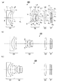
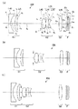
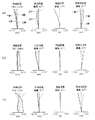
図1(a)、(b)、(c)は、本発明の第1の実施形態に係る第1実施例のズームレンズの無限遠物点合焦時の、それぞれ広角端、中間状態、望遠端でのレンズ断面図である。この図中において、符号Iは像面を示す。なお、これらの詳細な数値実施例は実施例1として後記する。
Hereinafter, embodiments of the present invention will be described with reference to the accompanying drawings.
[First Embodiment]
A zoom lens according to the first embodiment of the present invention will be described.
FIGS. 1A, 1B, and 1C show the wide-angle end, the intermediate state, and the telephoto, respectively, at the time of focusing on an object point at infinity of the zoom lens of the first example according to the first embodiment of the present invention. It is lens sectional drawing at an end. In this figure, the symbol I indicates the image plane. These detailed numerical examples will be described later as Example 1.
本実施形態の第1実施例のズームレンズ100の概略構成は、図1(a)に示すように、第1レンズ群G1、第2レンズ群G2、第3レンズ群G3、平行平板群Fからなり、この順に物体側から配置されている。
As shown in FIG. 1A, the schematic configuration of the
第1レンズ群G1は、物体側より順に、負レンズL1(負の第1レンズ)と、正レンズL2(正の第2レンズ)とからなり、これらにより負の屈折力を有するレンズ群とされる。
負レンズL1は、物体側の面に比べより強い曲率を有する凹面を像側に備え、像側の凹面が非球面からなるレンズで構成される。そして、d線に対する屈折率が1.75以上の硝材からなる。
正レンズL2は、物体側に凸面を向けた正メニスカスレンズで構成される。
なお、以下では誤解の恐れのない限り、負レンズL1、正レンズL2などを総称するとき、正負などを省略して単にレンズL1、L2などと略称する場合がある。
The first lens group G1 is composed of, in order from the object side, a negative lens L1 (negative first lens) and a positive lens L2 (positive second lens), thereby forming a lens group having negative refractive power. The
The negative lens L1 includes a concave surface having a stronger curvature than the object-side surface on the image side, and the image-side concave surface is an aspherical lens. And it consists of a glass material whose refractive index with respect to d line | wire is 1.75 or more.
The positive lens L2 is a positive meniscus lens having a convex surface facing the object side .
In the following description, unless there is a possibility of misunderstanding, the negative lens L1, the positive lens L2, and the like are collectively referred to as the lenses L1, L2, etc., omitting the positive and negative signs.
第2レンズ群G2は、物体側より順に、正レンズL3(正の第1レンズ)と、接合レンズL4と、正レンズL7(正の第4レンズ)とからなり、これらにより正の屈折力を有するレンズ群とされる。第2レンズ群G2の物体側には、変倍時に第2レンズ群G2と一体的に移動する開口絞りSが設けられている。
正レンズL3は、両面に非球面を有する両凸レンズで構成される。
接合レンズL4は、物体側より順に、物体側に凸面を向けた正メニスカスレンズからなる正レンズL5(正の第2レンズ)、物体側に凸面を向けた負メニスカスレンズからなると負レンズL6(負の第3レンズ)により構成される。正レンズL5、負レンズL6は、各レンズ面が球面からなる。
正レンズL7は、像側に凸面を向けた単レンズからなり、像側の凸面に非球面を有する構成とされる。
The second lens group G2, in order from the object side, a positive lens L3 (positive first lens) and a cemented lens L4, it from the positive lens L7 (a fourth positive lens), the positive refractive power these A lens group. An aperture stop S that moves integrally with the second lens group G2 at the time of zooming is provided on the object side of the second lens group G2.
The positive lens L3 is composed of a biconvex lens having aspheric surfaces on both sides.
The cemented lens L4, in order from the object side, is a positive lens L5 (positive second lens) composed of a positive meniscus lens having a convex surface facing the object side, and a negative lens L6 (negative) when composed of a negative meniscus lens having a convex surface directed to the object side. 3rd lens). Each of the positive lens L5 and the negative lens L6 has a spherical surface.
The positive lens L7 includes a single lens having a convex surface facing the image side, and has an aspheric surface on the convex surface on the image side.
第3レンズ群G3は、両面が球面のみの両凸単レンズからなる正レンズL8(正の単レンズ)で構成される。 The third lens group G3 is composed of a positive lens L8 (positive single lens) composed of a biconvex single lens having only spherical surfaces on both sides.
平行平板群Fは、像面Iに配置する撮像素子などの特性により適宜の特性のものをすることができるが、本実施形態では、物体側より順に、光学的ローパスフィルタF1、およびカバーガラスGLから構成され、最終レンズ群と像面Iの間に固定配置されている。
光学的ローパスフィルタF1としては、結晶軸方向が調整された水晶板などからなる複屈折型ローパスフィルタや、回折効果を用いて光学的な遮断周波数特性を実現する位相型ローパスフィルタなどを好適に採用することができる。
また、カバーガラスGLは、CCDなどの撮像素子を配置する場合のカバーガラスである。
また、この他に、例えば平行平板に赤外光を遮断する蒸着を施した赤外光カットフィルタなどを設けてもよい。
なお、これらは場合によっては、一部または全部を割愛してもよい。
The parallel plate group F can have an appropriate characteristic depending on the characteristics of the image sensor or the like arranged on the image plane I. In this embodiment, the optical low-pass filter F1 and the cover glass GL are sequentially arranged from the object side. And fixedly arranged between the last lens group and the image plane I.
As the optical low-pass filter F1, a birefringent low-pass filter made of a crystal plate whose crystal axis direction is adjusted, a phase-type low-pass filter that realizes an optical cutoff frequency characteristic using a diffraction effect, and the like are preferably used. can do.
The cover glass GL is a cover glass when an image pickup device such as a CCD is arranged.
In addition, for example, an infrared light cut filter in which vapor deposition for blocking infrared light is performed on a parallel plate may be provided.
In some cases, some or all of these may be omitted.
ズームレンズ100は、図1(a)、(b)、(c)に示したように、無限遠物点合焦時に広角端から望遠端に変倍する際は、第1レンズ群G1が光軸に沿って像側に凸の軌跡を移動し、第2レンズ群G2が開口絞りSと一体的に光軸に沿って物体側のみに移動し、第3レンズ群G3が光軸に沿って第2レンズ群G2とは異なる量で、像側に凸の軌跡を移動する。そして、第3レンズ群G3は、合焦のため可動とされている。
As shown in FIGS. 1A, 1B, and 1C, when the
次に、本実施形態の第2実施例に係るズームレンズについて説明する。
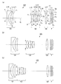
図2(a)、(b)、(c)は、本発明の第1の実施形態に係る第2実施例のズームレンズの無限遠物点合焦時の、それぞれ広角端、中間状態、望遠端でのレンズ断面図である。この図中において、符号Iは像面を示す。なお、これらの詳細な数値実施例は実施例2として後記する。
Next, a zoom lens according to Example 2 of the present embodiment will be described.
FIGS. 2A, 2B, and 2C are respectively a wide angle end, an intermediate state, and a telephoto when the zoom lens of the second example according to the first embodiment of the present invention is focused on an object point at infinity. It is lens sectional drawing at an end. In this figure, the symbol I indicates the image plane. These detailed numerical examples will be described later as Example 2.
第2実施例のズームレンズ101の概略構成は、図2(a)に示すように、上記実施形態の第1実施例のレンズL1〜L8に対応して、屈折力の正負が一致した同タイプのレンズ形状を有するレンズL10〜L17を備える。なお、開口絞りS、平行平板群Fは上記第1実施例と共通である。
As shown in FIG. 2A, the schematic configuration of the
ズームレンズ101は、図2(a)、(b)、(c)に示したように、無限遠物点合焦時に広角端から望遠端に変倍する際は、第1レンズ群G1が光軸に沿って像側に凸の軌跡を移動し、第2レンズ群G2が開口絞りSと一体的に光軸に沿って物体側のみに移動し、第3レンズ群G3が光軸に沿って第2レンズ群G2とは異なる量で像面側に移動する。そして、第3レンズ群G3は、合焦のため可動とされている。
As shown in FIGS. 2A, 2B, and 2C, when the
次に、本実施形態の第3実施例に係るズームレンズについて説明する。
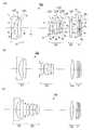
図3(a)、(b)、(c)は、本発明の第1の実施形態に係る第3実施例のズームレンズの無限遠物点合焦時の、それぞれ広角端、中間状態、望遠端でのレンズ断面図である。この図中において、符号Iは像面を示す。なお、これらの詳細な数値実施例は実施例3として後記する。
Next, a zoom lens according to Example 3 of the present embodiment will be described.
FIGS. 3A, 3B, and 3C show the wide-angle end, the intermediate state, and the telephoto, respectively, at the time of focusing on an object point at infinity of the zoom lens of the third example according to the first embodiment of the present invention. It is lens sectional drawing at an end. In this figure, the symbol I indicates the image plane. These detailed numerical examples will be described later as Example 3.
第3実施例のズームレンズ102の概略構成は、図3(a)に示すように、上記実施形態の第1実施例のレンズL1、L3〜6、L8に対応して、屈折力の正負が一致した同タイプのレンズ形状を有するレンズL20、L22〜25、L27を備える。
また、第1実施例の正レンズL2に代えて、正レンズL21(正の第2レンズ)を、同じく正レンズL7に代えて、正レンズ26(正の第4レンズ)を備える。
正レンズL21は、両面に非球面を有することにより正の屈折力を有する単レンズから構成される。そして、d線に対する屈折率が1.85より小さい硝材からなる。
正レンズ26は、像側に凸面を有する単レンズであり、像側の面に非球面を有する構成とされる。
なお、開口絞りS、平行平板群Fは上記第1実施例と共通である。
As shown in FIG. 3A, the schematic configuration of the
Further, provided in place of the positive lens L 2 of the first embodiment, the positive lens L21 (second positive lens), also in place of the positive lens L7, a positive lens 26 (fourth positive lens).
The positive lens L21 is composed of a single lens having positive refractive power by having aspheric surfaces on both sides. And it consists of a glass material whose refractive index with respect to d line is smaller than 1.85.
The positive lens 26 is a single lens having a convex surface on the image side, and has an aspherical surface on the image side surface.
The aperture stop S and the parallel plate group F are the same as those in the first embodiment.
ズームレンズ102は、図3(a)、(b)、(c)に示したように、無限遠物点合焦時に広角端から望遠端に変倍する際は、第1レンズ群G1が光軸に沿って像側に凸の軌跡を移動し、第2レンズ群G2が開口絞りSと一体的に光軸に沿って物体側のみに移動し、第3レンズ群G3が光軸に沿って第2レンズ群G2とは異なる量で移動する。そして、第3レンズ群G3は、合焦のため可動とされている。
As shown in FIGS. 3A, 3B, and 3C, when the
次に、本実施形態の第4実施例に係るズームレンズについて説明する。
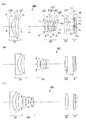
図4(a)、(b)、(c)は、本発明の第1の実施形態に係る第4実施例のズームレンズの無限遠物点合焦時の、それぞれ広角端、中間状態、望遠端でのレンズ断面図である。この図中において、符号Iは像面を示す。なお、これらの詳細な数値実施例は実施例4として後記する。
Next, a zoom lens according to Example 4 of the present embodiment will be described.
FIGS. 4A, 4B, and 4C show the wide-angle end, the intermediate state, and the telephoto, respectively, when the zoom lens of Example 4 according to the first embodiment of the present invention is focused on an object point at infinity. It is lens sectional drawing at an end. In this figure, the symbol I indicates the image plane. These detailed numerical examples will be described later as Example 4.
第4実施例のズームレンズ103の概略構成は、図4(a)に示すように、上記実施形態の第1実施例のレンズL1〜6、L8に対応して、屈折力の正負が一致した同タイプのレンズ形状を有するレンズL30〜35、L37を備える。
また、第1実施例の正レンズL7に代えて、正レンズ36(正の第4レンズ)を備える。
正レンズ36は、像側に凸面を有する単レンズであり、両面に球面を有する構成とされる。
なお、開口絞りS、平行平板群Fは上記第1実施例と共通である。
As shown in FIG. 4A, the schematic configuration of the
Further, a positive lens 36 (positive fourth lens) is provided instead of the positive lens L7 of the first embodiment.
The positive lens 36 is a single lens having a convex surface on the image side, and has a spherical surface on both surfaces.
The aperture stop S and the parallel plate group F are the same as those in the first embodiment.
ズームレンズ103は、図4(a)、(b)、(c)に示したように、無限遠物点合焦時に広角端から望遠端に変倍する際は、第1レンズ群G1が光軸に沿って像側に凸の軌跡を移動し、第2レンズ群G2が開口絞りSと一体的に光軸に沿って物体側のみに移動し、第3レンズ群G3が光軸に沿って第2レンズ群G2とは異なる量で移動する。そして、第3レンズ群G3は、合焦のため可動とされている。
As shown in FIGS. 4A, 4B, and 4C, when the
次に、本実施形態の参考例に係るズームレンズについて説明する。
図5(a)、(b)、(c)は、本発明の第1の実施形態に係る参考例のズームレンズの無限遠物点合焦時の、それぞれ広角端、中間状態、望遠端でのレンズ断面図である。この図中において、符号Iは像面を示す。なお、これらの詳細な数値実施例は参考例として後記する。
Next, a zoom lens according to a reference example of this embodiment will be described.
FIGS. 5A, 5B, and 5C are a wide angle end, an intermediate state, and a telephoto end, respectively, when focusing on an object point at infinity of the zoom lens of the reference example according to the first embodiment of the present invention. FIG. In this figure, the symbol I indicates the image plane. These detailed numerical examples will be described later as reference examples .
参考例のズームレンズ104の概略構成は、図5(a)に示すように、上記実施形態の第1実施例のレンズL1〜3、L8に対応して、屈折力の正負が一致した同タイプのレンズ形状を有するレンズL40〜42、L46を備える。
そして、第2レンズ群G2は、物体側より順に、正レンズL42(正の第1レンズ)と、接合レンズL43とからなり、これらにより正の屈折力を有するレンズ群とされる。第2レンズ群G2の物体側には、変倍時に第2レンズ群G2と一体的に移動する開口絞りSが設けられている。
接合レンズL43は、物体側より順に、両凸レンズからなる正レンズL44(正の第2レンズ)、両凹レンズからなると負レンズL45(負の第3レンズ)により構成される。正レンズL43、負レンズL45は、各レンズ面が球面からなる。
なお、参考例は、第2レンズ群に正の第4レンズを有さない場合の例となっている。
なお、開口絞りS、平行平板群Fは上記第1実施例と共通である。
As shown in FIG. 5A, the schematic configuration of the
The second lens group G2 includes, in order from the object side, a positive lens L42 (positive first lens) and a cemented lens L43, and is a lens group having positive refractive power. An aperture stop S that moves integrally with the second lens group G2 at the time of zooming is provided on the object side of the second lens group G2.
The cemented lens L43 includes, in order from the object side, a positive lens L44 (positive second lens) made up of a biconvex lens, and a negative lens L45 (negative third lens) made up of a biconcave lens. Each of the positive lens L43 and the negative lens L45 has a spherical surface.
The reference example is an example in which the second lens group does not have a positive fourth lens.
The aperture stop S and the parallel plate group F are the same as those in the first embodiment.
ズームレンズ104は、図5(a)、(b)、(c)に示したように、無限遠物点合焦時に広角端から望遠端に変倍する際は、第1レンズ群G1が光軸に沿って像側に凸の軌跡を移動し、第2レンズ群G2が開口絞りSと一体的に光軸に沿って物体側のみに移動し、第3レンズ群G3が光軸に沿って第2レンズ群G2とは異なる量で、光軸に沿って像側に凸の軌跡を移動する。そして、第3レンズ群G3は、合焦のため可動とされている。
As shown in FIGS. 5A, 5B, and 5C, when the
なお、上記の説明のレンズの群内構成は一例であって、各レンズ群の正負のパワーが得られるならば、非球面の配置や群内構成を変えてもよい。例えば、第1レンズ群では、像側の面を非球面とする例で説明したが、少なくとも1面の非球面は、物体側の面としてもよい。また、第2レンズ群では、正の第1レンズの両面が非球面である構成として説明したが、少なくとも2面の非球面は、接合レンズの接合面以外であればよく、接合レンズの最も物体側、あるいは最も像側の面を非球面としてもよい。 The in-group configuration of the lens described above is an example, and the arrangement of the aspherical surface and the in-group configuration may be changed as long as the positive and negative power of each lens group can be obtained. For example, in the first lens group, the image side surface is an aspherical surface. However, at least one aspheric surface may be an object side surface. In the second lens group, the description has been given on the assumption that both surfaces of the positive first lens are aspherical surfaces. However, at least two aspherical surfaces may be other than the cemented surface of the cemented lens, and the most object of the cemented lens. The surface on the side or the most image side may be an aspherical surface.
また、上記第1の実施形態において、上記各条件式を適宜組み合わせて満足する構成とすることが望ましい。 In the first embodiment, it is desirable that the above conditional expressions are appropriately combined to satisfy the configuration.
下記に上記第1の実施形態のズームレンズに対応する第1数値実施例の光学系の構成パラメータを示す。なお、以下では、上記に説明した記号の他に、次の記号を用いる(各実施例に共通とする)。
fは全系焦点距離、FNOはFナンバー、Wは広角端、Sは中間状態、Tは望遠端である。r1、r2、…は各レンズ面の曲率半径、d1、d2、…は各レンズ面間の間隔であり、図1(a)の符号とそれぞれ対応している。また、nd1、nd2、…は各レンズのd線での屈折率、νd1、νd2、…は各レンズのアッベ数である。これらの表記は以下の参照図面すべてに共通である。
なお非球面形状は、光軸方向をz、光軸に直交する方向をyにとるとき、次の式(a)で表される。
z=(y2/r)/[1+√{1−(1+K)・(y/r)2}]
+A4y4+A6y6+A8y8+A10y10 ・・・(a)
ただし、rは近軸曲率半径、Kは円錐係数、A4、A6、A8、A10は、それぞれ4次、6次、8次、10次の非球面係数である。
The configuration parameters of the optical system of the first numerical example corresponding to the zoom lens of the first embodiment are shown below. In the following, in addition to the symbols described above, the following symbols are used (common to each embodiment).
f is the total focal length, FNO is the F number, W is the wide angle end, S is the intermediate state, and T is the telephoto end. r 1 , r 2 ,... are the radii of curvature of the lens surfaces, and d 1 , d 2 ,... are the intervals between the lens surfaces, and correspond to the reference numerals in FIG. In addition, n d1 , n d2 ,... Are the refractive indexes of each lens at the d-line, and ν d1 , ν d2,. These notations are common to all the following reference drawings.
The aspherical shape is represented by the following equation (a) when the optical axis direction is z and the direction orthogonal to the optical axis is y.
z = (y 2 / r) / [1 + √ {1- (1 + K) · (y / r) 2 }]
+ A 4 y 4 + A 6 y 6 + A 8 y 8 + A 10 y 10 (a)
Here, r is a paraxial radius of curvature, K is a conical coefficient, and A 4 , A 6 , A 8 , and A 10 are fourth-order, sixth-order, eighth-order, and tenth-order aspherical coefficients, respectively.
面番号 曲率半径 面間隔 屈折率 アッベ数
1 r1 = ∞ d1 = 1.50 nd1 = 1.77377 νd1 = 47.17
2 r2 = 7.265 (非球面) d2 = 2.63
3 r3 = 12.816 d3 = 2.20 nd2 = 1.80518 νd2 = 25.42
4 r4 = 39.500 d4 = (可変)
S ∞(絞り) d5 = 0.80
5 r 5 = 14.805 (非球面) d6 = 1.82 nd3 = 1.74330 νd3 = 49.33
6 r 6 = -42.582 (非球面) d7 = 0.08
7 r 7 = 5.519 d8 = 2.52 nd4 = 1.51633 νd4 = 64.14
8 r 8 = 16.682 d9 = 0.65 nd5 = 1.80518 νd5 = 25.42
9 r 9 = 4.631 d10= 1.25
10 r 10 = 1148.788 d11= 1.38 nd6 = 1.51633 νd6 = 64.14
11 r 11 = -31.519 (非球面) d12= (可変)
12 r 12 = 42.164 d13= 2.01 nd7 = 1.74400 νd7 = 44.78
13 r 13 = -33.209 d14= (可変)
14 r 14 = ∞ d15= 0.95 nd8 = 1.54771 νd8 = 62.84
15 r 15 = ∞ d16= 0.55
16 r 16 = ∞ d17= 0.50 nd9 = 1.51633 νd9 = 64.14
17 r 17 = ∞ d18= (可変)
I ∞(像面)
[非球面係数]
面番号 K A4 A6 A8 A10
2 -0.694 3.79934x10⁻⁶ 3.02207x10⁻¹² 4.80234x10⁻¹² -4.18324x10⁻¹¹
5 7.272 -5.06557x10⁻⁴ -1.23961x10⁻⁵ -1.87104x10⁻⁹ -1.87517x10⁻⁸
6 -43.291 -2.56756x10⁻⁴ -4.98807x10⁻⁶ 7.55902x10⁻⁸ -8.45234x10⁻⁹
11 0.000 1.68492x10⁻⁴ -2.27448x10⁻⁶ 1.41768x10⁻⁶ -6.47233x10⁻⁸
[ズームデータ]
W S T
f(mm) 8.072 13.438 23.273
FNO 2.87 3.73 5.16
d4 18.51 8.96 1.99
d12 6.11 12.81 22.97
d14 4.17 3.40 3.83
d18 0.80 0.80 0.80
Surface number Curvature radius Surface spacing Refractive index Abbe number
1 r 1 = ∞ d 1 = 1.50 n d1 = 1.77377 ν d1 = 47.17
2 r 2 = 7.265 (aspheric surface) d 2 = 2.63
3 r 3 = 12.816 d 3 = 2.20 n d2 = 1.80518 ν d2 = 25.42
4 r 4 = 39.500 d 4 = (variable)
S ∞ (aperture) d 5 = 0.80
5 r 5 = 14.805 (aspherical surface) d 6 = 1.82 n d3 = 1.74330 ν d3 = 49.33
6 r 6 = -42.582 (aspherical surface) d 7 = 0.08
7 r 7 = 5.519 d 8 = 2.52 n d4 = 1.51633 ν d4 = 64.14
8 r 8 = 16.682 d 9 = 0.65 n d5 = 1.80518 ν d5 = 25.42
9 r 9 = 4.631 d 10 = 1.25
10 r 10 = 1148.788 d 11 = 1.38 n d6 = 1.51633 ν d6 = 64.14
11 r 11 = -31.519 (aspheric surface) d 12 = (variable)
12 r 12 = 42.164 d 13 = 2.01 n d7 = 1.74400 ν d7 = 44.78
13 r 13 = -33.209 d 14 = (variable)
14 r 14 = ∞ d 15 = 0.95 n d8 = 1.54771 ν d8 = 62.84
15 r 15 = ∞ d 16 = 0.55
16 r 16 = ∞ d 17 = 0.50 n d9 = 1.51633 ν d9 = 64.14
17 r 17 = ∞ d 18 = (variable)
I ∞ (image plane)
[Aspheric coefficient]
Surface number K A 4 A 6 A 8 A 10
2 -0.694 3.79934x10 -6 3.02207x10 -12 4.80234x10 -12 -4.18324x10 -11
5 7.272 -5.06557x10 -4 -1.23961x10 -5 -1.87104x10 -9 -1.87517x10 -8
6 -43.291 -2.56756x10 -4 -4.98807x10 -6 7.55902x10 -8 -8.45234x10 -9
11 0.000 1.68492x10 -4 -2.27448x10 -6 1.41768x10 -6 -6.47233x10 -8
[Zoom data]
W S T
f (mm) 8.072 13.438 23.273
FNO 2.87 3.73 5.16
d 4 18.51 8.96 1.99
d 12 6.11 12.81 22.97
d 14 4.17 3.40 3.83
d 18 0.80 0.80 0.80
本実施例における収差図を図6(a)、(b)、(c)に示す。それぞれの図は、広角端(W)、中間状態(S)、望遠端(T)に対応する。そして、各図は、左から順に、球面収差図、非点収差図、歪曲収差図、倍率色収差図である。それぞれの横軸の単位は、(mm)、(mm)、(%)、(mm)である。
これらより、本実施例では、各収差が良好に補正されていることが分かる。
なお、上記の各条件式に対応する計算値はまとめて後記する。
Aberration diagrams in this example are shown in FIGS. 6 (a), (b), and (c). Each figure corresponds to the wide-angle end (W), the intermediate state (S), and the telephoto end (T). Each figure is a spherical aberration diagram, an astigmatism diagram, a distortion diagram, and a lateral chromatic aberration diagram in order from the left. The unit of each horizontal axis is (mm), (mm), (%), (mm).
From these, it can be seen that in this embodiment, each aberration is corrected well.
The calculated values corresponding to the above conditional expressions are collectively described later.
下記に上記第2実施例のズームレンズ(図2参照)に対応する第2数値実施例の光学系の構成パラメータを示す。 The configuration parameters of the optical system of the second numerical example corresponding to the zoom lens (see FIG. 2) of the second example are shown below.
面番号 曲率半径 面間隔 屈折率 アッベ数
1 r1 = ∞ d1 = 1.50 nd1 = 1.77377 νd1 = 47.18
2 r2 = 6.812 (非球面) d2 = 2.20
3 r3 = 12.179 d3 = 2.35 nd2 = 1.90367 νd2 = 31.32
4 r4 = 40.524 d4 = (可変)
S ∞ (絞り) d5 = 0.80
5 r 5 = 14.507 (非球面) d6 = 2.12 nd3 = 1.74330 νd3 = 49.33
6 r 6 = -37.838 (非球面) d7 = 0.10
7 r 7 = 5.549 d8 = 2.04 nd4 = 1.48749 νd4 = 70.23
8 r 8 = 11.872 d9 = 1.13 nd5 = 1.80518 νd5 = 25.42
9 r 9 = 4.276 d10= 1.28
10 r 10 = 98.456 d11= 1.86 nd6 = 1.51633 νd6 = 64.14
11 r 11 = -27.195 (非球面) d12= (可変)
12 r 12 = 27.602 d13= 1.97 nd7 = 1.60311 νd7 = 60.70
13 r 13 = -31.375 d14= (可変)
14 r 14 = ∞ d15= 0.95 nd8 = 1.54771 νd8 = 62.84
15 r 15 = ∞ d16= 0.55
16 r 16 = ∞ d17= 0.50 nd9 = 1.51633 νd9 = 64.14
17 r 17 = ∞ d18= (可変)
I ∞(像面)
[非球面係数]
面番号 K A4 A6 A8 A10
2 -0.661 -1.18095x10⁻⁵ -5.16857x10⁻⁷ -8.68102x10⁻¹⁰ -3.63804x10⁻¹¹
5 7.386 -5.88389x10⁻⁴ -1.77024x10⁻⁵ 2.94038x10⁻¹⁰ -1.44443x10⁻⁸
6 -35.173 -3.16877x10⁻⁴ -9.12370x10⁻⁶ 1.33506x10⁻⁷ -2.25341x10⁻¹⁰
11 0.000 -1.33259x10⁻⁴ -1.89869x10⁻⁵ 1.62043x10⁻⁶ -1.96646x10⁻⁷
[ズームデータ]
W S T
f(mm) 8.068 13.438 23.275
FNO 2.77 3.59 5.01
d4 18.96 8.95 2.00
d12 5.52 12.09 21.96
d14 3.79 2.77 2.00
d18 0.80 0.80 0.80
Surface number Curvature radius Surface spacing Refractive index Abbe number
1 r 1 = ∞ d 1 = 1.50 n d1 = 1.77377 ν d1 = 47.18
2 r 2 = 6.812 (aspherical surface) d 2 = 2.20
3 r 3 = 12.179 d 3 = 2.35 n d2 = 1.90367 ν d2 = 31.32
4 r 4 = 40.524 d 4 = (variable)
S ∞ (aperture) d 5 = 0.80
5 r 5 = 14.507 (aspherical surface) d 6 = 2.12 n d3 = 1.74330 ν d3 = 49.33
6 r 6 = -37.838 (aspherical surface) d 7 = 0.10
7 r 7 = 5.549 d 8 = 2.04 n d4 = 1.48749 ν d4 = 70.23
8 r 8 = 11.872 d 9 = 1.13 n d5 = 1.80518 ν d5 = 25.42
9 r 9 = 4.276 d 10 = 1.28
10 r 10 = 98.456 d 11 = 1.86 n d6 = 1.51633 ν d6 = 64.14
11 r 11 = -27.195 (aspherical surface) d 12 = (variable)
12 r 12 = 27.602 d 13 = 1.97 n d7 = 1.60311 ν d7 = 60.70
13 r 13 = -31.375 d 14 = (variable)
14 r 14 = ∞ d 15 = 0.95 n d8 = 1.54771 ν d8 = 62.84
15 r 15 = ∞ d 16 = 0.55
16 r 16 = ∞ d 17 = 0.50 n d9 = 1.51633 ν d9 = 64.14
17 r 17 = ∞ d 18 = (variable)
I ∞ (image plane)
[Aspheric coefficient]
Surface number K A 4 A 6 A 8 A 10
2 -0.661 -1.18095x10 -5 -5.16857x10 -7 -8.68102x10 -10 -3.63804x10 -11
5 7.386 -5.88389x10 -4 -1.77024x10 -5 2.94038x10 -10 -1.44443x10 -8
6 -35.173 -3.16877x10 -4 -9.12370x10 -6 1.33506x10 -7 -2.25341x10 -10
11 0.000 -1.33259x10 -4 -1.89869x10 -5 1.62043x10 -6 -1.96646x10 -7
[Zoom data]
W S T
f (mm) 8.068 13.438 23.275
FNO 2.77 3.59 5.01
d 4 18.96 8.95 2.00
d 12 5.52 12.09 21.96
d 14 3.79 2.77 2.00
d 18 0.80 0.80 0.80
本実施例における収差図を図6(a)、(b)、(c)に示す。それぞれの図は、広角端(W)、中間状態(S)、望遠端(T)に対応する。そして、各図は、左から順に、球面収差図、非点収差図、歪曲収差図、倍率色収差図である。それぞれの横軸の単位は、(mm)、(mm)、(%)、(mm)である。
これらより、本実施例では、各収差が良好に補正されていることが分かる。
なお、上記の各条件式に対応する計算値はまとめて後記する。
Aberration diagrams in this example are shown in FIGS. 6 (a), (b), and (c). Each figure corresponds to the wide-angle end (W), the intermediate state (S), and the telephoto end (T). Each figure is a spherical aberration diagram, an astigmatism diagram, a distortion diagram, and a lateral chromatic aberration diagram in order from the left. The unit of each horizontal axis is (mm), (mm), (%), (mm).
From these, it can be seen that in this embodiment, each aberration is corrected well.
The calculated values corresponding to the above conditional expressions are collectively described later.
下記に上記第3実施例のズームレンズ(図3参照)に対応する第3数値実施例の光学系の構成パラメータを示す。 The configuration parameters of the optical system of the third numerical example corresponding to the zoom lens (see FIG. 3) of the third example are shown below.
面番号 曲率半径 面間隔 屈折率 アッベ数
1 r1 = ∞ d1 = 1.50 nd1 = 1.80610 νd1 = 40.92
2 r2 = 8.753 d2 = 2.71
3 r3 = 29.169 (非球面) d3 = 2.35 nd2 = 1.84666 νd2 = 23.78
4 r4 = -102.659 (非球面) d4 = (可変)
S ∞(絞り) d5 = 0.80
5 r 5 = 14.140 (非球面) d6 = 2.10 nd3 = 1.58313 νd3 = 59.46
6 r 6 = -24.946 (非球面) d7 = 0.10
7 r 7 = 5.904 d8 = 2.08 nd4 = 1.69100 νd4 = 54.82
8 r8 = 13.607 d9 = 1.37 nd5 = 1.80518 νd5 = 25.42
9 r 9 = 4.124 d10= 1.46
10 r 10 = -131.935 d11= 1.47 nd6 = 1.51633 νd6 = 64.14
11 r 11 = -75.520 (非球面) d12= (可変)
12 r 12 = 23.098 d13= 2.22 nd7 = 1.60311 νd7 = 60.70
13 r 13 = -22.809 d14= (可変)
14 r 14 = ∞ d15= 0.95 nd8 = 1.54771 νd8 = 62.84
15 r 15 = ∞ d16= 0.55
16 r 16 = ∞ d17= 0.50 nd9 = 1.51633 νd9 = 64.14
17 r 17 = ∞ d18= (可変)
I ∞(像面)
[非球面係数]
面番号 K A4 A6 A8 A10
3 0.000 5.74375x10⁻⁵ -8.37511x10⁻⁶ 4.11074x10⁻⁷ -5.28660x10⁻⁹
4 0.000 -6.94729x10⁻⁵ -7.63117x10⁻⁶ 3.77509x10⁻⁷ -5.46523x10⁻⁹
5 6.643 -6.02020x10⁻⁴ -5.51363x10⁻⁶ -7.20229x10⁻⁷ 8.33261x10⁻⁹
6 -0.550 -2.31108x10⁻⁴ 1.70053x10⁻⁶ -6.41632x10⁻⁷ 1.97033x10⁻⁸
11 0.000 1.51066x10⁻⁴ -5.40629x10⁻⁶ 4.30502x10⁻⁷ -1.15320x10⁻⁷
[ズームデータ]
W S T
f(mm) 8.068 13.438 23.275
FNO 2.86 3.83 5.29
d4 18.61 9.15 1.24
d12 4.60 11.63 20.83
d14 3.38 2.00 2.00
d18 0.90 0.90 0.90
Surface number Curvature radius Surface spacing Refractive index Abbe number
1 r 1 = ∞ d 1 = 1.50 n d1 = 1.80610 ν d1 = 40.92
2 r 2 = 8.753 d 2 = 2.71
3 r 3 = 29.169 (aspheric) d 3 = 2.35 n d2 = 1.84666 ν d2 = 23.78
4 r 4 = -102.659 (aspherical surface) d 4 = (variable)
S ∞ (aperture) d 5 = 0.80
5 r 5 = 14.140 (aspheric) d 6 = 2.10 n d3 = 1.58313 ν d3 = 59.46
6 r 6 = -24.946 (aspherical surface) d 7 = 0.10
7 r 7 = 5.904 d 8 = 2.08 n d4 = 1.69100 ν d4 = 54.82
8 r 8 = 13.607 d 9 = 1.37 n d5 = 1.80518 ν d5 = 25.42
9 r 9 = 4.124 d 10 = 1.46
10 r 10 = -131.935 d 11 = 1.47 n d6 = 1.51633 ν d6 = 64.14
11 r 11 = -75.520 (aspheric surface) d 12 = (variable)
12 r 12 = 23.098 d 13 = 2.22 n d7 = 1.60311 ν d7 = 60.70
13 r 13 = -22.809 d 14 = (variable)
14 r 14 = ∞ d 15 = 0.95 n d8 = 1.54771 ν d8 = 62.84
15 r 15 = ∞ d 16 = 0.55
16 r 16 = ∞ d 17 = 0.50 n d9 = 1.51633 ν d9 = 64.14
17 r 17 = ∞ d 18 = (variable)
I ∞ (image plane)
[Aspheric coefficient]
Surface number K A 4 A 6 A 8 A 10
3 0.000 5.74375x10 -5 -8.37511x10 -6 4.11074x10 -7 -5.28660x10 -9
4 0.000 -6.94729x10 -5 -7.63117x10 -6 3.77509x10 -7 -5.46523x10 -9
5 6.643 -6.02020x10 -4 -5.51363x10 -6 -7.20229x10 -7 8.33261x10 -9
6 -0.550 -2.31108x10 -4 1.70053x10 -6 -6.41632x10 -7 1.97033x10 -8
11 0.000 1.51066x10 -4 -5.40629x10 -6 4.30502x10 -7 -1.15320x10 -7
[Zoom data]
W S T
f (mm) 8.068 13.438 23.275
FNO 2.86 3.83 5.29
d 4 18.61 9.15 1.24
d 12 4.60 11.63 20.83
d 14 3.38 2.00 2.00
d 18 0.90 0.90 0.90
本実施例における収差図を図8(a)、(b)、(c)に示す。それぞれの図は、広角端(W)、中間状態(S)、望遠端(T)に対応する。そして、各図は、左から順に、球面収差図、非点収差図、歪曲収差図、倍率色収差図である。それぞれの横軸の単位は、(mm)、(mm)、(%)、(mm)である。
これらより、本実施例では、各収差が良好に補正されていることが分かる。
なお、上記の各条件式に対応する計算値はまとめて後記する。
Aberration diagrams in this example are shown in FIGS. 8A, 8B, and 8C. Each figure corresponds to the wide-angle end (W), the intermediate state (S), and the telephoto end (T). Each figure is a spherical aberration diagram, an astigmatism diagram, a distortion diagram, and a lateral chromatic aberration diagram in order from the left. The unit of each horizontal axis is (mm), (mm), (%), (mm).
From these, it can be seen that in this embodiment, each aberration is corrected well.
The calculated values corresponding to the above conditional expressions are collectively described later.
下記に上記第4実施例のズームレンズ(図4参照)に対応する第4数値実施例の光学系の構成パラメータを示す。 The configuration parameters of the optical system of the fourth numerical example corresponding to the zoom lens (see FIG. 4) of the fourth example are shown below.
面番号 曲率半径 面間隔 屈折率 アッベ数
1 r1 = ∞ d1 = 1.50 nd1 = 1.77377 νd1 = 47.17
2 r2 = 7.490 (非球面) d2 = 2.72
3 r3 = 13.222 d3 = 2.11 nd2 = 1.80518 νd2 = 25.42
4 r4 = 38.308 d4= (可変)
S ∞(絞り) d5 = 0.80
5 r 5 = 16.536 (非球面) d6 = 1.77 nd3 = 1.74330 νd3 = 49.33
6 r 6 = -41.171 (非球面) d7 = 0.02
7 r 7 = 5.596 d8 = 2.48 nd4 = 1.51633 νd4 = 64.14
8 r 8 = 16.030 d9 = 1.02 nd5 = 1.80518 νd5 = 25.42
9 r 9 = 4.623 d10= 1.02
10 r 10 = 1319.760 d11= 1.43 nd6 = 1.51633 νd6 = 64.14
11 r 11 = -24.853 d12= (可変)
12 r 12 = 37.064 d13= 2.07 nd7 = 1.74400 νd7 = 44.78
13 r 13 = -36.893 d14= (可変)
14 r 14 = ∞ d15= 0.95 nd8 = 1.54771 νd8 = 62.84
15 r 15 = ∞ d16= 0.55
16 r 16 = ∞ d17= 0.50 nd9 = 1.51633 νd9 = 64.14
17 r 17 = ∞ d18= (可変)
I ∞(像面)
[非球面係数]
面番号 K A4 A6 A8 A10
2 -0.697 7.65750x10⁻⁶ -1.68254x10⁻¹² -1.42325x10⁻¹⁵ -8.49690x10⁻¹²
5 9.778 -4.32998x10⁻⁴ -5.71365x10⁻⁶ -4.70780x10⁻⁸ -6.55631x10⁻⁹
6 -29.058 -1.46704x10⁻⁴ 1.20833x10⁻⁶ 7.61198x10⁻⁸ 2.82407x10⁻⁹
[ズームデータ]
W S T
f(mm) 8.119 13.436 23.244
FNO 2.87 3.70 5.15
d4 18.31 8.63 1.99
d12 6.21 12.49 23.05
d14 4.16 3.76 3.87
d18 0.79 0.80 0.79
Surface number Curvature radius Surface spacing Refractive index Abbe number
1 r 1 = ∞ d 1 = 1.50 n d1 = 1.77377 ν d1 = 47.17
2 r 2 = 7.490 (aspherical surface) d 2 = 2.72
3 r 3 = 13.222 d 3 = 2.11 n d2 = 1.80518 ν d2 = 25.42
4 r 4 = 38.308 d 4 = (variable)
S ∞ (aperture) d 5 = 0.80
5 r 5 = 16.536 (aspherical surface) d 6 = 1.77 n d3 = 1.74330 ν d3 = 49.33
6 r 6 = -41.171 (aspherical surface) d 7 = 0.02
7 r 7 = 5.596 d 8 = 2.48 n d4 = 1.51633 ν d4 = 64.14
8 r 8 = 16.030 d 9 = 1.02 n d5 = 1.80518 ν d5 = 25.42
9 r 9 = 4.623 d 10 = 1.02
10 r 10 = 1319.760 d 11 = 1.43 n d6 = 1.51633 ν d6 = 64.14
11 r 11 = -24.853 d 12 = (variable)
12 r 12 = 37.064 d 13 = 2.07 n d7 = 1.74400 ν d7 = 44.78
13 r 13 = -36.893 d 14 = (variable)
14 r 14 = ∞ d 15 = 0.95 n d8 = 1.54771 ν d8 = 62.84
15 r 15 = ∞ d 16 = 0.55
16 r 16 = ∞ d 17 = 0.50 n d9 = 1.51633 ν d9 = 64.14
17 r 17 = ∞ d 18 = (variable)
I ∞ (image plane)
[Aspheric coefficient]
Surface number K A 4 A 6 A 8 A 10
2 -0.697 7.65750x10 -6 -1.68254x10 -12 -1.42325x10 -15 -8.49690x10 -12
5 9.778 -4.32998x10 -4 -5.71365x10 -6 -4.70780x10 -8 -6.55631x10 -9
6 -29.058 -1.46704x10 -4 1.20833x10 -6 7.61198x10 -8 2.82407x10 -9
[Zoom data]
W S T
f (mm) 8.119 13.436 23.244
FNO 2.87 3.70 5.15
d 4 18.31 8.63 1.99
d 12 6.21 12.49 23.05
d 14 4.16 3.76 3.87
d 18 0.79 0.80 0.79
本実施例における収差図を図9(a)、(b)、(c)に示す。それぞれの図は、広角端(W)、中間状態(S)、望遠端(T)に対応する。そして、各図は、左から順に、球面収差図、非点収差図、歪曲収差図、倍率色収差図である。それぞれの横軸の単位は、(mm)、(mm)、(%)、(mm)である。
これらより、本実施例では、各収差が良好に補正されていることが分かる。
なお、上記の各条件式に対応する計算値はまとめて後記する。
[参考例]
下記に上記参考例のズームレンズ(図5参照)に対応する数値参考例の光学系の構成パラメータを示す。
面番号 曲率半径 面間隔 屈折率 アッベ数
1 r1 = ∞ d1 = 1.50 nd1 = 1.77377 νd1 = 47.18
2 r2 = 8.155 (非球面) d2 = 3.36
3 r3 = 15.204 d3 = 1.65 nd2 = 1.84666 νd2 = 23.78
4 r4 = 38.711 d4 = (可変)
S ∞(絞り) d5 = 0.80
5 r 5 = 8.232 (非球面) d6 = 2.99 nd3 = 1.51633 νd3 = 64.14
6 r 6 = -15.571 (非球面) d7 = 0.10
7 r 7 = 9.472 d8 = 2.09 nd4 = 1.69680 νd4 = 55.53
8 r 8 = -50.000 d9 = 1.00 nd5 = 1.68893 νd5 = 31.16
9 r 9 = 4.569 d10= (可変)
10 r 10 = 40.201 d11= 2.50 nd6 = 1.76802 νd6 = 49.23
11 r 11 = -33.383 d12= (可変)
12 r 12 = ∞ d13= 0.95 nd7 = 1.54771 νd7 = 62.84
13 r 13 = ∞ d14= 0.55
14 r 14 = ∞ d15= 0.50 nd8 = 1.51633 νd8 = 64.14
15 r 15 = ∞ d16= (可変)
I ∞(像面)
[非球面係数]
面番号 K A4 A6 A8 A10
2 -1.224 1.15285x10⁻⁴ 8.39751x10⁻⁷ -2.79967x10⁻⁸ 3.18923x10⁻¹⁰
5 -0.726 -3.47679x10⁻⁴ -2.49225x10⁻⁵ 6.50686x10⁻⁷ -7.77039x10⁻⁸
6 1.958 -1.35093x10⁻⁴ -2.32879x10⁻⁵ 2.62867x10⁻⁷ -4.12333x10⁻⁸
[ズームデータ]
W S T
f(mm) 8.068 13.986 23.274
FNO 2.90 3.87 5.20
d4 18.78 8.34 1.54
d10 7.45 14.41 23.06
d12 3.29 2.34 3.00
d16 0.90 0.90 0.90
Aberration diagrams in this example are shown in FIGS. 9A, 9B, and 9C. Each figure corresponds to the wide-angle end (W), the intermediate state (S), and the telephoto end (T). Each figure is a spherical aberration diagram, an astigmatism diagram, a distortion diagram, and a lateral chromatic aberration diagram in order from the left. The unit of each horizontal axis is (mm), (mm), (%), (mm).
From these, it can be seen that in this embodiment, each aberration is corrected well.
The calculated values corresponding to the above conditional expressions are collectively described later.
[Reference example]
The following shows the construction parameters of the optical system of Numerical Example that corresponds to the reference example of the zoom lens (see Fig. 5).
Surface number Curvature radius Surface spacing Refractive index Abbe number
1 r 1 = ∞ d 1 = 1.50 n d1 = 1.77377 ν d1 = 47.18
2 r 2 = 8.155 (aspheric surface) d 2 = 3.36
3 r 3 = 15.204 d 3 = 1.65 n d2 = 1.84666 ν d2 = 23.78
4 r 4 = 38.711 d 4 = (variable)
S ∞ (aperture) d 5 = 0.80
5 r 5 = 8.232 (aspheric) d 6 = 2.99 n d3 = 1.51633 ν d3 = 64.14
6 r 6 = -15.571 (aspherical surface) d 7 = 0.10
7 r 7 = 9.472 d 8 = 2.09 n d4 = 1.69680 ν d4 = 55.53
8 r 8 = -50.000 d 9 = 1.00 n d5 = 1.68893 ν d5 = 31.16
9 r 9 = 4.569 d 10 = (variable)
10 r 10 = 40.201 d 11 = 2.50 n d6 = 1.76802 ν d6 = 49.23
11 r 11 = -33.383 d 12 = (variable)
12 r 12 = ∞ d 13 = 0.95 n d7 = 1.54771 ν d7 = 62.84
13 r 13 = ∞ d 14 = 0.55
14 r 14 = ∞ d 15 = 0.50 n d8 = 1.51633 ν d8 = 64.14
15 r 15 = ∞ d 16 = (variable)
I ∞ (image plane)
[Aspheric coefficient]
Surface number K A 4 A 6 A 8 A 10
2 -1.224 1.15285x10 -4 8.39751x10 -7 -2.79967x10 -8 3.18923x10 -10
5 -0.726 -3.47679x10 -4 -2.49225x10 -5 6.50686x10 -7 -7.77039x10 -8
6 1.958 -1.35093x10 -4 -2.32879x10 -5 2.62867x10 -7 -4.12333x10 -8
[Zoom data]
W S T
f (mm) 8.068 13.986 23.274
FNO 2.90 3.87 5.20
d 4 18.78 8.34 1.54
d 10 7.45 14.41 23.06
d 12 3.29 2.34 3.00
d 16 0.90 0.90 0.90
次表に、上記実施例1〜4、参考例における各条件式の値を示す。 The following table shows the values of the conditional expressions in Examples 1 to 4 and the reference example .

[第2の実施形態]
次に、本発明の第2の実施形態に係るカメラについて説明する。
以上のような本発明の第1の実施形態に係るズームレンズは、ズームレンズで物体像を形成しその像をCCD等の電子撮像素子に受光させて撮影を行う撮影装置、とりわけデジタルカメラやビデオカメラ、情報処理装置の例であるパソコン、電話、特に持ち運びに便利な携帯電話等に用いることができる。以下にその実施形態を例示する。
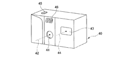
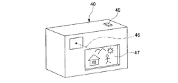
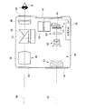
図11〜13は、本発明によるズームレンズをデジタルカメラの撮影光学系41に組み込んだ構成の概念図を示す。図11はデジタルカメラ40の外観を示す前方斜視図、図12は同後方斜視図、図13はデジタルカメラ40の構成を示す断面図である。
[Second Embodiment]
Next, a camera according to a second embodiment of the present invention will be described.
The zoom lens according to the first embodiment of the present invention as described above is an imaging device, particularly a digital camera or video, which forms an object image with the zoom lens and receives the image with an electronic image sensor such as a CCD. It can be used for a camera, a personal computer which is an example of an information processing device, a telephone, particularly a mobile phone which is convenient to carry. The embodiment is illustrated below.
11 to 13 are conceptual diagrams of a configuration in which the zoom lens according to the present invention is incorporated in a photographing
デジタルカメラ40(カメラ)は、この例の場合、撮影用光路42を有する撮影光学系41(ズームレンズ)、ファインダー用光路44を有するファインダー光学系43、シャッター45、フラッシュ46、液晶表示モニター47等を含み、デジタルカメラ40の上部に配置されたシャッター45を押圧すると、それに連動して撮影光学系41、例えば第1の実施形態のズームレンズ100、101、102、103、104などを通して撮影が行われる。撮影光学系41によって形成された物体像が、光学的ローパスフィルタF1、カバーガラスGLを介してCCD49(撮像素子)の撮像面上に形成される。このCCD49で受光された物体像は、処理手段51を介し、電子画像としてカメラ背面に設けられた液晶表示モニター47に表示される。また、この処理手段51には記録手段52が接続され、撮影された電子画像を記録することもできる。なお、この記録手段52は処理手段51と別体に設けてもよいし、フロッピー(登録商標)ディスクやメモリーカード、MO等により電子的に記録書込を行うように構成してもよい。また、CCD49に代わって銀塩フィルムを配置した銀塩カメラとして構成してもよい。
In this example, the digital camera 40 (camera) includes a photographing optical system 41 (zoom lens) having a photographing
さらに、ファインダー用光路44上にはファインダー用対物光学系53が配置してある。このファインダー用対物光学系53によって形成された物体像は、像正立部材であるポロプリズム55の視野枠57上に形成される。このポリプリズム55の後方には、正立正像にされた像を観察者眼球Eに導く接眼光学系59が配置されている。なお、撮影光学系41及びファインダー用対物光学系53の入射側、接眼光学系59の射出側にそれぞれカバー部材50が配置されている。
Further, a finder objective
このように構成されたデジタルカメラ40は、撮影光学系41が広画角で高変倍比であり、収差が良好で、明るく、フィルター等が配置できるバックフォーカスの大きなズームレンズであるので、高性能・低コスト化が実現できる。
The
なお、図13の例では、カバー部材50として平行平面板を配置しているが、パワーを持ったレンズを用いてもよい。
In the example of FIG. 13, a parallel plane plate is disposed as the
100、101、102、103、104 ズームレンズ
G1 第1レンズ群
G2 第2レンズ群
G3 第3レンズ群
S 開口絞り
F 平行平板群
F1 光学的ローパスフィルタ
I 像面
L1、L10、L20、L30、L40 負レンズ(第1レンズ群の負の第1レンズ)
L2、L11、L21、L31、L41 正レンズ(第1レンズ群の正の第2レンズ)
L3、L12、L22、L32、L42 正レンズ(第2レンズ群の正の第1レンズ)
L4、L13、L23、L33、L43 接合レンズ
L5、L14、L24、L34、L44 正レンズ(第2レンズ群の正の第2レンズ)
L6、L15、L25、L35、L45 負レンズ(第2レンズ群の負の第3レンズ)
L7、L16、L26、L36 正レンズ(第2レンズ群の正の第4レンズ)
L8、L17、L27、L37、L46 正レンズ(第3レンズ群の正の単レンズ)
40 デジタルカメラ(カメラ)
41 撮像光学系(ズームレンズ)
49 CCD(撮像素子)
100, 101, 102, 103, 104 Zoom lens G1 First lens group G2 Second lens group G3 Third lens group S Aperture stop F Parallel plate group F1 Optical low-pass filter I Image planes L1, L10, L20, L30, L40 Negative lens (negative first lens in the first lens group)
L2, L11, L21, L31, L41 Positive lens (positive second lens in the first lens group)
L3, L12, L22, L32, L42 Positive lens (positive first lens in the second lens group)
L4, L13, L23, L33, L43 Joint lens L5, L14, L24, L34, L44 Positive lens (positive second lens in the second lens group)
L6, L15, L25, L35, L45 Negative lens (negative third lens of the second lens group)
L7, L16, L26, L36 Positive lens (positive fourth lens in the second lens group)
L8, L17, L27, L37, L46 Positive lens (positive single lens in the third lens group)
40 Digital camera (camera)
41 Imaging optical system (zoom lens)
49 CCD (imaging device)
Claims (10)
前記第1レンズ群が、物体側より順に、負の第1レンズ、正の第2レンズから構成され、少なくとも1面の非球面を有し、
前記第2レンズ群が、物体側より順に、正の第1レンズ、正の第2レンズ、負の第3レンズを備え、前記正の第2レンズおよび前記負の第3レンズが互いに接合されて、物体側に凸面を向けたメニスカス形状の接合レンズをなす構成とされ、該接合レンズの接合面を除く少なくとも2面に非球面を有し、
前記第3レンズ群が、球面のみからなる正の単レンズから構成され、
無限遠物点合焦時に広角端から望遠端へ変倍する際、前記第1レンズ群が像側に凸の軌跡で移動し、前記第2レンズ群が物体側へのみ移動し、前記第3レンズ群が第2レンズ群とは異なる量で移動しかつ合焦のために可動とされ、
以下の条件式(1)、(2)、(5)、(6)’、(7)’を満足することを特徴とするズームレンズ。
2.3<Lt/f2<3.7 ・・・(1)
1.15<|f1/f2|<2.0 ・・・(2)
0.3<R 23R /R 22F <1.0 ・・・(5)
0.9≦f 2 /R 23F <1.4 ・・・(6)’
1.69≦|f 2 /f 23 |<3.0 ・・・(7)’
ただし、Ltはズームレンズの望遠端での最も物体側のレンズ面から結像面までの距離、f2は前記第2レンズ群の焦点距離、f1は前記第1レンズ群の焦点距離、R 22F は第2レンズ群の正の第2レンズの物体側の面の光軸近傍の曲率半径、R 23R は、第2レンズ群の負の第3レンズの最も像側の面の光軸近傍の曲率半径、R 23F は第2レンズ群の接合レンズの接合面の光軸近傍の曲率半径、f 23 は第2レンズ群の負の第3レンズの焦点距離である。 In order from the object side, a first lens group having a negative refractive power, a second lens group having a positive refractive power, and a third lens group having a positive refractive power,
The first lens group includes, in order from the object side, a negative first lens and a positive second lens, and has at least one aspheric surface.
The second lens group includes, in order from the object side, a positive first lens, a positive second lens, and a negative third lens, and the positive second lens and the negative third lens are cemented with each other. A meniscus cemented lens having a convex surface facing the object side, and has at least two surfaces other than the cemented surface of the cemented lens, and has an aspheric surface,
The third lens group is composed of a positive single lens consisting only of a spherical surface,
When zooming from the wide-angle end to the telephoto end when focusing on an object point at infinity, the first lens group moves along a locus convex toward the image side, the second lens group moves only toward the object side, and the third The lens group moves by a different amount than the second lens group and is movable for focusing;
A zoom lens characterized by satisfying the following conditional expressions (1), (2) , (5), (6) ′, and (7) ′ .
2.3 <L t / f 2 <3.7 (1)
1.15 <| f 1 / f 2 | <2.0 (2)
0.3 <R 23R / R 22F <1.0 (5)
0.9 ≦ f 2 / R 23F <1.4 (6) ′
1.69 ≦ | f 2 / f 23 | <3.0 (7) ′
Where L t is the distance from the lens surface closest to the object side to the imaging surface at the telephoto end of the zoom lens, f 2 is the focal length of the second lens group, f 1 is the focal length of the first lens group , R 22F is a radius of curvature in the vicinity of the optical axis of the object side surface of the positive second lens in the second lens group, and R 23R is in the vicinity of the optical axis of the most image side surface of the negative third lens in the second lens group. R 23F is the radius of curvature near the optical axis of the cemented surface of the cemented lens of the second lens group , and f 23 is the focal length of the negative third lens of the second lens group .
0.29<fW/f3<0.6 ・・・(3)
ただし、fWは広角端でのズームレンズ全系の焦点距離、f3は前記第3レンズ群の焦点距離である。 The zoom lens according to claim 1, wherein the following conditional expression (3) is satisfied.
0.29 <f W / f 3 <0.6 (3)
Here, f W is the focal length of the entire zoom lens system at the wide angle end, and f 3 is the focal length of the third lens group.
Priority Applications (2)
| Application Number | Priority Date | Filing Date | Title |
|---|---|---|---|
| JP2004136908A JP4540387B2 (en) | 2004-04-30 | 2004-04-30 | Zoom lens and imaging device |
| US11/114,096 US7092170B2 (en) | 2004-04-30 | 2005-04-26 | Zoom lens and image pickup apparatus |
Applications Claiming Priority (1)
| Application Number | Priority Date | Filing Date | Title |
|---|---|---|---|
| JP2004136908A JP4540387B2 (en) | 2004-04-30 | 2004-04-30 | Zoom lens and imaging device |
Publications (2)
| Publication Number | Publication Date |
|---|---|
| JP2005316333A JP2005316333A (en) | 2005-11-10 |
| JP4540387B2 true JP4540387B2 (en) | 2010-09-08 |
Family
ID=35443806
Family Applications (1)
| Application Number | Title | Priority Date | Filing Date |
|---|---|---|---|
| JP2004136908A Expired - Fee Related JP4540387B2 (en) | 2004-04-30 | 2004-04-30 | Zoom lens and imaging device |
Country Status (1)
| Country | Link |
|---|---|
| JP (1) | JP4540387B2 (en) |
Families Citing this family (4)
| Publication number | Priority date | Publication date | Assignee | Title |
|---|---|---|---|---|
| JP5433958B2 (en) | 2008-03-03 | 2014-03-05 | 株式会社ニコン | Zoom lens and optical apparatus provided with the same |
| JP4697555B2 (en) * | 2008-11-19 | 2011-06-08 | ソニー株式会社 | Zoom lens and imaging device |
| JP4697556B2 (en) | 2008-11-21 | 2011-06-08 | ソニー株式会社 | Zoom lens and imaging device |
| JP6296803B2 (en) * | 2014-01-22 | 2018-03-20 | キヤノン株式会社 | Optical system and imaging apparatus having the same |
Citations (7)
| Publication number | Priority date | Publication date | Assignee | Title |
|---|---|---|---|---|
| JP2002196240A (en) * | 2000-12-25 | 2002-07-12 | Konica Corp | Zoom lens |
| JP2002277740A (en) * | 2001-03-19 | 2002-09-25 | Asahi Optical Co Ltd | Zoom lens system |
| JP2002372667A (en) * | 2001-06-14 | 2002-12-26 | Konica Corp | Zoom lens |
| JP2003222797A (en) * | 2002-01-29 | 2003-08-08 | Olympus Optical Co Ltd | Imaging apparatus |
| JP2004004765A (en) * | 2002-04-19 | 2004-01-08 | Pentax Corp | Zoom lens system |
| JP2004061675A (en) * | 2002-07-26 | 2004-02-26 | Canon Inc | Zoom lens |
| JP2004239974A (en) * | 2003-02-03 | 2004-08-26 | Nikon Corp | Zoom lens |
-
2004
- 2004-04-30 JP JP2004136908A patent/JP4540387B2/en not_active Expired - Fee Related
Patent Citations (7)
| Publication number | Priority date | Publication date | Assignee | Title |
|---|---|---|---|---|
| JP2002196240A (en) * | 2000-12-25 | 2002-07-12 | Konica Corp | Zoom lens |
| JP2002277740A (en) * | 2001-03-19 | 2002-09-25 | Asahi Optical Co Ltd | Zoom lens system |
| JP2002372667A (en) * | 2001-06-14 | 2002-12-26 | Konica Corp | Zoom lens |
| JP2003222797A (en) * | 2002-01-29 | 2003-08-08 | Olympus Optical Co Ltd | Imaging apparatus |
| JP2004004765A (en) * | 2002-04-19 | 2004-01-08 | Pentax Corp | Zoom lens system |
| JP2004061675A (en) * | 2002-07-26 | 2004-02-26 | Canon Inc | Zoom lens |
| JP2004239974A (en) * | 2003-02-03 | 2004-08-26 | Nikon Corp | Zoom lens |
Also Published As
| Publication number | Publication date |
|---|---|
| JP2005316333A (en) | 2005-11-10 |
Similar Documents
| Publication | Publication Date | Title |
|---|---|---|
| JP4938068B2 (en) | Electronic imaging device | |
| JP5111789B2 (en) | Zoom lens and electronic imaging apparatus including the same | |
| JP4863733B2 (en) | Zoom lens and imaging apparatus using the same | |
| JP4900924B2 (en) | Zoom lens and electronic imaging apparatus using the same | |
| JP4901270B2 (en) | Zoom lens | |
| JP4900923B2 (en) | Zoom lens and electronic imaging apparatus using the same | |
| JP6238103B2 (en) | Imaging optical system, camera device, and portable information terminal device | |
| JP2006098686A (en) | Zoom lens and electronic imaging apparatus using the same | |
| JP5295715B2 (en) | Imaging optical system and electronic imaging apparatus having the same | |
| JP2000321499A (en) | Zoom lens | |
| JP4766929B2 (en) | Image pickup apparatus having an optical path folding zoom lens | |
| JP4690052B2 (en) | Zoom lens and imaging apparatus using the same | |
| US7423813B2 (en) | Zoom lens system and image pickup apparatus including the same | |
| JP4512359B2 (en) | Camera with zoom lens | |
| JP2011232620A (en) | Imaging optical system and electronic imaging apparatus equipped with the same | |
| JP4245783B2 (en) | Zoom lens and image pickup apparatus equipped with zoom lens | |
| JP4813102B2 (en) | Zoom lens and electronic imaging apparatus using the same | |
| JP4866120B2 (en) | Zoom lens and imaging apparatus having the same | |
| JP2003107356A (en) | Optical path bending zoom optical system | |
| JP4948027B2 (en) | Zoom lens and image pickup apparatus including the same | |
| JP2006194975A (en) | Zoom lens and imaging apparatus using the same | |
| JP2006098685A (en) | Zoom lens and electronic imaging apparatus using the same | |
| JP4884054B2 (en) | Zoom lens | |
| JP4540387B2 (en) | Zoom lens and imaging device | |
| JP2011247955A (en) | Imaging optical system and electronic imaging device having the same |
Legal Events
| Date | Code | Title | Description |
|---|---|---|---|
| A621 | Written request for application examination |
Free format text: JAPANESE INTERMEDIATE CODE: A621 Effective date: 20070208 |
|
| A977 | Report on retrieval |
Free format text: JAPANESE INTERMEDIATE CODE: A971007 Effective date: 20100316 |
|
| A131 | Notification of reasons for refusal |
Free format text: JAPANESE INTERMEDIATE CODE: A131 Effective date: 20100323 |
|
| A521 | Written amendment |
Free format text: JAPANESE INTERMEDIATE CODE: A523 Effective date: 20100521 |
|
| A521 | Written amendment |
Free format text: JAPANESE INTERMEDIATE CODE: A821 Effective date: 20100524 |
|
| TRDD | Decision of grant or rejection written | ||
| A01 | Written decision to grant a patent or to grant a registration (utility model) |
Free format text: JAPANESE INTERMEDIATE CODE: A01 Effective date: 20100615 |
|
| A01 | Written decision to grant a patent or to grant a registration (utility model) |
Free format text: JAPANESE INTERMEDIATE CODE: A01 |
|
| A61 | First payment of annual fees (during grant procedure) |
Free format text: JAPANESE INTERMEDIATE CODE: A61 Effective date: 20100622 |
|
| R151 | Written notification of patent or utility model registration |
Ref document number: 4540387 Country of ref document: JP Free format text: JAPANESE INTERMEDIATE CODE: R151 |
|
| FPAY | Renewal fee payment (event date is renewal date of database) |
Free format text: PAYMENT UNTIL: 20130702 Year of fee payment: 3 |
|
| S531 | Written request for registration of change of domicile |
Free format text: JAPANESE INTERMEDIATE CODE: R313531 |
|
| R350 | Written notification of registration of transfer |
Free format text: JAPANESE INTERMEDIATE CODE: R350 |
|
| LAPS | Cancellation because of no payment of annual fees |