JP4540381B2 - Composite structural member for fusion reactor and method of manufacturing the same - Google Patents
Composite structural member for fusion reactor and method of manufacturing the same Download PDFInfo
- Publication number
- JP4540381B2 JP4540381B2 JP2004110035A JP2004110035A JP4540381B2 JP 4540381 B2 JP4540381 B2 JP 4540381B2 JP 2004110035 A JP2004110035 A JP 2004110035A JP 2004110035 A JP2004110035 A JP 2004110035A JP 4540381 B2 JP4540381 B2 JP 4540381B2
- Authority
- JP
- Japan
- Prior art keywords
- copper
- tungsten
- composite structural
- plasma
- structural member
- Prior art date
- Legal status (The legal status is an assumption and is not a legal conclusion. Google has not performed a legal analysis and makes no representation as to the accuracy of the status listed.)
- Expired - Fee Related
Links
Images


Classifications
-
- G—PHYSICS
- G21—NUCLEAR PHYSICS; NUCLEAR ENGINEERING
- G21B—FUSION REACTORS
- G21B1/00—Thermonuclear fusion reactors
-
- C—CHEMISTRY; METALLURGY
- C22—METALLURGY; FERROUS OR NON-FERROUS ALLOYS; TREATMENT OF ALLOYS OR NON-FERROUS METALS
- C22C—ALLOYS
- C22C27/00—Alloys based on rhenium or a refractory metal not mentioned in groups C22C14/00 or C22C16/00
- C22C27/04—Alloys based on tungsten or molybdenum
-
- B—PERFORMING OPERATIONS; TRANSPORTING
- B32—LAYERED PRODUCTS
- B32B—LAYERED PRODUCTS, i.e. PRODUCTS BUILT-UP OF STRATA OF FLAT OR NON-FLAT, e.g. CELLULAR OR HONEYCOMB, FORM
- B32B15/00—Layered products comprising a layer of metal
- B32B15/01—Layered products comprising a layer of metal all layers being exclusively metallic
- B32B15/013—Layered products comprising a layer of metal all layers being exclusively metallic one layer being formed of an iron alloy or steel, another layer being formed of a metal other than iron or aluminium
- B32B15/015—Layered products comprising a layer of metal all layers being exclusively metallic one layer being formed of an iron alloy or steel, another layer being formed of a metal other than iron or aluminium the said other metal being copper or nickel or an alloy thereof
-
- G—PHYSICS
- G21—NUCLEAR PHYSICS; NUCLEAR ENGINEERING
- G21B—FUSION REACTORS
- G21B1/00—Thermonuclear fusion reactors
- G21B1/11—Details
- G21B1/13—First wall; Blanket; Divertor
-
- Y—GENERAL TAGGING OF NEW TECHNOLOGICAL DEVELOPMENTS; GENERAL TAGGING OF CROSS-SECTIONAL TECHNOLOGIES SPANNING OVER SEVERAL SECTIONS OF THE IPC; TECHNICAL SUBJECTS COVERED BY FORMER USPC CROSS-REFERENCE ART COLLECTIONS [XRACs] AND DIGESTS
- Y02—TECHNOLOGIES OR APPLICATIONS FOR MITIGATION OR ADAPTATION AGAINST CLIMATE CHANGE
- Y02E—REDUCTION OF GREENHOUSE GAS [GHG] EMISSIONS, RELATED TO ENERGY GENERATION, TRANSMISSION OR DISTRIBUTION
- Y02E30/00—Energy generation of nuclear origin
- Y02E30/10—Nuclear fusion reactors
-
- Y—GENERAL TAGGING OF NEW TECHNOLOGICAL DEVELOPMENTS; GENERAL TAGGING OF CROSS-SECTIONAL TECHNOLOGIES SPANNING OVER SEVERAL SECTIONS OF THE IPC; TECHNICAL SUBJECTS COVERED BY FORMER USPC CROSS-REFERENCE ART COLLECTIONS [XRACs] AND DIGESTS
- Y10—TECHNICAL SUBJECTS COVERED BY FORMER USPC
- Y10S—TECHNICAL SUBJECTS COVERED BY FORMER USPC CROSS-REFERENCE ART COLLECTIONS [XRACs] AND DIGESTS
- Y10S376/00—Induced nuclear reactions: processes, systems, and elements
- Y10S376/90—Particular material or material shapes for fission reactors
- Y10S376/904—Moderator, reflector, or coolant materials
- Y10S376/906—Metal
-
- Y—GENERAL TAGGING OF NEW TECHNOLOGICAL DEVELOPMENTS; GENERAL TAGGING OF CROSS-SECTIONAL TECHNOLOGIES SPANNING OVER SEVERAL SECTIONS OF THE IPC; TECHNICAL SUBJECTS COVERED BY FORMER USPC CROSS-REFERENCE ART COLLECTIONS [XRACs] AND DIGESTS
- Y10—TECHNICAL SUBJECTS COVERED BY FORMER USPC
- Y10T—TECHNICAL SUBJECTS COVERED BY FORMER US CLASSIFICATION
- Y10T428/00—Stock material or miscellaneous articles
- Y10T428/12—All metal or with adjacent metals
- Y10T428/12014—All metal or with adjacent metals having metal particles
- Y10T428/12028—Composite; i.e., plural, adjacent, spatially distinct metal components [e.g., layers, etc.]
- Y10T428/12063—Nonparticulate metal component
-
- Y—GENERAL TAGGING OF NEW TECHNOLOGICAL DEVELOPMENTS; GENERAL TAGGING OF CROSS-SECTIONAL TECHNOLOGIES SPANNING OVER SEVERAL SECTIONS OF THE IPC; TECHNICAL SUBJECTS COVERED BY FORMER USPC CROSS-REFERENCE ART COLLECTIONS [XRACs] AND DIGESTS
- Y10—TECHNICAL SUBJECTS COVERED BY FORMER USPC
- Y10T—TECHNICAL SUBJECTS COVERED BY FORMER US CLASSIFICATION
- Y10T428/00—Stock material or miscellaneous articles
- Y10T428/12—All metal or with adjacent metals
- Y10T428/12493—Composite; i.e., plural, adjacent, spatially distinct metal components [e.g., layers, joint, etc.]
- Y10T428/12771—Transition metal-base component
- Y10T428/12806—Refractory [Group IVB, VB, or VIB] metal-base component
- Y10T428/12826—Group VIB metal-base component
- Y10T428/1284—W-base component
-
- Y—GENERAL TAGGING OF NEW TECHNOLOGICAL DEVELOPMENTS; GENERAL TAGGING OF CROSS-SECTIONAL TECHNOLOGIES SPANNING OVER SEVERAL SECTIONS OF THE IPC; TECHNICAL SUBJECTS COVERED BY FORMER USPC CROSS-REFERENCE ART COLLECTIONS [XRACs] AND DIGESTS
- Y10—TECHNICAL SUBJECTS COVERED BY FORMER USPC
- Y10T—TECHNICAL SUBJECTS COVERED BY FORMER US CLASSIFICATION
- Y10T428/00—Stock material or miscellaneous articles
- Y10T428/12—All metal or with adjacent metals
- Y10T428/12493—Composite; i.e., plural, adjacent, spatially distinct metal components [e.g., layers, joint, etc.]
- Y10T428/12771—Transition metal-base component
- Y10T428/12861—Group VIII or IB metal-base component
- Y10T428/12903—Cu-base component
Description
本発明は、少なくとも、タングステンまたはタングステン含有量が90重量%より高いタングステン合金からなるプラズマ対向領域と、熱伝導率が250W/mKより高く、平均結晶粒径が100μmより大きい銅または銅合金からなる熱放散領域と、高融点金属と銅との複合金属からなる中間に存在する領域とからなる、核融合炉のための高度に耐熱性の複合構造部材に関する。 The present invention comprises at least a plasma facing region made of tungsten or a tungsten alloy having a tungsten content higher than 90% by weight, and copper or a copper alloy having a thermal conductivity higher than 250 W / mK and an average crystal grain size larger than 100 μm. The present invention relates to a highly heat-resistant composite structural member for a fusion reactor comprising a heat dissipation region and an intermediate region formed of a composite metal of a refractory metal and copper.
核融合炉の定常的な運転では、最高10MW/m2もの電力潮流が第一壁構造部材の表面領域にかかるものと予期される。この第一壁構造部材はPFC(plasma facing components=プラスマ対向構造部材)とも呼ばれる。プラズマ崩壊に際しては、露出箇所では、ほんの数ミリ秒の間に約20GJが放出される可能性がある。最大のエネルギー密度となる領域、たとえばダイバータ、バッフルおよびリミッタ領域において使用するために特別に設計されるPFCの開発は、核融合研究の結果を技術的に実用化する際のキーとなる要素である。 In steady operation of the fusion reactor, a power flow of up to 10 MW / m 2 is expected to be applied to the surface area of the first wall structural member. This first wall structural member is also called PFC (plasma facing components = plasma facing structural member). Upon plasma decay, approximately 20 GJ may be released in a few milliseconds at exposed locations. The development of PFCs specially designed for use in areas with the highest energy density, such as diverters, baffles and limiters, is a key element in the practical application of the results of fusion research. .
PFC構造部材に適用できる材料としての要件は多種多様で、それぞれの要件の間で矛盾があることも多い。高熱伝導率、高融点、低蒸気圧、良好な耐熱衝撃性および加工適合性などの物理的および機械的性質に加えて、核融合において使用するとなると、特殊な性能も要求され、そのようなものの例を挙げれば、大量の中性子照射下でも放射化および核種変換が低いこと、トリチウムの連続吸収が低いこと、プラズマイオンおよび中性子粒子によるエロージョンが少ないこと、アーク放電およびホットスポットのような局所的な作用によるスパッタ速度およびエロージョンが低いこと、さらには、特性放射によるコアプラズマの冷却が低いことなどがある。 There are a wide variety of requirements as materials applicable to PFC structural members, and there are often contradictions between the requirements. In addition to physical and mechanical properties such as high thermal conductivity, high melting point, low vapor pressure, good thermal shock resistance and workability, special performance is also required when used in nuclear fusion. Examples include low activation and radionuclide conversion even under large neutron irradiation, low continuous tritium absorption, low erosion by plasma ions and neutron particles, local discharge such as arc discharge and hot spots. Sputtering speed and erosion due to action are low, and further, cooling of the core plasma due to characteristic radiation is low.
負荷条件に応じて、PFCとして好適な材料には、ベリリウム、炭素繊維強化炭素(CFC)およびタングステンがある。タングステンは、比較的プラズマ温度が低く、粒子密度が高いことが多い第一壁に使用するのには特に適している。タングステンは、たとえば高い熱伝導率(室温で165W/mK)などのように、非常に良好な熱的性質を有している。さらに、高融点、低トリチウム吸収能、低真空ガス速度および低スパッタ速度などの面から、タングステンはPFCに使用するために特に優れている。エネルギー密度の極めて高い領域から効果的に熱を除去する目的で、PFCは積極的に冷却しなければならない。これは、冷却媒体で貫流される銅構造部材を採用することによって達成することが可能で、それをヒートシンクとしてタングステン構造部材と組み合わせる。充分に高い機械的安定性と剛性を得るためには、銅ヒートシンクを、高度に剛性の高い金属構造材料と結合させるのが有利である。オーステナイト鋼および粒子強化銅合金、たとえば時効硬化Cr−Zr合金化銅合金(Cu−Cr−Zr)またはODS(oxide−dispersion−strengthened=酸化物分散強化)銅材料(たとえば、Cu−Al2O3、Cu−ZrO2、Cu−Y2O3、Cu−希土類酸化物)などは、この種の補強要素としては好ましいものである。高エネルギー密度領域において使用されるPFCの設計には、2種類のものが考えられる。いわゆるフラットタイルにおいては、個々の材料の間の移行領域は近似的に平面状に形成される。モノブロック構造部材の場合には、冷却媒体で貫流される、たとえば時効硬化銅合金またはODS銅でできている管によって充分な構造的安定性と剛性が与えられている。外側に向かっては、フラットタイルの場合と同様な配置でその他の材料を配列する。タングステンセグメントは、冷却管を取り巻く立方体の形状をとっているが、そこでは、柔軟性があって延性のある材料、好ましくは低酸素含量の純銅(OFHC銅)からなる緩衝層が、冷却管とタングステンセグメントとの間に配置される。
Depending on loading conditions, suitable materials for PFC include beryllium, carbon fiber reinforced carbon (CFC) and tungsten. Tungsten is particularly suitable for use on the first wall, which has a relatively low plasma temperature and often has a high particle density. Tungsten has very good thermal properties, such as high thermal conductivity (165 W / mK at room temperature). Furthermore, tungsten is particularly excellent for use in PFC from the standpoints of high melting point, low tritium absorption capacity, low vacuum gas rate and low sputtering rate. The PFC must be actively cooled in order to effectively remove heat from areas with very high energy density. This can be accomplished by employing a copper structural member that is flowed through with a cooling medium, which is combined with the tungsten structural member as a heat sink. In order to obtain sufficiently high mechanical stability and rigidity, it is advantageous to bond the copper heat sink with a highly rigid metal structural material. Austenitic steels and particle-reinforced copper alloy, for example, age hardening Cr-Zr alloy copper alloy (Cu-Cr-Zr) or ODS (oxide-dispersion-strengthened = oxide dispersion strengthened) copper material (e.g., Cu-Al 2 O 3 , Cu-ZrO 2, Cu- Y 2
たとえばフラットタイルまたはモノブロック構造部材のような、核融合炉のための複合部材を製造する際に生じる特別な難点は、タングステンと銅とが非常に異なった熱膨張挙動を示すことである。すなわち室温におけるタングステンの熱膨張率が4.5×10⁻⁶K-1であるのに対して、銅のそれは16.6×10⁻⁶K-1である。 A particular difficulty that arises when producing composite components for fusion reactors, such as flat tile or monoblock structural members, is that tungsten and copper exhibit very different thermal expansion behavior. That is, the thermal expansion coefficient of tungsten at room temperature is 4.5 × 10 −6 K −1 , whereas that of copper is 16.6 × 10 −6 K −1 .
タングステンを銅に接合させるのに推奨される技術としては、ろう付け、拡散溶接、バックキャスティングがある。拡散溶接は、特許文献1に記載されているようにして、熱間静水圧加圧法(hot isostatic pressing=HIP)を使用して実施することができる。上記のプロセスは、約700〜1300℃の温度範囲内で実施される。冷却時に、タングステンと銅の熱膨張率の差があるために、結合部の近傍に応力が集中することになる。しかしながら、PFCの使用に際しても、それらが周期的な熱負荷にさらされると、応力がさらに加わる。これらの応力が、タングステンと銅の界面におけるひび割れや分離の原因となる可能性がある。そのことによって熱放散を妨げられ、その結果複合構造部材が溶融する危険性がもたらされる。積極的に冷却している銅ヒートシンクに形状的にぴったりと接合させたプラズマ対向タングステンセグメントからなる、界面領域で低い接合応力を示すような複合構造部材を実現させる目的の、積極的な開発計画が開始されていて、そのいくつかはすでに実施されている。
Recommended techniques for joining tungsten to copper include brazing, diffusion welding, and backcasting. Diffusion welding can be performed using a hot isostatic pressing method (HIP) as described in
個々では辺や直径が数ミリメートルの小さな立方体または棒状物の集成物としてのタングステンセグメントを設計することによって、応力をかなり減少させることが可能となったが、この場合はその立方体や棒状物は銅セグメントの中を貫通させる。この形式のセグメンテーションによって、接合プロセスおよび周期的な運転からくる熱応力は、減少する。しかしながら、この設計は、タングステンと銅との界面における疲労クラックの危険性を増大させている。 Individually, it was possible to significantly reduce stress by designing tungsten segments as small cubes or rod assemblies with sides and diameters of a few millimeters, but in this case the cubes and rods were copper. Penetrate through the segment. This type of segmentation reduces the thermal stresses resulting from the joining process and periodic operation. However, this design increases the risk of fatigue cracks at the tungsten-copper interface.
タングステンと銅セグメントの間に段階をつけた中間層を組み込むことによって、界面における張力を減らそうとする試みが多数なされてきた。たとえば、特許文献2には、タングステンと銅とのFGM(functionally graded material=機能的に段階をつけた材料)を製造するための方法が記載されているが、そこでは、たとえば熱プラズマスプレー法によって製造した多孔度に段階をつけたタングステンセグメントに銅を溶浸させている。
Many attempts have been made to reduce the tension at the interface by incorporating a graded interlayer between the tungsten and copper segments. For example,
さらに特許文献3には、熱プラズマスプレー法を使用してタングステンと銅セグメントの間で段階をつけた中間層を得る製造プロセスが記載されている。特許文献2に記載されているプロセスとは対照的に、銅相も熱プラズマスプレー法によって分離されており、そこでは添加された特殊な粉末ブレンドが、対応するタングステンと銅の比率を含んでいる。タングステンとFGMの間にある薄い金属膜が接合を促進している。
Further,
特許文献3にはさらに、タングステンと銅ヒートシンクの間に、銅とタングステンのブレンドからなる層をろう付けまたは拡散接合によって装入する試みも記載されている。しかしながら、熱膨張率における差が大きすぎ、この文献には、それ以上詳しい説明はされていない。
特許文献2および特許文献3の両方に記載されている製造プロセスは、熱誘導クラックに対する顕著に高い抵抗性を示す積層部材を製造するものであると考えられる。
The manufacturing processes described in both
しかしながら、これらの特許に記載されたプロセスの欠点は、そのプロセスが複雑で、その結果、記載された方法で製造された部材が、非常に高価となることである。それに加えて、プロセス技術上の制約から、上記の技術が適用できるのは、フラットタイル構造だけに限られる。一般的に言って、形状的な理由から、それらの技術によってモノブロック形状を製造することは不可能である。 However, a disadvantage of the processes described in these patents is that the process is complex and, as a result, parts manufactured by the described method are very expensive. In addition, the above technique can be applied only to a flat tile structure because of limitations in process technology. Generally speaking, for geometric reasons, it is impossible to produce monoblock shapes by these techniques.
本発明の課題は、少なくとも一部はタングステンまたはタングステン合金と銅または銅合金とからなり、特に熱疲労に関して充分な効力を有していて、コスト面で経済的に製造することが可能であり、モノブロック形状とするのにも適した、核融合炉のための複合構造部材を製造することにある。 The subject of the present invention is at least partly composed of tungsten or a tungsten alloy and copper or a copper alloy, has a sufficient effect especially on thermal fatigue, and can be produced economically in terms of cost, The object is to produce a composite structural member for a nuclear fusion reactor, which is also suitable for a monoblock shape.
この課題を解決するために、この発明によれば、核融合炉のための耐熱性の複合構造部材(1)であって、この複合構造部材(1)は、少なくとも、核融合プラズマと直接対面する炉壁部材であってタングステンまたはタングステン含有量が90重量%より高いタングステン合金からなるプラズマ対向部材(2)と、前記プラズマ対向部材に隣接しプラズマの熱を外部に伝達するための構成部材であって熱伝導率が250W/mKより高くかつ平均結晶粒径が100μmより大きい銅または銅合金からなる熱放散用部材(4)と、前記プラズマ対向部材(2)と前記熱放散用部材(4)との間に存在し、1800℃を超える融点を有する周期律表の第IVb族および第Vb族の元素である高融点金属と銅との複合金属からなる中間部材(3)とからなり、前記中間部材(3)は、0.1mmより大かつ4mmより小の厚さを有し、銅と高融点金属との濃度分布が一様であって、銅成分が10〜40容積%、残部が高融点金属であることを特徴とする。 To solve this problem, according to the present invention, a composite structural member of heat resistance for the fusion reactor (1), the composite structural member (1) is at least directly faces the fusion plasma A plasma facing member (2) comprising a furnace wall member made of tungsten or a tungsten alloy having a tungsten content higher than 90% by weight, and a component for transferring plasma heat to the outside adjacent to the plasma facing member A heat dissipating member (4) made of copper or a copper alloy having a thermal conductivity higher than 250 W / mK and an average crystal grain size larger than 100 μm, the plasma facing member (2) and the heat dissipating member (4 ) exists between the, the intermediate member composed of a composite metal with a high melting point metal and copper is at the IV b and group V b group element of the periodic table having a melting point above 1800 ° C. (3) Rannahli, said intermediate member (3) has a large and small than 4mm thickness than 0.1 mm, the concentration distribution of copper and the refractory metal is a uniform, copper component is 10 to 40 volume %, The balance being a refractory metal .
高融点金属と銅との構造部材は、多くの産業用途で使用されており、例を挙げれば、エレクトロニクスパッケージにおけるヒートシンクまたはヒートスプレッダーなどである。高融点金属とは、1800℃を超える融点を有する周期律表の第IVb族および第Vb族の元素で、特に金属のNb、Ta、Cr、MoおよびWである。 Structural members of refractory metals and copper are used in many industrial applications, such as heat sinks or heat spreaders in electronic packages. The refractory metal in the IV b and Group V b group element of the periodic table having a melting point above 1800 ° C., in particular metals Nb, Ta, Cr, Mo and W.
核融合炉のためのタングステンと銅との複合構造部材における応力は、FGMを使用する以外には減少させることはできないという、広く一般に言われている考え方に反して、驚くべきことには実験で明らかになったのは、高融点金属と銅との材料からなる中間相で、巨視的に一様な銅と高融点金属との濃度分布を有するものもまた有効に使用できるということである。巨視的に一様な濃度分布とは、濃度における微視的な差とは関わりなく、高融点金属と銅との複合金属の厚み全体を通しての濃度分布と定義する。濃度における微視的な差は、高融点金属と銅との複合材料中に常に現れるが、その理由は高融点金属と銅とはまったく溶け合わないか、あるいは互いにほんのわずかしか溶け合わないからである。したがって、互いに隣り合った銅と高融点金属相の領域は、5〜50μmの間の大きさにある。 Contrary to the widely accepted idea that stress in a composite structure of tungsten and copper for fusion reactors can only be reduced by using FGM, it is surprisingly experimental. What has become clear is that an intermediate phase composed of a material of a refractory metal and copper and having a macroscopically uniform concentration distribution of copper and refractory metal can also be used effectively. The macroscopically uniform concentration distribution is defined as the concentration distribution throughout the entire thickness of the composite metal of refractory metal and copper regardless of the microscopic difference in concentration. Microscopic differences in concentration always appear in refractory metal and copper composites because refractory metal and copper do not dissolve at all or only slightly to each other. is there. Therefore, the area | region of the copper and refractory metal phase which adjoined mutually has a magnitude | size between 5-50 micrometers.
境界領域における応力の効果的な削減は、高融点金属と銅との複合金属からなる層の厚みが少なくとも0.1mmの場合にのみ、達成できる。より薄い層では、充分な応力の削減はできない。それに対して厚みが4mm以上もあると、分離抵抗性および熱的に誘導される疲労クラックに対する抵抗性の点では複合部分の効力を損なうことはないが、高融点金属と銅との複合金属の熱伝導率が低いために熱放散が低下してしまい、その結果複合部分の機能に関する信頼性が確保できなくなってしまう。 Effective reduction of stress in the boundary region can be achieved only when the thickness of the layer made of the composite metal of refractory metal and copper is at least 0.1 mm. Thinner layers do not provide sufficient stress reduction. On the other hand, if the thickness is 4 mm or more, it does not impair the effectiveness of the composite part in terms of separation resistance and resistance to thermally induced fatigue cracks. Since heat conductivity is low, heat dissipation is reduced, and as a result, the reliability regarding the function of the composite portion cannot be ensured.
効力を充分とするためのさらなる前提条件として、高融点金属と銅との複合材料中での銅の成分が10〜40容積%でなければならない。銅の成分がこれより高いあるいは低いのいずれの場合も、プロセスの信頼性を充分に確保することはできない。さらに、この高融点金属と銅との複合金属は、高融点金属相が近似的に連続の骨格を形成するように製造しなければならない。 As a further prerequisite for sufficient efficacy, the copper component in the composite of refractory metal and copper must be 10-40 % by volume. Whether the copper component is higher or lower than this, sufficient process reliability cannot be ensured. Furthermore, the composite metal of the refractory metal and copper must be manufactured so that the refractory metal phase forms an approximately continuous skeleton.
この要件を満たすためには、多孔質な高融点金属体を銅で溶浸させるような、粉末冶金プロセスを使用して、高融点金属と銅との複合材料を製造する。多孔質な高融点金属体は、加圧成形しただけのものであっても、焼結したものであってもよい。近似的に連続の骨格を有する高融点金属と銅との複合材料はまた、粉末混合物または複合金属粉末を加圧し、焼結することによって製造できる。このようにして製造されるW−CuおよびMo−Cu複合材料のほかに、圧延または押出し成形したMo−Cu複合材料が特に有利であることがわかった。さらに、銅または銅合金セグメントは、熱的に誘導される応力を充分に減少させることができなければならい。「熱伝導率が250W/mKより大」という選択基準を設けるならば、合金元素の含有量が少なくしたがって降伏強さの弱い銅材料だけが使用できる。さらにその銅または銅合金セグメントは、効果的な応力削減を達成するためには、その平均粒子径が100μmより大きくなければならない。OFHC(oxygen−free−high−conductive=無酸素高導電性)銅を使用した銅または銅合金セグメントを、溶融によって高融点金属と銅との複合金属に接合させると、極めて有利となることが判った。このプロセスを使用すれば、銅/銅合金セグメント中の平均粒子径を常に100μmよりも大きくすることができる。同じプロセス相の間にタングステン/タングステン合金セグメントを高融点金属と銅との複合金属セグメントに銅相を溶融させることによって接合させることもできる。タングステンと高融点金属と銅の複合金属との間に厚みが0.005〜0.5mmの銅箔または銅シートを装入すると有利となることが判った。タングステンと銅との間の濡れを向上させるためには、タングステンと銅の両方に可溶であるかまたはこれら2種の材料と反応するような金属元素または合金を、たとえばタングステンセグメントをコーティングすることによって、装入することもまた有利となる。この目的には、鉄族金属の元素または合金、たとえばニッケルが適している。 To meet this requirement, a composite of refractory metal and copper is produced using a powder metallurgy process such that a porous refractory metal body is infiltrated with copper. The porous refractory metal body may be either pressure-molded or sintered. A composite of refractory metal and copper having an approximately continuous skeleton can also be produced by pressing and sintering a powder mixture or composite metal powder. In addition to the W-Cu and Mo-Cu composites produced in this way, it has been found that rolled or extruded Mo-Cu composites are particularly advantageous. In addition, the copper or copper alloy segment must be able to sufficiently reduce thermally induced stress. If the selection criterion “thermal conductivity is greater than 250 W / mK” is provided, only copper materials with low alloying element content and therefore low yield strength can be used. In addition, the copper or copper alloy segment must have an average particle size greater than 100 μm to achieve effective stress reduction. It has been found that it is extremely advantageous to bond a copper or copper alloy segment using OFHC (oxygen-free-high-conductive) copper to a composite metal of refractory metal and copper by melting. It was. Using this process, the average particle size in the copper / copper alloy segment can always be greater than 100 μm. During the same process phase, tungsten / tungsten alloy segments can be joined to the refractory metal and copper composite metal segment by melting the copper phase. It has been found that it is advantageous to insert a copper foil or a copper sheet having a thickness of 0.005 to 0.5 mm between tungsten, a refractory metal and a copper composite metal. In order to improve the wetting between tungsten and copper, a metal element or alloy that is soluble in both tungsten and copper or reacts with these two materials, such as coating the tungsten segment, is applied. The charging is also advantageous. Suitable for this purpose are elements or alloys of iron group metals, such as nickel.
プラズマ対向セグメントのために好適なタングステン材料の例を挙げると、単結晶タングステン、純タングステン、APS(aluminum−potassium−silicate doped=アルミニウム−カリウム−シリケートでドープした)タングステン、UHP(ultra−high−purity=超高純度)タングステン、ナノクリスタリンタングステン、アモルファスタングステン、ODS(oxide−dispersion−strengthened=酸化物分散強化)タングステン、W−Re、ODS−W−Re、および炭化物−、窒化物−またはホウ化物−析出硬化タングステン合金であって好ましくは炭化物、窒化物またはホウ化物濃度が0.05〜1容積%の間のもの、などがある。タングステン/タングステン合金構造部材のセグメンテーションが有利である。タングステン構造部材のクラック生長速度は、変形と平行な方向の方がそれとは垂直な方向よりは著しく高いので、部品が高いレベルの応力を受ける場合には、変形の方向がプラズマ対向表面と垂直になるようにタングステン部材を作ることが望ましい。 Examples of suitable tungsten materials for the plasma facing segment include single crystal tungsten, pure tungsten, APS (aluminum-potassium-silicate doped = aluminum-potassium-silicate doped) tungsten, UHP (ultra-high-purity). = Ultra high purity) Tungsten, Nanocrystalline tungsten, Amorphous tungsten, ODS (oxide-dispersion-strengthened) Tungsten, W-Re, ODS-W-Re, and Carbide-, Nitride- or Boride- Precipitation hardened tungsten alloys, preferably having a carbide, nitride or boride concentration between 0.05 and 1% by volume. Segmentation of tungsten / tungsten alloy structural members is advantageous. The crack growth rate of tungsten structural members is significantly higher in the direction parallel to the deformation than in the direction perpendicular to it, so if the part is subjected to a high level of stress, the direction of deformation is perpendicular to the plasma facing surface. It is desirable to make a tungsten member.
充分な構造安定性と剛性を得るためには、300MPaよりも高い強度を有する金属材料からなる構造部材を、銅セグメントに接合させる。特に好適な金属材料としては、時効硬化Cu−Cr−Zr、およびODS−Cu材料、さらにはオーステナイト鋼などが挙げられる。最も好適な接合方法の選択は、対にする材料のタイプによって変わってくる。銅と銅、または銅と鋼の組合せでは、硬ろう付け法、または拡散接合法、たとえば熱間静水圧加圧法を使用するのが最適な接合法である。銅と銅の組合せでは、高エネルギー電子ビーム溶接法のような、溶融溶接プロセスもまた適している。 In order to obtain sufficient structural stability and rigidity, a structural member made of a metal material having a strength higher than 300 MPa is bonded to the copper segment. Particularly suitable metal materials include age-hardened Cu—Cr—Zr and ODS—Cu materials, as well as austenitic steels. The selection of the most suitable joining method depends on the type of material to be paired. In the combination of copper and copper, or copper and steel, the most suitable joining method is to use a hard brazing method or a diffusion joining method such as a hot isostatic pressing method. For copper and copper combinations, melt welding processes such as high energy electron beam welding are also suitable.
フラットタイルまたはモノブロック部材としての複合構造部材の製造を、以下の実施例によって説明する。図1〜5は、単に説明として示すだけのものである。 The manufacture of composite structural members as flat tile or monoblock members is illustrated by the following examples. 1-5 are for illustration only.
核融合炉のためのダイバータプレート1を、フラットタイルとして製造した(図1参照)。第1の工程で、20×40×6.5mmの大きさのタングステンタイル2を直径60mmのタングステン棒状物から切り出した。このタイルは、タイルの高さ(6.5mm)方向が棒状物の軸と平行になるように、棒状物から切り出した。このようにすれば、粒子は、後の主熱流方向に配列される。次いで厚み2mm、幅20mm、長さ40mmの中間タイル3を、タングステンと銅との複合金属で銅含有量が15重量%のもの(T750と呼ぶ)からなるプレートから切り出した。
A
適当なキャスティング装置中で、タングステンタイル2、厚み0.10mmのOHFC銅箔6、T750中間タイル3、および20×40×10mmの大きさのOFHC−銅ブロック4を積み重ねた。次いでこのスタックを、OHFC銅を使用して、不活性ガス炉中で水素雰囲気下、温度1250℃でバックキャストした。その温度を30分間保つと、溶融した銅とこの構造のすべての固い構造部材との濡れが保証される。
In a suitable casting apparatus,
バックキャスティング装置からバックキャストしたスタックを取り出した後、そのスタックのすべての側面に加工を行った。このプロセスでは、バックキャストした銅を厚みが2mm残るまでに切削加工した(図3参照)。望ましくない銅の析出物を除去するために、すべての側面のその他の表面にも加工を行った。 After removing the backcast stack from the backcasting apparatus, all sides of the stack were processed. In this process, the backcast copper was cut until a thickness of 2 mm remained (see FIG. 3). Other surfaces on all sides were also processed to remove unwanted copper deposits.
続いて行われた超音波試験および平行試料の接合部分の金属組織学的カット面から、温度が銅の融点以下に低下した冷却相の間に、スタック全体に堅牢な材料同士の接合が形成されていたことが判明した。 Subsequent ultrasonic testing and metallurgical cut surfaces at the joints of the parallel specimens form a robust joint between the entire stack during the cooling phase when the temperature drops below the melting point of copper. It turned out that it was.
特許文献1に記載されたHIP法を使用して、上記のバックキャスティングプロセスで製造された複合タイルを、Cu−Cr−Zrヒートシンク5に接合した。このヒートシンクに冷却構造7をHIPユニットより取り出してから機械加工した。構造部材の配列順を図式的に図2に示した。
The composite tile manufactured by the back casting process described above was bonded to the Cu—Cr—
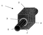
同様のプロセスで図4に示すモノブロックの形態のダイバータプレート1を製造した。
A
このため長さ10mm、直径15.2mmの孔を、30×20×10mmの大きさのタングステンブロック2の中央に貫通させた。外径15mm、壁厚d1mm、長さ10mmのリング3を、銅含有量20重量%のタングステンと銅との複合金属材料(T800と呼ぶ)からなるプレートから切り出した。
Therefore, a hole having a length of 10 mm and a diameter of 15.2 mm was passed through the center of the
厚み0.1mmのOHFC銅箔、T800から作ったリング3、および直径13mmで長さ15mmのOFHC銅の棒状物を、図2に示した材料の配列順に従って、タングステンブロックの貫通孔の中に装入した。次いでこの貫通させたタイルを、不活性ガス炉中に水素雰囲気下温度1250℃で30分間かけて、OFHC銅を用いてバックキャストした。バックキャストしたモノブロックを取り出してから、そのバックキャストした銅の中に、タングステンブロックの貫通孔と同心の直径12mmの貫通孔を穿孔した。この加工工程の後に、この複合ブロックは、貫通孔中に厚み0.50mmのOFHC銅層4を有する(図5参照)。このようにして製造した構造部材を、HIPプロセスで外径12mmとしたCu−Cr−Zr管5に接合した。この管に冷却構造7を、HIPユニットから取り出してから機械加工した。それに続けて超音波試験と金属組織学的分析をしたところ、このような方法で製造した複合体の接合部の品質が極めて良好であることが判った。
An OHFC copper foil having a thickness of 0.1 mm, a
1: 複合構造部材
2: プラズマ対向領域
3: 中間領域
4: 熱放散領域
5: 構造部材
6: 箔/シート
1: Composite structural member 2: Plasma facing region 3: Intermediate region 4: Heat dissipation region 5: Structural member 6: Foil / sheet
Claims (15)
前記中間部材(3)は、0.1mmより大かつ4mmより小の厚さを有し、銅と高融点金属との濃度分布が一様であって、銅成分が10〜40容積%、残部が高融点金属であることを特徴とする、核融合炉のための耐熱性の複合構造部材。 A composite structural member of heat resistance for the fusion reactor (1), the composite structural member (1) is at least, is a furnace wall member directly facing the fusion plasma tungsten or tungsten content 90 A plasma facing member (2) made of a tungsten alloy higher than% by weight, and a component adjacent to the plasma facing member for transferring the heat of plasma to the outside, having a thermal conductivity higher than 250 W / mK and an average crystal A heat dissipation member (4) made of copper or a copper alloy having a particle size larger than 100 μm, and between the plasma facing member (2) and the heat dissipation member (4), has a melting point exceeding 1800 ° C. becomes because the intermediate member (3) made of a composite metal with a high melting point metal and copper is at the IV b and group V b group element of the periodic table having,
Said intermediate member (3) has a large and small than 4mm thickness than 0.1 mm, the concentration distribution of copper and the refractory metal is a uniform, copper component is 10 to 40 volume%, the balance A heat-resistant composite structural member for a fusion reactor, characterized in that is a refractory metal .
Applications Claiming Priority (1)
| Application Number | Priority Date | Filing Date | Title |
|---|---|---|---|
| AT0022803U AT6636U1 (en) | 2003-04-02 | 2003-04-02 | COMPOSITE COMPONENT FOR FUSION REACTOR |
Publications (3)
| Publication Number | Publication Date |
|---|---|
| JP2004309485A JP2004309485A (en) | 2004-11-04 |
| JP2004309485A5 JP2004309485A5 (en) | 2007-05-17 |
| JP4540381B2 true JP4540381B2 (en) | 2010-09-08 |
Family
ID=29588067
Family Applications (1)
| Application Number | Title | Priority Date | Filing Date |
|---|---|---|---|
| JP2004110035A Expired - Fee Related JP4540381B2 (en) | 2003-04-02 | 2004-04-02 | Composite structural member for fusion reactor and method of manufacturing the same |
Country Status (9)
| Country | Link |
|---|---|
| US (1) | US7128980B2 (en) |
| EP (1) | EP1465205B1 (en) |
| JP (1) | JP4540381B2 (en) |
| KR (1) | KR101105065B1 (en) |
| CN (1) | CN100524540C (en) |
| AT (2) | AT6636U1 (en) |
| CA (1) | CA2462491C (en) |
| DE (1) | DE502004007529D1 (en) |
| PL (1) | PL1465205T3 (en) |
Families Citing this family (51)
| Publication number | Priority date | Publication date | Assignee | Title |
|---|---|---|---|---|
| AT8158U1 (en) * | 2004-10-27 | 2006-02-15 | Plansee Ag | MONOBLOCK COOLING COMPONENT |
| AT8485U1 (en) * | 2005-03-22 | 2006-08-15 | Plansee Se | FIRST WALL COMPONENT FOR FUSION REACTOR |
| AT8749U1 (en) * | 2005-08-29 | 2006-12-15 | Plansee Se | COMPOSITE COMPONENT WITH STRUCTURED TROPICAL HAMMOCK |
| AT9199U1 (en) * | 2005-09-13 | 2007-06-15 | Plansee Se | MATERIAL COMPOSITE WITH EXPLOSION-WELDED INTERMEDIATE PIECE |
| AT9173U1 (en) * | 2005-12-06 | 2007-05-15 | Plansee Se | FIRST WALL COMPONENT WITH RINGSEGMENT |
| AT9000U1 (en) * | 2005-12-23 | 2007-03-15 | Plansee Se | HEAT SINKS FROM A COPPER ALLOY |
| CN101626854B (en) * | 2007-01-29 | 2012-07-04 | 赢创德固赛有限责任公司 | Fumed metal oxides for investment casting |
| US20080206394A1 (en) * | 2007-02-27 | 2008-08-28 | Husky Injection Molding Systems Ltd. | Composite Nozzle Tip Method |
| DE102007016375A1 (en) | 2007-03-31 | 2008-10-02 | Deutsches Zentrum für Luft- und Raumfahrt e.V. | Components for heat sinks |
| US8268452B2 (en) * | 2007-07-31 | 2012-09-18 | Baker Hughes Incorporated | Bonding agents for improved sintering of earth-boring tools, methods of forming earth-boring tools and resulting structures |
| US20100046688A1 (en) * | 2008-08-25 | 2010-02-25 | Kotschenreuther Michael T | Magnetic confinement device |
| US20100063344A1 (en) * | 2008-09-11 | 2010-03-11 | Kotschenreuther Michael T | Fusion neutron source for fission applications |
| US8279994B2 (en) * | 2008-10-10 | 2012-10-02 | Board Of Regents, The University Of Texas System | Tokamak reactor for treating fertile material or waste nuclear by-products |
| US20100119025A1 (en) * | 2008-11-13 | 2010-05-13 | Kotschenreuther Michael T | Replaceable fusion neutron source |
| US20100246740A1 (en) * | 2009-03-26 | 2010-09-30 | Kotschenreuther Michael T | Nuclear Material Tracers |
| US20110114285A1 (en) * | 2009-11-17 | 2011-05-19 | Buxbaum Robert E | Copper-niobium, copper-vanadium, or copper-chromium nanocomposites, and the use thereof in heat exchangers |
| JP2011122883A (en) * | 2009-12-09 | 2011-06-23 | Kawasaki Heavy Ind Ltd | Method of manufacturing high-temperature load equipment by metallugically joining carbon material with copper-alloy material |
| US20110170649A1 (en) * | 2010-01-11 | 2011-07-14 | Kotschenreuther Michael T | Magnetic confinement device with aluminum or aluminum-alloy magnets |
| SE537113C2 (en) * | 2010-03-01 | 2015-01-20 | Westinghouse Electric Sweden | Fuel component and process for producing a fuel component |
| SE536815C2 (en) * | 2010-03-01 | 2014-09-16 | Westinghouse Electric Sweden | reactor Component |
| SE536814C2 (en) * | 2010-03-01 | 2014-09-16 | Westinghouse Electric Sweden | Neutron Absorbing Component and Process for Preparing a Neutron Absorbing Component |
| CN102312186B (en) * | 2010-07-02 | 2014-06-18 | 中国科学院上海硅酸盐研究所 | Method for improving bonding strength of vacuum plasma spraying tungsten coating |
| DE102010041532A1 (en) | 2010-09-28 | 2012-01-05 | Siemens Aktiengesellschaft | Composite component, has connector arranged between internal component and outer component, where inner component is connected with external component by thermal bonding process using connector |
| US9589678B2 (en) | 2011-04-01 | 2017-03-07 | The Boeing Company | Complex shape structure for liquid lithium first walls of fusion power reactor environments |
| US9511572B2 (en) | 2011-05-25 | 2016-12-06 | Southwest Research Institute | Nanocrystalline interlayer coating for increasing service life of thermal barrier coating on high temperature components |
| CN102284837B (en) * | 2011-07-07 | 2013-06-26 | 中国科学院等离子体物理研究所 | Manufacturing method of high-heating load part for nuclear fusion device |
| FR2978860A1 (en) * | 2011-08-01 | 2013-02-08 | Commissariat Energie Atomique | FIRST WALL COMPONENT FOR NUCLEAR FUSION REACTOR AND METHOD FOR PRODUCING THE SAME |
| DE102011115866A1 (en) * | 2011-10-13 | 2013-04-18 | Karlsruher Institut für Technologie | Metal pipe; Use of a metal tube as a structural component; Method for producing a metal pipe; metallic structural component; divertor |
| CN102610285A (en) * | 2012-03-16 | 2012-07-25 | 中国科学院等离子体物理研究所 | Structure utilizing metal tungsten as first wall material of magnetic confinement reactor |
| CN102626820B (en) * | 2012-04-17 | 2014-11-19 | 北京科技大学 | Method for vacuum hot-pressing welding of tungsten-diamond/copper-chromium zirconium copper |
| CN102677099A (en) * | 2012-06-12 | 2012-09-19 | 河北联合大学 | Ni-w gradient material and preparation method thereof |
| CN102922815B (en) * | 2012-07-26 | 2015-02-04 | 中国科学院等离子体物理研究所 | Water-cooled flat plate layered CuCrZr/OFHC-Cu/CVD-W plasma-facing part and manufacturing method thereof |
| CN102794612B (en) * | 2012-08-25 | 2015-01-21 | 安泰科技股份有限公司 | Preparation method of W/Cu composite component |
| CN103658904B (en) * | 2012-09-04 | 2016-01-20 | 核工业西南物理研究院 | A kind of tungsten copper composite block vacuum brazing Joining Technology |
| US9928926B2 (en) | 2013-04-03 | 2018-03-27 | Lockheed Martin Corporation | Active cooling of structures immersed in plasma |
| US10049773B2 (en) | 2013-04-03 | 2018-08-14 | Lockheed Martin Corporation | Heating plasma for fusion power using neutral beam injection |
| US9934876B2 (en) | 2013-04-03 | 2018-04-03 | Lockheed Martin Corporation | Magnetic field plasma confinement for compact fusion power |
| US9959942B2 (en) | 2013-04-03 | 2018-05-01 | Lockheed Martin Corporation | Encapsulating magnetic fields for plasma confinement |
| US9959941B2 (en) * | 2013-04-03 | 2018-05-01 | Lockheed Martin Corporation | System for supporting structures immersed in plasma |
| US9992917B2 (en) | 2014-03-10 | 2018-06-05 | Vulcan GMS | 3-D printing method for producing tungsten-based shielding parts |
| CN103886919B (en) | 2014-03-26 | 2016-02-17 | 北京工业大学 | Lamination is utilized to improve the method for fusion reactor inwall anti-plasma irradiation behaviour |
| RU2639320C1 (en) * | 2016-09-16 | 2017-12-21 | Российская Федерация, от имени которой выступает Государственная корпорация по атомной энергии "Росатом" | Device for electrical connecting intrachamber components with vacuum case of thermonuclear reactor |
| KR101938488B1 (en) | 2017-08-03 | 2019-01-14 | 서울대학교산학협력단 | Bi-continuous composite of refractory alloy and copper and manufacturing method for the same |
| CN108039209B (en) * | 2017-11-28 | 2020-08-25 | 中国科学院合肥物质科学研究院 | Divertor monolith type component with gradient adaptation layer for fusion reactor |
| CN109961856A (en) * | 2017-12-25 | 2019-07-02 | 哈尔滨工业大学 | It is a kind of to prevent from facing excessively high the first wall of nuclear fusion of plasma part temperature directly |
| CN111975005B (en) * | 2020-08-26 | 2022-08-30 | 合肥工业大学 | Tungsten-copper pipe penetrating component integrally formed by utilizing spark plasma sintering technology |
| CN113488202A (en) * | 2021-06-18 | 2021-10-08 | 中国科学院合肥物质科学研究院 | Water-cooling tungsten target module of rapid energy transfer fusion reactor divertor and cooling target plate structure |
| CN113523910A (en) * | 2021-06-22 | 2021-10-22 | 合肥聚能电物理高技术开发有限公司 | Hole groove machining method for tungsten-copper composite board and tungsten-copper composite board |
| CN113319418A (en) * | 2021-06-29 | 2021-08-31 | 哈尔滨工业大学 | Molybdenum-rhenium alloy interlayer-free diffusion bonding method |
| CN115090983B (en) * | 2022-07-26 | 2023-10-31 | 国电投核力创芯(无锡)科技有限公司 | Welding method for beam collecting barrel |
| CN116968397B (en) * | 2023-09-25 | 2023-12-15 | 上海核工程研究设计院股份有限公司 | Tritium permeation-preventing layered composite material and preparation method thereof |
Citations (2)
| Publication number | Priority date | Publication date | Assignee | Title |
|---|---|---|---|---|
| JPH01312015A (en) * | 1988-06-10 | 1989-12-15 | Toshiba Corp | Production of thermal expansion adjusting member |
| JPH05256968A (en) * | 1992-03-13 | 1993-10-08 | Hitachi Ltd | First wall of fusion reactor |
Family Cites Families (9)
| Publication number | Priority date | Publication date | Assignee | Title |
|---|---|---|---|---|
| JPS59151084A (en) * | 1983-02-18 | 1984-08-29 | 株式会社日立製作所 | Nuclear fusion device |
| US5126102A (en) * | 1990-03-15 | 1992-06-30 | Kabushiki Kaisha Toshiba | Fabricating method of composite material |
| US5126106A (en) | 1990-05-22 | 1992-06-30 | Tosoh Corporation | Chromium-based weld material and rolled article and process for producing the rolled article |
| JP3600350B2 (en) | 1996-03-07 | 2004-12-15 | 株式会社東芝 | Functionally graded material and method for producing the same |
| US6271585B1 (en) * | 1997-07-08 | 2001-08-07 | Tokyo Tungsten Co., Ltd. | Heat sink substrate consisting essentially of copper and molybdenum and method of manufacturing the same |
| US5988488A (en) * | 1997-09-02 | 1999-11-23 | Mcdonnell Douglas Corporation | Process of bonding copper and tungsten |
| US6089444A (en) * | 1997-09-02 | 2000-07-18 | Mcdonnell Douglas Corporation | Process of bonding copper and tungsten |
| JPH11190787A (en) | 1997-12-26 | 1999-07-13 | Japan Atom Energy Res Inst | Heat resistant direct joint structure of high melting point material and high thermal conductivity material or jointing method therefor |
| AT3175U1 (en) | 1999-02-05 | 1999-11-25 | Plansee Ag | METHOD FOR PRODUCING A THERMALLY HIGH-STRENGTH COMPOSITE COMPONENT |
-
2003
- 2003-04-02 AT AT0022803U patent/AT6636U1/en not_active IP Right Cessation
-
2004
- 2004-03-27 KR KR1020040020980A patent/KR101105065B1/en active IP Right Grant
- 2004-03-30 DE DE502004007529T patent/DE502004007529D1/en not_active Expired - Lifetime
- 2004-03-30 AT AT04007612T patent/ATE400876T1/en active
- 2004-03-30 CA CA2462491A patent/CA2462491C/en not_active Expired - Fee Related
- 2004-03-30 EP EP04007612A patent/EP1465205B1/en not_active Expired - Lifetime
- 2004-03-30 PL PL04007612T patent/PL1465205T3/en unknown
- 2004-03-30 US US10/814,311 patent/US7128980B2/en not_active Expired - Fee Related
- 2004-04-02 CN CNB2004100306653A patent/CN100524540C/en not_active Expired - Fee Related
- 2004-04-02 JP JP2004110035A patent/JP4540381B2/en not_active Expired - Fee Related
Patent Citations (2)
| Publication number | Priority date | Publication date | Assignee | Title |
|---|---|---|---|---|
| JPH01312015A (en) * | 1988-06-10 | 1989-12-15 | Toshiba Corp | Production of thermal expansion adjusting member |
| JPH05256968A (en) * | 1992-03-13 | 1993-10-08 | Hitachi Ltd | First wall of fusion reactor |
Also Published As
| Publication number | Publication date |
|---|---|
| CA2462491C (en) | 2012-01-03 |
| AT6636U1 (en) | 2004-01-26 |
| JP2004309485A (en) | 2004-11-04 |
| CN1538462A (en) | 2004-10-20 |
| PL1465205T3 (en) | 2008-11-28 |
| CN100524540C (en) | 2009-08-05 |
| KR101105065B1 (en) | 2012-01-13 |
| KR20040086198A (en) | 2004-10-08 |
| DE502004007529D1 (en) | 2008-08-21 |
| ATE400876T1 (en) | 2008-07-15 |
| CA2462491A1 (en) | 2004-10-02 |
| EP1465205A3 (en) | 2007-01-17 |
| EP1465205B1 (en) | 2008-07-09 |
| EP1465205A2 (en) | 2004-10-06 |
| US7128980B2 (en) | 2006-10-31 |
| US20040195296A1 (en) | 2004-10-07 |
Similar Documents
| Publication | Publication Date | Title |
|---|---|---|
| JP4540381B2 (en) | Composite structural member for fusion reactor and method of manufacturing the same | |
| US8249210B2 (en) | Monobloc cooling device component | |
| JP5450421B2 (en) | X-ray anode | |
| RU2403632C2 (en) | First wall component with pipe section | |
| CA2600187C (en) | First-wall component for a fusion reactor | |
| Barabash et al. | Armor and heat sink materials joining technologies development for ITER plasma facing components | |
| US20070243407A1 (en) | Machinable Metallic Composites | |
| JP5275555B2 (en) | Composite member with structured tungsten element | |
| CN108039209B (en) | Divertor monolith type component with gradient adaptation layer for fusion reactor | |
| JP4647746B2 (en) | Structural members that can be thermally loaded | |
| Vieider et al. | NET plasma facing components | |
| Cadden et al. | Aluminum-assisted joining of beryllium to copper for fusion applications | |
| JP2020101452A (en) | Dissimilar metal joint for diverter | |
| JPH05256968A (en) | First wall of fusion reactor | |
| Russell et al. | Friction stir welding of GRCop-84 for combustion chamber liners | |
| CN1032194C (en) | Process for making composite materials, and heat-receiving materials and making method therefor | |
| Gerken et al. | Development and Testing of Tungsten Emitters for Ion Propulsion Systems | |
| JPH02142683A (en) | Manufacture of thermal expansion adjustment material |
Legal Events
| Date | Code | Title | Description |
|---|---|---|---|
| A521 | Request for written amendment filed |
Free format text: JAPANESE INTERMEDIATE CODE: A523 Effective date: 20070327 |
|
| A621 | Written request for application examination |
Free format text: JAPANESE INTERMEDIATE CODE: A621 Effective date: 20070327 |
|
| A131 | Notification of reasons for refusal |
Free format text: JAPANESE INTERMEDIATE CODE: A131 Effective date: 20090623 |
|
| A521 | Request for written amendment filed |
Free format text: JAPANESE INTERMEDIATE CODE: A523 Effective date: 20090916 |
|
| A131 | Notification of reasons for refusal |
Free format text: JAPANESE INTERMEDIATE CODE: A131 Effective date: 20100420 |
|
| A521 | Request for written amendment filed |
Free format text: JAPANESE INTERMEDIATE CODE: A523 Effective date: 20100427 |
|
| TRDD | Decision of grant or rejection written | ||
| A01 | Written decision to grant a patent or to grant a registration (utility model) |
Free format text: JAPANESE INTERMEDIATE CODE: A01 Effective date: 20100525 |
|
| A01 | Written decision to grant a patent or to grant a registration (utility model) |
Free format text: JAPANESE INTERMEDIATE CODE: A01 |
|
| A61 | First payment of annual fees (during grant procedure) |
Free format text: JAPANESE INTERMEDIATE CODE: A61 Effective date: 20100622 |
|
| R150 | Certificate of patent or registration of utility model |
Free format text: JAPANESE INTERMEDIATE CODE: R150 |
|
| FPAY | Renewal fee payment (event date is renewal date of database) |
Free format text: PAYMENT UNTIL: 20130702 Year of fee payment: 3 |
|
| R250 | Receipt of annual fees |
Free format text: JAPANESE INTERMEDIATE CODE: R250 |
|
| R250 | Receipt of annual fees |
Free format text: JAPANESE INTERMEDIATE CODE: R250 |
|
| R250 | Receipt of annual fees |
Free format text: JAPANESE INTERMEDIATE CODE: R250 |
|
| R250 | Receipt of annual fees |
Free format text: JAPANESE INTERMEDIATE CODE: R250 |
|
| LAPS | Cancellation because of no payment of annual fees |