JP4539799B2 - Thermoplastic material molding equipment - Google Patents
Thermoplastic material molding equipment Download PDFInfo
- Publication number
- JP4539799B2 JP4539799B2 JP2001052447A JP2001052447A JP4539799B2 JP 4539799 B2 JP4539799 B2 JP 4539799B2 JP 2001052447 A JP2001052447 A JP 2001052447A JP 2001052447 A JP2001052447 A JP 2001052447A JP 4539799 B2 JP4539799 B2 JP 4539799B2
- Authority
- JP
- Japan
- Prior art keywords
- suction
- shaped member
- compression bell
- clamping frame
- seal
- Prior art date
- Legal status (The legal status is an assumption and is not a legal conclusion. Google has not performed a legal analysis and makes no representation as to the accuracy of the status listed.)
- Expired - Fee Related
Links
Images


Classifications
-
- B—PERFORMING OPERATIONS; TRANSPORTING
- B29—WORKING OF PLASTICS; WORKING OF SUBSTANCES IN A PLASTIC STATE IN GENERAL
- B29C—SHAPING OR JOINING OF PLASTICS; SHAPING OF MATERIAL IN A PLASTIC STATE, NOT OTHERWISE PROVIDED FOR; AFTER-TREATMENT OF THE SHAPED PRODUCTS, e.g. REPAIRING
- B29C51/00—Shaping by thermoforming, i.e. shaping sheets or sheet like preforms after heating, e.g. shaping sheets in matched moulds or by deep-drawing; Apparatus therefor
- B29C51/26—Component parts, details or accessories; Auxiliary operations
- B29C51/261—Handling means, e.g. transfer means, feeding means
- B29C51/262—Clamping means for the sheets, e.g. clamping frames
-
- B—PERFORMING OPERATIONS; TRANSPORTING
- B29—WORKING OF PLASTICS; WORKING OF SUBSTANCES IN A PLASTIC STATE IN GENERAL
- B29C—SHAPING OR JOINING OF PLASTICS; SHAPING OF MATERIAL IN A PLASTIC STATE, NOT OTHERWISE PROVIDED FOR; AFTER-TREATMENT OF THE SHAPED PRODUCTS, e.g. REPAIRING
- B29C51/00—Shaping by thermoforming, i.e. shaping sheets or sheet like preforms after heating, e.g. shaping sheets in matched moulds or by deep-drawing; Apparatus therefor
- B29C51/26—Component parts, details or accessories; Auxiliary operations
- B29C51/30—Moulds
- B29C51/38—Opening, closing or clamping means
-
- B—PERFORMING OPERATIONS; TRANSPORTING
- B29—WORKING OF PLASTICS; WORKING OF SUBSTANCES IN A PLASTIC STATE IN GENERAL
- B29C—SHAPING OR JOINING OF PLASTICS; SHAPING OF MATERIAL IN A PLASTIC STATE, NOT OTHERWISE PROVIDED FOR; AFTER-TREATMENT OF THE SHAPED PRODUCTS, e.g. REPAIRING
- B29C2791/00—Shaping characteristics in general
- B29C2791/004—Shaping under special conditions
- B29C2791/007—Using fluid under pressure
-
- B—PERFORMING OPERATIONS; TRANSPORTING
- B29—WORKING OF PLASTICS; WORKING OF SUBSTANCES IN A PLASTIC STATE IN GENERAL
- B29C—SHAPING OR JOINING OF PLASTICS; SHAPING OF MATERIAL IN A PLASTIC STATE, NOT OTHERWISE PROVIDED FOR; AFTER-TREATMENT OF THE SHAPED PRODUCTS, e.g. REPAIRING
- B29C51/00—Shaping by thermoforming, i.e. shaping sheets or sheet like preforms after heating, e.g. shaping sheets in matched moulds or by deep-drawing; Apparatus therefor
- B29C51/04—Combined thermoforming and prestretching, e.g. biaxial stretching
- B29C51/06—Combined thermoforming and prestretching, e.g. biaxial stretching using pressure difference for prestretching
-
- B—PERFORMING OPERATIONS; TRANSPORTING
- B29—WORKING OF PLASTICS; WORKING OF SUBSTANCES IN A PLASTIC STATE IN GENERAL
- B29C—SHAPING OR JOINING OF PLASTICS; SHAPING OF MATERIAL IN A PLASTIC STATE, NOT OTHERWISE PROVIDED FOR; AFTER-TREATMENT OF THE SHAPED PRODUCTS, e.g. REPAIRING
- B29C51/00—Shaping by thermoforming, i.e. shaping sheets or sheet like preforms after heating, e.g. shaping sheets in matched moulds or by deep-drawing; Apparatus therefor
- B29C51/08—Deep drawing or matched-mould forming, i.e. using mechanical means only
-
- B—PERFORMING OPERATIONS; TRANSPORTING
- B29—WORKING OF PLASTICS; WORKING OF SUBSTANCES IN A PLASTIC STATE IN GENERAL
- B29L—INDEXING SCHEME ASSOCIATED WITH SUBCLASS B29C, RELATING TO PARTICULAR ARTICLES
- B29L2031/00—Other particular articles
- B29L2031/762—Household appliances
- B29L2031/7622—Refrigerators
-
- Y—GENERAL TAGGING OF NEW TECHNOLOGICAL DEVELOPMENTS; GENERAL TAGGING OF CROSS-SECTIONAL TECHNOLOGIES SPANNING OVER SEVERAL SECTIONS OF THE IPC; TECHNICAL SUBJECTS COVERED BY FORMER USPC CROSS-REFERENCE ART COLLECTIONS [XRACs] AND DIGESTS
- Y10—TECHNICAL SUBJECTS COVERED BY FORMER USPC
- Y10S—TECHNICAL SUBJECTS COVERED BY FORMER USPC CROSS-REFERENCE ART COLLECTIONS [XRACs] AND DIGESTS
- Y10S425/00—Plastic article or earthenware shaping or treating: apparatus
- Y10S425/809—Seal, bottle caps only
Landscapes
- Engineering & Computer Science (AREA)
- Mechanical Engineering (AREA)
- Blow-Moulding Or Thermoforming Of Plastics Or The Like (AREA)
- Casting Or Compression Moulding Of Plastics Or The Like (AREA)
- Moulds For Moulding Plastics Or The Like (AREA)
Description
【0001】
【発明の属する技術分野】
本発明は、吸引兼圧縮鐘形部材と、上側の締付けフレームと、下側の締付けフレームと、成形型を有する下側部分とを備え、この両締付けフレームの間に、成形すべき材料を挟むことができる、熱可塑性材料を成形するための装置に関する。
【0002】
【従来の技術】
この種の公知の装置の場合には、フィルム材料を成形型に押し付けるために、圧縮鐘形部材に圧縮空気を供給する成形過程のために、圧縮鐘形部材と、成形型を支持する下側部分が液圧操作式駆動装置によって互いに押し付けられる。それによって、大きな成形品を製作するときの大きな力を受け止めることができる。
この力は、互いに押し付けられる部品、すなわち圧縮鐘形部材と下側部分を、その間にある締付けフレームと共に、互いに分離しようとする。その際、例えば冷蔵庫インサートの場合のような大きな部品の場合には、例えば800kN以上の非常に大きな力が発生する。この場合に発生する重要な問題は、圧縮鐘形部材とその下側部分を押し付けるために非常に大きな保持力が必要であることだけでなく、長さと幅がほぼ圧縮鐘形部材に適合している締付け付けフレームを使用しなければならないことにある。これに対して、小さな部品を製作するために小さな成形型を使用するときには、他の締付けフレーム、すなわち非常に小さな貫通穴を有する締付けフレームを使用しなければならない。上側の締付けフレームを圧縮鐘形部材に封止的に接触させなければならないので、この締付けフレームは、製作すべき大きな部品のための圧縮鐘形部材から出発して、製作すべき小さな部品に移行するときに、比較的に大きな面を有する。圧縮鐘形部材内の圧力がこの大きな面に作用する。締付けフレームの面は、小さな型のために小さな通過穴を有し、シールのために圧縮鐘形部材のエッジまで達するような大きさである。上側の締付けフレームのこの大きな面には、圧縮鐘形部材内に加えられる圧力が作用する。これは締付けフレームを変形することになる。なぜなら、下側部分から下側の締付けフレームを介して上側の締付けフレームに伝達される締付け力が、小さな穴を有する締付けフレームの場合、大きな穴を有する締付けフレームの場合よりも大きなてこ長さで作用するからである。その際、比較的に大きな力が、圧縮鐘形部材と上側の締付けフレームとの間に設けられたシールに伝達される。
このシールはゴムシールリングとして形成され、従って例えば上側の締付けフレームの厚さ寸法の誤差と、成形すべき材料の異なる厚さを補償するために任意に変形不可能である。この大きな欠点を回避するために、圧縮鐘形部材と下側部分を組み合わせる際にストッパーを使用することが既に知られている。このストッパーは上側の締付けフレームとシールに作用するきわめて大きな力を制限する。
この場合、装置全体が、上側の締付けフレームフランジに発生する誤差と、成形すべき材料の厚さに影響を受けやすい。
【0003】
【発明が解決しようとする課題】
本発明の課題は、吸引兼圧縮鐘形部材と下側部分を突き合わせる際に、シールが押しつぶされないかあるいは損傷せず、シール作用が吸引兼圧縮鐘形部材内の内圧に適合可能であり、そして上側の締付けフレームのフランジと成形すべき材料の厚さ誤差が広い範囲で補償可能であるように、冒頭に述べた種類の装置を形成することである。
【0004】
【課題を解決するための手段】
この課題は上述の種類の装置において本発明に従い、吸引兼圧縮鐘形部材と上側の締付けフレームとの間に、調節可能な力の作用を受けて膨張可能であるシールが設けられていることによって解決される。
【0005】
この実施形は、上側の締付けフレームがシールを予備付勢することによって成形位置に保持可能であるという利点がある。シールが調節可能な力の作用によって任意に膨張可能であるので、シールはそのシール作用を、吸引兼圧縮鐘形部材の内室のその都度の圧力に適合させることができる。シールが力の作用を受けて任意に膨張可能であるので、上側の締付けフレームのフランジの厚さ寸法誤差と、成形すべき材料の圧力の変化を簡単に補償可能である。
【0006】
本発明によるこの実施形の利点は、上述の種類の装置と関連して、本発明の他の実施形において、吸引兼圧縮鐘形部材と、成形型を支持する下側部分が、力受け止め装置によって互いに連結可能であり、この力受け止め装置が成形時に発生する力を完全に受け止めるときに、きわめて顕著である。
【0007】
この力受け止め装置により、吸引兼圧縮鐘形部材と付設の下側部分とその間に配置された締付けフレームが互いに保持され、技術水準の場合のように互いに押し合わない。すなわち、圧縮成形時に発生する大きな力が力受け止め装置によって受け止められるので、特に締付けフレームに対して、両部品を互いに押し付け合う場合よりも非常に小さな力しか作用しない。なぜなら、吸引兼圧縮鐘形部材と下側部分を互いに押し付け合う場合には、この押し付け力が締付けフレームを介して伝達されるからである。これに対して、本発明に従って、吸引兼圧縮鐘形部材と下側部分が、外側に取付けられた力受け止め装置によって互いに保持されると、吸引兼圧縮鐘形部材と下側部分の間に配置されたフレームが、非常に大きな力から充分に解放された状態にある。なぜなら、約4バールの圧力と、分離範囲内の吸引兼圧縮鐘形部材の面とによって生じる力が、締付けフレームと成形型ひいては下側部分に作用しないで、成形型を介して下側部分に作用し、この下側部分において外部に配置されたロック装置によって受け止められるからである。
それによって、力の伝達、特に締付けフレームを経て行われる力の伝達が充分に低減される。勿論、締付けフレームが分離範囲内の吸引兼圧縮鐘形部材の面よりもはるかに小さな穴を有するときには、締付けフレームに力が作用するがしかし、この力は締付けフレームを適当に形成することによって受け止め可能である。
なぜなら、この力が、技術水準の場合のように、全部の力を締付けフレームを経て下側部分に伝達する場合よりもはるかに小さいからである。
【0008】
用語“吸引兼圧縮鐘形部材”は、圧縮成形の前にフィルムまたは板が吸引作用によって吸引兼圧縮鐘形部材内に引き込まれ、それによって予備成形されることを意味する。
【0009】
ロック装置として形成された力受け止め装置は好ましくは、吸引兼圧縮鐘形部材の外周に固定配置された複数の錠止棒を備え、この錠止棒が吸引兼鐘形部材と下側部分の組み合わせ状態で、下側部分に設けた連結装置によって固定可能である。この連結装置は錠止棒の端部を掴んで固定保持する急速締付け装置として形成可能である。錠止棒を適当に採寸し、その必要な数を適当に選択することにより、非常に大きな力がこの錠止棒とその連結装置によって受け止め可能である。
この場合、連結装置は錠止棒の端部に形状補完的に作用するので、互いに係合する部品、すなわち錠止棒の端部と連結装置の部分を互いに保持するために、大きな締付け力を加える必要がない。
【0010】
膨張可能なシールの配置に関する、本発明による実施形の利点は、吸引兼圧縮鐘形部材と下側部分がそれぞれの駆動装置によって互いに押し付け可能であり、特に相互の押し付け力がストッパーによって制限されるときに押し付け可能であることによっても得られる。
【0011】
従来は外部の押圧力によって強く圧縮された、吸引兼圧縮鐘形部材と上側の締付けフレームとの間のシールは、ロック装置により、大きな力を受けることがない。本発明の他の実施形では、シールが吸引兼圧縮鐘形部材の溝に収容され、吸引兼圧縮鐘形部材と締付けフレームの間をシールするために圧力媒体によって上側の締付けレームに押し付け可能である。本発明による実施形の場合には、シールは互いに向き合った外部の押圧力を受けず、吸引兼圧縮鐘形部材内の正圧の低下を防止するためにシールする必要があるような強さによってのみ、圧力媒体によって付勢される。
【0012】
他の有利な実施形では、シールが膨らまし可能なホースシールとして形成されている。この膨張可能なシールは吸引兼圧縮鐘形部材内の内圧または吸引兼圧縮鐘形部材と上側の締付けフレームの間の隙間内の内圧にのみ耐えればよく、公知の装置の場合のような押圧力を受けない。
【0013】
特に雄型の場合に離型を可能にするために、吸引兼圧縮鐘形部材は好ましくは、駆動装置によって高さ方向に摺動可能である。
【0014】
本発明の他の実施形では、下側部分が成形型と締付けフレームと共に、駆動装置によって吸引兼圧縮鐘形部材の方に移動可能である。下側部分と成形型は負圧源に接続可能である。
【0015】
上側の締付けフレームを容易に取扱い操作するために、上側の締付けフレームは液圧または空気圧で操作可能な作動シリンダによって吸引兼圧縮鐘形部材上に位置保持可能である。
【0016】
【発明の実施の形態】
次に、実施の形態に基づいて本発明を詳しく説明する。
【0017】
熱可塑性材料を成形(変形)するための装置、すなわち成形体、例えば冷蔵庫内側パネルを製作するための装置は、上側に位置する吸引兼圧縮鐘形部材(吸引兼圧縮ベル)1と、下側部分2と、3で示したロック装置を備えている。このロック装置は錠止棒4を備え、この錠止棒は吸引兼圧縮鐘形部材に固定連結されたホルダー5に挿入されている。錠止棒4はその下端に、連結装置7と協働する特に適合した端部材6を備えている。この連結装置は下側部分に固定されている。
それによって、急速ロック装置が形成される。このロック装置によって、吸引兼圧縮鐘形部材1と下側部分2を図2の突き合わせ状態に保持し、しかも吸引兼圧縮鐘形部材内の圧力の大きさと、それによって生じる、下側部分から吸引兼圧縮鐘形部材を分離しようとする力の大きさに関係なく保持する。吸引兼圧縮鐘形部材1と下側部分2は垂直方向に移動可能である。
【0018】
下側部分2上には成形型8と下側の締付けフレーム9が設けられている。対応する上側の締付けフレーム10は作動シリンダ11によって、上側部分、すなわち吸引兼圧縮鐘形部材1に保持されている。この作動シリンダはスライダ12によって上側の締付けフレームに作用する。熱可塑性樹脂からなる変形すべきフィルムまたは板は13で示してあり、両締付けフレーム9,10の間の範囲内で、両側に設けられた搬送チェーン14によって引っ張られている。上側締付けフレーム10と吸引兼圧縮鐘形部材1との間のシールはシール15によって行われる。このシールは吸引兼圧縮鐘形部材1の開放側の外周エッジに設けられ、開放した締付けフレーム10のフランジ16によって押圧可能である。そのために、シールは圧力媒体によって付勢可能であるので、シールは上側の締付けフレームと吸引兼圧縮鐘形部材の間をシールするためだけでなく、上側の締付けフレーム10またはフィルム13の誤差を補償するためにも役立つ。成形部材を製造するために、前もって加熱されたフィルム13が搬送チェーン14によって、締付けフレーム9,10の間の範囲内に挿入される。そして、吸引兼圧縮鐘形部材1と下側部分2が図2に示す位置まで近接して突き合わせられ、そこで互いに錠止させられる。下側の締付けフレーム9は付加的な駆動装置によってフィルム13に押し付け可能である。続いて、予備吸引過程が開始される。この予備吸引過程では、フィルムが吸引兼圧縮鐘形部材内に引き込まれる。予備吸引過程の後で、圧縮空気が吸引兼圧縮鐘形部材内に供給されるので、予備成形されたフィルムまたは板は成形型8に押し付けられる。それによって、成形体の内面は成形型8の形状に正確に一致する。本来の成形過程はここでは詳しく説明しない。なぜなら、これは本発明の対象ではないからである。
【0019】
図3,4には変形が示してある。この変形は本発明による実施形の利点を明瞭に示している。この変形は、他の締付けフレームが使用される点にある。この他の締付けフレームはその通過面積がはるかに小さな成形型17のために設けられている。締付けフレームはここでは18,19によって示してある。図3,4から明らかなように、20で示した、成形型17用の通過面積は、図1,2の実施の形態の場合よりもはるかに小さい。これによって、シール15と穴20の間に、比較的に大きな面21が生じる。この面には、吸引兼圧縮鐘形部材内での成形のために必要な圧力が作用するがしかし、締付けフレーム19は、吸引兼圧縮鐘形部材19と下側部分を互いに押し付けるときに技術水準で締付けフレーム19に伝達される力を受けていない。この力が生じないので、締付けフレーム19は、全面に作用する圧力、すなわちシール15と開口20の間の面に作用する圧力を受け止めることができるように安定するように形成するだけでよい。この負荷はそれほど大きくはない。なぜなら、上側の締付けフレーム19がその穴エッジで下側の締付けフレーム18に支持されるからである。この圧力は技術水準の場合よりもはるかに小さい。技術水準の場合には、締付けフレームを介して、吸引兼圧縮鐘形部材と下側部分を互いに押し付けるための全部の力が作用する。
【0020】
吸引兼圧縮鐘形部材1を仕上げ過程のための製作ライン内の位置に移動させ、続いて離型位置に移動させるために必要な駆動装置は図示していない。更に、成形型17と締付けフレーム9または18と共に下側部分2を、図2,4に示すように、ロック位置まで上方に移動させる駆動装置は図示していない。
【図面の簡単な説明】
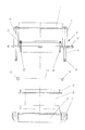
【図1】大きな締付けフレームを備えた、熱可塑性材料を圧縮空気成形するための装置の開放状態を示す図である。
【図2】図1の装置の突き当て状態を示す図である。
【図3】非常に小さな締付けフレームを備えた図1の装置の開放状態を示す図である。
【図4】図3の装置の突き当て状態を示す図である。
【符号の説明】
1 吸引兼圧縮鐘形部材
2 下側部分
3 力受け止め装置
4 錠止棒
7 連結装置
8,17 成形型
9,18 締付けフレーム
10,19 締付けフレーム
11 作動シリンダ
12 スライダ
15 シール[0001]
BACKGROUND OF THE INVENTION
The present invention comprises a suction and compression bell-shaped member, an upper clamping frame, a lower clamping frame, and a lower part having a molding die, and a material to be molded is sandwiched between the clamping frames. The invention relates to an apparatus for molding a thermoplastic material.
[0002]
[Prior art]
In the case of a known device of this kind, a compression bell and a lower side supporting the mold for the molding process of supplying compressed air to the compression bell to press the film material against the mold. The parts are pressed together by a hydraulically operated drive. Thereby, it is possible to receive a large force when manufacturing a large molded product.
This force tends to separate the parts that are pressed together, ie the compression bell and the lower part, together with the clamping frame between them. In that case, in the case of a large part, for example in the case of a refrigerator insert, a very large force of, for example, 800 kN or more is generated. The important problem that arises in this case is not only that a very large holding force is required to press the compression bell and its lower part, but also that the length and width are approximately compatible with the compression bell. The tightening frame must be used. In contrast, when using a small mold to produce a small part, another clamping frame, i.e. a clamping frame with very small through holes, must be used. Since the upper clamping frame has to be in sealing contact with the compression bell, this clamping frame starts from the compression bell for the large part to be manufactured and transitions to the small part to be manufactured. When having a relatively large surface. The pressure in the compression bell member acts on this large surface. The face of the clamping frame has a small passage hole for a small mold and is sized to reach the edge of the compression bell for sealing. This large surface of the upper clamping frame is subjected to pressure applied in the compression bell. This will deform the clamping frame. This is because the tightening force transmitted from the lower part to the upper tightening frame via the lower tightening frame is larger in the case of a tightening frame having a small hole than in the case of a tightening frame having a large hole. Because it works. In this case, a relatively large force is transmitted to a seal provided between the compression bell-shaped member and the upper clamping frame.
This seal is formed as a rubber seal ring and is therefore not arbitrarily deformable, for example to compensate for errors in the thickness dimensions of the upper clamping frame and the different thicknesses of the material to be molded. In order to avoid this major drawback, it is already known to use a stopper when combining the compression bell and the lower part. This stopper limits the very large forces acting on the upper clamping frame and seal.
In this case, the entire device is susceptible to errors occurring in the upper clamping frame flange and the thickness of the material to be molded.
[0003]
[Problems to be solved by the invention]
The problem of the present invention is that when the suction / compression bell-shaped member and the lower part are brought into contact with each other, the seal is not crushed or damaged, and the sealing action can be adapted to the internal pressure in the suction / compression bell-shaped member. And to form a device of the kind mentioned at the beginning so that the thickness error of the upper clamping frame flange and the material to be molded can be compensated in a wide range.
[0004]
[Means for Solving the Problems]
This object is achieved in accordance with the invention in a device of the kind described above by the provision of a seal that is inflatable under the action of an adjustable force between the suction and compression bell-shaped member and the upper clamping frame. Solved.
[0005]
This embodiment has the advantage that the upper clamping frame can be held in the molding position by pre-biasing the seal. Since the seal is optionally expandable by the action of an adjustable force, the seal can adapt its sealing action to the respective pressure in the inner chamber of the suction and compression bell. Since the seal is arbitrarily expandable under the action of a force, it is possible to easily compensate for the thickness dimensional error of the upper clamping frame flange and the pressure change of the material to be molded.
[0006]
The advantage of this embodiment according to the present invention is that, in connection with an apparatus of the type described above, in another embodiment of the present invention, the suction and compression bell-shaped member and the lower part supporting the mold are a force receiving device. Can be connected to each other, and this is particularly noticeable when this force-receiving device completely receives the forces generated during molding.
[0007]
With this force catching device, the suction and compression bell-shaped member, the attached lower part and the clamping frame arranged between them are held together and do not press against each other as in the state of the art. That is, since a large force generated at the time of compression molding is received by the force receiving device, only a much smaller force is applied to the fastening frame than when both parts are pressed against each other. This is because when the suction / compression bell-shaped member and the lower part are pressed against each other, this pressing force is transmitted through the tightening frame. On the other hand, according to the present invention, when the suction and compression bell-shaped member and the lower portion are held together by the force receiving device attached to the outside, the suction and compression bell-shaped member is disposed between the suction and compression bell-shaped member and the lower portion. The frame that has been made is sufficiently released from a very large force. This is because the force generated by the pressure of about 4 bar and the surface of the suction and compression bell-shaped member in the separation range does not act on the clamping frame and the mold and thus on the lower part, but on the lower part via the mold. This is because it acts and is received by a locking device arranged outside in this lower part.
Thereby, the transmission of force, in particular the transmission of force that takes place via the clamping frame, is sufficiently reduced. Of course, when the clamping frame has a much smaller hole than the face of the suction and compression bell-shaped member within the separation range, a force acts on the clamping frame, but this force is received by appropriately forming the clamping frame. Is possible.
This is because this force is much smaller than when the entire force is transmitted to the lower part via the clamping frame, as in the state of the art.
[0008]
The term “suction and compression bell” means that before compression molding, the film or plate is drawn into the suction and compression bell by suction to thereby be preformed.
[0009]
The force receiving device formed as a locking device preferably comprises a plurality of locking rods fixedly arranged on the outer periphery of the suction and compression bell-shaped member, the locking rod being a combination of the suction and bell-shaped member and the lower part In the state, it can be fixed by a connecting device provided in the lower part. This connecting device can be formed as a quick fastening device that holds and holds the end of the locking bar. By appropriately measuring the locking bars and selecting the required number, a very large force can be received by this locking bar and its connecting device.
In this case, since the coupling device acts in a complementary manner on the end of the locking rod, a large tightening force is required to hold the parts that are engaged with each other, that is, the end of the locking rod and the portion of the coupling device. There is no need to add.
[0010]
The advantage of the embodiment according to the invention regarding the arrangement of the inflatable seal is that the suction and compression bell and the lower part can be pressed against each other by the respective drive, in particular the mutual pressing force is limited by the stopper. Sometimes it can also be obtained by being able to press.
[0011]
The seal between the suction-and-compression bell-shaped member and the upper fastening frame, which has been strongly compressed by an external pressing force in the past, does not receive a large force due to the locking device. In another embodiment of the present invention, the seal is received in the groove of the suction and compression bell member and can be pressed against the upper clamping frame by a pressure medium to seal between the suction and compression bell member and the clamping frame. is there. In the case of the embodiment according to the invention, the seal is not subject to external pressing forces facing each other, but with such strength that it needs to be sealed to prevent a decrease in the positive pressure in the suction and compression bell-shaped member. Only energized by the pressure medium.
[0012]
In another advantageous embodiment, the seal is formed as an inflatable hose seal. This inflatable seal need only withstand the internal pressure in the suction / compression bell-shaped member or the internal pressure in the gap between the suction / compression bell-shaped member and the upper clamping frame. Not receive.
[0013]
The suction and compression bell-shaped member is preferably slidable in the height direction by a drive device, in particular in order to allow release in the case of a male mold.
[0014]
In another embodiment of the invention, the lower part, together with the mold and the clamping frame, can be moved towards the suction and compression bell by the drive. The lower part and the mold can be connected to a negative pressure source.
[0015]
In order to easily handle and operate the upper clamping frame, the upper clamping frame can be held in position on the suction and compression bell-shaped member by an actuating cylinder which can be operated hydraulically or pneumatically.
[0016]
DETAILED DESCRIPTION OF THE INVENTION
Next, the present invention will be described in detail based on embodiments.
[0017]
An apparatus for molding (deforming) a thermoplastic material, that is, an apparatus for producing a molded body, for example, a refrigerator inner panel, includes a suction and compression bell-shaped member (suction and compression bell) 1 positioned on the upper side, and a lower side. The locking device indicated by
Thereby, a quick locking device is formed. With this locking device, the suction / compression bell-shaped
[0018]
A molding die 8 and a lower fastening frame 9 are provided on the
[0019]
A modification is shown in FIGS. This variant clearly shows the advantages of the embodiment according to the invention. This variant is in that other clamping frames are used. This other clamping frame is provided for a
[0020]
The drive required to move the suction and compression bell-shaped
[Brief description of the drawings]
1 shows an open state of an apparatus for compressed air molding of a thermoplastic material with a large clamping frame.
FIG. 2 is a view showing a butting state of the apparatus of FIG. 1;
3 shows the open state of the device of FIG. 1 with a very small clamping frame.
4 is a view showing a butting state of the apparatus of FIG. 3; FIG.
[Explanation of symbols]
DESCRIPTION OF
Claims (9)
Applications Claiming Priority (2)
| Application Number | Priority Date | Filing Date | Title |
|---|---|---|---|
| DE10009405A DE10009405A1 (en) | 2000-02-28 | 2000-02-28 | Molding machine for thermoplastics comprises suction-pressure chamber, frames between which material to be molded can be retained and lower molding section, expandable seal being fitted between chamber and upper clamping frame |
| DE10009405:8 | 2000-02-28 |
Publications (3)
| Publication Number | Publication Date |
|---|---|
| JP2001246665A JP2001246665A (en) | 2001-09-11 |
| JP2001246665A5 JP2001246665A5 (en) | 2008-01-31 |
| JP4539799B2 true JP4539799B2 (en) | 2010-09-08 |
Family
ID=7632743
Family Applications (1)
| Application Number | Title | Priority Date | Filing Date |
|---|---|---|---|
| JP2001052447A Expired - Fee Related JP4539799B2 (en) | 2000-02-28 | 2001-02-27 | Thermoplastic material molding equipment |
Country Status (4)
| Country | Link |
|---|---|
| US (1) | US6589041B2 (en) |
| EP (1) | EP1127676B1 (en) |
| JP (1) | JP4539799B2 (en) |
| DE (2) | DE10009405A1 (en) |
Families Citing this family (14)
| Publication number | Priority date | Publication date | Assignee | Title |
|---|---|---|---|---|
| AU2004100000A4 (en) | 2004-01-02 | 2004-02-12 | Sands Innovations Pty Ltd | Dispensing stirring implement |
| CN101479201A (en) * | 2006-07-06 | 2009-07-08 | 旭硝子株式会社 | Apparatus for molding optical element and method for molding optical element |
| DE102006032862A1 (en) * | 2006-07-14 | 2008-01-17 | Geiss Ag | Thermoforming machine |
| US7429168B2 (en) * | 2006-09-01 | 2008-09-30 | Petersen Albert O | Oven protection system for a thermo-forming machine |
| BRPI0806943A2 (en) | 2007-01-31 | 2014-05-06 | Sands Innovations Pty Ltd | DISPENSING UTENSIL AND MANUFACTURING METHOD |
| EP2373551B1 (en) | 2008-12-09 | 2015-04-08 | Sands Innovations Pty Ltd. | A dispensing container |
| USD636890S1 (en) | 2009-09-17 | 2011-04-26 | Sands Innovations Pty. Ltd. | Dispensing utensil |
| US8511500B2 (en) | 2010-06-07 | 2013-08-20 | Sands Innovations Pty. Ltd. | Dispensing container |
| US8485360B2 (en) | 2011-03-04 | 2013-07-16 | Sands Innovations Pty, Ltd. | Fracturable container |
| ITBO20130700A1 (en) * | 2013-12-20 | 2015-06-21 | Comi S P A | PLASTIC MATERIAL THERMOFORMING DEVICE |
| ITUA20162593A1 (en) | 2016-04-15 | 2016-07-15 | Persico Spa | System and procedure for making a molded article in expanded material |
| TWI673158B (en) * | 2018-08-28 | 2019-10-01 | 邁雅設計有限公司 | Vacuum plastic board equipment |
| US11685103B2 (en) * | 2021-04-23 | 2023-06-27 | Mayku Ltd | Pressure forming machine |
| USD990532S1 (en) | 2021-04-23 | 2023-06-27 | Mayku Ltd | Pressure forming machine |
Citations (6)
| Publication number | Priority date | Publication date | Assignee | Title |
|---|---|---|---|---|
| JPS5394960U (en) * | 1976-12-30 | 1978-08-02 | ||
| JPS5490257A (en) * | 1978-04-26 | 1979-07-17 | Nissha Printing | Apparatus for embossing thermoplastic resin sheet |
| GB2101927A (en) * | 1981-07-03 | 1983-01-26 | Illig Maschinenbau Adolf | Moulding apparatus |
| JPS6364721A (en) * | 1986-09-08 | 1988-03-23 | T V G:Kk | Pressure forming |
| JPH04247926A (en) * | 1991-01-25 | 1992-09-03 | Araco Corp | Thermoforming device of plastic |
| JP2001138391A (en) * | 1999-11-11 | 2001-05-22 | Asano Laboratories Co Ltd | Method and apparatus for molding resin molded product |
Family Cites Families (10)
| Publication number | Priority date | Publication date | Assignee | Title |
|---|---|---|---|---|
| US3726953A (en) * | 1968-05-29 | 1973-04-10 | Mc Donnell Douglas Corp | Method of forming sheet material |
| US3753830A (en) * | 1970-07-13 | 1973-08-21 | United States Steel Corp | Apparatus for laminating a plastic sheet onto a surface of a hollow body |
| GB1466531A (en) * | 1974-01-15 | 1977-03-09 | Sanson Joseph | Manufacture of cushions |
| DE3620954A1 (en) * | 1986-06-23 | 1988-05-26 | Benecke Gmbh J | TENSION FRAME FOR SOLVABLE CLAMPING OF A FILM |
| US4842742A (en) * | 1986-08-25 | 1989-06-27 | Whirlpool Corporation | Method for forming large objects such as refrigerator liners from crystalline synthetic resins |
| DE3643078C1 (en) * | 1986-12-17 | 1988-03-10 | Metzeler Schaum Gmbh | Process and mould for producing cushions with foam-backed coverings |
| US5074773A (en) * | 1990-04-12 | 1991-12-24 | Davidson Textron Inc. | Adjustable gasket alignment block |
| US5759591A (en) * | 1996-06-28 | 1998-06-02 | Maytag Corporation | Apparatus for thermoforming a plastic appliance door |
| DE29617441U1 (en) * | 1996-10-08 | 1998-02-05 | Illig Maschinenbau Adolf | Forming station |
| US6315295B1 (en) * | 1997-03-04 | 2001-11-13 | Magna International Investments (Barbados) Inc. | Inflatable seals |
-
2000
- 2000-02-28 DE DE10009405A patent/DE10009405A1/en not_active Ceased
-
2001
- 2001-02-16 DE DE50106420T patent/DE50106420D1/en not_active Expired - Lifetime
- 2001-02-16 EP EP01103879A patent/EP1127676B1/en not_active Expired - Lifetime
- 2001-02-27 JP JP2001052447A patent/JP4539799B2/en not_active Expired - Fee Related
- 2001-02-28 US US09/795,831 patent/US6589041B2/en not_active Expired - Lifetime
Patent Citations (6)
| Publication number | Priority date | Publication date | Assignee | Title |
|---|---|---|---|---|
| JPS5394960U (en) * | 1976-12-30 | 1978-08-02 | ||
| JPS5490257A (en) * | 1978-04-26 | 1979-07-17 | Nissha Printing | Apparatus for embossing thermoplastic resin sheet |
| GB2101927A (en) * | 1981-07-03 | 1983-01-26 | Illig Maschinenbau Adolf | Moulding apparatus |
| JPS6364721A (en) * | 1986-09-08 | 1988-03-23 | T V G:Kk | Pressure forming |
| JPH04247926A (en) * | 1991-01-25 | 1992-09-03 | Araco Corp | Thermoforming device of plastic |
| JP2001138391A (en) * | 1999-11-11 | 2001-05-22 | Asano Laboratories Co Ltd | Method and apparatus for molding resin molded product |
Also Published As
| Publication number | Publication date |
|---|---|
| DE50106420D1 (en) | 2005-07-14 |
| US6589041B2 (en) | 2003-07-08 |
| EP1127676B1 (en) | 2005-06-08 |
| JP2001246665A (en) | 2001-09-11 |
| DE10009405A1 (en) | 2001-08-30 |
| EP1127676A2 (en) | 2001-08-29 |
| EP1127676A3 (en) | 2003-11-12 |
| US20010018080A1 (en) | 2001-08-30 |
Similar Documents
| Publication | Publication Date | Title |
|---|---|---|
| JP4539799B2 (en) | Thermoplastic material molding equipment | |
| US5225213A (en) | Apparatus for differential pressure forming and trimming | |
| US20060267246A1 (en) | Method and Apparatus for Forming Large Articles | |
| JP2004074461A5 (en) | ||
| JPH0651320B2 (en) | Injection molding machine | |
| US5322719A (en) | Manufacturing apparatus and method | |
| EP1411169B1 (en) | Method and apparatus for producing fiber molded articles | |
| JPS63220929A (en) | Hydraulic bulge forming method for pipe | |
| JPH0732424A (en) | Injection compression molding die | |
| US7131830B2 (en) | Blow molding machine | |
| JPH04212823A (en) | Manufacture of multi-layer molded product | |
| EP0999035A2 (en) | Paperboard trays, method and apparatus for forming such trays | |
| JPH10511605A (en) | Method and apparatus for impact peeling of thin foil material | |
| JP3119828B2 (en) | Thermoforming method and apparatus for thermoplastic resin sheet | |
| JPS605459B2 (en) | How to make pneumatic tires | |
| JP4702714B2 (en) | Seal structure and continuous laminating apparatus for continuous vacuum laminating apparatus for film, sheet, etc. | |
| CN111451350A (en) | Water expansion forming device | |
| JPS595017A (en) | Mold release device for press molding or injection molding | |
| CN206011704U (en) | For the equipment for shaping thermoplastic | |
| KR101149726B1 (en) | Apparatus for bonding metal plates | |
| JPH042035Y2 (en) | ||
| JPH09201855A (en) | Injection molding machine | |
| JP2561457B2 (en) | Bead molding method | |
| JPH0615177B2 (en) | Method for manufacturing laminated body made of thermosetting synthetic resin | |
| JPH0957844A (en) | Manufacture of synthetic resin hollow molded body and its device |
Legal Events
| Date | Code | Title | Description |
|---|---|---|---|
| A521 | Request for written amendment filed |
Free format text: JAPANESE INTERMEDIATE CODE: A523 Effective date: 20071212 |
|
| A621 | Written request for application examination |
Free format text: JAPANESE INTERMEDIATE CODE: A621 Effective date: 20071212 |
|
| A977 | Report on retrieval |
Free format text: JAPANESE INTERMEDIATE CODE: A971007 Effective date: 20100423 |
|
| TRDD | Decision of grant or rejection written | ||
| A01 | Written decision to grant a patent or to grant a registration (utility model) |
Free format text: JAPANESE INTERMEDIATE CODE: A01 Effective date: 20100525 |
|
| A01 | Written decision to grant a patent or to grant a registration (utility model) |
Free format text: JAPANESE INTERMEDIATE CODE: A01 |
|
| RD04 | Notification of resignation of power of attorney |
Free format text: JAPANESE INTERMEDIATE CODE: A7424 Effective date: 20100527 |
|
| A61 | First payment of annual fees (during grant procedure) |
Free format text: JAPANESE INTERMEDIATE CODE: A61 Effective date: 20100615 |
|
| R150 | Certificate of patent or registration of utility model |
Free format text: JAPANESE INTERMEDIATE CODE: R150 Ref document number: 4539799 Country of ref document: JP Free format text: JAPANESE INTERMEDIATE CODE: R150 |
|
| FPAY | Renewal fee payment (event date is renewal date of database) |
Free format text: PAYMENT UNTIL: 20130702 Year of fee payment: 3 |
|
| R250 | Receipt of annual fees |
Free format text: JAPANESE INTERMEDIATE CODE: R250 |
|
| R250 | Receipt of annual fees |
Free format text: JAPANESE INTERMEDIATE CODE: R250 |
|
| R250 | Receipt of annual fees |
Free format text: JAPANESE INTERMEDIATE CODE: R250 |
|
| R250 | Receipt of annual fees |
Free format text: JAPANESE INTERMEDIATE CODE: R250 |
|
| S531 | Written request for registration of change of domicile |
Free format text: JAPANESE INTERMEDIATE CODE: R313531 |
|
| R350 | Written notification of registration of transfer |
Free format text: JAPANESE INTERMEDIATE CODE: R350 |
|
| S111 | Request for change of ownership or part of ownership |
Free format text: JAPANESE INTERMEDIATE CODE: R313111 |
|
| R350 | Written notification of registration of transfer |
Free format text: JAPANESE INTERMEDIATE CODE: R350 |
|
| R250 | Receipt of annual fees |
Free format text: JAPANESE INTERMEDIATE CODE: R250 |
|
| R250 | Receipt of annual fees |
Free format text: JAPANESE INTERMEDIATE CODE: R250 |
|
| R250 | Receipt of annual fees |
Free format text: JAPANESE INTERMEDIATE CODE: R250 |
|
| LAPS | Cancellation because of no payment of annual fees |