JP4530108B2 - Video display device, audio output method, audio amplifier device, and video / audio output system - Google Patents
Video display device, audio output method, audio amplifier device, and video / audio output system Download PDFInfo
- Publication number
- JP4530108B2 JP4530108B2 JP2009255676A JP2009255676A JP4530108B2 JP 4530108 B2 JP4530108 B2 JP 4530108B2 JP 2009255676 A JP2009255676 A JP 2009255676A JP 2009255676 A JP2009255676 A JP 2009255676A JP 4530108 B2 JP4530108 B2 JP 4530108B2
- Authority
- JP
- Japan
- Prior art keywords
- audio
- video
- speaker
- audio signal
- signal
- Prior art date
- Legal status (The legal status is an assumption and is not a legal conclusion. Google has not performed a legal analysis and makes no representation as to the accuracy of the status listed.)
- Expired - Lifetime
Links
Images


Classifications
-
- H—ELECTRICITY
- H04—ELECTRIC COMMUNICATION TECHNIQUE
- H04R—LOUDSPEAKERS, MICROPHONES, GRAMOPHONE PICK-UPS OR LIKE ACOUSTIC ELECTROMECHANICAL TRANSDUCERS; DEAF-AID SETS; PUBLIC ADDRESS SYSTEMS
- H04R5/00—Stereophonic arrangements
- H04R5/04—Circuit arrangements, e.g. for selective connection of amplifier inputs/outputs to loudspeakers, for loudspeaker detection, or for adaptation of settings to personal preferences or hearing impairments
-
- H—ELECTRICITY
- H04—ELECTRIC COMMUNICATION TECHNIQUE
- H04N—PICTORIAL COMMUNICATION, e.g. TELEVISION
- H04N21/00—Selective content distribution, e.g. interactive television or video on demand [VOD]
- H04N21/40—Client devices specifically adapted for the reception of or interaction with content, e.g. set-top-box [STB]; Operations thereof
- H04N21/43—Processing of content or additional data, e.g. demultiplexing additional data from a digital video stream; Elementary client operations, e.g. monitoring of home network or synchronising decoder's clock; Client middleware
- H04N21/436—Interfacing a local distribution network, e.g. communicating with another STB or one or more peripheral devices inside the home
- H04N21/43615—Interfacing a Home Network, e.g. for connecting the client to a plurality of peripherals
-
- H—ELECTRICITY
- H04—ELECTRIC COMMUNICATION TECHNIQUE
- H04N—PICTORIAL COMMUNICATION, e.g. TELEVISION
- H04N21/00—Selective content distribution, e.g. interactive television or video on demand [VOD]
- H04N21/40—Client devices specifically adapted for the reception of or interaction with content, e.g. set-top-box [STB]; Operations thereof
- H04N21/47—End-user applications
- H04N21/485—End-user interface for client configuration
-
- H—ELECTRICITY
- H04—ELECTRIC COMMUNICATION TECHNIQUE
- H04N—PICTORIAL COMMUNICATION, e.g. TELEVISION
- H04N21/00—Selective content distribution, e.g. interactive television or video on demand [VOD]
- H04N21/40—Client devices specifically adapted for the reception of or interaction with content, e.g. set-top-box [STB]; Operations thereof
- H04N21/47—End-user applications
- H04N21/488—Data services, e.g. news ticker
- H04N21/4882—Data services, e.g. news ticker for displaying messages, e.g. warnings, reminders
-
- H—ELECTRICITY
- H04—ELECTRIC COMMUNICATION TECHNIQUE
- H04N—PICTORIAL COMMUNICATION, e.g. TELEVISION
- H04N5/00—Details of television systems
- H04N5/44—Receiver circuitry for the reception of television signals according to analogue transmission standards
- H04N5/60—Receiver circuitry for the reception of television signals according to analogue transmission standards for the sound signals
- H04N5/607—Receiver circuitry for the reception of television signals according to analogue transmission standards for the sound signals for more than one sound signal, e.g. stereo, multilanguages
-
- H—ELECTRICITY
- H04—ELECTRIC COMMUNICATION TECHNIQUE
- H04R—LOUDSPEAKERS, MICROPHONES, GRAMOPHONE PICK-UPS OR LIKE ACOUSTIC ELECTROMECHANICAL TRANSDUCERS; DEAF-AID SETS; PUBLIC ADDRESS SYSTEMS
- H04R3/00—Circuits for transducers, loudspeakers or microphones
- H04R3/12—Circuits for transducers, loudspeakers or microphones for distributing signals to two or more loudspeakers
-
- H—ELECTRICITY
- H04—ELECTRIC COMMUNICATION TECHNIQUE
- H04R—LOUDSPEAKERS, MICROPHONES, GRAMOPHONE PICK-UPS OR LIKE ACOUSTIC ELECTROMECHANICAL TRANSDUCERS; DEAF-AID SETS; PUBLIC ADDRESS SYSTEMS
- H04R5/00—Stereophonic arrangements
- H04R5/02—Spatial or constructional arrangements of loudspeakers
-
- H—ELECTRICITY
- H04—ELECTRIC COMMUNICATION TECHNIQUE
- H04R—LOUDSPEAKERS, MICROPHONES, GRAMOPHONE PICK-UPS OR LIKE ACOUSTIC ELECTROMECHANICAL TRANSDUCERS; DEAF-AID SETS; PUBLIC ADDRESS SYSTEMS
- H04R2205/00—Details of stereophonic arrangements covered by H04R5/00 but not provided for in any of its subgroups
- H04R2205/024—Positioning of loudspeaker enclosures for spatial sound reproduction
-
- H—ELECTRICITY
- H04—ELECTRIC COMMUNICATION TECHNIQUE
- H04R—LOUDSPEAKERS, MICROPHONES, GRAMOPHONE PICK-UPS OR LIKE ACOUSTIC ELECTROMECHANICAL TRANSDUCERS; DEAF-AID SETS; PUBLIC ADDRESS SYSTEMS
- H04R2420/00—Details of connection covered by H04R, not provided for in its groups
- H04R2420/05—Detection of connection of loudspeakers or headphones to amplifiers
Description
本発明は、テレビジョン放送、あるいはVTR、DVD(Digital Versatile Disc)、ハードディスクレコーダなどの蓄積装置から得られた複数チャネル(例えば、5.1、7.1チャネル)の音声信号を良好に再生するための技術に関する。 The present invention relates to a technique for satisfactorily reproducing audio signals of a plurality of channels (for example, 5.1 and 7.1 channels) obtained from a storage device such as a television broadcast, a VTR, a DVD (Digital Versatile Disc), or a hard disk recorder. .
テレビジョン放送、および映画ソフトなどのパッケージメディアにおいて、映像信号及び音声信号のディジタル化が進んでいる。ディジタル音声信号は多チャネル化が進み、例えばDVDの音声には、正面左(FL)、正面右(FR)、中央(C)、背面左(RL)、背面右(RR)の5チャネルと、低音再生用のサブウーハ(S)を合わせた通称5.1チャネル音声を再現できるものがある。また、正面やや左(FLC)、正面やや右(FRC)を含めた7.1チャネルの音声を再生するものもある。 In package media such as television broadcasting and movie software, digitization of video signals and audio signals is progressing. Digital audio signals have been increased in number of channels. For example, for DVD audio, front left (FL), front right (FR), center (C), back left (RL), back right (RR) 5 channels, There are some which can reproduce the so-called 5.1 channel sound combined with the subwoofer (S) for bass reproduction. In addition, there is also a device that reproduces 7.1-channel audio including front left and right (FLC) and front right and right (FRC).
このように音声信号の多チャネル化が進むと、スピーカケーブルの接続が煩雑となり、誤接続の恐れがある。多数あるスピーカの接続作業を簡単にするための第一の従来技術として、例えば特許文献1に記載のものが知られている。この文献には、5.1チャネルのスピーカを接続するに際し、スピーカの配置をスピーカから出力されるテスト信号で判定し、不適当な配置や接続があった場合に、通知すると共に、スピーカとの接続をオーディオアンプで切換えることが開示されている。
As the number of audio signals increases, the speaker cable connection becomes complicated and there is a risk of erroneous connection. As a first prior art for simplifying the connection work of a large number of speakers, for example, one disclosed in
第二の従来技術として、例えば特許文献2に記載のものが知られている。この文献には、スピーカに接続されていない端子を検出し、そのスピーカへ供給されるべき音声信号を他のスピーカへ振り分けることが記載されている。
As a second prior art, for example, one described in
しかしながら、上記第一の従来技術は、音声信号処理装置に一部のスピーカが接続されていない場合について警告表示のみで自動的に対応する方法が示唆されていなかった。例えば、音声信号処理装置の一つであるオーディオアンプ付スイッチャ装置が5.1チャネルに対応していても、ユーザが適切な処理を行わない場合、音響効果が不満足なものとなる恐れがある。 However, the first prior art has not suggested a method for automatically responding only to a warning display when some speakers are not connected to the audio signal processing device. For example, even if a switcher device with an audio amplifier that is one of audio signal processing devices supports 5.1 channels, if the user does not perform appropriate processing, the acoustic effect may be unsatisfactory.
第二の従来技術は自動的に処理を行っており、手動による音声処理のための指令を与える必要がない。しかしながら、第二の従来技術は、音声信号の振り分け処理が該オーディオアンプ内でのみ行われている。このため、例えば、オーディオアンプに接続される音声信号源が、そのオーディオアンプに接続されたスピーカ数を知ることができず、ステレオや5.1チャネル等複数の音声信号を供給できる場合でも、適切な音声信号を提供できない。 The second prior art automatically performs processing, and there is no need to give a command for manual voice processing. However, in the second prior art, the audio signal distribution processing is performed only in the audio amplifier. Therefore, for example, even when the audio signal source connected to the audio amplifier cannot know the number of speakers connected to the audio amplifier and can supply a plurality of audio signals such as stereo and 5.1 channels, Sound signal cannot be provided.
また上記第一及び第二の従来技術には、テレビジョン受像機等の映像表示装置に元々備わっているスピーカをも有効に利用したり、スピーカを接続する際に、映像表示装置の映像表示部を利用したりすることについても考慮されていなかった。 In the first and second prior arts, the video display unit of the video display device is also used when the speaker originally provided in the video display device such as a television receiver is effectively used or connected. It was not even considered to use or.
本発明は、上記した問題に鑑みてなされたものである。本発明の目的は、音声処理装置に接続されるスピーカの接続状態を音声信号源に伝えてそれに適した音声データを要求し、好適に音声の再生を行うことを可能にするための技術を提供することにある。また、本発明は、映像表示装置に備わっているスピーカをも有効に利用して、より優れた音声の再生を行うことが可能の技術を提供する。更に、本発明は、映像表示装置の表示部を活用して煩雑な多チャネルスピーカの接続を、容易に確認できるような技術を提供する。 The present invention has been made in view of the above problems. SUMMARY OF THE INVENTION An object of the present invention is to provide a technique for enabling the audio signal source to request the audio data suitable for transmitting the connection state of the speaker connected to the audio processing device, and to appropriately reproduce the audio. There is to do. In addition, the present invention provides a technique capable of reproducing more excellent sound by effectively using a speaker provided in a video display device. Furthermore, the present invention provides a technique for easily confirming a complicated connection of a multi-channel speaker by utilizing a display unit of a video display device.
上記課題を解決するために、本発明の一実施の態様は、例えば特許請求の範囲に記載された技術的思想を用いる。 In order to solve the above-described problems, an embodiment of the present invention uses, for example, the technical idea described in the claims.
本発明によれば、スピーカの接続状況に応じて、多チャネルの音声信号を好適に再生することが可能となる。また、スイッチャなどに接続されるスピーカの他に、映像表示装置のスピーカも併せて利用することが可能となり、より高い音響効果を得ることができる。また、スピーカの接続状況を映像表示装置に表示するようにしているので、スピーカの接続が容易かつ確実に行える効果がある。 According to the present invention, it is possible to suitably reproduce multi-channel audio signals according to the connection status of speakers. In addition to the speaker connected to the switcher or the like, the speaker of the video display device can be used together, and a higher acoustic effect can be obtained. Further, since the connection status of the speaker is displayed on the video display device, there is an effect that the speaker can be connected easily and reliably.
本発明は、テレビジョン放送を受信して音声信号、映像信号を出力する放送受信装置(以下、STB(set-top-box)と呼ぶ)、VTR,DVD等の音声信号出力装置(当然映像信号も出力され得る)、この音声信号出力装置からの信号を処理して複数のスピーカに分配するためのスイッチャ等の音声処理装置、またはテレビジョン受像機等の映像表示装置に適用される。 The present invention relates to a broadcast receiving apparatus (hereinafter referred to as STB (set-top-box)) that receives a television broadcast and outputs an audio signal and a video signal, and an audio signal output apparatus such as a VTR, a DVD (of course, a video signal). It is also applied to an audio processing device such as a switcher for processing a signal from the audio signal output device and distributing it to a plurality of speakers, or a video display device such as a television receiver.
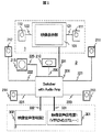
以下、本発明の実施形態について、図面を参照しながら説明する。図1は本発明の一実施形態を示す装置ブロック図である。本実施形態の装置は、映像表示装置1、音声再現装置2及び信号源3を有する。映像表示装置1と音声再現装置2とは、プラグ・アンド・プレイ機能を含む映像音声信号伝送線231で互いに接続されている。この伝送線については、PC(Personal Computer)の本体と表示装置の接続規格であるDDWG(Digital Display Working Group)制定のDVI1.0(Digital Visual Interface version 1.0)、及び独立の音声伝送線を併用したインターフェイスを使用してもよい。またディジタル映像信号とディジタル音声信号を重畳して送信するためのインターフェイス使用してもよい。
Hereinafter, embodiments of the present invention will be described with reference to the drawings. FIG. 1 is an apparatus block diagram showing an embodiment of the present invention. The apparatus according to the present embodiment includes a
尚、以下の本実施形態の説明において、「プラグ・アンド・プレイ機能」とは、信号送信部と信号受信部をケーブル接続した際に、人手を介さずに、信号受信部の特性データを信号送信部が把握して、信号受信部に最適な信号を自動的に送信する機能を指す。 In the following description of the present embodiment, the “plug and play function” means that the characteristic data of the signal receiving unit is transmitted without manual intervention when the signal transmitting unit and the signal receiving unit are connected by cable. It refers to a function that the transmission unit grasps and automatically transmits an optimum signal to the signal reception unit.
本発明の実施形態は、実際に機能できる状態のスピーカを映像音声信号源に知らせるための工夫がなされている。さらには、スピーカ結線の状態が変わった際に、映像音声信号源はこれを知ることができ、動作中でも新しい状態に適した音声出力が得られるようにする工夫が成されている。 The embodiment of the present invention is devised to notify the audio / video signal source of a speaker that can actually function. Further, when the state of speaker connection changes, the video / audio signal source can know this, and a device has been devised so that an audio output suitable for the new state can be obtained even during operation.
まずスイッチャ201は、スピーカケーブル220から225が接続される各端子において、負荷のインピーダンスを測りスピーカ接続の有無を検出する。有無だけであるならば、さほど厳密な測定である必要はなく、出力インピーダンスを有する信号源を設けて、端子に現れる電圧をおおまかに測るような方法でも良い。また、たとえばサブウーハ210などは低音を再生する特殊なスピーカであるから、他のスピーカとは内部インピーダンスを変えて設計し、または入力端子間を容量で短絡して高周波でのインピーダンスを低くするなどすれば、接続の有無のみならず、スピーカの種類も判定でき、誤接続を検出できる。
First, the
なお、後記するように本発明のシステムでは映像表示部101を有することが特徴であるから、検出したスピーカ接続を表示部に図示して表し、誤接続があれば警告表示をすることができる。たとえばリア側のスピーカでRLが接続されていながら、RRが接続されていない場合など、これを警告し、さらにはRL側からRLとRRを加算した信号を出力する旨を、知らせることもできる。
As will be described later, since the system of the present invention is characterized by having the
また、例えばスピーカが5.1チャネル接続されていた場合に、映像表示部101に模式的なスピーカの配置図を出し、各スピーカに試験信号を送り、同時に映像表示部上の当該スピーカを点滅などして表示させ、実際に音の来る方向と矛盾がないかをユーザに確認させる機能を有することで、スピーカの配置ミスも簡単に知ることができる。
Also, for example, when a speaker is connected to 5.1 channels, a schematic speaker layout is displayed on the
次に、スイッチャ201が実際に接続されているスピーカを検出した後、これを映像音声信号源301,302に知らせるための構成について述べる。これはプラグ・アンド・プレイ機能を実現するために、識別子として、例えばVESA(Video Electronics Standards Association)制定のEDID(Extended Display Identification Data)信号に、スピーカ接続の情報を付加することにより行われる。このEDID信号は、周知のように表示装置の仕様(対応可能水平周波数範囲やピクセル数)等を記述したデータであるが、本実施形態は、このEDID信号にスピーカの接続状況に関する情報も付加して映像音声信号源301,302に通知するように構成したものである。
Next, a configuration for informing the audio /
映像音声信号源の要求でスイッチャ−は、EDID信号を送るが、事前にスピーカの検出を行っておけば、スイッチャ201の持つ初期状態のスピーカ配置情報の代わりに、実際に接続されたスピーカの情報に書き換えたEDID信号を送ることができる。またスピーカの検出が終わる前にEDID信号は送出済みとなるならば、検出終了後にホットプラグ機能を用いて、スイッチャ201と映像音声信号源301,302の接続を一旦切断し、再度新たなEDID信号を送るようにする。このためには、EDID信号を送出済みであるか否かを、RAM(Random Access Memory)などに記憶しておいても良い。なおホットプラグ機能は、本来、音声再現装置と映像音声信号源がケーブル接続されたことを示す機能であり、数十ミリ秒程度の切断時間では切断と再接続を認識できないことが考えられるので、確実動作を考えると0.5〜2秒程度の切断時間が望ましく、その切断時間中は装置の機能が中断する。ホットプラグ専用線を独立に用意しておけば、ホットプラグ端子のみを切断する仮想的な切断とすることができ、映像や音声信号の伝送は継続してもかまわない。ホットプラグ機能が無い場合に備え、映像音声信号源が所定の時間例えば0.5〜2秒程度毎にEDIDデータの読み込みを続ける機能を持たせておくと尚好都合である。
At the request of the video / audio signal source, the switcher sends an EDID signal. However, if the speaker is detected in advance, the information of the actually connected speaker is used instead of the initial speaker arrangement information of the
次に、プラグ・アンド・プレイ機能付の映像音声伝送線231に関して述べる。図2の装置ブロック図を参照しながら、FRスピーカ211とFLスピーカ212が接続されていない、あるいは存在しない場合を考える。図中で斜線を付したスピーカはスピーカケーブルで接続されているとする。スピーカケーブル221,222は図中破線で記入し、また×印を付したとおり接続されていないものとする。この二つのスピーカ211,212は正しい音場感を得るうえでは、欠くことのできないものである。そこで、前記したオーディオアンプ付スイッチャ201によるスピーカの検出により、これらが接続されていないことを知った場合、スイッチャ201は映像表示部101へFR,FLチャネルの音声信号を送り、表示部の持つ右スピーカ111と、左スピーカ112で音声を再現できるようにする。これにより、前方の主スピーカがないことによる不具合を解消できる。映像表示部101にスピーカが接続されているか否かは、映像音声伝送線231を介して伝達されるEDID信号を検出することで、スイッチャ201は知ることができる。そのためには、前記したスピーカが実際に接続されているか否かを検出する機能を、映像表示部101にも有すことにより、さらに正しく音声を再現することができる。なお、FRスピーカ211とFLスピーカ212が接続されており、表示部の持つ右スピーカ111と、左スピーカ112を使用する必要のない場合には、映像表示部101に送る音声信号を停止(Mute)し、あるいは無音のデータを送り、あるいは通常よりレベルを下げた音声信号を送るようにすると良い。
Next, a video /
また前記したとおり、図2で示したようなスピーカの配置図を、装置の立上げ時などに映像表示部101に表示し、各スピーカの接続の有無を表すとユーザに分かり易い。このためには、スイッチャ201などに図や文字の表示を行うためのOSD(On Screen Display)回路を設けると良い。
Further, as described above, the speaker layout as shown in FIG. 2 is displayed on the
図2の例では、映像音声信号源301ないし302から5.1チャネルの音声が発生されれば、映像表示部のスピーカ111,112を用いた5.1チャネルの音声再現が可能である。そこで、スピーカ211,212が接続されていないことを検出した際に、図7で模式的に示したような案内を映像表示部101に出しても良い。
In the example of FIG. 2, if 5.1 channel audio is generated from the video /
以上述べた事項の変形として、FR,FLチャネルのスピーカ211,212が接続されていても、Cチャネルの中央スピーカ210が接続されていない場合、スイッチャ201は映像表示部101へCチャネルの音声信号を送り、表示部の持つ右スピーカ111と左スピーカ112、ないしそのいずれか一方で音声を再現できるようにしても良い。これにより、映像表示部101のスピーカを利用した豊かな音場感を得ることができる。
As a modification of the above-described matters, when the FR and
現在はFR,FL,C,RR,RL,Sのチャネルを用いた5.1チャネルの音声を、DVDなどで再生できるが、将来、さらに臨場感を増すために、前右側中央寄りチャネル(FRC)、前左側中央寄りチャネル(FLC)の二つのチャネルを加えた7.1チャネルの音声を使うことが考えられる。FR,FLチャネルのスピーカが接続されている場合には、一般にこれらよりは中央寄りに位置しやすい映像表示部のスピーカを、FRC,FLCチャネルに用いて7.1チャネルの音声を再現すると良い。スイッチャ201は、5.1チャネルのスピーカが接続されていることを前記した方法で検出し、また映像音声伝送線231を介して伝達されるEDID信号を検出して、映像表示部101にスピーカが接続されていることを知り、また映像音声信号源301ないし302から7.1チャネルの音声信号が送られた場合、そのうちFRC,FLCチャネルの音声信号は映像音声伝送線231を介して、映像表示部101へ送られる。なお、以上のようにして7.1チャネルの音声の再現が可能な場合において、映像音声信号源301ないし302からの音声信号が、5.1チャネルである場合には、たとえばスイッチャ201でマトリクス演算を行い、FRC,FLCチャネルの信号を擬似的に作り、映像表示部101へ送っても良い。
Currently, 5.1-channel audio using the FR, FL, C, RR, RL, and S channels can be played on a DVD or the like. ), It is conceivable to use 7.1-channel audio in which two channels of the front left center channel (FLC) are added. When FR and FL channel speakers are connected, it is preferable to reproduce 7.1-channel audio by using a speaker of a video display unit that is generally located closer to the center than these for the FRC and FLC channels. The
なお、以上述べた映像表示部101の持つスピーカ111,112を活用する場合は、これらに供給する音声信号は映像音声伝送線231に乗せ、これ一本で映像信号とともに送ることができるので、スピーカ毎にスピーカケーブルを引き回す必要がなくなり、配線が容易となる効果もある。
When the
次に図3の装置ブロック図を参照しながら、FRチャネルのスピーカ211だけが接続されていない場合を考える。当然ながらこのままでは、正常な音場感は得られない。この場合、スイッチャ201はスピーカ211が接続されていないことを検出したうえで、図8で模式的に示した文字などによるメニューを表示しても良い。ユーザは図中の番号を選択して、たとえばリモートコントローラなどを使い応答する。図8の場合、1を選べば映像表示部(モニタ)に接続されたスピーカ111,112を使って2チャネルステレオで再現する。2を選べばスピーカ211,212は使用せず、スピーカ111,112を主スピーカとして、スピーカ210,213,214,215とともに、5.1チャネルで再現する。3を選べば、ユーザがスピーカ211を接続することを前提にして、スピーカ211〜215を使用して、5.1チャネルで再現する。また4を選べば、ユーザがスピーカ211を接続することを前提にして、スピーカ111,112,211〜215を使用して、7.1チャネルで再現する。ユーザの選択に応じた音声の再現をすることができる効果がある。
Next, a case where only the
このようなメニュー表示とメニュー選択は、スピーカ配置の変化をスピーカ接続検出回路が検出した時点だけでなく、ユーザ指示、例えばリモートコントローラで任意のタイミングで開始できると、スピーカ接続検出回路の誤動作等の対策にもなり、便利である。また、スイッチャにスピーカ接続検出回路を設けず、ユーザ指示だけで行っても良い。 Such menu display and menu selection are not only performed when the speaker connection detection circuit detects a change in the speaker arrangement, but when a user instruction, for example, a remote controller can be started at an arbitrary timing, causes a malfunction of the speaker connection detection circuit. It also becomes a countermeasure and is convenient. Alternatively, the speaker connection detection circuit may not be provided in the switcher, and only the user instruction may be performed.
映像表示部101とオーディオアンプ付スイッチャ201の間で、音声信号に対する利得が異なると正しい臨場感は再現されない。このためには、利得値を規格化し合わせておくことが考えられる。しかし現状はこの規格がなく、特に異なるメーカの装置の間では、これは容易ではない。リモートコントローラは使用者の近辺に置かれるのが普通であるから、これにマイクロフォンを内蔵し、スピーカ毎に音声を発生させてこれを検出し、最適なバランスとなるよう利得を制御する方法が考えられる。また、映像表示部101にスピーカ配置を示す表示を出し、該当するスピーカを点滅するなどして示しながら音声を発生させ、ユーザに最適となるよう調整を依頼する方法もある。また、試験対象スピーカ以外のスピーカをマイクとして動作させることによって、スピーカの配置を推定する方法も考えられる。
If the gain with respect to the audio signal is different between the
たとえばスピーカ111,112も利用して、前記したように7.1チャネルの音声を再現している時、音楽のみのプログラムでは、途中で映像表示部101の電源が切断されることも考えられる。この場合は、映像表示部101の電源が入っている時に7.1チャネル、切れている時に5.1チャネルの音声再現となるよう、出力するチャネル数を切換えると良い。映像表示部101の電源が入っているか否かは、ホットプラグ機能を使った、映像音声伝送線231を介してスピーカ非接続を示すEDID信号の再伝送や、映像表示部101の映像音声入力回路の動作状態を映像音声伝送線231を介してスイッチャ201で検出する方法がある。スイッチャ201が映像表示部の電源が切れている、ないし切れたことを知った時に、スイッチャ201でのマトリクス演算で音声を5.1チャネルに変換して、各スピーカ210〜215へ送るようにしても良い。また前記したホットプラグ機能を用いて、映像音声信号源301ないし302とスイッチャ201の間の接続を一旦切断した後に、新たなEDID信号の授受を行い、映像音声信号源301ないし302から送り出す音声信号を5.1チャネルとしても良い。このようにすれば、常にスピーカの状態に適した音声の再現ができる。
For example, when the 7.1-channel audio is reproduced using the
なお、ホットプラグを用いた切換えは、異なるメーカの装置を用いた場合の互換性を考慮すると、0.5〜2秒程度の時間を見込むことが望ましく、その間装置は機能することができない。同じメーカの装置同士では、設計時に短時間でのホットプラグ動作を考慮した機種であることを確認したうえで、さらに短い時間での切換えを行うことができる。一般に制御信号は映像信号の垂直ブランキング期間に送られるので、ホットプラグ動作による切断時間は、動作マージンを考慮しても、インタレース走査による従来の3フレーム(約200ms)以下とすることができる。これにより切断される時間長を短縮できる効果がある。 It should be noted that the switching using the hot plug is preferably about 0.5 to 2 seconds in consideration of the compatibility when using a device of a different manufacturer, and the device cannot function during that time. The devices of the same manufacturer can be switched in a shorter time after confirming that they are models that consider hot plug operation in a short time at the time of design. In general, since the control signal is sent during the vertical blanking period of the video signal, the disconnection time due to the hot plug operation can be set to 3 frames (about 200 ms) or less in the conventional interlaced scanning even in consideration of the operation margin. . This has the effect of shortening the length of time for cutting.
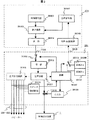
さらに動作開始時に接続されていなかった音声チャネルに、途中でスピーカが接続された場合、そのままでは該当するスピーカから音声を再現することはできない。ユーザの指令などによってホットプラグ機能を動作させ、前記したスピーカ接続の検出を新たに行った結果をEDID信号のせて、装置間で授受することにより、新たに接続したスピーカも機能できる。以上述べたことを実現するための各構成要素のブロック図について、図4、図5、図6を用いて説明する。図4と図5はオーディオアンプ付スイッチャ201と映像音声信号源301(ないし302)を、図6は映像表示部101を示す。
Furthermore, when a speaker is connected to the audio channel that was not connected at the start of the operation, the audio cannot be reproduced from the corresponding speaker as it is. A newly connected speaker can also function by operating the hot plug function according to a user's instruction and the like, and sending and receiving the result of newly detecting the speaker connection described above with an EDID signal between the devices. A block diagram of each component for realizing the above will be described with reference to FIGS. 4, 5, and 6. 4 and 5 show the
まず図4に基づいて述べる。映像音声信号源301は映像信号源30101、音声信号源30102、音声重畳回路30103、送信回路30104、音声チャネル数制御回路30105から成る。なお、スイッチャ201との接続のためのプラグ・アンド・プレイ機能付映像音声伝送線331は、実際は一本のケーブルであるが、表示の都合上331Aと331Bに分けて図示している。
First, a description will be given with reference to FIG. The video /
映像信号源30101は、放送ないしDVDなどの装置から得た映像情報を、音声重畳回路30103へ送る。音声信号源30102はこの映像情報に伴う音声情報を、同じく音声重畳回路30103へ送る。音声信号源30102からの音声情報のチャネル数は、音声チャネル数制御回路30105の指示に応じて決定される。このチャンネル数制御は、テレビジョン放送、DVDなどに含まれている音声データの中から必要なチャネル数を抽出して行う場合もある。また、必要に応じてチャネル数を減らす変換、ないし擬似的に信号を作ってチャネル数を増やす変換が行われることもある。このチャネル数の指示は、後述するようにスイッチャ201から送られるEDID信号で決定される。音声重畳回路30103で多重化された映像信号と音声信号は、送信回路30104を介してスイッチャ201へ送られる。
The
次にオーディオアンプ付スイッチャ201は、スイッチ20101、受信回路20102、音声分離回路20103、加算回路20104、音声出力回路20105、スピーカ接続検出回路20106、制御回路20107、OSD回路20108、第一のEDID発生回路20109、第二のEDID発生回路20110、スイッチ20111、音声重畳回路20112から成る。また映像表示装置1との接続のための、プラグ・アンド・プレイ機能付映像音声伝送線231は、実際は一本のケーブルであるが、表示の都合上二本に分けて図示している。スピーカケーブル220〜225は、図1と同様に各々独立している。
Next, the
プラグ・アンド・プレイ機能付映像音声伝送線331Aより、オーディオアンプ付スイッチャ201へ送られた信号は、まずスイッチ20101に与えられる。これは、前記したプラグ・アンド・プレイ機能のためのスイッチである。たとえば装置の電源立上げ時に接続される装置間で、自分の状態を知らせるためにEDID信号を送る際、あるいは、動作中にスピーカの接続が検出され、また接続が変更されたことを検出してEDID信号を送り際には、一旦(最大2秒程度)スイッチ20101は開路される。開閉のタイミングは制御回路20107より与えられる。通常の使用時は閉路されており、映像音声信号は受信回路20102に与えられる。尚、スイッチ20101の回路は模式的に示したものであり、少なくともホットプラグ端子の開路又はレベル変化があれば、必ずしも映像音声の送受信動作を継続してもかまわない。また、ホットプラグ専用線を映像伝送線と独立に配してもよい。
A signal sent to the
次いで音声分離回路20103で映像信号と音声信号が分離され、前者は加算回路20104へ、後者は音声出力回路20105へ与えられる。また制御回路20107へは、必要に応じて実際に受信された音声信号のチャネル数が知らされる。音声出力回路20105は、たとえば7.1チャネル対応であっても良いが、ここでは図1と同様に5.1チャネル対応とする。
Next, the video signal and the audio signal are separated by the
各チャネルの出力には、本発明によるスピーカ接続検出回路20106が設けられており、スピーカ接続端子のインピーダンスを測定するなどして、接続の有無を検出する。その結果に応じて制御回路20107は、再現するに最適な音声のチャネル数を判定して、スイッチ20111に指示をし、第一のEDID発生回路20109、第二のEDID発生回路20110のうち、最適な音声チャネルを指定できるEDID信号を選択して、映像音声信号源301に送る。もちろん、EDID信号は2種類だけではなく、さらに多数の選択ができるようにしても良い。全てのEDIDデータを複数用意する必要は無く、音声チャネル数に関するEDID部分のみ複数用意して切換えても良い。
A speaker
また制御回路20107は、さきに図7、図8で示したような文字表示、図2、図3で示したような接続図の表示などを行う場合は、OSD回路20108に指示を送り、必要な表示信号を発生させて加算回路20104へ与える。ここで音声分離回路20103からの映像信号へ加算、ないし置換する。なお、OSD回路20108による表示が行われている間、現在放送中の情報を受信しているならば、これを背景画像として重ねて表示しても良いが、DVDなどの再生画像が送られている場合は、これの再生動作を一時停止するようにしても良い。加算回路20104の出力は音声重畳回路20112に与えられる。
In addition, the
先の制御回路20107は、図2、図3などの実施例で示したように映像表示装置1の持つスピーカ111,112を使用して音声を再現する場合は、音声重畳回路20112に指示を出し、必要な1ないし2チャネルの音声信号を映像信号に重畳し、映像表示装置1へ送るようにする。音声信号は映像表示装置1の持つスピーカの接続数に応じて、Cチャネルのみ、あるいはFR,FLの2チャネルを選ぶ。また7.1チャネルの場合はFRC,FLCの2チャネルを選ぶこともあり、また5.1チャネルの音声信号から擬似的にFRC,FLCの2チャネルを作って送ることもある。
The
図4において、スピーカ接続端子の一部から信号を並列に取り出して音声重畳回路20112へ入力する例が記されているが、音声分離回路20103の出力を直接音声重畳回路20112へ入力しても良い。スピーカ接続端子はアナログ信号であることが多く、音声分離回路20103や音声重畳回路20112がディジタルデータを扱う場合に有利である。後述する図10で、音声選択回路20205を経由して音声分離回路20103の出力を音声重畳回路20112へ入力するように構成しても良い。 なお、映像表示装置1の持つスピーカが実際に接続されているか否かは、後記するような映像表示装置1側の類似の手段により、EDID信号として制御回路20107へ伝えられる。これらを基に制御回路20107は、前記した音声重畳回路20112への指示を決定する。
In FIG. 4, an example in which signals are extracted in parallel from a part of the speaker connection terminals and input to the
図5は、本発明において、スピーカの実際の接続は検出するが、映像表示装置1のスピーカを積極的に活用する機能は省略した場合のブロック図を示す。図4と比較して、音声重畳回路20112が省かれている。
FIG. 5 shows a block diagram when the actual connection of the speaker is detected in the present invention, but the function of actively using the speaker of the
図6は本発明における映像表示部101の一実施例を示すブロック図である。図6の構成は、映像表示体10112があり、音声信号が二つのスピーカ111,112へ与えられることを除けば、図4、図5のスイッチャ201と同様であるので、詳しい説明は省略する。ここでは映像表示部101の持つスピーカが実際に接続されているか否かを検出するための、スピーカ接続検出回路10106を有し、その結果を制御回路に送り、さらに実際の接続状態をスイッチャ201に知らせるEDID信号を発生して、前述のとおり最適の音声信号を受信できるようにしたことを特徴としている。プラグ・アンド・プレイの機能のためのスイッチ10101があること、EDID信号の発生回路は二つとは限らないことなどは、さきのスイッチャ201と同様である。
FIG. 6 is a block diagram showing an embodiment of the
以上の説明において、後述する図10でEDID−RAM20206と例示しているように、EDID信号の発生回路をRAM(Random Access Memory)やフラッシュRAMで構成し、その内容をCPUなどで構成される制御回路で書き換えて使うようにすれば、一つの発生回路で、さらに多種の信号を発生することができる。
In the above description, as exemplified by EDID-
次に図9の装置ブロック図を用いて、本発明の別の実施例を述べる。図1と異なる点は、図1のオーディオアンプ付スイッチャ201が、図9ではオーディオアンプ202、スイッチャ203と、別の構成要素に分かれていることである。この場合映像表示部101に信号を供給するプラグ・アンド・プレイ機能付映像音声伝送線231に関しては、これをスイッチャ203に接続すれば、図1と同様な動作が可能である。また、スピーカ210〜215は図1と同様にして、スピーカケーブル220〜225を介して、オーディオアンプ202に接続される。したがいスイッチャ203は、映像音声信号源301,302からの信号を振り分ける機能を有し、映像信号を映像表示部101へ送るほか、音声信号の各チャネルを前記した実施例に示したように、スピーカの実際の接続状況に応じ、オーディオアンプ202と映像表示部101へ分けて送る。
Next, another embodiment of the present invention will be described with reference to the apparatus block diagram of FIG. The difference from FIG. 1 is that the
オーディオアンプ202とスイッチャ203を接続する音声伝送線232が、プラグ・アンド・プレイ機能を持つか否かで動作が変わる。まず機能を持つ場合は、この機能をオーディオアンプ202とスイッチャ203の間で新たに行うことになるが、そのほかは図1の場合と同じである。一方機能を持たない場合は、オーディオアンプ202に実際に接続されるスピーカを、ユーザが装置に知らせるようにする。たとえば、リモコンを用いて接続されているチャネルを入力する、あるいは映像表示部をタッチパネル式にし、図2に示したような表示を出し、接続されているスピーカのマークに触れて入力するなどの方法が考えられる。なお各実施例において、映像表示装置101の持つスピーカが二個である場合を例にとって説明したが、一個、ないし三個以上であっても本発明は適用でき、本発明の記述と同様の発想で、これらを利用した多チャネルの音声再現を実現することができる。
The operation changes depending on whether or not the
次に図10の装置ブロック図を用いて、本発明の別の実施例を述べる。図1におけるオーディオアンプ付スイッチャ201にDVDやSTBなどの映像・音声信号源が内蔵された場合を想定したものである。図10において、20201は映像信号源、20202は音声信号源、20203は映像信号切換えスイッチ、20204は音声信号切換えスイッチ、20205音声選択回路、20109はEDID−RAMである、図4に示したものと同じ構成要素でも良いものは、同じ番号を付して示している。
Next, another embodiment of the present invention will be described with reference to the apparatus block diagram of FIG. It is assumed that a video / audio signal source such as a DVD or STB is built in the
図10では、EDID−RAM20109を用いているが、図4の説明でもふれた通り、図4の複数のEDIDを切換えるものと同様な働きをする。また、音声選択回路20205を設けて、音声分離回路20103の出力から映像表示装置1へ伝送する音声信号を抽出して音声重畳回路20112へ送っているが、基本的に図4と同様な動作である、特に、外部の信号源301に対しては、図4と同様な動作なので、動作説明は省略する。
In FIG. 10, the EDID-
スイッチ20203と20204が内部の映像信号源20201の映像出力と内部の音声信号源20202の音声出力を選択する場合は、EDIDデータのやりとりは必要無く、直接制御回路20107が音声信号源20202を直接制御(図示せず)して最適な音声チャネル再生数を設定する。他は外部信号源301と同様な動作となるので、省略する。
When the
次に図11の装置ブロック図を用いて、本発明の別の実施例を述べる。図1におけるオーディオアンプ付スイッチャ201にヘッドホン端子を設けた場合である。図11において、226はスイッチャ201のヘッドホン端子(図示せず)とヘッドホンを接続するヘッドホンケーブル、20207はヘッドホン検出回路である。図10に示したものと同じ構成要素でも良いものは、同じ番号を付して示している。基本動作は図10と同様なので省略し、ヘッドホン接続動作に絞って以下,説明する。
Next, another embodiment of the present invention will be described using the apparatus block diagram of FIG. This is a case where the headphone terminal is provided in the
ヘッドホン端子にヘッドホンが接続されると、ヘッドホン検出回路20207が、機械的な接点の開閉あるいはヘッドホンのインピーダンス検出により、ヘッドホンの接続を検出する。ヘッドホン検出信号が音声出力回路20105及び音声選択回路20205へ入力され、スピーカケーブル220〜225への音声出力及び音声重畳回路20112への音声出力を止める(無音化する)ものである。これにより、スイッチャ201に接続されたスピーカや映像表示装置1に接続されたスピーカ全ての音出力を停止させることができる。映像表示装置に接続された音を止める場合は、上記の音声重畳回路20112の入力を無音化する以外に、映像表示装置1の音量を下げるよう制御信号を映像表示装置に送る方法もある。
When a headphone is connected to the headphone terminal, the headphone detection circuit 20207 detects the connection of the headphone by opening / closing a mechanical contact or detecting the impedance of the headphone. The headphone detection signal is input to the
ここで、例えばヘッドホン接続前に5.1chのスピーカ配置を取っていたとすると、接続されたヘッドホンがステレオやモノラルかなど音声再生チャネル数が減る。このチャネル数の変化を制御20107経由で20206のEDID−RAMのスピーカ配置情報を書換えると共に、スイッチ20101のホットプラグ機能を用いて、信号源301へ知らせ、ヘッドホンに適した音声データを信号源301が出力するものである。
Here, for example, if a 5.1-channel speaker arrangement is taken before the headphones are connected, the number of audio reproduction channels such as whether the connected headphones are stereo or monaural is reduced. This change in the number of channels is rewritten to the speaker arrangement information of the EDID-
次に図12の映像表示部のブロック図を用いて、本発明の別の実施例を述べる。図1における映像表示部101にヘッドホン端子を設けた場合である。図12において、123は映像表示部101のヘッドホン端子(図示せず)とヘッドホンを接続するヘッドホンケーブル、10113はヘッドホン検出回路、10114はEDID−RAMである。図6のEDID−1とEDID−2をスイッチ10111で切換える部分は図10の実施例と同様にEDID−RAMで代用している。その他、図6に示したものと同じ構成要素でも良いものは、同じ番号を付して示している。基本動作は図6と同様なので省略し、ヘッドホン接続動作に絞って以下、説明する。
Next, another embodiment of the present invention will be described using the block diagram of the video display unit of FIG. This is a case where a headphone terminal is provided in the
ヘッドホン端子にヘッドホンが接続されると、ヘッドホン検出回路10113が、機械的な接点の開閉あるいはヘッドホンのインピーダンス検出により、ヘッドホンの接続を検出する。ヘッドホン検出信号が音声出力回路10105へ入力され、スピーカケーブル121,122への音声出力を止める(無音化する)ものである。これにより、映像表示部101に接続されたスピーカの音出力を停止させることができる。
When a headphone is connected to the headphone terminal, the
ここで、例えばヘッドホン接続前にスピーカが接続されていなかったとすると、ヘッドホンを接続したことにより、音声再現機能が付加されてことになる。この変化を制御10107経由で10114のEDID−RAMのスピーカ配置情報を書換えると共に、スイッチ210101のホットプラグ機能を用いて、音声出力装置やスイッチャなどの音声処理装置(図示せず)へ知らせ、ヘッドホンに適した音声データを映像表示部が受け取り、ヘッドホンで音再現するものである。また、プラグ・アンド・プレイ機能付映像音声伝送線231に接続された音声処理装置がスピーカが接続されたオーディオアンプであるとすると、これらのスピーカの音出力も同時に停止させる必要がある。このためには、前述したEDID−RAMのスピーカ配置情報の書換えでオーディオアンプへ知らせることができる。
Here, for example, if the speaker is not connected before the headphones are connected, the sound reproduction function is added by connecting the headphones. The change of the speaker arrangement information of the EDID-
また、図示していないが、専用の制御線やリモコンを併用すれば、オーディオアンプを直接制御してスピーカを無音化することができる。制御線やリモコン併用する方法は、映像表示部101にステレオスピーカが接続されている時に、ステレオヘッドホンが接続されると、EDID−RAMのスピーカ配置が同一であるため区別できなくなる際に有効である。
Although not shown, if a dedicated control line or remote control is used in combination, the audio amplifier can be directly controlled to silence the speaker. The method using the control line or the remote control is effective when the stereo speakers are connected to the
以上の実施形態の説明では、スイッチャ201が映像音声信号源301や302、または映像表示装置1と分離されているが、映像音声信号源301や302または映像表示装置1がスイッチャ201内蔵する構成でもよい。この場合、スイッチャ201から映像音声信号源301や302に対し接続情報を送信する構成は省かれるが、検出された接続状態に応じたチャネル数制御の構成は、前述の実施例と変わらない。
In the above description of the embodiment, the
更に、テレビジョン放送信号に番組情報が重畳されている場合には、その番組情報に基づき音声のチャネル数制御を行ってもよい。番組情報は、電子番組ガイドをディスプレイ上に表示するために用いられる。この番組ガイドは、通常、各チャンネルの将来における番組のスケジュールを表す。また、番組情報は、番組のタイトル、放送局名(Ch番号)、番組の放送開始及び終了時刻、その番組の種類(映画、ニュース、ドラマ等)、その番組で再生される音声のチャネル数に関するデータを含んでいる。 Furthermore, when program information is superimposed on a television broadcast signal, the number of audio channels may be controlled based on the program information. Program information is used to display an electronic program guide on a display. This program guide typically represents the future program schedule for each channel. The program information relates to the program title, broadcast station name (Ch number), program broadcast start and end times, the type of program (movie, news, drama, etc.), and the number of audio channels played in the program. Contains data.
番組がニュースの場合は2Chの音声信号が、映画や音楽番組であれば、5.1Chもしくは7.1Chの音声信号が、それぞれの番組の放送信号に重畳される場合が多い。よって、ニュースの放送信号に対しては、音声チャネル数が2Chであることを示すデータが、映画や音楽番組の放送信号に対しては音声チャネル数が5.1Chもしくは7.1Chであることを示すデータが付加される。 If the program is news, the audio signal of 2Ch is often superimposed on the broadcast signal of each program if the audio signal of 5.1Ch or 7.1Ch is a movie or music program. Therefore, data indicating that the number of audio channels is 2Ch for broadcast signals of news, and that the number of audio channels is 5.1Ch or 7.1Ch for broadcast signals of movies and music programs. The indicated data is added.
従って、本発明の他の実施形態として、ユーザが選局した番組の放送信号から番組情報を抜き出し、その抜き出された番組情報に含まれる音声チャンネル数のデータに従って、音声Ch数制御回路で音声信号源30102を制御するようにしてもよい。従って、ニュース番組を選局し、その放送信号に音声チャネル数が2Chであることを示すデータが付加されたいる場合は、たとえ装置が5.1Chのスピーカを有する場合でも2Chで音声が再生される。一方、映画番組を選局し、その放送信号に音声チャネル数が5.1Chであることを示すデータが付加され、かつ装置が5.1Chのスピーカを有する場合は、全てのスピーカを活用して音声の再生を行う。このように構成することによって、番組の内容に応じた、自動的な音声チャネル数制御が実現できる。
Therefore, as another embodiment of the present invention, the program information is extracted from the broadcast signal of the program selected by the user, and the audio Ch number control circuit performs audio according to the data of the number of audio channels included in the extracted program information. The
更に、本発明では、2Chの音声信号しか付加されていない映画も、その番組が上記番組情報に含まれる番組種類のデータで「映画」であることが判明すれば、その番組を5.1Chで擬似再生することが可能である。また、7.1Chの音声信号しか付加されているニュースでも、その番組が上記番組情報に含まれる番組種類のデータで「ニュース」であることが判明すれば、その番組を2Chで擬似再生することも可能である。すなわち、この実施形態では、再生すべき音声チャネル数を決定するためのデータとして、番組情報に含まれるチャネル数データよりも、番組種別のデータを優先して用いることを特徴とするものである。 Furthermore, in the present invention, even if a movie to which only a 2Ch audio signal is added is found that the program is “movie” in the program type data included in the program information, the program is reduced to 5.1 Ch. Pseudo reproduction is possible. In addition, even in news to which only 7.1 Ch audio signals are added, if it is found that the program is “news” in the data of the program type included in the program information, the program is simulated and reproduced in 2 Ch. Is also possible. That is, in this embodiment, data for determining the number of audio channels to be reproduced is used with priority given to data of the program type over the data of the number of channels included in the program information.
より具体的に説明すれば、テレビジョン放送信号を受信する回路を備えた映像音声信号源301は、受信番組の番組情報中の番組情報が「映画」を示す場合は5.1Chもしくは7.1Chで音声を再生し、番組情報が「ニュース」を示す場合は2Chで音声を再生するためのデータを予め記憶する。つまり、番組の種類に対応した適切な再生音声チャンネル数のデータを、番組の種類毎に予め設定してテーブルを構成する。このテーブル内のデータを、再生される音声チャネル数の初期設定として用いる。上記テーブルは、図示しないマイクロコンピュータ内のメモリ、または別のメモリに格納してもよい。映像音声信号源301(に内蔵されるマイクロコンピュータ)は、受信したテレビジョン放送信号から番組情報を抽出し、その番組情報中に含まれる番組種類のデータの内容を判別する。その判別結果は、上記メモリに格納されたテーブルと参照され、そしてマイクロコンピュータは、判別した番組種類と対応する再生音声チャネル数のデータを、上記メモリから読み出す。この再生音声チャネル数のデータを使用して、番組音声Ch数制御回路は、音声信号源30102を制御して再生される音声のチャンネル数を制御する。このような構成により、番組の種類に応じた、適切なチャネル数で音声を再生することが可能となる。上記テーブルを使用した再生音声チャネル数制御は、ユーザが許可/禁止を選択できるようにしてもよい。その場合は、OSD回路を用いて、その選択に関するメッセージをディスプレイ上に表示し、ユーザと対話的に行うようにすることが好ましい。
More specifically, the video /
1…映像表示装置、101…映像表示部、111…表示部の持つ右スピーカ(R)、112…表示部の持つ左スピーカ(L)、121,122…スピーカケーブル、2…音声再現装置、201…オーディオアンプ付スイッチャ、202…オーディオアンプ、203…スイッチャ、210…スイッチャに接続された中央スピーカ(C)、211…スイッチャに接続された前右スピーカ(FR)、212…スイッチャに接続された前左スピーカ(FL)、213…スイッチャに接続された後右スピーカ(RR)、214…スイッチャに接続された後左スピーカ(RL)、215…スイッチャに接続されたサブウーハ(S)、221〜225…スピーカケーブル、231…プラグ・アンド・プレイ機能付映像音声伝送線、232…音声伝送線、3…信号源、301…映像音声信号源、302…映像音声信号源、331,332…プラグ・アンド・プレイ機能付映像音声伝送線。
DESCRIPTION OF
Claims (4)
前記送信装置は、映像信号と音声信号とを重畳して前記受信装置に送信する送信部と、前記送信部から送信する音声信号のチャンネル数を制御するチャンネル数制御部とを有し、
前記受信装置は、前記送信装置から送信される映像信号と音声信号とを受信する受信部と、スピーカの接続状態を示す接続状態情報を記録する記録部と、前記送信装置との接続状態を変化させるホットプラグ手段とを有し、
前記受信装置の記録部に記録された接続状態情報が変更されると、前記受信装置は前記ホットプラグ手段により前記送信装置との接続を所定時間切断状態とした後で変更された接続状態情報を前記送信装置に送信し、前記送信装置は受信した接続状態情報に応じて前記送信部から送信する音声信号のチャンネル数を制御することを特徴とする映像音声信号送受信システム。 A video / audio signal transmission / reception system including a transmission device that superimposes and transmits a video signal and an audio signal, and a reception device that receives the video signal and the audio signal transmitted from the transmission device,
The transmission device includes a transmission unit that superimposes a video signal and an audio signal and transmits the signal to the reception device, and a channel number control unit that controls the number of channels of the audio signal transmitted from the transmission unit,
The receiving device changes a connection state between the receiving unit that receives a video signal and an audio signal transmitted from the transmitting device, a recording unit that records connection state information indicating a connection state of a speaker, and the transmitting device. And hot plug means
When the connection state information recorded in the recording unit of the receiving device is changed, the receiving device displays the changed connection state information after the hot plug means disconnects the connection with the transmitting device for a predetermined time. The video / audio signal transmission / reception system, wherein the transmission apparatus controls the number of channels of the audio signal transmitted from the transmission unit according to the received connection state information.
前記受信装置は、接続されるスピーカを検出するスピーカ検出部を有し、
前記受信装置のスピーカ検出部が接続されるスピーカの状態が変更されたことを検出すると、前記受信装置の記録部に記録された接続状態情報の変更が行われることを特徴とする映像音声信号送受信システム。 The video / audio signal transmission / reception system according to claim 1,
The receiving device includes a speaker detection unit that detects a connected speaker;
A video / audio signal transmission / reception characterized in that when the state of a speaker to which the speaker detection unit of the receiving device is connected is detected, the connection state information recorded in the recording unit of the receiving device is changed. system.
前記送信装置から送信する音声信号のチャンネル数を制御するステップと、
前記送信装置から映像信号とチャンネル数を制御された音声信号とを重畳して送信するステップと、
前記受信装置で前記送信された映像信号と音声信号とを受信するステップと、
前記受信装置に接続するスピーカの接続状態を示す接続状態情報を記録するステップと、
前記送信装置と前記受信装置との接続状態を変化させるステップとを有し、
前記記録した接続状態情報を変更すると、前記送信装置と前記受信装置との接続を所定時間切断状状態とした後で変更した接続状態情報を前記受信装置から前記送信装置に送信し、送信された接続状態情報に応じて前記送信装置から送信する音声信号のチャンネル数を制御することを特徴とする映像音声信号送受信方法。 A video / audio signal transmission / reception method in which a video signal and an audio signal are superimposed and transmitted from a transmission device, and the transmitted video signal and audio signal are received by a reception device,
Controlling the number of channels of the audio signal transmitted from the transmitting device;
Transmitting the video signal and the audio signal of which the number of channels is controlled from the transmitting device,
Receiving the transmitted video signal and audio signal at the receiving device;
Recording connection state information indicating a connection state of a speaker connected to the receiving device ;
Changing a connection state between the transmitting device and the receiving device ,
When the recorded connection state information is changed, the connection state information changed after the connection between the transmission device and the reception device is disconnected for a predetermined time is transmitted from the reception device to the transmission device, and transmitted. A video / audio signal transmission / reception method characterized by controlling the number of channels of an audio signal transmitted from the transmission device according to connection state information.
前記受信装置において当該受信装置に接続するスピーカの状態が変更されたことを検出すると、前記記録した接続状態情報を変更することを特徴とする映像音声信号送受信方法。 The video / audio signal transmitting / receiving method according to claim 3,
A video / audio signal transmission / reception method, wherein when the reception device detects that the state of a speaker connected to the reception device is changed, the recorded connection state information is changed.
Priority Applications (1)
| Application Number | Priority Date | Filing Date | Title |
|---|---|---|---|
| JP2009255676A JP4530108B2 (en) | 2002-03-29 | 2009-11-09 | Video display device, audio output method, audio amplifier device, and video / audio output system |
Applications Claiming Priority (2)
| Application Number | Priority Date | Filing Date | Title |
|---|---|---|---|
| JP2002093545 | 2002-03-29 | ||
| JP2009255676A JP4530108B2 (en) | 2002-03-29 | 2009-11-09 | Video display device, audio output method, audio amplifier device, and video / audio output system |
Related Parent Applications (1)
| Application Number | Title | Priority Date | Filing Date |
|---|---|---|---|
| JP2007010957A Division JP4501941B2 (en) | 2002-03-29 | 2007-01-22 | Audio processing apparatus and audio processing method |
Related Child Applications (2)
| Application Number | Title | Priority Date | Filing Date |
|---|---|---|---|
| JP2010023713A Division JP4935912B2 (en) | 2002-03-29 | 2010-02-05 | Video display device, audio output method, and video / audio output system |
| JP2010095614A Division JP2010200351A (en) | 2002-03-29 | 2010-04-19 | Video/audio signal transmitting/receiving method |
Publications (3)
| Publication Number | Publication Date |
|---|---|
| JP2010035216A JP2010035216A (en) | 2010-02-12 |
| JP2010035216A5 JP2010035216A5 (en) | 2010-03-25 |
| JP4530108B2 true JP4530108B2 (en) | 2010-08-25 |
Family
ID=28449660
Family Applications (3)
| Application Number | Title | Priority Date | Filing Date |
|---|---|---|---|
| JP2009255676A Expired - Lifetime JP4530108B2 (en) | 2002-03-29 | 2009-11-09 | Video display device, audio output method, audio amplifier device, and video / audio output system |
| JP2010023713A Expired - Lifetime JP4935912B2 (en) | 2002-03-29 | 2010-02-05 | Video display device, audio output method, and video / audio output system |
| JP2010095614A Pending JP2010200351A (en) | 2002-03-29 | 2010-04-19 | Video/audio signal transmitting/receiving method |
Family Applications After (2)
| Application Number | Title | Priority Date | Filing Date |
|---|---|---|---|
| JP2010023713A Expired - Lifetime JP4935912B2 (en) | 2002-03-29 | 2010-02-05 | Video display device, audio output method, and video / audio output system |
| JP2010095614A Pending JP2010200351A (en) | 2002-03-29 | 2010-04-19 | Video/audio signal transmitting/receiving method |
Country Status (2)
| Country | Link |
|---|---|
| US (6) | US20030185400A1 (en) |
| JP (3) | JP4530108B2 (en) |
Families Citing this family (98)
| Publication number | Priority date | Publication date | Assignee | Title |
|---|---|---|---|---|
| US20030185400A1 (en) * | 2002-03-29 | 2003-10-02 | Hitachi, Ltd. | Sound processing unit, sound processing system, audio output unit and display device |
| US11106425B2 (en) | 2003-07-28 | 2021-08-31 | Sonos, Inc. | Synchronizing operations among a plurality of independently clocked digital data processing devices |
| US9207905B2 (en) | 2003-07-28 | 2015-12-08 | Sonos, Inc. | Method and apparatus for providing synchrony group status information |
| US11294618B2 (en) | 2003-07-28 | 2022-04-05 | Sonos, Inc. | Media player system |
| US8086752B2 (en) | 2006-11-22 | 2011-12-27 | Sonos, Inc. | Systems and methods for synchronizing operations among a plurality of independently clocked digital data processing devices that independently source digital data |
| US11650784B2 (en) | 2003-07-28 | 2023-05-16 | Sonos, Inc. | Adjusting volume levels |
| US8234395B2 (en) | 2003-07-28 | 2012-07-31 | Sonos, Inc. | System and method for synchronizing operations among a plurality of independently clocked digital data processing devices |
| US11106424B2 (en) | 2003-07-28 | 2021-08-31 | Sonos, Inc. | Synchronizing operations among a plurality of independently clocked digital data processing devices |
| US8290603B1 (en) | 2004-06-05 | 2012-10-16 | Sonos, Inc. | User interfaces for controlling and manipulating groupings in a multi-zone media system |
| US7526093B2 (en) * | 2003-08-04 | 2009-04-28 | Harman International Industries, Incorporated | System for configuring audio system |
| JP2005109703A (en) * | 2003-09-29 | 2005-04-21 | Pioneer Electronic Corp | Apparatus and method for outputting image, image display system, image output program and information recording medium |
| TWI279153B (en) * | 2004-02-27 | 2007-04-11 | Lg Electronics Inc | Apparatus and method for controlling operation of audio low sound output means |
| US9977561B2 (en) | 2004-04-01 | 2018-05-22 | Sonos, Inc. | Systems, methods, apparatus, and articles of manufacture to provide guest access |
| US8024055B1 (en) | 2004-05-15 | 2011-09-20 | Sonos, Inc. | Method and system for controlling amplifiers |
| WO2005117647A1 (en) | 2004-05-28 | 2005-12-15 | Wms Gaming Inc. | Gaming device with attached audio-capable chair |
| WO2005117648A1 (en) * | 2004-05-28 | 2005-12-15 | Wms Gaming Inc. | Chair interconnection for a gaming machine |
| US8326951B1 (en) | 2004-06-05 | 2012-12-04 | Sonos, Inc. | Establishing a secure wireless network with minimum human intervention |
| US8868698B2 (en) | 2004-06-05 | 2014-10-21 | Sonos, Inc. | Establishing a secure wireless network with minimum human intervention |
| EP1617699A3 (en) * | 2004-07-12 | 2013-11-27 | Sony Corporation | Flat panel display apparatus, stand and speaker apparatus |
| US20060089735A1 (en) * | 2004-10-21 | 2006-04-27 | Atkinson Lee W | Method and apparatus for configuring the audio outputs of an electronic device |
| CN101951446B (en) * | 2004-10-25 | 2016-11-23 | 诺基亚技术有限公司 | It is connected to the detection of the ancillary equipment of electronic equipment via audio/video plug, identifies and operate |
| CN101129069B (en) * | 2004-11-25 | 2010-12-22 | 松下电器产业株式会社 | Repeater apparatus and method for controlling the same |
| JP4904693B2 (en) * | 2005-02-02 | 2012-03-28 | 船井電機株式会社 | Television receiver |
| US20060199645A1 (en) * | 2005-02-28 | 2006-09-07 | Canterbury Stephen A | Wagering game with streaming usb audio |
| KR20060109770A (en) * | 2005-04-18 | 2006-10-23 | 엘지전자 주식회사 | Sound output control method for audio device |
| JP4092702B2 (en) * | 2005-04-20 | 2008-05-28 | 船井電機株式会社 | Optical disk playback device and plug adapter |
| KR100713849B1 (en) * | 2005-06-14 | 2007-05-04 | 삼성전자주식회사 | Display apparatus and control method thereof |
| JP2007058930A (en) * | 2005-08-22 | 2007-03-08 | Funai Electric Co Ltd | Disk playback device |
| JP4487316B2 (en) * | 2005-09-21 | 2010-06-23 | オンキヨー株式会社 | Video signal and multi-channel audio signal transmission signal processing apparatus and video / audio reproduction system including the same |
| EP1931140B1 (en) * | 2005-09-29 | 2014-07-16 | Panasonic Corporation | Video/sound output device and external speaker control device |
| JP4299822B2 (en) * | 2005-09-30 | 2009-07-22 | パナソニック株式会社 | Video / audio output device and external speaker control device |
| JP4674520B2 (en) * | 2005-10-11 | 2011-04-20 | ソニー株式会社 | Information processing apparatus and method, and program |
| JP5145633B2 (en) * | 2005-10-31 | 2013-02-20 | パナソニック株式会社 | Sound reproduction apparatus and video / audio viewing system |
| WO2007052625A1 (en) * | 2005-10-31 | 2007-05-10 | Matsushita Electric Industrial Co., Ltd. | Audiovisual system |
| JP4794983B2 (en) * | 2005-10-31 | 2011-10-19 | パナソニック株式会社 | Audio output system control method and audio output system |
| KR100888474B1 (en) | 2005-11-21 | 2009-03-12 | 삼성전자주식회사 | Apparatus and method for encoding/decoding multichannel audio signal |
| US9319741B2 (en) | 2006-09-07 | 2016-04-19 | Rateze Remote Mgmt Llc | Finding devices in an entertainment system |
| US8607281B2 (en) * | 2006-09-07 | 2013-12-10 | Porto Vinci Ltd. Limited Liability Company | Control of data presentation in multiple zones using a wireless home entertainment hub |
| US8483853B1 (en) | 2006-09-12 | 2013-07-09 | Sonos, Inc. | Controlling and manipulating groupings in a multi-zone media system |
| US8788080B1 (en) | 2006-09-12 | 2014-07-22 | Sonos, Inc. | Multi-channel pairing in a media system |
| US9202509B2 (en) | 2006-09-12 | 2015-12-01 | Sonos, Inc. | Controlling and grouping in a multi-zone media system |
| US7933485B2 (en) * | 2006-12-14 | 2011-04-26 | Panasonic Corporation | Audio-video output device, audio output device, audio-video reproduction device, audio-video data reproduction system, and audio-video data reproduction method |
| US8705748B2 (en) * | 2007-05-04 | 2014-04-22 | Creative Technology Ltd | Method for spatially processing multichannel signals, processing module, and virtual surround-sound systems |
| KR101445637B1 (en) * | 2007-06-14 | 2014-10-01 | 삼성전자주식회사 | Method for checking Audio Interface in AV system and apparatus thereof |
| JP2008312034A (en) * | 2007-06-15 | 2008-12-25 | Panasonic Corp | Sound signal reproduction device, and sound signal reproduction system |
| US8351624B2 (en) * | 2007-06-18 | 2013-01-08 | Sony Corporation | Audio output apparatus, audio input apparatus, audio control apparatus, audio control system, and audio control method |
| WO2009010056A1 (en) * | 2007-07-16 | 2009-01-22 | The Tc Group A/S | Method of determining a class of a load connected to an amplifier output |
| JP4920522B2 (en) * | 2007-08-06 | 2012-04-18 | 株式会社東芝 | Information processing apparatus and output interlocking control method |
| JP5040528B2 (en) * | 2007-08-28 | 2012-10-03 | ソニー株式会社 | Audio signal transmitting apparatus, audio signal receiving apparatus, and audio signal transmission method |
| JP2009065391A (en) * | 2007-09-05 | 2009-03-26 | Toshiba Corp | Video processing apparatus and video processing method |
| TWM333021U (en) * | 2007-12-18 | 2008-05-21 | Princeton Technology Corp | Audio playing apparatus |
| US20090292377A1 (en) * | 2008-04-17 | 2009-11-26 | Panasonic Corporation | Multi-channel audio output device |
| JP2010057085A (en) * | 2008-08-29 | 2010-03-11 | Canon Inc | Tv receiver and control method thereof |
| JP5055254B2 (en) | 2008-12-19 | 2012-10-24 | 日立コンシューマエレクトロニクス株式会社 | Video transmission system and EDID reading method |
| JP5645370B2 (en) | 2009-04-23 | 2014-12-24 | 日立マクセル株式会社 | Video equipment |
| US8599235B2 (en) * | 2009-07-27 | 2013-12-03 | Cisco Technology, Inc. | Automatic display latency measurement system for video conferencing |
| JP5531486B2 (en) * | 2009-07-29 | 2014-06-25 | ヤマハ株式会社 | Audio equipment |
| JP5246111B2 (en) | 2009-09-04 | 2013-07-24 | ヤマハ株式会社 | Audio equipment |
| US9165394B2 (en) * | 2009-10-13 | 2015-10-20 | Nvidia Corporation | Method and system for supporting GPU audio output on graphics processing unit |
| JP2011124925A (en) * | 2009-12-14 | 2011-06-23 | Sony Corp | Output control apparatus, output control method, program, and output control system |
| JP2012047842A (en) * | 2010-08-25 | 2012-03-08 | Seiko Epson Corp | Image display device, and image display method |
| JP2012047843A (en) * | 2010-08-25 | 2012-03-08 | Seiko Epson Corp | Control device, image display device, and control method |
| US20120105603A1 (en) * | 2010-11-02 | 2012-05-03 | Hsuan-Ching Liu | Display system with dynamic 3d sound reproduction and related method |
| CN102595153A (en) * | 2011-01-13 | 2012-07-18 | 承景科技股份有限公司 | Display system for dynamically supplying three-dimensional sound effects and relevant method |
| US11429343B2 (en) | 2011-01-25 | 2022-08-30 | Sonos, Inc. | Stereo playback configuration and control |
| US11265652B2 (en) | 2011-01-25 | 2022-03-01 | Sonos, Inc. | Playback device pairing |
| US8938312B2 (en) | 2011-04-18 | 2015-01-20 | Sonos, Inc. | Smart line-in processing |
| JP2012248257A (en) * | 2011-05-31 | 2012-12-13 | Funai Electric Co Ltd | Video and audio device, and video and audio system provided with the same |
| US9042556B2 (en) | 2011-07-19 | 2015-05-26 | Sonos, Inc | Shaping sound responsive to speaker orientation |
| US9729115B2 (en) | 2012-04-27 | 2017-08-08 | Sonos, Inc. | Intelligently increasing the sound level of player |
| US8903526B2 (en) | 2012-06-06 | 2014-12-02 | Sonos, Inc. | Device playback failure recovery and redistribution |
| KR101956161B1 (en) * | 2012-08-30 | 2019-03-08 | 삼성전자 주식회사 | Method and apparatus for controlling audio output |
| US9008330B2 (en) | 2012-09-28 | 2015-04-14 | Sonos, Inc. | Crossover frequency adjustments for audio speakers |
| TWI507048B (en) * | 2012-11-09 | 2015-11-01 | Giga Byte Tech Co Ltd | Multiple sound channels speaker |
| CN103813240B (en) * | 2012-11-09 | 2016-08-24 | 技嘉科技股份有限公司 | Multichannel loudspeaker |
| KR102052372B1 (en) * | 2013-01-11 | 2019-12-05 | 엘지전자 주식회사 | Apparatus and Method for transmitting and receiving data using earphone |
| US9118998B2 (en) * | 2013-02-07 | 2015-08-25 | Giga-Byte Technology Co., Ltd. | Multiple sound channels speaker |
| JP6228387B2 (en) * | 2013-05-14 | 2017-11-08 | 日本放送協会 | Acoustic signal reproduction device |
| US9244516B2 (en) | 2013-09-30 | 2016-01-26 | Sonos, Inc. | Media playback system using standby mode in a mesh network |
| US9226073B2 (en) | 2014-02-06 | 2015-12-29 | Sonos, Inc. | Audio output balancing during synchronized playback |
| US9226087B2 (en) | 2014-02-06 | 2015-12-29 | Sonos, Inc. | Audio output balancing during synchronized playback |
| JP6330905B2 (en) | 2014-05-26 | 2018-05-30 | ヤマハ株式会社 | Connection confirmation system, connection confirmation program, connection confirmation method, and connection detection device |
| KR102320742B1 (en) * | 2014-06-03 | 2021-11-03 | 삼성전자주식회사 | Broadcast receiving apparatus and method for outputting a audio |
| WO2015186951A1 (en) * | 2014-06-03 | 2015-12-10 | Samsung Electronics Co., Ltd. | Broadcast receiving apparatus and audio output method thereof |
| US10248376B2 (en) | 2015-06-11 | 2019-04-02 | Sonos, Inc. | Multiple groupings in a playback system |
| TW201721473A (en) * | 2015-12-11 | 2017-06-16 | 富奇想股份有限公司 | Intelligent system |
| CN105632542B (en) * | 2015-12-23 | 2019-05-28 | 小米科技有限责任公司 | Audio frequency playing method and device |
| CN105847715A (en) * | 2016-01-20 | 2016-08-10 | 乐视致新电子科技(天津)有限公司 | Multimedia playing device |
| US10713663B2 (en) * | 2016-03-29 | 2020-07-14 | Authentix, Inc. | Product authentication using barcode characteristics |
| US10712997B2 (en) | 2016-10-17 | 2020-07-14 | Sonos, Inc. | Room association based on name |
| CN106658291A (en) * | 2016-12-21 | 2017-05-10 | 捷开通讯(深圳)有限公司 | Audio device and method for switching stereo and single track external play |
| KR102553250B1 (en) * | 2017-09-22 | 2023-07-10 | 삼성전자주식회사 | Electronic apparatus, method for controlling thereof and the computer readable recording medium |
| CN108804071B (en) * | 2018-05-29 | 2021-12-14 | 维沃移动通信有限公司 | Receiver driving method and mobile terminal |
| US11504626B2 (en) * | 2018-11-29 | 2022-11-22 | Ts Tech Co., Ltd. | Seat system and seat experience device |
| KR102630446B1 (en) * | 2019-08-02 | 2024-01-31 | 삼성전자주식회사 | Display apparatus, audio apparatus and method for controlling thereof |
| US20220295206A1 (en) * | 2019-08-09 | 2022-09-15 | Lg Electronics Inc. | Display device and operating method thereof |
| CN113810830A (en) * | 2020-06-17 | 2021-12-17 | 苏州佳世达电通有限公司 | Sound playing system |
| CN116609706B (en) * | 2023-07-19 | 2023-09-19 | 北京同方艾威康科技有限公司 | VGA image quality nondestructive disconnection detection method |
Citations (9)
| Publication number | Priority date | Publication date | Assignee | Title |
|---|---|---|---|---|
| JPH0358682A (en) * | 1989-07-27 | 1991-03-13 | Sanyo Electric Co Ltd | Television receiver provided with display function for external speaker state |
| JPH0348999U (en) * | 1989-09-20 | 1991-05-13 | ||
| JPH10215500A (en) * | 1997-01-30 | 1998-08-11 | Matsushita Electric Ind Co Ltd | Multi-channel audio output circuit for television receiver |
| JPH10334650A (en) * | 1997-05-27 | 1998-12-18 | Kenwood Corp | Digital audio system |
| JPH11231878A (en) * | 1998-02-13 | 1999-08-27 | Yamaha Corp | Control method for sound field treatment |
| JPH11355880A (en) * | 1998-06-12 | 1999-12-24 | Sharp Corp | Acoustic reproducing device |
| JP2000023300A (en) * | 1998-07-06 | 2000-01-21 | Victor Co Of Japan Ltd | Automatic sound system setting device |
| JP2001356752A (en) * | 2000-06-14 | 2001-12-26 | Nanao Corp | Distribution device for display device |
| JP2002023719A (en) * | 2000-07-04 | 2002-01-25 | Canon Inc | Device and method for image processing, and recording medium |
Family Cites Families (42)
| Publication number | Priority date | Publication date | Assignee | Title |
|---|---|---|---|---|
| JPH03258176A (en) | 1990-03-08 | 1991-11-18 | Sharp Corp | Television receiver |
| US5042070A (en) * | 1990-10-01 | 1991-08-20 | Ford Motor Company | Automatically configured audio system |
| JPH05153520A (en) | 1991-11-28 | 1993-06-18 | Sony Corp | Av amplifier |
| JPH0662500A (en) * | 1992-08-05 | 1994-03-04 | Mitsubishi Electric Corp | Muse decoder |
| JPH0668189A (en) | 1992-08-20 | 1994-03-11 | Meidensha Corp | Method for automatically applying line number and terminal code in cad |
| JP2607471Y2 (en) | 1993-02-10 | 2001-09-04 | オンキヨー株式会社 | Audio visual amplifier |
| JP3084176B2 (en) | 1993-06-24 | 2000-09-04 | シャープ株式会社 | TV door phone equipment |
| JPH07296519A (en) * | 1994-04-28 | 1995-11-10 | Sony Corp | Device for transmitting digital audio signal |
| JP3208256B2 (en) * | 1994-08-31 | 2001-09-10 | 三洋電機株式会社 | Audio processing output device |
| US5633943A (en) * | 1994-09-09 | 1997-05-27 | Compaq Computer Corporation | Audio system for a personal computer |
| JPH1079896A (en) * | 1996-09-02 | 1998-03-24 | Sony Corp | Television image receiver |
| JPH1094086A (en) | 1996-09-12 | 1998-04-10 | Fujitsu Ltd | Sound reproducing device and sound reproducing method |
| JPH10174029A (en) * | 1996-12-10 | 1998-06-26 | Matsushita Electric Ind Co Ltd | Data transfer output method and its medium |
| JPH10191203A (en) * | 1996-12-27 | 1998-07-21 | Toshiba Corp | Sound reproduction circuit |
| US5995633A (en) * | 1996-12-27 | 1999-11-30 | Apple Computer, Inc. | System and method for multiplexing control signals over data signal conductors |
| JP3250032B2 (en) * | 1997-04-09 | 2002-01-28 | 日本アイ・ビー・エム株式会社 | Dynamic bandwidth change data transfer method and system |
| US6359987B1 (en) * | 1997-05-16 | 2002-03-19 | Compaq Computer Corporation | Multimedia speaker detection circuit |
| KR100438693B1 (en) * | 1997-06-04 | 2005-08-17 | 삼성전자주식회사 | Voice and video multiple transmission system |
| JPH11161266A (en) * | 1997-11-25 | 1999-06-18 | Kawai Musical Instr Mfg Co Ltd | Musical sound correcting device and method |
| US6321278B1 (en) * | 1998-09-14 | 2001-11-20 | Compaq Computer Corporation | Automatically detecting a connection into a computer system standardized connector for disabling a front speaker |
| KR100360285B1 (en) * | 1999-05-20 | 2002-11-04 | 엘지전자 주식회사 | A METHOD AND APPARATUS FOR TRANSCEIVING AUDIO Data STREAM Through DIGITAL INTERFACE |
| GB9911879D0 (en) * | 1999-05-22 | 1999-07-21 | Koninkl Philips Electronics Nv | Home entertainment system audio handling |
| JP2001025085A (en) | 1999-07-08 | 2001-01-26 | Toshiba Corp | Channel arranging device |
| JP2001077853A (en) * | 1999-09-03 | 2001-03-23 | Toshiba Corp | Multimedia transmission system |
| JP2001145103A (en) * | 1999-11-18 | 2001-05-25 | Oki Electric Ind Co Ltd | Transmission device and communication system |
| JP2001216713A (en) * | 2000-01-28 | 2001-08-10 | Sony Corp | Reservation registering device and method and program storage medium |
| KR100359842B1 (en) * | 2000-03-08 | 2002-11-07 | 엘지전자 주식회사 | Method for expressing audio menu |
| JP2002084518A (en) * | 2000-09-07 | 2002-03-22 | Victor Co Of Japan Ltd | Method and device for communicating information based on object-selecting system |
| JP2002084600A (en) * | 2000-09-08 | 2002-03-22 | Kenwood Corp | Amplifier |
| US6981076B1 (en) * | 2000-09-27 | 2005-12-27 | Dell Products L.P. | Mechanism to disable dynamically a computer audio input/output connector |
| JP2002186060A (en) * | 2000-12-14 | 2002-06-28 | Canon Inc | Remote controller, controlled device, network remote control system, remote control method, and storage medium |
| US7099481B2 (en) * | 2001-05-15 | 2006-08-29 | Lenovo (Singapore) Pte. Ltd. | Method and system for automatically detecting and powering PC speakers |
| US7668317B2 (en) * | 2001-05-30 | 2010-02-23 | Sony Corporation | Audio post processing in DVD, DTV and other audio visual products |
| US7295578B1 (en) * | 2001-09-12 | 2007-11-13 | Lyle James D | Method and apparatus for synchronizing auxiliary data and video data transmitted over a TMDS-like link |
| US6934396B1 (en) * | 2001-09-28 | 2005-08-23 | Gateway Inc. | Speaker embedded with oral setup tutorial |
| US7019791B2 (en) * | 2001-11-09 | 2006-03-28 | Hitachi, Ltd. | Video processing device |
| US20030185400A1 (en) * | 2002-03-29 | 2003-10-02 | Hitachi, Ltd. | Sound processing unit, sound processing system, audio output unit and display device |
| US7277815B2 (en) * | 2005-07-08 | 2007-10-02 | Yu-Chiang Shih | Test interface card |
| JP4299822B2 (en) * | 2005-09-30 | 2009-07-22 | パナソニック株式会社 | Video / audio output device and external speaker control device |
| CN101729957A (en) * | 2008-10-24 | 2010-06-09 | 深圳富泰宏精密工业有限公司 | Electronic device and method for eliminating sound volume mutation |
| JP2010191203A (en) | 2009-02-18 | 2010-09-02 | Sumitomo Chemical Co Ltd | Method for manufacturing polarizing plate |
| US9118998B2 (en) * | 2013-02-07 | 2015-08-25 | Giga-Byte Technology Co., Ltd. | Multiple sound channels speaker |
-
2003
- 2003-01-15 US US10/346,379 patent/US20030185400A1/en not_active Abandoned
-
2007
- 2007-02-06 US US11/703,300 patent/US20070133812A1/en not_active Abandoned
-
2008
- 2008-10-14 US US12/251,345 patent/US8213630B2/en active Active
-
2009
- 2009-11-09 JP JP2009255676A patent/JP4530108B2/en not_active Expired - Lifetime
-
2010
- 2010-02-05 JP JP2010023713A patent/JP4935912B2/en not_active Expired - Lifetime
- 2010-04-19 JP JP2010095614A patent/JP2010200351A/en active Pending
- 2010-12-31 US US12/983,034 patent/US8903105B2/en active Active
-
2014
- 2014-08-22 US US14/465,836 patent/US10136221B2/en not_active Expired - Lifetime
-
2018
- 2018-10-19 US US16/165,026 patent/US10397703B2/en not_active Expired - Fee Related
Patent Citations (9)
| Publication number | Priority date | Publication date | Assignee | Title |
|---|---|---|---|---|
| JPH0358682A (en) * | 1989-07-27 | 1991-03-13 | Sanyo Electric Co Ltd | Television receiver provided with display function for external speaker state |
| JPH0348999U (en) * | 1989-09-20 | 1991-05-13 | ||
| JPH10215500A (en) * | 1997-01-30 | 1998-08-11 | Matsushita Electric Ind Co Ltd | Multi-channel audio output circuit for television receiver |
| JPH10334650A (en) * | 1997-05-27 | 1998-12-18 | Kenwood Corp | Digital audio system |
| JPH11231878A (en) * | 1998-02-13 | 1999-08-27 | Yamaha Corp | Control method for sound field treatment |
| JPH11355880A (en) * | 1998-06-12 | 1999-12-24 | Sharp Corp | Acoustic reproducing device |
| JP2000023300A (en) * | 1998-07-06 | 2000-01-21 | Victor Co Of Japan Ltd | Automatic sound system setting device |
| JP2001356752A (en) * | 2000-06-14 | 2001-12-26 | Nanao Corp | Distribution device for display device |
| JP2002023719A (en) * | 2000-07-04 | 2002-01-25 | Canon Inc | Device and method for image processing, and recording medium |
Also Published As
| Publication number | Publication date |
|---|---|
| US10136221B2 (en) | 2018-11-20 |
| JP4935912B2 (en) | 2012-05-23 |
| US8903105B2 (en) | 2014-12-02 |
| US20030185400A1 (en) | 2003-10-02 |
| US20190052968A1 (en) | 2019-02-14 |
| JP2010200351A (en) | 2010-09-09 |
| US8213630B2 (en) | 2012-07-03 |
| US20070133812A1 (en) | 2007-06-14 |
| US20140363018A1 (en) | 2014-12-11 |
| US20090041257A1 (en) | 2009-02-12 |
| US20110096935A1 (en) | 2011-04-28 |
| JP2010154544A (en) | 2010-07-08 |
| JP2010035216A (en) | 2010-02-12 |
| US10397703B2 (en) | 2019-08-27 |
Similar Documents
| Publication | Publication Date | Title |
|---|---|---|
| JP4530108B2 (en) | Video display device, audio output method, audio amplifier device, and video / audio output system | |
| JP4431308B2 (en) | Audio processing device, audio processing system, audio output device, and video display device | |
| JP5145633B2 (en) | Sound reproduction apparatus and video / audio viewing system | |
| KR100987995B1 (en) | Electronic device and control method thereof | |
| KR101306706B1 (en) | Auto install apparatus and Method for AV Device connection with digital TV | |
| WO2010007754A1 (en) | Video/audio reproduction device and video/audio reproduction method | |
| JP4501941B2 (en) | Audio processing apparatus and audio processing method | |
| JP2009260458A (en) | Sound reproducing device and video image sound viewing/listening system containing the same | |
| JP4837018B2 (en) | AV equipment | |
| JP2010273078A (en) | Av system, audio system, and video display device | |
| JP2008271353A (en) | Audio reproduction apparatus | |
| KR100640832B1 (en) | Digital television | |
| JP2011077843A (en) | Av system | |
| JP5248663B2 (en) | Interface method | |
| KR20080011858A (en) | Method for setting speaker chanel in home theater system | |
| JP2006039318A (en) | Electronic equipment | |
| JP2011146884A (en) | Acoustic reproduction apparatus |
Legal Events
| Date | Code | Title | Description |
|---|---|---|---|
| A521 | Request for written amendment filed |
Free format text: JAPANESE INTERMEDIATE CODE: A523 Effective date: 20091209 |
|
| A621 | Written request for application examination |
Free format text: JAPANESE INTERMEDIATE CODE: A621 Effective date: 20091209 |
|
| A521 | Request for written amendment filed |
Free format text: JAPANESE INTERMEDIATE CODE: A523 Effective date: 20100205 |
|
| A871 | Explanation of circumstances concerning accelerated examination |
Free format text: JAPANESE INTERMEDIATE CODE: A871 Effective date: 20100205 |
|
| A975 | Report on accelerated examination |
Free format text: JAPANESE INTERMEDIATE CODE: A971005 Effective date: 20100212 |
|
| A131 | Notification of reasons for refusal |
Free format text: JAPANESE INTERMEDIATE CODE: A131 Effective date: 20100223 |
|
| A521 | Request for written amendment filed |
Free format text: JAPANESE INTERMEDIATE CODE: A523 Effective date: 20100419 |
|
| TRDD | Decision of grant or rejection written | ||
| A01 | Written decision to grant a patent or to grant a registration (utility model) |
Free format text: JAPANESE INTERMEDIATE CODE: A01 Effective date: 20100518 |
|
| A01 | Written decision to grant a patent or to grant a registration (utility model) |
Free format text: JAPANESE INTERMEDIATE CODE: A01 |
|
| A61 | First payment of annual fees (during grant procedure) |
Free format text: JAPANESE INTERMEDIATE CODE: A61 Effective date: 20100531 |
|
| R151 | Written notification of patent or utility model registration |
Ref document number: 4530108 Country of ref document: JP Free format text: JAPANESE INTERMEDIATE CODE: R151 |
|
| FPAY | Renewal fee payment (event date is renewal date of database) |
Free format text: PAYMENT UNTIL: 20130618 Year of fee payment: 3 |
|
| S111 | Request for change of ownership or part of ownership |
Free format text: JAPANESE INTERMEDIATE CODE: R313111 |
|
| R350 | Written notification of registration of transfer |
Free format text: JAPANESE INTERMEDIATE CODE: R350 |
|
| S111 | Request for change of ownership or part of ownership |
Free format text: JAPANESE INTERMEDIATE CODE: R313111 |
|
| R350 | Written notification of registration of transfer |
Free format text: JAPANESE INTERMEDIATE CODE: R350 |
|
| R250 | Receipt of annual fees |
Free format text: JAPANESE INTERMEDIATE CODE: R250 |
|
| R250 | Receipt of annual fees |
Free format text: JAPANESE INTERMEDIATE CODE: R250 |
|
| R250 | Receipt of annual fees |
Free format text: JAPANESE INTERMEDIATE CODE: R250 |
|
| R250 | Receipt of annual fees |
Free format text: JAPANESE INTERMEDIATE CODE: R250 |
|
| S111 | Request for change of ownership or part of ownership |
Free format text: JAPANESE INTERMEDIATE CODE: R313111 |
|
| R350 | Written notification of registration of transfer |
Free format text: JAPANESE INTERMEDIATE CODE: R350 |
|
| R250 | Receipt of annual fees |
Free format text: JAPANESE INTERMEDIATE CODE: R250 |
|
| EXPY | Cancellation because of completion of term |