JP5645370B2 - Video equipment - Google Patents
Video equipment Download PDFInfo
- Publication number
- JP5645370B2 JP5645370B2 JP2009104646A JP2009104646A JP5645370B2 JP 5645370 B2 JP5645370 B2 JP 5645370B2 JP 2009104646 A JP2009104646 A JP 2009104646A JP 2009104646 A JP2009104646 A JP 2009104646A JP 5645370 B2 JP5645370 B2 JP 5645370B2
- Authority
- JP
- Japan
- Prior art keywords
- function
- interface
- video
- unit
- hdmi
- Prior art date
- Legal status (The legal status is an assumption and is not a legal conclusion. Google has not performed a legal analysis and makes no representation as to the accuracy of the status listed.)
- Active
Links
- 230000005540 biological transmission Effects 0.000 claims description 26
- 230000005236 sound signal Effects 0.000 claims description 13
- 230000008054 signal transmission Effects 0.000 claims description 7
- 230000002194 synthesizing effect Effects 0.000 claims 2
- 230000006854 communication Effects 0.000 description 67
- 230000007175 bidirectional communication Effects 0.000 description 14
- 230000002457 bidirectional effect Effects 0.000 description 9
- 238000000034 method Methods 0.000 description 7
- 101000985230 Neosartorya fumigata (strain ATCC MYA-4609 / Af293 / CBS 101355 / FGSC A1100) Probable 4-hydroxyphenylpyruvate dioxygenase 2 Proteins 0.000 description 6
- 230000008569 process Effects 0.000 description 6
- 230000007246 mechanism Effects 0.000 description 5
- 230000008859 change Effects 0.000 description 4
- 101150107276 hpd-1 gene Proteins 0.000 description 4
- 238000010586 diagram Methods 0.000 description 3
- 230000008901 benefit Effects 0.000 description 2
- 230000000694 effects Effects 0.000 description 2
- 230000007704 transition Effects 0.000 description 2
- 230000015572 biosynthetic process Effects 0.000 description 1
- 230000004397 blinking Effects 0.000 description 1
- 238000006243 chemical reaction Methods 0.000 description 1
- 230000004044 response Effects 0.000 description 1
- 230000011664 signaling Effects 0.000 description 1
- 238000003786 synthesis reaction Methods 0.000 description 1
Images


Classifications
-
- G—PHYSICS
- G09—EDUCATION; CRYPTOGRAPHY; DISPLAY; ADVERTISING; SEALS
- G09G—ARRANGEMENTS OR CIRCUITS FOR CONTROL OF INDICATING DEVICES USING STATIC MEANS TO PRESENT VARIABLE INFORMATION
- G09G5/00—Control arrangements or circuits for visual indicators common to cathode-ray tube indicators and other visual indicators
- G09G5/003—Details of a display terminal, the details relating to the control arrangement of the display terminal and to the interfaces thereto
- G09G5/006—Details of the interface to the display terminal
-
- G—PHYSICS
- G09—EDUCATION; CRYPTOGRAPHY; DISPLAY; ADVERTISING; SEALS
- G09G—ARRANGEMENTS OR CIRCUITS FOR CONTROL OF INDICATING DEVICES USING STATIC MEANS TO PRESENT VARIABLE INFORMATION
- G09G2370/00—Aspects of data communication
- G09G2370/04—Exchange of auxiliary data, i.e. other than image data, between monitor and graphics controller
- G09G2370/045—Exchange of auxiliary data, i.e. other than image data, between monitor and graphics controller using multiple communication channels, e.g. parallel and serial
- G09G2370/047—Exchange of auxiliary data, i.e. other than image data, between monitor and graphics controller using multiple communication channels, e.g. parallel and serial using display data channel standard [DDC] communication
-
- G—PHYSICS
- G09—EDUCATION; CRYPTOGRAPHY; DISPLAY; ADVERTISING; SEALS
- G09G—ARRANGEMENTS OR CIRCUITS FOR CONTROL OF INDICATING DEVICES USING STATIC MEANS TO PRESENT VARIABLE INFORMATION
- G09G2370/00—Aspects of data communication
- G09G2370/06—Consumer Electronics Control, i.e. control of another device by a display or vice versa
-
- G—PHYSICS
- G09—EDUCATION; CRYPTOGRAPHY; DISPLAY; ADVERTISING; SEALS
- G09G—ARRANGEMENTS OR CIRCUITS FOR CONTROL OF INDICATING DEVICES USING STATIC MEANS TO PRESENT VARIABLE INFORMATION
- G09G2370/00—Aspects of data communication
- G09G2370/12—Use of DVI or HDMI protocol in interfaces along the display data pipeline
-
- G—PHYSICS
- G09—EDUCATION; CRYPTOGRAPHY; DISPLAY; ADVERTISING; SEALS
- G09G—ARRANGEMENTS OR CIRCUITS FOR CONTROL OF INDICATING DEVICES USING STATIC MEANS TO PRESENT VARIABLE INFORMATION
- G09G2370/00—Aspects of data communication
- G09G2370/20—Details of the management of multiple sources of image data
Description
技術分野は、例えばHDMI(High-Definition Multimedia Interface)などのインタフェースを複数個備えた映像機器に関する。 The technical field relates to video equipment including a plurality of interfaces such as HDMI (High-Definition Multimedia Interface).
HDD(Hard Disc Drive)レコーダや、STB(Set Top Box)などの映像源から、TVやモニタ、プロジェクタ等の表示機器へ、直接あるいはオーディオシステムを経由して、非圧縮映像信号と音声信号を同時に伝送する通信インタフェースとして、HDMIが普及している。 Uncompressed video signal and audio signal simultaneously from a video source such as HDD (Hard Disc Drive) recorder or STB (Set Top Box) to a display device such as a TV, monitor, projector, etc. either directly or via an audio system HDMI is widely used as a communication interface for transmission.
特許文献1には、「互換性を保ちつつ、高速で双方向の通信を行うことができるようにする」ことを課題とし、その解決手段として「HDMIソース71とHDMIシンク72とがCECライン84および信号線141を用いて双方向のIP通信を行う場合、切換え制御部121は、データの送信時において、スイッチ133により変換部131からの差動信号を構成する部分信号が選択され、データの送信時において、スイッチ133によりレシーバ82からの差動信号を構成する部分信号が選択されるようにスイッチ133を制御し、CECライン84だけを用いて双方向の通信を行う場合、切換え制御部121は、スイッチ133によりHDMIソース71またはレシーバ82からのCEC信号が選択されるように、スイッチ133を制御する」(特許文献1要約参照)ことが記載されている。
Japanese Patent Laid-Open No. 2004-228561 has an object of “to enable bidirectional communication at high speed while maintaining compatibility”. As a means for solving the problem, “the HDMI source 71 and the HDMI sink 72 are connected to the CEC line 84. When performing bidirectional IP communication using the signal line 141, the
HDMIを介して映像、音声信号が入力される映像機器は、HDMIを介して入力される信号を処理する能力を示すEDID(Extended Display Identification Data)を有しており、その情報をHDMIを介して映像、音声信号を出力する映像源が読み取ることによって、映像機器に最適なフォーマットの映像・音声信号を伝送できる。さらに、HDMIを有する映像機器間で双方向の通信を実現するCEC(Consumer Electronics Control)によって、映像機器間の連係動作を実現することができる。 Video equipment to which video and audio signals are input via HDMI has EDID (Extended Display Identification Data) indicating the ability to process signals input via HDMI, and the information is transmitted via HDMI. By reading a video source that outputs video and audio signals, it is possible to transmit video and audio signals in a format that is optimal for video equipment. Furthermore, a link operation between video devices can be realized by CEC (Consumer Electronics Control) that realizes bidirectional communication between video devices having HDMI.
このHDMIへ新たな機能として、高速IP通信を追加することが、特許文献1に記載されている。このように、インタフェースは次々に機能を拡張して使い勝手向上をめざしている。 Patent Document 1 describes that high-speed IP communication is added as a new function to the HDMI. In this way, the interface aims to improve usability by expanding functions one after another.
一方、TVやモニタなどの映像機器は、各種映像源の増加と共に、各種の映像入力インタフェースを持つと共に、複数のHDMI入力を持ち始めている。 On the other hand, video devices such as TVs and monitors have various video input interfaces as well as various video sources, and have started to have a plurality of HDMI inputs.
しかし、上述のように機能が増加して高度化したHDMIなどのインタフェースを多数有するTV等の映像機器においては、インタフェースが複雑化し、高コスト化するという課題がある。 However, in the video equipment such as a TV having a large number of interfaces such as HDMI, which have increased in function as described above, there is a problem that the interface is complicated and the cost is increased.
上記課題を解決するために、本発明の一実施の態様は、例えば特許請求の範囲に記載された発明を用いる。 In order to solve the above-mentioned problems, an embodiment of the present invention uses, for example, the invention described in the claims .
上記手段によれば、低コストでユーザの使い勝手が向上する映像機器を提供することができる。具体的には、必要最小限の機能ブロックで映像機器を構成でき、シンプルで低コストなインタフェースを提供できる。さらに、ユーザによる設定を最小限とし、機器同士の接続においてユーザが複数あるHDMIなどのインタフェースのうちどのインタフェースにケーブルを接続すべきかを気にする必要がなくなり、ユーザの使い勝手が向上する。 According to the above-described means, it is possible to provide a video device that improves user convenience at low cost. Specifically, video equipment can be configured with the minimum necessary functional blocks, and a simple and low-cost interface can be provided. Further, setting by the user is minimized, and there is no need for the user to worry about which interface to connect the cable among a plurality of interfaces such as HDMI in connection between devices, thereby improving the usability of the user.
以下、実施例について説明する Examples will be described below.
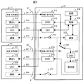
図1は、第1の実施例を示す説明図であって、映像源11及び12が、表示機器21とHDMIケーブル31及び32を介して接続されている。映像源11と12は、それぞれ映像・音声送信部111と121、読出し部112と122、CEC通信部113と123、通信部114と115から構成されるHDMI出力を一つずつ有する。映像源11、12は、例えばHDDレコーダや、STBなどである。
FIG. 1 is an explanatory diagram showing the first embodiment, in which
なお、映像源と表示機器とを総称して映像機器とも表現する。また、表示機器21は表示部を含む構成としているが、必ずしも表示部を含む必要は無く、表示部の代わりに他の表示装置に映像信号を出力する出力部を有する構成としてもよい。
The video source and the display device are collectively referred to as a video device. The
表示機器21は、HDMI入力1と2とを有する。そして、HDMI入力1と2とはそれぞれ映像・音声受信部211と215、EDID部212と216、スイッチ214と217を有し、CEC通信部213はHDMI入力1と2とで共用している。
The
複数のHDMI入力で共用する機能ブロック(以下、「共通インタフェース機能ブロック」とも言う。)として、通信部220を有し、スイッチ214とスイッチ217で複数あるHDMI入力のいずれかにこれらの機能を提供するかを切換える。218は設定記憶部、219は制御部、221は映像・音声の切換スイッチ、222はOSD(On Screen Display)部、223は表示部である。
As a functional block shared by a plurality of HDMI inputs (hereinafter also referred to as “common interface functional block”), the
HDMIケーブル31と32はそれぞれ映像・音声データを伝送するTMDS(Transition Minimized Differential Signaling)ライン311と321、EDIDデータを伝送するDDC(Display Data Channel)ライン313と323、信号線314と324で構成される。
The
まず、高速双方向伝送を例にとって説明する。表示機器21は複数のHDMI入力を有するが、高速双方向伝送を実現する通信部220は1個である。図1の例では、スイッチ214が接続されているので、HDMIケーブル31が接続されるHDMI入力において高速双方向通信が可能となる。高速双方向通信が可能であることを、HDMIの受信能力を伝達するEDID212に登録し、相手の映像源11へ伝える。なお、EDID部は機能伝達部又は能力伝達部、CEC通信部は制御信号送受信部、OSD部は画像合成部ともいう。
First, a description will be given taking high-speed bidirectional transmission as an example. The
一方、通信部220は同時に複数の相手への通信できない場合、スイッチ217を非接続とし、現在高速双方向通信が不可能であることをEDID216に登録し、相手の映像源12へ伝える。これによって、映像源12は、通信部124の機能を休止させる。
On the other hand, when the
なお、スイッチ214とスイッチ217の接続が入れ替わった場合、すなわちスイッチ214が非接続、スイッチ217が接続の状態になった場合は、高速双方向通信が不可能となったことをEDID212に、高速双方向通信が可能となったことをEDID216に再度登録する。
Note that when the connection between the
このように、共通インタフェース機能ブロックとしての通信部220とHDMI入力部間をスイッチで切換え、受信能力を伝達するEDIDに通信部220の利用の可否、すなわち高速双方向通信が可能であるか否かを登録することにより、HDMI入力1と2で高速双方向伝送機能を切換えて利用することができる。これにより高速双方向通信を実現する表示機器の通信部を複数設ける必要が無くるため、回路構成を簡素化でき、合理化できる効果がある。
In this way, the
なお、この切換えは、ユーザが表示機器21のOSD部222が出力する設定メニューを見て設定してもよいし、先着順で切換えてもよい。また、HDMI入力、表示機器の通信部の個数は上記に限定されず、HDMI入力の数よりも表示機器の通信部の数が少ない場合には、上述と同様にスイッチを用いて表示機器の通信部とHDMI入力との接続、非接続を切換えることで、高速双方向伝送機能を切換えて利用することができる。これにより、HDMI入力の数よりも表示機器の通信部の数を減らすことができ、回路構成の簡素化、合理化が可能となる。
This switching may be set by the user looking at the setting menu output from the OSD unit 222 of the
HDMI入力1に高速双方向伝送機能を割当てた場合は、その旨をユーザに通知するよう制御部219が表示機器21を制御する。例えば、図5に示すメッセージ表示をOSD部222で合成してユーザに伝えるように制御したり、表示機器21に高速双方向伝送機能の割当を示すLED等の発光部を設け、当該発光部の発光を制御したりすればよい。
When the high-speed bidirectional transmission function is assigned to the HDMI input 1, the control unit 219 controls the
また、高速双方向伝送機能をHDMI入力2に割当て変更した場合は、例えば図6に示すメッセージをOSD部222で合成してユーザに伝えるよう制御してもよい。さらに、HDMI入力が複数ある場合は、図7のように、一覧表示させてもよい。
When the high-speed bidirectional transmission function is changed to the
次に表示機器の通信部220とHDMI入力との接続の切換えについて、先着順で切換える方式を、図2のフローチャートを用いて説明する。図2において、EDID−1は図1のEDID部212の登録内容、EDID−2は図1のEDID部216の登録内容を示す。HPD-1とHPD-2は、図1では図示していないが、HDMI仕様で定義されているEDID読出し可否を示すHPD(Hot Plug Detect)信号に相当する。HPD−1=“H”でEDID-1の読出し可、HPD−1=“L”でEDID−1の読出し不可を示す信号である。
Next, a method of switching the connection between the
初期状態501において、HPD−1とHPD−2はいずれも“H”(EDID読出し可能状態)でEDID−1とEDID−2共に、通信機能ありを示している。ここで、入力1の通信が始まると、状態502に移行する。
In the
HPD−2=“L“(EDID−2読出し不可)としてEDID−2の状態を通信機能なしに変更後、HPD−2=”H”(EDID−2読出し可)へ設定し、接続先の映像源12へ伝える。入力1の通信が終了すると、状態503へ移行する。HPD−2=“L“(EDID−2読出し不可)としてEDID−2の状態を通信機能ありに変更後、HPD−2=”H”(EDID−2読出し可)へ設定し、初期状態501と同じ状態になる。
After changing the EDID-2 state without communication function as HPD-2 = “L” (EDID-2 cannot be read), set to HPD-2 = “H” (EDID-2 can be read). Tell the source 12. When the communication of input 1 is completed, the state shifts to
受信能力の伝達について、CECを使った第2の実施例を、図3のフローチャートを用いて説明する。初期状態511において、図1の記憶部218に、入力1と2共に通信機能待機状態と登録し、スイッチ214とスイッチ217を非接続状態とする。
A second embodiment using CEC will be described with reference to the flowchart of FIG. In the
CECで入力1の通信要求がくると、状態512へ移行する。入力1の通信開始と入力2の通信停止を記憶部218へ登録し、スイッチ214を接続して通信を開始する。CECで入力2の通信要求が来ると、状態513に示すように、入力端子2に通信機能が無いことをCECで返答し、状態512へ戻る。
When a communication request of input 1 is received by CEC, the state shifts to
さらに、CECで入力1の通信終了指示があるか、入力1の通信が終了した場合は、初期状態511へ移行する。どの状態にあるかは、記憶部218の設定を参照すればわかる。このようにすることで、ユーザの手をわずらわせることなく、自動的に共通インタフェース機能ブロックの機能の設定変更ができる。
Further, when there is an instruction to end communication of input 1 in CEC or when communication of input 1 is ended, the process shifts to an
次に、映像源11が映像源兼オーディオアンプであることを想定し、音声信号伝送を例にとって第3の実施例を説明する。表示機器21が映像源12を選択して、TMDSライン321から映像・音声信号を受けている場合、表示機器21は映像源12から来る映像信号を表示できるが、映像源12から来る音声信号をオーディオアンプである映像源11へ伝送する仕組みが無いと、オーディオアンプでの高音質再生ができない。これは、TMDSライン311は、オーディオアンプである映像源11から表示機器21へ映像・音声伝送を行えるが、逆の伝送が出来ないからである。表示機器か21からオーディアオアンプである映像源への音声伝送のこの新たな仕組みとして、通信部114と220を使うことが考えられる。
Next, assuming that the
この場合、CECの仕組みから、映像源11と映像源12のどちらがオーディオアンプであるかは、映像機器の種別を示すCECの論理アドレスを見れば容易に判明する。この動作を図4のフローチャートを用いて説明する。
In this case, the CEC mechanism makes it easy to determine which of the
初期状態521において、音声伝送機能をHDMI入力1に割当てることを記憶部に記憶させ、通信部220とHDMI入力1の間にあるスイッチ214を接続状態、他のHDMI入力2につながるスイッチ217は非接続状態としておく。
In the
次にCECの仕組みからHDMI入力1に検出された機器がオーディオアンプである場合は、初期状態521を継続する。
Next, when the device detected as HDMI input 1 from the CEC mechanism is an audio amplifier, the
ここで、オーディオアンプがHDMI入力2に検出された場合は、状態522へ移行し、音声伝送機能の割当を入力1から入力2に変更することを記憶部に記憶させ、通信部220とHDMI入力1の間にあるスイッチ214を非接続状態、HDMI入力2につながるスイッチ217を接続状態として、音声伝送機能をHDMI入力2に割当てる。
Here, when the audio amplifier is detected at the
このように、オーディオアンプを示す論理アドレスを持つ映像源が検出されたHDMI入力2へ、音声伝送を実現する通信部220を割当てることによって、ユーザの手をわずらわす設定変更無しに、自動切換えを実現できる。
As described above, the
先の例では、オーディオアンプの論理アドレスを検出して用いる例を示したが、オーディオアンプから音声信号を要求された時に、割当ての自動切換えを行うようにしてもよい。この場合、前方スピーカ接続アンプと後方スピーカ接続アンプのように、複数のオーディオアンプがつながれているときに、複数のアンプへ同じ音声信号を流すことが許される場合は、スイッチ214と217を同時に接続状態として使ってもよい。同じ音声信号を許容されるかどうかは、複数のアンプに対してCECによる受信能力確認を行うことによって表示機器が判断できる。 In the previous example, an example in which the logical address of the audio amplifier is detected and used has been described. However, when an audio signal is requested from the audio amplifier, automatic allocation switching may be performed. In this case, when a plurality of audio amplifiers are connected, such as a front speaker connection amplifier and a rear speaker connection amplifier, when the same audio signal is allowed to flow to the plurality of amplifiers, switches 214 and 217 are connected simultaneously. It may be used as a state. Whether or not the same audio signal is allowed can be determined by the display device by confirming the reception capability by CEC for a plurality of amplifiers.
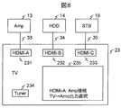
次に、第4の実施例を図8と図9の映像機器の接続形態例を用いて説明する。23はTVで、HDMI入力231、232、233、放送を受信するチューナ234、表示部235で構成されている。13はオーディオアンプ、14はHDDレコーダ、15はSTB、33〜35はHDMIケーブルである。
Next, a fourth embodiment will be described with reference to examples of connection forms of video equipment shown in FIGS.
TV23は、HDMI入力から音声信号を接続された映像機器へ出力する機能を有し、必要とするHDMI入力へその機能を順次割当てるもので、例えば、第3の実施例で示した表示機器21である。TV23のHDMI-A入力231に、オーディオアンプが接続されていることを検出したTV23は、HDMI−A入力231に音声出力機能を割当て、割当てた結果を表示部235に表示してユーザへ知らせるように制御する。
The
ここで、図9に示すように、オーディオアンプ13とHDDレコーダ14のHDMI接続ケーブル33と34とを入れ替えると、TV23はその入れ替えを検出し、HDMI−B入力232に音声出力機能を割当てなおし、割当てた結果を表示部235に表示してユーザへ知らせるように制御する。HDMI接続ケーブル33と34と入れ替えは、例えば映像源から表示機器へ与えられるEDID読出し回路用の電源DDC+5Vが、ケーブル入換え時に途絶えることを認識し、その途絶えた端子に接続された機器の種類を接続相手機器に問い合わせるようにして検出すればよい。
Here, as shown in FIG. 9, when the
次に、第5の実施例を、図10を用いて説明する。図10は映像機器のHDMI入力部分の配置図である。先に説明した実施例では、複数のHDMI入力で当該入力よりも少ない数の機能ブロックを共有する場合に、どのHDMI入力に共通インタフェース機能ブロックが割り当てられているかは映像表示を行う画面上にOSD表示させたものであった。 Next, a fifth embodiment will be described with reference to FIG. FIG. 10 is a layout diagram of the HDMI input portion of the video equipment. In the embodiment described above, when a plurality of HDMI inputs share a smaller number of functional blocks than the input, which HDMI input is assigned with the common interface functional block is determined by the OSD on the screen for video display. It was what was displayed.
これに対して本実施例では、図10に示すように、その表示をHDMI入力コネクタの近傍に配置されたLEDを光らせて、どのコネクタに共通インタフェース機能ブロックの機能が割当てられているかを表示させるものである。 On the other hand, in the present embodiment, as shown in FIG. 10, an LED arranged in the vicinity of the HDMI input connector is illuminated to display which connector is assigned the function of the common interface function block. Is.
さらに、このLEDは動作状態に合わせて、例えば機能割当ての有無を点灯/非点灯や色変化で、また機能割当て時の通信速度を点滅速度や輝度で表現して、その動作状態をユーザに知らせ、ユーザがその動作を確認できるようにしてもよい。 Furthermore, according to the operating state, this LED indicates whether the function is assigned, for example, whether it is lit / not lit or a color change, and the communication speed at the time of function assignment is expressed by a blinking speed or brightness to inform the user of the operating state. The user may be able to confirm the operation.
この表示により、ユーザへ安心感を与えるメリットがある。尚、表示はLEDでなくても、LCDやEL、電子ペーパーなどの表示デバイスであってもよい。また、HDMI入力コネクタが装置の背面に設置されている場合、通常の使用状態でユーザからは見えない状態であることが考えられる。このような場合は、共通インタフェース機能ブロックの割当を装置前面にLEDを設けて表示したり、装置前面のLCD等の表示部に表示したりしてもよい。 This display has the merit of giving the user a sense of security. The display may not be an LED, but may be a display device such as an LCD, EL, or electronic paper. In addition, when the HDMI input connector is installed on the back of the apparatus, it is considered that the user cannot see the HDMI input connector in a normal use state. In such a case, the assignment of the common interface function block may be displayed by providing an LED on the front side of the apparatus, or may be displayed on a display unit such as an LCD on the front side of the apparatus.
図11は、第6の実施例を示す説明図である。第1の実施例を説明した図1では、表示機器21がHDMI入力1と2を有していたが、図11では、STB16がHDMI入力1とHDMI出力3を持つ場合を説明している。図1と同機能のものは同じ番号を付しており、説明を省略する。
FIG. 11 is an explanatory diagram showing the sixth embodiment. In FIG. 1 for explaining the first embodiment, the
映像源11とTVなどの映像受信機26が、STB16とHDMIケーブル31と33で接続されている。映像受信機26は、映像・音声受信部261と、EDID部262、CEC通信部263、通信部26から構成され、HDMIケーブル33からの映像・音声出力を受信する機能を持っている。HDMIケーブル33は、TMDSライン331と、DDCライン332、CECライン333、信号線334から構成されている。
A
STB16は、映像・音声受信部211とEDID部212、CEC通信部213、スイッチ214と167、記憶部168、制御部169、通信部170、切換えスイッチ171、チューナ172から構成されている。STB16は、HDMI入力1に入力された映像源11の映像・音声出力と、内蔵するチューナ172の映像・音声出力を、スイッチ171で切換えて、HDMI出力3から映像受信機26へ伝送する機能を持っている。
The
共通インタフェース機能ブロックである通信部170が双方向高速通信を提供する場合を例にとって、以下、説明する。
The case where the
STB16が映像受信機26と高速双方向通信を必要とする場合、スイッチ167を接続状態、スイッチ214を非接続状態として、通信部170と通信部264の間で通信を開始すればよい。通信前に何らかの初期設定が必要な場合は、CECライン333を経由してCEC通信部213とCEC通信部263が初期設定情報をあらかじめ交換してもよい。
When the
また、映像受信機器26がSTB16と高速双方向通信を要求する場合は、CECライン333経由でCEC通信部263からCEC通信部213へ要求メッセージを出してもよいし、信号線334へ要求信号を流してもよい。
When the
信号線334へ通信要求信号を流す場合は、STB16内に通信要求信号を受信できる回路(図示せず)を用意する必要があるが、高速双方向通信を実現する回路規模に比べれば小規模であり、共通インタフェース機能ブロックを設けて合理化する効果の方が大きい。
When sending a communication request signal to the signal line 334, it is necessary to prepare a circuit (not shown) capable of receiving the communication request signal in the
通信部170を映像受信機26との通信に割当てた場合、制御部169は記憶部168にその割当て情報を登録する。この時、映像源11から通信要求がCECライン313やHDMIケーブル31内のその他の信号線から来た場合は、それを拒否する応答を行う。但し、通信部170が映像受信機26との通信に割当てられていても、実際の通信が行われていない場合、映像受信機26へ通知又は、問い合わせして許可を得て通信部170の割当先を変更するかは、STB16の制御部169が判断して行えばよい。
When the
以上、共通インタフェース機能ブロックを1個持つ場合を例にとり、説明してきたが、インタフェース数より少ない複数の共通インタフェース機能を持ってもよいし、複数種類の共通インタフェース機能ブロックを用意してもよい。また、スイッチ214,127,167の接続/非接続は、信号伝達の有無を制御するものであってもよい。
As described above, the case of having one common interface function block has been described as an example. However, a plurality of common interface functions less than the number of interfaces may be provided, or a plurality of types of common interface function blocks may be prepared. Further, the connection / disconnection of the
以上、述べてきたように、共通インタフェース機能ブロックを、複数のHDMIなどのインタフェースに適宜割当てることにより、全インタフェースで同時使用することが無い機能ブロックを全インタフェースに持たせる必要が無いので、構成が簡単かつ低コストで実現できる利点がある。さらに、自動的に割当てる仕組みにより、ユーザの手を煩わせることなく、操作ミスの少ない動作環境を提供できる利点がある。 As described above, the common interface functional block is appropriately assigned to a plurality of interfaces such as HDMI, so that it is not necessary to provide all the interfaces with functional blocks that are not used simultaneously on all interfaces. There is an advantage that can be realized easily and at low cost. Furthermore, the automatic assignment mechanism has an advantage that an operation environment with few operation errors can be provided without bothering the user.
また、上記実施例では共通インタフェース機能ブロックとして高速双方向通信を実現する通信部を例に説明しているが、その他の機能を実現する機能ブロックであってもよい。 In the above-described embodiment, the communication unit that realizes high-speed bidirectional communication is described as an example of the common interface function block. However, the function block that realizes other functions may be used.
1,2,231,232,233 HDMI入力、 3 HDMI出力、 11,12 映像源、 16 STB、 111,121,165 映像・音声送信部、 112,122,168 EDID読出し部、 113,123,213,263 CEC通信部、 114,124,170,220,264 通信部、 21 TV、 26 映像受信機、 211,215,261 映像・音声受信部、 212,216,262 EDID部、 167,214,217 スイッチ、 168,218 記憶部、 169,219 制御部、 171,221 切換スイッチ、 222 OSD部、 223 表示部、 31,32,33 HDMIケーブル、 311,321,331 TMDSライン、 312,322,332 DDCライン、 313,323,333 CECライン、 314,324,334 信号線、 501,511 初期状態、 502,512 通信設定状態、 503,513 通信解除状態、 13 オーディオアンプ、 14 HDDレコーダ、 15 STB、 23 TV、 172,234 チューナ、 235 表示画面、 241,242,243 HDMIレセプタクル、 251,252,253 LED 1, 2, 231, 232, 233 HDMI input, 3 HDMI output, 11, 12 video source, 16 STB, 111, 121, 165 video / audio transmission unit, 112, 122, 168 EDID reading unit, 113, 123, 213 , 263 CEC communication unit, 114, 124, 170, 220, 264 communication unit, 21 TV, 26 video receiver, 211, 215, 261 video / audio reception unit, 212, 216, 262 EDID unit, 167, 214, 217 Switch, 168, 218 storage unit, 169, 219 control unit, 171, 221 selector switch, 222 OSD unit, 223 display unit, 31, 32, 33 HDMI cable, 311, 321, 331 TMDS line, 312, 322, 332 DDC Line, 313 23,333 CEC line, 314,324,334 signal line, 501,511 initial state, 502,512 communication setting state, 503,513 communication release state, 13 audio amplifier, 14 HDD recorder, 15 STB, 23 TV, 172 234 tuner, 235 display screen, 241, 242, 243 HDMI receptacle, 251, 252, 253 LED
Claims (10)
前記複数のインタフェースに接続され、接続されたインタフェースに所定の機能を提供する機能ブロックと、を備え、
前記複数のインタフェースのいずれかのインタフェースにおいて前記機能ブロックが提供する機能の使用が開始されると、当該インタフェース以外のインタフェースと前記機能ブロックとの信号伝達を切断し、
前記機能ブロックが提供する機能の使用が開始されたインタフェース以外のインタフェースにおける前記機能ブロックが提供する機能の使用要求を受信すると、前記機能ブロックが提供する機能が使用不可能であることを伝達する映像機器。 Image, a plurality of interfaces for receiving signals including audio signals,
Connected to said plurality of interfaces, and a function block providing a predetermined function to the connected interface,
When the use of the function provided by the functional block is started in any one of the plurality of interfaces, the signal transmission between the interface other than the interface and the functional block is disconnected,
When a use request for the function provided by the function block in an interface other than the interface where the use of the function provided by the function block is started is received, a video that conveys that the function provided by the function block cannot be used. machine.
映像、音声信号を含む信号を受信する第2のインタフェースと、
前記第1のインタフェース又は前記第2のインタフェースに接続され、接続されたインタフェースに所定の機能を提供する機能ブロックと、
を備え、
前記第1のインタフェースにおいて前記機能ブロックが提供する機能の使用が開始されると、前記第2のインタフェースと前記機能ブロックとの信号伝達を切断し、前記第2のインタフェースにおける前記機能ブロックが提供する機能の使用要求を受信すると、前記機能ブロックが提供する機能が使用不可能であることを伝達する映像機器。 Image, a first interface for receiving a signal including a speech signal,
Image, a second interface for receiving a signal including a speech signal,
A functional block connected to the first interface or the second interface and providing a predetermined function to the connected interface ;
With
When the use of the function provided by the functional block is started in the first interface, the signal transmission between the second interface and the functional block is cut off, and the functional block in the second interface provides When receiving a function use request, the video equipment transmits that the function provided by the function block cannot be used .
インタフェースの機能を伝達する機能伝達部を備え、
前記インタフェースはHDMIであり、
前記機能伝達部がEDIDを用いて前記インタフェースの機能を伝達する映像機器。 The video equipment according to claim 1 or 2,
It has a function transmission part that transmits the function of the interface,
The interface is HDMI,
Video apparatus the function transferring section to transfer the functions of the interface with the EDID.
インタフェースを介して接続された他の機器との間で制御信号を送受信する制御信号送受信部を有し、
前記インタフェースはHDMIであり、
前記制御信号送受信部がCECラインを介して前記インタフェースの機能を伝達する映像機器。 The video equipment according to claim 1 or 2,
A control signal transmission / reception unit for transmitting / receiving a control signal to / from another device connected via the interface;
The interface is HDMI,
Video apparatus wherein the control signal transmission and reception unit transmits the functions of the interface via the CEC line.
インタフェースで受信した映像信号に所定の表示を合成する画像合成部を有し、
前記所定の表示は、前記機能ブロックの機能が提供されたインタフェースの表示である映像機器。 The video equipment according to any one of claims 1 to 4 ,
And an image synthesizing unit for synthesizing the predetermined display on the video signal received by interface,
The predetermined display is video equipment which is a display of an interface provided with the function of the functional block.
前記機能ブロックの機能が提供されたインタフェースを表示する表示部を有する映像機器。 The video equipment according to any one of claims 1 to 4,
A video device having a display unit for displaying an interface provided with the function of the functional block.
前記複数のインタフェースに接続され、接続されたインタフェースに所定の機能を提供する機能ブロックと、
制御信号を送受信する制御信号送受信部と、
前記制御信号送受信部で受信する制御信号から前記複数のインタフェースのいずれかのインタフェースに接続された機器の種類を判別し、接続された機器が前記機能ブロックの提供する機能を利用可能であった場合に、当該インタフェースと前記機能ブロックとを接続するように制御する制御部と、を有する映像機器。 Image, a plurality of interfaces for receiving signals including audio signals,
A functional block connected to the plurality of interfaces and providing a predetermined function to the connected interfaces;
A control signal transmitting and receiving unit for transmitting and receiving control signals;
When the type of device connected to any one of the plurality of interfaces is determined from the control signal received by the control signal transmission / reception unit, and the function provided by the functional block can be used by the connected device , the video apparatus and a control unit for controlling so as to connect the with the interface the functional block.
前記複数のインタフェースの機能を当該インタフェースに接続された機器に伝達する機能伝達部を有し、
前記機能伝達部は前記機能ブロックの機能を有するインタフェースに接続された機器に当該機能を伝達する映像機器。 The video equipment according to claim 7,
A function transmission unit that transmits the functions of the plurality of interfaces to a device connected to the interface;
The function transmitting unit is a video device that transmits the function to a device connected to an interface having the function of the function block.
前記複数のインタフェースはHDMIであり、
前記制御信号送受信部で送受信する信号はCECである映像機器。 The video equipment according to claim 7 or 8,
The plurality of interfaces are HDMI;
A video device in which a signal transmitted and received by the control signal transmitting and receiving unit is CEC.
前記複数のインタフェースはHDMIであり、
前記機能伝達部はEDIDを用いて機能を伝達する映像機器。 The video equipment according to claim 8,
The plurality of interfaces are HDMI;
The function transmission unit is a video device that transmits functions using EDID.
Priority Applications (4)
| Application Number | Priority Date | Filing Date | Title |
|---|---|---|---|
| JP2009104646A JP5645370B2 (en) | 2009-04-23 | 2009-04-23 | Video equipment |
| EP10250808A EP2244247A3 (en) | 2009-04-23 | 2010-04-21 | Video apparatus |
| US12/765,227 US8370539B2 (en) | 2009-04-23 | 2010-04-22 | Video apparatus |
| CN201010167330.1A CN101873461B (en) | 2009-04-23 | 2010-04-23 | Image documentation equipment |
Applications Claiming Priority (1)
| Application Number | Priority Date | Filing Date | Title |
|---|---|---|---|
| JP2009104646A JP5645370B2 (en) | 2009-04-23 | 2009-04-23 | Video equipment |
Publications (3)
| Publication Number | Publication Date |
|---|---|
| JP2010258633A JP2010258633A (en) | 2010-11-11 |
| JP2010258633A5 JP2010258633A5 (en) | 2011-11-10 |
| JP5645370B2 true JP5645370B2 (en) | 2014-12-24 |
Family
ID=42272522
Family Applications (1)
| Application Number | Title | Priority Date | Filing Date |
|---|---|---|---|
| JP2009104646A Active JP5645370B2 (en) | 2009-04-23 | 2009-04-23 | Video equipment |
Country Status (4)
| Country | Link |
|---|---|
| US (1) | US8370539B2 (en) |
| EP (1) | EP2244247A3 (en) |
| JP (1) | JP5645370B2 (en) |
| CN (1) | CN101873461B (en) |
Families Citing this family (5)
| Publication number | Priority date | Publication date | Assignee | Title |
|---|---|---|---|---|
| US20100115140A1 (en) * | 2008-10-30 | 2010-05-06 | Micron Technology, Inc. | Encoded addressing within control code for bus communication |
| JP5645370B2 (en) * | 2009-04-23 | 2014-12-24 | 日立マクセル株式会社 | Video equipment |
| JP5573361B2 (en) | 2010-05-25 | 2014-08-20 | ソニー株式会社 | Transmission device, reception device, transmission method, reception method, and transmission / reception device |
| US8681977B2 (en) * | 2011-12-13 | 2014-03-25 | Crestron Electronics Inc. | Enabling/disabling display data channel access to enable/ disable high-bandwidth digital content protection |
| US8713316B2 (en) * | 2011-12-13 | 2014-04-29 | Crestron Electronics Inc. | System, apparatus and method for enabling/disabling display data channel access to enable/disable high-bandwidth digital content protection |
Family Cites Families (16)
| Publication number | Priority date | Publication date | Assignee | Title |
|---|---|---|---|---|
| DE10123507A1 (en) * | 2001-05-15 | 2002-11-21 | Siemens Ag | Package for transporting coil springs for throttle valves comprises tubular sleeve in which springs are fitted after threading on to rod, springs being held on rods by pins passing through it |
| JP4037630B2 (en) * | 2001-09-06 | 2008-01-23 | 株式会社東芝 | Digital AV apparatus and control method thereof |
| JP4431308B2 (en) | 2002-03-29 | 2010-03-10 | 株式会社日立製作所 | Audio processing device, audio processing system, audio output device, and video display device |
| US20030185400A1 (en) | 2002-03-29 | 2003-10-02 | Hitachi, Ltd. | Sound processing unit, sound processing system, audio output unit and display device |
| JP2006019948A (en) * | 2004-06-30 | 2006-01-19 | Toshiba Corp | Video signal output device |
| JP2006229689A (en) * | 2005-02-18 | 2006-08-31 | Canon Inc | Image processor |
| EP2071849A4 (en) * | 2006-11-07 | 2010-08-04 | Sony Corp | Receiver, delayed information transmitting method for receivers, audio output device, and delay control method for audio output devices |
| JP4289397B2 (en) * | 2007-01-04 | 2009-07-01 | 船井電機株式会社 | Receiver |
| JP5029121B2 (en) * | 2007-04-25 | 2012-09-19 | ソニー株式会社 | Data receiving apparatus, data transmitting apparatus, information processing method, and computer program |
| JP2009003882A (en) * | 2007-06-25 | 2009-01-08 | Toshiba Corp | Data receiver and data transmitting/receiving method |
| JP5240491B2 (en) | 2007-06-26 | 2013-07-17 | ソニー株式会社 | Transmitter and receiver |
| JP5150158B2 (en) | 2007-07-31 | 2013-02-20 | 株式会社東芝 | Television receiver and television display method |
| KR101402680B1 (en) * | 2007-10-09 | 2014-06-09 | 삼성전자 주식회사 | Image display device and method for changing EDID information thereof |
| JP5337370B2 (en) * | 2007-11-13 | 2013-11-06 | ソニー エスパナ,エス.エー. | Display device, video signal transmission method in display device, transmission device, and video signal transmission method |
| JP2009253468A (en) * | 2008-04-02 | 2009-10-29 | Canon Inc | Video controller and method of controlling the same |
| JP5645370B2 (en) * | 2009-04-23 | 2014-12-24 | 日立マクセル株式会社 | Video equipment |
-
2009
- 2009-04-23 JP JP2009104646A patent/JP5645370B2/en active Active
-
2010
- 2010-04-21 EP EP10250808A patent/EP2244247A3/en not_active Ceased
- 2010-04-22 US US12/765,227 patent/US8370539B2/en active Active
- 2010-04-23 CN CN201010167330.1A patent/CN101873461B/en active Active
Also Published As
| Publication number | Publication date |
|---|---|
| CN101873461B (en) | 2016-06-22 |
| JP2010258633A (en) | 2010-11-11 |
| EP2244247A2 (en) | 2010-10-27 |
| EP2244247A3 (en) | 2013-01-16 |
| CN101873461A (en) | 2010-10-27 |
| US20100271548A1 (en) | 2010-10-28 |
| US8370539B2 (en) | 2013-02-05 |
Similar Documents
| Publication | Publication Date | Title |
|---|---|---|
| JP4251460B2 (en) | Display system and display device | |
| US8042145B2 (en) | Method of controlling power states in a multimedia system | |
| JP5013527B2 (en) | AV system and display device | |
| JP4844230B2 (en) | COMMUNICATION SYSTEM, TRANSMISSION DEVICE AND RECEPTION DEVICE, COMMUNICATION METHOD, AND PROGRAM | |
| US20090284536A1 (en) | Display apparatus and display system | |
| JP2008067024A (en) | Display device and display system | |
| CN108293149B (en) | Image display device | |
| JP5645370B2 (en) | Video equipment | |
| JP2008160653A (en) | Data receiver | |
| JP4762075B2 (en) | Display device and display system | |
| JP2009141537A (en) | Display system, display device and repeater apparatus | |
| JP4917452B2 (en) | Display device and display system | |
| JP5273375B2 (en) | Video system and menu screen display control method | |
| EP2536128A1 (en) | Content reproducing device and content reproduction control method | |
| JP2009294797A (en) | Communication device, conversion adapter, and method of controlling communication device | |
| JP4799337B2 (en) | Display device, AV device, and display system including these | |
| JP2008145679A (en) | Display apparatus and av system | |
| US8229272B2 (en) | Video apparatus capable of changing video output mode of external video apparatus according to video input mode of the video apparatus and control method thereof | |
| JP4889610B2 (en) | Display device and display system | |
| JP4666384B2 (en) | Recording reservation system | |
| KR20130051711A (en) | Mobile high-definition link apparatus and method for exchange modes in mobile high-definition link apparatus | |
| JP2011004067A (en) | Digital av apparatus, tool for copying setting data, and method for copying setting data | |
| JP5698945B2 (en) | Display device and signal processing method | |
| WO2014068630A1 (en) | Repeater and transmission/reception method | |
| JP5692990B2 (en) | Wireless communication device |
Legal Events
| Date | Code | Title | Description |
|---|---|---|---|
| A521 | Request for written amendment filed |
Free format text: JAPANESE INTERMEDIATE CODE: A523 Effective date: 20110927 |
|
| A621 | Written request for application examination |
Free format text: JAPANESE INTERMEDIATE CODE: A621 Effective date: 20110927 |
|
| A977 | Report on retrieval |
Free format text: JAPANESE INTERMEDIATE CODE: A971007 Effective date: 20121107 |
|
| A131 | Notification of reasons for refusal |
Free format text: JAPANESE INTERMEDIATE CODE: A131 Effective date: 20121211 |
|
| A521 | Request for written amendment filed |
Free format text: JAPANESE INTERMEDIATE CODE: A523 Effective date: 20130212 |
|
| A711 | Notification of change in applicant |
Free format text: JAPANESE INTERMEDIATE CODE: A712 Effective date: 20130529 |
|
| A02 | Decision of refusal |
Free format text: JAPANESE INTERMEDIATE CODE: A02 Effective date: 20130827 |
|
| A521 | Request for written amendment filed |
Free format text: JAPANESE INTERMEDIATE CODE: A523 Effective date: 20131125 |
|
| RD02 | Notification of acceptance of power of attorney |
Free format text: JAPANESE INTERMEDIATE CODE: A7422 Effective date: 20140311 |
|
| RD04 | Notification of resignation of power of attorney |
Free format text: JAPANESE INTERMEDIATE CODE: A7424 Effective date: 20140319 |
|
| A711 | Notification of change in applicant |
Free format text: JAPANESE INTERMEDIATE CODE: A712 Effective date: 20140908 |
|
| A61 | First payment of annual fees (during grant procedure) |
Free format text: JAPANESE INTERMEDIATE CODE: A61 Effective date: 20141104 |
|
| R150 | Certificate of patent or registration of utility model |
Ref document number: 5645370 Country of ref document: JP Free format text: JAPANESE INTERMEDIATE CODE: R150 |
|
| R250 | Receipt of annual fees |
Free format text: JAPANESE INTERMEDIATE CODE: R250 |
|
| S111 | Request for change of ownership or part of ownership |
Free format text: JAPANESE INTERMEDIATE CODE: R313111 |
|
| R350 | Written notification of registration of transfer |
Free format text: JAPANESE INTERMEDIATE CODE: R350 |
|
| R250 | Receipt of annual fees |
Free format text: JAPANESE INTERMEDIATE CODE: R250 |
|
| R250 | Receipt of annual fees |
Free format text: JAPANESE INTERMEDIATE CODE: R250 |
|
| R250 | Receipt of annual fees |
Free format text: JAPANESE INTERMEDIATE CODE: R250 |
|
| R250 | Receipt of annual fees |
Free format text: JAPANESE INTERMEDIATE CODE: R250 |
|
| S111 | Request for change of ownership or part of ownership |
Free format text: JAPANESE INTERMEDIATE CODE: R313111 |
|
| R350 | Written notification of registration of transfer |
Free format text: JAPANESE INTERMEDIATE CODE: R350 |
|
| R250 | Receipt of annual fees |
Free format text: JAPANESE INTERMEDIATE CODE: R250 |
|
| R250 | Receipt of annual fees |
Free format text: JAPANESE INTERMEDIATE CODE: R250 |