JP4526552B2 - Stove device - Google Patents
Stove device Download PDFInfo
- Publication number
- JP4526552B2 JP4526552B2 JP2007152545A JP2007152545A JP4526552B2 JP 4526552 B2 JP4526552 B2 JP 4526552B2 JP 2007152545 A JP2007152545 A JP 2007152545A JP 2007152545 A JP2007152545 A JP 2007152545A JP 4526552 B2 JP4526552 B2 JP 4526552B2
- Authority
- JP
- Japan
- Prior art keywords
- top plate
- grill
- image
- screen
- unit
- Prior art date
- Legal status (The legal status is an assumption and is not a legal conclusion. Google has not performed a legal analysis and makes no representation as to the accuracy of the status listed.)
- Expired - Fee Related
Links
Images

Landscapes
- Projection Apparatus (AREA)
- Transforming Electric Information Into Light Information (AREA)
Description
本発明は、天板にガラスなどの透光性を備えたものを有するコンロ装置に関する。 The present invention relates to a stove apparatus having a top plate provided with translucency such as glass.
台所にテレビ画像を表示することのできる画像表示部を設け、コンロ装置を用いて調理する場合、調理中にレシピやテレビ映像を画像表示部に表示されるものが知られている(例えば、特許文献1参照)。 When an image display unit capable of displaying a TV image is provided in a kitchen and cooking is performed using a stove device, a recipe or a TV image is displayed on the image display unit during cooking (for example, a patent is known) Reference 1).
また、この特許文献1に記載されたものの他にも小型のテレビを台所においてテレビ画像を見ながら調理することや、ポータブルのゲーム機に調理レシピを表示すると共に解説をそのゲーム機から発音させ、表示されたレシピを見ながら、かつ解説を聞きながら調理するようにしたものも知られている。
コンロ装置を用いた調理中に、上記従来のテレビ装置やゲーム機に表示された画像を見る場合、テレビ装置やゲーム機はコンロ装置の側方、もしくは離れた位置に置く場合があり、いずれにせよ、画像を見る場合には調理中の鍋などから大きく視線を左右に外す必要が生じる。 During cooking using a stove device, when viewing the image displayed on the conventional television device or game machine, the TV device or game machine may be placed on the side of the stove device or at a remote position. Anyway, when viewing an image, it is necessary to remove the line of sight from the cooking pot or the like to the left or right.
また、コンロ装置の周辺に他の調理器具などが置かれている場合には、ゲーム機をセットすることができず、仮にセットできたとしても、調理中の油跳ね等でゲーム機が汚れるという不具合が生じる。さらには上記特許文献1に記載されたものでは、テレビ装置を台所の壁に収納させるため、大幅な工事を行う必要が生じる。 In addition, when other cooking utensils are placed around the stove device, the game machine cannot be set, and even if it can be set, the game machine gets dirty due to oil splashing during cooking, etc. A malfunction occurs. Furthermore, in what was described in the said patent document 1, in order to accommodate a television apparatus in the wall of a kitchen, it will be necessary to perform a big construction.
そこで本発明は、上記の問題点に鑑み、上記の種々の不具合が生じないコンロ装置を提供することを課題とする。 Then, this invention makes it a subject to provide the stove apparatus which does not produce said various malfunction in view of said problem.
上記課題を解決するために本発明によるコンロ装置は、透光性を備えた天板を有するコンロ装置であって、天板の下部に映像を投光する映写部を設け、この映写部から投光される映像を天板を透過させて、天板の後方に設けたスクリーン部に映写させるものにおいて、天板の下方にグリル庫を有しており、このグリル庫内を撮像するカメラ部を設け、カメラ部で撮像したグリル庫内の映像を上記映写部によってスクリーン部に映写することを特徴とする。 The stove apparatus according to the present invention in order to solve the above problems, a stove apparatus having a top plate with a light-transmitting property, provided the projection portion for projecting an image on the bottom of the top plate, projecting from the projection unit The image to be transmitted is transmitted through the top plate and projected on the screen provided at the back of the top plate, and has a grill cabinet below the top plate, and a camera unit for imaging the inside of the grill cabinet. Provided, and images of the inside of the grille imaged by the camera unit are projected onto the screen unit by the projection unit .
なお、グリル庫を有している場合に、グリル調理中にグリル庫内の調理物を観察するために腰をかがめなければならない。 In addition, when it has a grill warehouse, you have to bow down in order to observe the food in a grill warehouse during grill cooking.
そこで、天板の下方にグリル庫を有しており、このグリル庫内を撮像するカメラ部を設け、カメラ部で撮像したグリル庫内の映像を上記映写部によってスクリーン部に映写することにより、腰をかがめる必要をなくすことが望ましい。 Therefore, it has a grill cabinet below the top plate, and a camera unit for imaging the inside of the grill cabinet is provided, and the image in the grill cabinet imaged by the camera unit is projected on the screen unit by the projection unit, It is desirable to eliminate the need to bow down.
以上の説明から明らかなように、本発明は、映写部によって画像をスクリーン部に映写するので、別途テレビやゲーム機を台所に設置する必要が無く、またスクリーン部を天板の後方に配置することにより、スクリーン部上の画像を見る際に視線を左右に動かす必要がない。 As apparent from the above description, the present invention, since the projected image on the screen unit by the projection part, there is no need to separately install a television or a game machine in the kitchen, place the Matas clean portion to the rear of the top plate This eliminates the need to move the line of sight to the left and right when viewing the image on the screen.
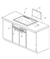
図1を参照して、1はいわゆるIHコンロと呼ばれているコンロ装置であって、カウンタトップCTに取り付けられたビルトイン式のものである。このコンロ装置1の天板11は耐熱性のガラス板で形成されており、内部の構造が見えないように着色はされているが、透光性を備えている。
Referring to FIG. 1, reference numeral 1 denotes a stove device called a so-called IH stove, which is a built-in type attached to a countertop CT. The
この天板11の後方にスクリーン12を取り付けた。そして、後述する映写ユニットから照射される光を天板11の透光部11aを通してスクリーン12を照らすことができるようにした。
A
このコンロ装置1はグリル扉21を備えたグリル庫2を有しており、そのグリル扉21の右側にはコントロール部13が収納自在に設けられている。
The stove device 1 has a
図2を参照して、天板11の下方には上述の映写ユニット3が配設されている。この映写ユニット3は内部に光源と、その光源の前に液晶式の画像表示部とが設けられており、光源からの光が画像表示部を透過し、さらに先端の設けたレンズを介して外部に光が照射されるものである。図示のように、映写ユニット3の光軸に対してスクリーン12が傾いているので、映写ユニット3内の画像表示部に、予め上部が縮小された、歪ませた画像を表示させ、スクリーン12に映写された状態で正常に表示されるようにした。
With reference to FIG. 2, the
映写ユニット3により映写する画像は複数種類の中から自在に切り替えられるように構成し、その切り替えはコントロール部13のスイッチで行うようにした。これら切り替えられる画像としては、例えばコンロ装置が消費する電力量やテレビ画像、あるいは調理レシピである。なお、コンロ装置の適所、例えば前板部分にスピーカを取り付けて、画像に合わせて音声を発音できるようにしてもよい。
An image projected by the
ところで、グリル庫2内に調理物を入れてグリル調理を行う場合、グリル扉21に設けたのぞき窓からグリル庫2の内部の調理物を観察し、焼け具合などをチェックする必要がある。ところが、グリル扉21ののぞき窓を覗くためには、腰をかがめなければならない。
By the way, when performing grill cooking by putting a food item in the
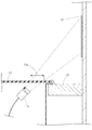
そこで、図3に示すように、カメラ27を設け、グリル庫2内をこのカメラ27で撮像して上記映写ユニット3を介してスクリーン12に映写するようにした。図3において、22はグリル扉21に連結された焼き網であり、調理物はこの焼き網22の上に載置される。そして、焼き網22の上方に位置してヒータ23を設けた。このヒータ23から照射される赤外線により調理物を加熱してグリル調理を行うようにした。
Therefore, as shown in FIG. 3, a
ヒータ23からの輻射熱がグリル庫2の天井板25を加熱しないようにすると共に、上方に放射された赤外線を反射させて調理物を効率よく加熱できるように、反射板24を設けた。そして、この反射板24に筒状の遮熱ガード24aを設け、その遮熱ガード24a内に位置するように、天井板25から保護筒部25aを延設させた。そして、その保護筒部25aの下端を耐熱性のガラス板26で封鎖し、保護筒部25a内にカメラ27をセットした。
The
なお、本発明は上記した形態に限定されるものではなく、本発明の要旨を逸脱しない範囲内において種々の変更を加えてもかまわない。 In addition, this invention is not limited to an above-described form, You may add a various change in the range which does not deviate from the summary of this invention.
1 コンロ装置
2 グリル庫
3 映写ユニット
11 天板
11a 透光部
12 スクリーン
13 コントロール部
21 グリル扉
23 ヒータ
24 反射板
24a 遮熱ガード
25 天井板
25a 保護筒部
26 ガラス板
27 カメラ
CT カウンタトップ
DESCRIPTION OF SYMBOLS 1
Claims (1)
Priority Applications (1)
| Application Number | Priority Date | Filing Date | Title |
|---|---|---|---|
| JP2007152545A JP4526552B2 (en) | 2007-06-08 | 2007-06-08 | Stove device |
Applications Claiming Priority (1)
| Application Number | Priority Date | Filing Date | Title |
|---|---|---|---|
| JP2007152545A JP4526552B2 (en) | 2007-06-08 | 2007-06-08 | Stove device |
Publications (2)
| Publication Number | Publication Date |
|---|---|
| JP2008304132A JP2008304132A (en) | 2008-12-18 |
| JP4526552B2 true JP4526552B2 (en) | 2010-08-18 |
Family
ID=40233007
Family Applications (1)
| Application Number | Title | Priority Date | Filing Date |
|---|---|---|---|
| JP2007152545A Expired - Fee Related JP4526552B2 (en) | 2007-06-08 | 2007-06-08 | Stove device |
Country Status (1)
| Country | Link |
|---|---|
| JP (1) | JP4526552B2 (en) |
Families Citing this family (4)
| Publication number | Priority date | Publication date | Assignee | Title |
|---|---|---|---|---|
| DE102015101174A1 (en) * | 2015-01-28 | 2016-07-28 | Miele & Cie. Kg | Hob and method for projecting an image |
| EP3460336B1 (en) * | 2017-09-22 | 2021-12-01 | WELBILT Deutschland GmbH | Cooking device, in particular commercial cooking device |
| JP7236644B2 (en) * | 2019-10-01 | 2023-03-10 | パナソニックIpマネジメント株式会社 | heating cooker |
| CN111810989A (en) * | 2020-06-11 | 2020-10-23 | 华帝股份有限公司 | Gas stove with projection device |
Family Cites Families (4)
| Publication number | Priority date | Publication date | Assignee | Title |
|---|---|---|---|---|
| JP3757358B2 (en) * | 2002-03-14 | 2006-03-22 | 三菱電機株式会社 | Electric cooker |
| JP2005056722A (en) * | 2003-08-05 | 2005-03-03 | Sanyo Electric Co Ltd | Heating cooker |
| JP2005133989A (en) * | 2003-10-28 | 2005-05-26 | Sanyo Electric Co Ltd | Heating cooker |
| JP2005304881A (en) * | 2004-04-23 | 2005-11-04 | Matsushita Electric Works Ltd | Kitchen device |
-
2007
- 2007-06-08 JP JP2007152545A patent/JP4526552B2/en not_active Expired - Fee Related
Also Published As
| Publication number | Publication date |
|---|---|
| JP2008304132A (en) | 2008-12-18 |
Similar Documents
| Publication | Publication Date | Title |
|---|---|---|
| JP6458249B2 (en) | refrigerator | |
| JP6808614B2 (en) | Induction heating cooking equipment | |
| KR102920403B1 (en) | Cooking apparatus | |
| US20200166276A1 (en) | Cooking appliance | |
| JPH11266944A (en) | System kitchen with projector and cooking place | |
| JP4526552B2 (en) | Stove device | |
| US10778876B2 (en) | Domestic appliance with optical monitoring device | |
| JP2019190770A (en) | Heating cooker | |
| JP6842955B2 (en) | Cooker | |
| US20180363922A1 (en) | A household appliance control unit | |
| CN102257328B (en) | Household appliance, in particular oven | |
| JP7426963B2 (en) | heating cooker | |
| JP7276846B2 (en) | Gas stove | |
| JP7489588B2 (en) | Cooking equipment | |
| CN221616820U (en) | Visual drawer of lens and cooking equipment | |
| JP2020067251A (en) | Cooking device | |
| US10295193B2 (en) | Cooking appliance, in particular for domestic use | |
| KR20250031619A (en) | Cooking appliance | |
| KR101052137B1 (en) | Cooker | |
| JP7315212B2 (en) | Gas stove | |
| KR20250010280A (en) | Cooking appliance | |
| CN212901622U (en) | induction cooker | |
| WO2017134216A1 (en) | An exhaust hood with a projector | |
| JP2016038122A (en) | Heating device | |
| CN120154224A (en) | Cooking Equipment |
Legal Events
| Date | Code | Title | Description |
|---|---|---|---|
| A621 | Written request for application examination |
Free format text: JAPANESE INTERMEDIATE CODE: A621 Effective date: 20090407 |
|
| A131 | Notification of reasons for refusal |
Free format text: JAPANESE INTERMEDIATE CODE: A131 Effective date: 20100223 |
|
| A521 | Request for written amendment filed |
Free format text: JAPANESE INTERMEDIATE CODE: A523 Effective date: 20100423 |
|
| TRDD | Decision of grant or rejection written | ||
| A01 | Written decision to grant a patent or to grant a registration (utility model) |
Free format text: JAPANESE INTERMEDIATE CODE: A01 Effective date: 20100525 |
|
| A01 | Written decision to grant a patent or to grant a registration (utility model) |
Free format text: JAPANESE INTERMEDIATE CODE: A01 |
|
| A61 | First payment of annual fees (during grant procedure) |
Free format text: JAPANESE INTERMEDIATE CODE: A61 Effective date: 20100601 |
|
| FPAY | Renewal fee payment (event date is renewal date of database) |
Free format text: PAYMENT UNTIL: 20130611 Year of fee payment: 3 |
|
| R150 | Certificate of patent or registration of utility model |
Free format text: JAPANESE INTERMEDIATE CODE: R150 |
|
| LAPS | Cancellation because of no payment of annual fees |