JP4523089B2 - Fuel cell stack - Google Patents
Fuel cell stack Download PDFInfo
- Publication number
- JP4523089B2 JP4523089B2 JP10320099A JP10320099A JP4523089B2 JP 4523089 B2 JP4523089 B2 JP 4523089B2 JP 10320099 A JP10320099 A JP 10320099A JP 10320099 A JP10320099 A JP 10320099A JP 4523089 B2 JP4523089 B2 JP 4523089B2
- Authority
- JP
- Japan
- Prior art keywords
- gas
- gas flow
- fuel cell
- grooves
- cell stack
- Prior art date
- Legal status (The legal status is an assumption and is not a legal conclusion. Google has not performed a legal analysis and makes no representation as to the accuracy of the status listed.)
- Expired - Fee Related
Links
Images


Classifications
-
- Y—GENERAL TAGGING OF NEW TECHNOLOGICAL DEVELOPMENTS; GENERAL TAGGING OF CROSS-SECTIONAL TECHNOLOGIES SPANNING OVER SEVERAL SECTIONS OF THE IPC; TECHNICAL SUBJECTS COVERED BY FORMER USPC CROSS-REFERENCE ART COLLECTIONS [XRACs] AND DIGESTS
- Y02—TECHNOLOGIES OR APPLICATIONS FOR MITIGATION OR ADAPTATION AGAINST CLIMATE CHANGE
- Y02E—REDUCTION OF GREENHOUSE GAS [GHG] EMISSIONS, RELATED TO ENERGY GENERATION, TRANSMISSION OR DISTRIBUTION
- Y02E60/00—Enabling technologies; Technologies with a potential or indirect contribution to GHG emissions mitigation
- Y02E60/30—Hydrogen technology
- Y02E60/50—Fuel cells
Landscapes
- Fuel Cell (AREA)
Description
【0001】
【発明の属する技術分野】
本発明は、電解質をアノード側電極とカソード側電極で挟んで構成される単位燃料電池セルを、セパレータを介して複数個積層した燃料電池スタックに関する。
【0002】
【従来の技術】
例えば、固体高分子型燃料電池は、高分子イオン交換膜(陽イオン交換膜)からなる電解質の両側にそれぞれアノード側電極およびカソード側電極を対設して構成された単位燃料電池セルを、セパレータによって挟持することにより構成されている。この固体高分子型燃料電池は、通常、単位燃料電池セルおよびセパレータを所定数だけ積層することにより、燃料電池スタックとして使用されている。
【0003】
この種の燃料電池において、アノード側電極に供給された燃料ガス、例えば、水素ガスは、触媒電極上で水素イオン化され、適度に加湿された電解質を介してカソード側電極側へと移動する。その間に生じた電子が外部回路に取り出され、直流の電気エネルギとして利用される。カソード側電極には、酸化剤ガス、例えば、酸素ガスあるいは空気が供給されているために、このカソード側電極において、前記水素イオン、前記電子および酸素ガスが反応して水が生成される。
【0004】
ところで、アノード側電極およびカソード側電極にそれぞれ燃料ガスおよび酸化剤ガスを供給するために、通常、触媒電極層(電極面)に導電性を有する多孔質層、例えば、多孔質カーボンペーパがセパレータにより挟持されるとともに、各セパレータの互いに対向する面には、均一な幅寸法に設定された1本または複数本のガス流路が設けられている。
【0005】
この場合、ガス流路内には、凝結水分や反応によって生成された水分が、液体(水)の状態で存在することがある。この水が多孔質層に蓄積されると、燃料ガスおよび酸化剤ガスの触媒電極層への拡散性が低下してしまい、セル性能が著しく悪くなるおそれがある。
【0006】
そこで、例えば、特開平6−267564号公報に開示されているように、アノード極に燃料を供給する燃料流路を有した燃料配流板と、カソード極に酸化剤を供給する酸化剤流路を有した酸化剤配流板とを具備し、前記酸化剤配流板の酸化剤流路の深さあるいは幅のうち、少なくともいずれか一方を酸化剤の上流流路域から下流流路域に沿って徐々に小さくした燃料電池が知られている。
【0007】
【発明が解決しようとする課題】
ところが、燃料ガスおよび酸化剤ガスをそれぞれ電極面に十分に供給するために、ガス流路がセパレータの面方向に蛇行して、あるいは周回して設けられている。このため、ガス流路がセパレータの面内で相当に長尺化しており、上記の従来技術では、酸化剤流路の上流流路域の深さが大きくなって前記セパレータ自体が相当に肉厚なものとなってしまう。これにより、燃料電池全体の小型化が容易に遂行されないという問題が指摘されている。しかも、ガス流路の上流から下流に向かって深さを徐々に小さくする加工作業が、極めて煩雑なものとなるという問題がある。
【0008】
本発明はこの種の問題を解決するものであり、良好なガス拡散性および排水性を確保するとともに、有効に小型化することが可能な燃料電池スタックを提供することを目的とする。
【0009】
【課題を解決するための手段】
本発明に係る燃料電池スタックでは、セパレータの面内に燃料ガスまたは酸化剤ガスの少なくともいずれかを含む流体を流す流体用通路を設けるとともに、この流体用通路は、ガス入口側からガス出口に向かって溝本数が減少する第1および第2ガス流路溝を備え、複数本の前記第1および第2ガス流路溝が一体的に合流する複数の集合部が設けられている。このため、セパレータの面内で流体が消費される際、第1ガス流路溝から第2ガス流路溝に溝本数が減少することにより、ガス出口側の単位面積当たりの反応分子数がガス入口側に比べて減少することがなく、電極面内での反応の均一化を図ることができる。
【0010】
しかも、複数本の第1および第2ガス流路溝の合流部位に集合部が設けられている。従って、集合部で流体に乱流が惹起され、電極面に対する燃料ガスおよび/または酸化剤ガスのガス拡散性を向上させることが可能になる。
【0011】
さらに、複数本の第1ガス流路溝から排出された燃料ガスおよび/または酸化剤ガスを集合部で合流させた後、複数本の第2ガス流路溝に分配している。このため、複数本の第2ガス流路溝間のガスの分配が均一に行われる。
【0012】
また、燃料電池スタックでは、第2ガス流路溝が2本以上に設定されているため、一方の第2ガス流路溝が生成水の結露等により閉塞しても、別の第2ガス流路溝に流体を流すことができる。これにより、セパレータの面内でガスの供給不足による濃度過電圧の増加を防止することができ、セル電圧を安定して得ることが可能になる。
【0013】
さらにまた、燃料電池スタックでは、第1ガス流路溝と第2ガス流路溝とが集合部を介して流れ方向を反転させている。このため、セパレータの面内には、発電面に対して隙間なく流体用通路を配置することができ、発電性能を有効に維持することが可能になる。
【0014】
【発明の実施の形態】
図1は、本発明の第1の実施形態に係る燃料電池スタック10の要部分解斜視図であり、図2は、前記燃料電池スタック10の概略縦断面説明図である。
【0015】
燃料電池スタック10は、単位燃料電池セル12と、この単位燃料電池セル12を挟持する第1および第2セパレータ14、16とを備え、必要に応じてこれらが複数組だけ積層されている。燃料電池スタック10は、全体として直方体状を有しており、例えば、短辺方向(矢印A方向)が重力方向に指向するとともに、長辺方向(矢印B方向)が水平方向に指向して配置される。
【0016】
単位燃料電池セル12は、固体高分子電解質膜18と、この電解質膜18を挟んで配設されるアノード側電極20およびカソード側電極22とを有するとともに、前記アノード側電極20および前記カソード側電極22には、例えば、多孔質層である多孔質カーボンペーパ等からなる第1および第2ガス拡散層24、26が配設される。
【0017】
単位燃料電池セル12の両側には、第1および第2ガスケット28、30が設けられ、前記第1ガスケット28は、アノード側電極20および第1ガス拡散層24を収納するための大きな開口部32を有する一方、前記第2ガスケット30は、カソード側電極22および第2ガス拡散層26を収納するための大きな開口部34を有する。単位燃料電池セル12と第1および第2ガスケット28、30とが、第1および第2セパレータ14、16によって挟持される。
【0018】
図1および図3に示すように、第1セパレータ14は、アノード側電極20に対向する面14aおよび反対側の面14bが長方形状に設定されており、例えば、長辺35aが水平方向に指向するとともに、短辺35bが重力方向に指向して配置される。長辺35aと短辺35bとの比は、例えば、1.5〜3:1程度に設定されている。
【0019】
第1セパレータ14の短辺35b側の両端縁部上部側には、水素ガス等の燃料ガスを通過させるための燃料ガス入口36aと、酸素ガスまたは空気である酸化剤ガスを通過させるための酸化剤ガス入口38aとが設けられる。第1セパレータ14の短辺35b側の両端縁部略中央側には、純水やエチレングリコールやオイル等の冷却媒体を通過させるための冷却媒体入口40aおよび冷却媒体出口40bが設けられるとともに、前記第1セパレータ14の短辺35b側の両端縁部下部側には、燃料ガス出口36bと酸化剤ガス出口38bとが燃料ガス入口36aおよび酸化剤ガス入口38aとは対角の位置に設けられている。
【0020】
第1セパレータ14の面14aには、燃料ガス入口36aと燃料ガス出口36bとに連通する燃料ガス流路(流体用通路)42が形成される。燃料ガス流路42は、複数本、例えば、6本(2m本)の第1ガス流路溝44a〜44fを備えており、前記第1ガス流路溝44a〜44fの一端側が燃料ガス入口36aに連通する。
【0021】
第1ガス流路溝44a〜44fは、燃料ガス入口36a側から酸化剤ガス入口38a側に向かって水平方向(矢印B方向)に延在した後、下方向(矢印A方向)に屈曲し、さらに冷却媒体入口40a側から冷却媒体出口40b側に向かって水平方向に延在する。冷却媒体出口40bの近傍では3本(m本)の第1ガス流路溝44a〜44cが第1集合部46に合流するとともに、残り3本(m本)の第1ガス流路溝44d〜44fが第2集合部48に合流する。
【0022】
第1および第2集合部46、48には、それぞれ2本(n本)の第2ガス流路溝50a、50bおよび50c、50dが連通し、前記第2ガス流路溝50a〜50dが水平方向に延在して燃料ガス出口36bに連通する。第1および第2集合部46、48の流路断面積は、それぞれ第2ガス流路溝50a、50bおよび50c、50dの合計流路断面積と同等に設定されている。
【0023】
図4に示すように、セパレータ14の面14aとは反対側の面14bには、冷却媒体入口40aと冷却媒体出口40bとに連通して冷却媒体流路(流体用通路)52a〜52dが設けられる。冷却媒体流路52a〜52dは、冷却媒体入口40aおよび冷却媒体出口40bに連通するそれぞれ1本の主流路溝54a、54bと、前記主流路溝54a、54b間に設けられる複数本、例えば、4本の分岐流路溝56とを備える。
【0024】
図1に示すように、第2セパレータ16は長方形状に形成されており、この第2セパレータ16の短辺側の両端縁部上部側には、燃料ガス入口58aおよび酸化剤ガス入口60aが貫通形成されるとともに、その両端縁部略中央部には、冷却媒体入口62aおよび冷却媒体出口62bが貫通形成される。第2セパレータ16の短辺側の両端縁部下部側には、燃料ガス出口58bおよび酸化剤ガス出口60bが燃料ガス入口58aおよび酸化剤ガス入口60aと対角位置になるように貫通形成されている。
【0025】
第2セパレータ16のカソード側電極22に対向する面16aには、図2に示すように、酸化剤ガス入口60aと酸化剤ガス出口60bとを連通する酸化剤ガス流路(流体用通路)64が形成される。酸化剤ガス流路64では、燃料ガス流路42と同様に、第1ガス流路溝66a〜66fと第2ガス流路溝68a〜68dとが図示しない第1および第2集合部を介して連通形成されており、その詳細な説明は省略する。
【0026】
第2セパレータ16の面16aとは反対側の面16bには、図1に示すように、冷却媒体入口62aと冷却媒体出口62bとを連通する冷却媒体流路70a〜70dが形成される。冷却媒体流路70a〜70dは、第1セパレータ14に設けられている冷却媒体流路52a〜52dと同様に構成されており、同一の構成要素には同一の参照符号を付して、その詳細な説明は省略する。
【0027】
このように構成される第1の実施形態に係る燃料電池スタック10の動作について、以下に説明する。
【0028】
燃料電池スタック10内には、燃料ガス(例えば、炭化水素を改質した水素を含むガス)が供給されるとともに、酸化剤ガスとして空気(または酸素ガス)が供給され、この燃料ガスが第1セパレータ14の燃料ガス入口36aから燃料ガス流路42に導入される。図3に示すように、燃料ガス流路42に供給された燃料ガスは、第1ガス流路溝44a〜44fに導入されて第1セパレータ14の面14aの長辺方向(矢印B方向)に沿って蛇行しながら重力方向に移動する。
【0029】
その際、燃料ガス中の水素ガスは、第1ガス拡散層24を通って単位燃料電池セル12のアノード側電極20に供給される。そして、未使用の燃料ガスは、第1ガス流路溝44a〜44fを通って第1および第2集合部46、48に一旦導入された後、第2ガス流路溝50a〜50dに分配されて矢印B方向に移動しながらアノード側電極20に供給される一方、残余の燃料ガスが燃料ガス出口36bから排出される。
【0030】
この場合、第1の実施形態では、燃料ガス入口36aに6本(2m本)の第1ガス流路溝44a〜44fが連通し、第1ガス流路溝44a〜44fがその途上で4本(2n本)の第2ガス流路溝50a〜50dに連通した後、燃料ガス出口36bに連通している。従って、第1セパレータ14の面14a内において、燃料ガス入口36aから燃料ガス出口36bに向かって溝本数が削減され、ガス消費による単位面積当たりの分子数の減少を阻止するとともに、前記燃料ガス出口36b側のガス流速を増加させることができる。このため、燃料ガス出口36b近傍に発生する反応生成水をガス流速の増加によって有効に前記燃料ガス出口36bに排出させることが可能になり、排水性の向上を図ることができる。
【0031】
また、第1ガス流路溝44a〜44fと第2ガス流路溝50a〜50dとの合流部位に、第1および第2集合部46、48が設けられている。これにより、第1ガス流路溝44a〜44cおよび44d〜44fに沿って供給される燃料ガスは、一旦、第1および第2集合部46、48に導入されるため、前記第1および第2集合部46、48でガスの乱流が惹起され、燃料ガス中の水素ガスをアノード側電極20に対して有効に拡散供給することが可能になるという効果が得られる。しかも、3本の第1ガス流路溝44a〜44cから排出された燃料ガスを第1集合部46で合流させた後、2本の第2ガス流路溝50a、50bに分配している。このため、2本の第2ガス流路溝50a、50b間の燃料ガスの分配が均一に行われるという利点がある。なお、他の2本の第2ガス流路溝50c、50dにおいても、同様である。
【0032】
さらに、第1および第2集合部46、48には、それぞれ2本ずつの流路溝(第2ガス流路溝50a、50bと50c、54d)が連通している。従って、一方の流路溝が生成水の結露等により閉塞したとしても、他の流路溝を介して燃料ガスの円滑な流れが許容される。これにより、第1セパレータ14の面14a内において、ガス供給不足による濃度過電圧の増加を防止することができ、燃料電池スタック10を安定して運転することが可能になるという利点がある。
【0033】
ここで、第1および第2集合部46、48の流路断面積は、分配部である第2ガス流路溝50a、50bおよび50c、50dのそれぞれの合計流路断面積と同等に設定されている。このため、第1および第2集合部46、48から第2ガス流路溝50a〜50dに燃料ガスを円滑に送り出すことが可能になる。
【0034】
さらにまた、第1ガス流路溝44a〜44fと第2ガス流路溝50a〜50dとは、第1および第2集合部46、48を介して流れ方向が反転されている。従って、第1セパレータ14の面14a内において、発電面に対して隙間なく流路を配置することができるという効果がある。
【0035】
ところで、第2セパレータ16では、酸化剤ガス入口60aから酸化剤ガス流路64に供給された空気が、面16aに沿って水平方向に蛇行しながら重力方向に移動する。その際、燃料ガス流路42に供給された燃料ガスと同様に、空気中の酸素ガスが第2ガス拡散層26からカソード側電極22に供給される一方、未使用の空気が酸化剤ガス出口60bから排出される。
【0036】
また、燃料電池スタック10には冷却媒体が供給されており、この冷却媒体は、第1および第2セパレータ14、16の冷却媒体入口40a、62aに供給される。図4に示すように、第1セパレータ14の冷却媒体入口40aに供給された冷却媒体は、冷却媒体流路52a〜52dを構成する各主流路溝54aに導入され、前記主流路溝54aに沿って上方向、水平方向および下方向に向かって流れる。冷却媒体は、それぞれの主流路溝54aから分岐された複数の分岐流路溝56に導入され、前記分岐流路溝56に沿って面14b内の略全面にわたり水平方向に流れた後、前記分岐流路溝56が合流する主流路溝54bを通って冷却媒体出口40bから排出される。
【0037】
一方、図1に示すように、第2セパレータ16の冷却媒体入口62aに供給された冷却媒体は、冷却媒体流路70a〜70dを通り、面16bの略全面にわたって直線的に移動した後、冷却媒体出口62bから排出される。
【0038】
図5は、本発明の第2の実施形態に係る燃料電池スタックを構成する第1セパレータ80の一方の面の正面説明図であり、図6は、本発明の第3の実施形態に係る燃料電池スタックを構成する第1セパレータ90の一方の面の正面説明図である。なお、上述した第1の実施形態に係る燃料電池スタック10を構成する第1セパレータ14と同一の構成要素には同一の参照符号を付して、その詳細な説明は省略する。
【0039】
図5に示すように、第2の実施形態に係る第1セパレータ80の面80aには、燃料ガス入口36aに連通する第1ガス流路溝44a〜44fと、燃料ガス出口36bに連通する第2ガス流路溝50a〜50dとが設けられるとともに、前記第1ガス流路溝44a〜44fと前記第2ガス流路溝50a〜50dとの合流部位に第1および第2集合部82、84が形成されている。
【0040】
第1集合部82は、第1ガス流路溝44cが連通する部位から第1ガス流路溝44bおよび44aが連通する部位に向かって(下方向に向かって)徐々に流路断面積が増加する第1三角形状部86を有し、この第1三角形状部86の下部側には、第2ガス流路溝50a、50bに向かうに従って流路断面積が徐々に減少する第2三角形状部88が設けられている。なお、第2集合部84は、上記した第1集合部82と同様に構成されており、同一の構成要素には同一の参照符号を付して、その詳細な説明は省略する。
【0041】
このように構成される第1セパレータ80では、第1ガス流路溝44a〜44fに供給された燃料ガスが第1および第2集合部82、84に導入される際、前記第1および第2集合部82、84に合流する燃料ガスが増加するに従って流路断面積が増加する。一方、第1および第2集合部82、84から第2ガス流路溝50a〜50dに燃料ガスが分配されるに従ってこの第1および第2集合部82、84の流路断面積が減少している。
【0042】
これにより、燃料ガスは、第1ガス流路溝44a〜44fから第1および第2集合部82、84に均等かつ円滑に集合するとともに、この第1および第2集合部82、84から第2ガス流路溝50a〜50dに円滑かつ均等に分配される。
このため、燃料ガスの流通が効率的に遂行されるという効果が得られる。
【0043】
図6に示すように、第3の実施形態に係る第1セパレータ90の面90aには、第1ガス流路溝44a〜44fと第2ガス流路溝50a〜50dの合流部位に対応して第1および第2集合部92、94が設けられている。第1および第2集合部92、94は略三角形状を有しており、第1ガス流路溝44a〜44fが合流するに従って(下方に向かって)流路断面積が増加している。
【0044】
このため、第3の実施形態では、燃料ガスが第1ガス流路溝44a〜44fを通って第1および第2集合部92、94に円滑かつ均等に合流される等、第2の実施形態と同様の効果が得られる。
【0045】
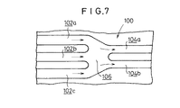
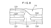
ところで、第1乃至第3の実施形態では、燃料ガス流路42を構成する第1ガス流路溝44a〜44fと第2ガス流路溝50a〜50dとが流れ方向を反転させるように構成されているが、図7および図8に示すように、同一の流れ方向を有する燃料ガス流路100、110を用いてもよい。
【0046】
この燃料ガス流路100では、図7に示すように、第1ガス流路溝102a〜102cと第2ガス流路溝104a、104bとが集合部106で合流している。この集合部106は、第1ガス流路溝102a〜102cを一旦合流させた後に同一の流れ方向に向かって両側が幅狭となり、第2ガス流路溝104a、104bに燃料ガスを分配するように構成されている。
【0047】
図8に示すように、燃料ガス流路110では、第1ガス流路溝112a〜112cと第2ガス流路溝114a、114bとの合流部位に集合部116が設けられるとともに、前記第1ガス流路溝112b、112cと前記第2ガス流路溝114a、114bとが同一直線上に配置されている。
【0048】
このように構成される燃料ガス流路100、110では、それぞれ3本(m本)の第1ガス流路溝102a〜102cおよび112a〜112cがそれぞれ2本(n本)の第2ガス流路溝104a、104bおよび114a、114bに絞られる際、一旦、単一の集合部106、116に集合される。このため、燃料ガスに乱流を発生させることができ、電極面への反応ガスの拡散性を有効に向上させることが可能になる。しかも、それぞれ3本の第1ガス流路溝102a〜102c、112a〜112cから排出された燃料ガスを集合部106、116で合流させた後、それぞれ2本の第2ガス流路溝104a、104b、114a、114bに分配している。このため、それぞれ2本の第2ガス流路溝104a、104b、114a、114b間の燃料ガスの分配が均一に行われるという利点がある。
【0049】
以上の説明では、基本的に3本の流路溝を2本の流路溝に絞る場合について説明したが、セパレータ面内で3本から2本への絞りを二段階に行う場合がある。これを、図9を用いて説明すると、入口側にそれぞれ第1ガス流路溝120a〜120iが設けられ、前記第1ガス流路溝120a〜120cが第2ガス流路溝122a、122bに絞られ、前記第1ガス流路溝120d〜120fが第2ガス流路溝122c、122dに絞られ、前記第1ガス流路溝120g〜120iが第2ガス流路溝122e、122fに絞られる。
【0050】
さらに、第2ガス流路溝122a〜122cが第3ガス流路溝124a、124bに絞られるとともに、第2ガス流路溝122d〜122fが第3ガス流路溝124c、124dに絞られる。
【0051】
なお、溝本数は3本から2本への絞り方の他、4本、3本および2本に絞る方法や、6本、4本および3本に絞る方法等、種々の絞り方が採用される。これにより、セパレータ面内での圧損を自由に調整することが可能になり、水の排出性やスタック内の流体分配の設計自由度が向上することになる。
【0052】
【発明の効果】
本発明に係る燃料電池スタックでは、燃料ガスおよび/または酸化剤ガスを含む流体を流す流体用通路が、ガス入口側にm本の第1ガス流路溝を有しかつガス出口側にn本(m>n)の第2ガス流路溝を有し、前記第1および第2ガス流路溝全体の合流部位に集合部が設けられている。このため、ガス入口側からガス出口側に向かって流れる流体が消費される際にガス流速が低下することを有効に阻止するとともに、集合部でガス乱流が惹起されて電極面へのガス拡散性を向上させることができる。しかも、流速の低下が阻止されるため、水の排出性が有効に向上することになり、電極反応面での水の凝結による発電性能の低下を防止することができる。さらに、複数本の第1ガス流路溝から排出された燃料ガスおよび/または酸化剤ガスを集合部で合流させた後、複数本の第2ガス流路溝に分配するようにしたため、前記複数本の第2ガス流路溝間のガスの分配が均一に行われる。
【図面の簡単な説明】
【図1】本発明の第1の実施形態に係る燃料電池スタックの要部分解斜視図である。
【図2】前記燃料電池スタックの概略縦断面説明図である。
【図3】前記燃料電池スタックを構成する第1セパレータの一方の面の正面説明図である。
【図4】前記第1セパレータの他方の面の正面説明図である。
【図5】本発明の第2の実施形態に係る燃料電池スタックを構成する第1セパレータの一方の面の正面説明図である。
【図6】本発明の第3の実施形態に係る燃料電池スタックを構成する第1セパレータの一方の面の正面説明図である。
【図7】流れ方向が同一である場合の燃料ガス流路の一部説明図である。
【図8】流れ方向が同一である場合の他の燃料ガス流路の一部説明図である。
【図9】流路溝を3本から2本に二段階に絞る場合の説明図である。
【符号の説明】
10…燃料電池スタック 12…単位燃料電池セル
14、16…セパレータ
14a、14b、16a、16b、80a、90a…面
18…電解質膜 20…アノード側電極
22…カソード側電極 24、26…拡散層
36a、58a…燃料ガス入口 36b、58b…燃料ガス出口
38a、60a…酸化剤ガス入口 38b、60b…酸化剤ガス出口
40a、62a、…冷却媒体入口 40b、62b…冷却媒体出口
42、100、110…燃料ガス流路
44a〜44f、50a〜50d、66a〜66f、68a〜68d、102a、102b、112a〜112c、114a、114b…ガス流路溝
46、48、82、84、92、94、106、116…集合部
52a〜52d、70a〜70d…冷却媒体流路
64…酸化剤ガス流路
80、90…セパレータ[0001]
BACKGROUND OF THE INVENTION
The present invention relates to a fuel cell stack in which a plurality of unit fuel cells each having an electrolyte sandwiched between an anode side electrode and a cathode side electrode are stacked via a separator.
[0002]
[Prior art]
For example, a solid polymer type fuel cell has a unit fuel cell formed by arranging an anode side electrode and a cathode side electrode on both sides of an electrolyte made of a polymer ion exchange membrane (cation exchange membrane). It is comprised by pinching by. This polymer electrolyte fuel cell is usually used as a fuel cell stack by stacking a predetermined number of unit fuel cells and separators.
[0003]
In this type of fuel cell, fuel gas, for example, hydrogen gas, supplied to the anode electrode is hydrogen ionized on the catalyst electrode and moves to the cathode electrode side via an appropriately humidified electrolyte. Electrons generated in the meantime are taken out to an external circuit and used as direct current electric energy. Since an oxidant gas, for example, oxygen gas or air, is supplied to the cathode side electrode, the hydrogen ions, the electrons and the oxygen gas react with each other to generate water at the cathode side electrode.
[0004]
By the way, in order to supply the fuel gas and the oxidant gas to the anode side electrode and the cathode side electrode, respectively, a porous layer having conductivity on the catalyst electrode layer (electrode surface), for example, porous carbon paper is usually separated by a separator. One or a plurality of gas flow paths having a uniform width dimension are provided on the surfaces of the separators that are sandwiched and opposed to each other.
[0005]
In this case, condensed moisture and moisture generated by the reaction may exist in a liquid (water) state in the gas channel. When this water is accumulated in the porous layer, the diffusibility of the fuel gas and the oxidant gas to the catalyst electrode layer is lowered, and the cell performance may be remarkably deteriorated.
[0006]
Therefore, for example, as disclosed in Japanese Patent Application Laid-Open No. 6-267564, a fuel distribution plate having a fuel flow path for supplying fuel to the anode electrode and an oxidant flow path for supplying oxidant to the cathode electrode are provided. An oxidant flow plate having at least one of the depth and width of the oxidant flow channel of the oxidant flow plate from the upstream flow channel region of the oxidant to the downstream flow channel region. Smaller fuel cells are known.
[0007]
[Problems to be solved by the invention]
However, in order to sufficiently supply the fuel gas and the oxidant gas to the electrode surfaces, the gas flow paths are provided so as to meander or circulate in the surface direction of the separator. For this reason, the gas flow path is considerably long in the plane of the separator, and in the above-described prior art, the depth of the upstream flow path area of the oxidant flow path is increased, and the separator itself is considerably thick. It will become something. As a result, a problem has been pointed out that miniaturization of the entire fuel cell cannot be easily performed. In addition, there is a problem that the processing operation for gradually decreasing the depth from the upstream side to the downstream side of the gas flow path becomes extremely complicated.
[0008]
The present invention solves this type of problem, and an object of the present invention is to provide a fuel cell stack that can ensure good gas diffusibility and drainage and can be effectively downsized.
[0009]
[Means for Solving the Problems]
In a fuel cell stack according to the present onset bright, provided with a fluid passage for flowing a fluid containing at least one of the fuel gas or oxidant gas into the surface of the separator, the fluid passage, the gas outlet from the gas inlet side A plurality of first and second gas flow channel grooves whose number of grooves decreases toward the groove are provided, and a plurality of collecting portions where the plurality of first and second gas flow channel grooves merge together are provided. For this reason, when the fluid is consumed in the surface of the separator, the number of reaction molecules per unit area on the gas outlet side is reduced by reducing the number of grooves from the first gas passage groove to the second gas passage groove. There is no decrease compared to the inlet side, and the reaction can be made uniform in the electrode plane.
[0010]
In addition, a collective portion is provided at a confluence portion of the plurality of first and second gas flow channel grooves. Accordingly, turbulence is induced in the fluid at the gathering portion, and the gas diffusibility of the fuel gas and / or the oxidant gas with respect to the electrode surface can be improved.
[0011]
Further, the fuel gas and / or the oxidant gas discharged from the plurality of first gas flow channel grooves are merged at the collecting portion and then distributed to the plurality of second gas flow channel grooves. For this reason, the gas is uniformly distributed between the plurality of second gas flow channel grooves.
[0012]
Further, in the fuel cell stack, the second gas flow passage is set to more than two, even if one of the second gas flow passage grooves are closed by the produced water condensation, etc., different second gas A fluid can be allowed to flow in the flow channel. As a result, it is possible to prevent an increase in concentration overvoltage due to insufficient supply of gas in the plane of the separator, and it becomes possible to stably obtain the cell voltage.
[0013]
Furthermore, in the fuel cell stack, a first gas flow passage grooves and the second gas flow passage groove is to reverse the flow direction through the collection section. For this reason, the passage for fluid can be arranged in the plane of the separator without a gap with respect to the power generation surface, and the power generation performance can be effectively maintained .
[0014]
DETAILED DESCRIPTION OF THE INVENTION
FIG. 1 is an exploded perspective view of a main part of a
[0015]
The
[0016]
The
[0017]
First and
[0018]
As shown in FIGS. 1 and 3, the
[0019]
A
[0020]
A fuel gas passage (fluid passage) 42 communicating with the
[0021]
The first
[0022]
Two (n) second gas
[0023]
As shown in FIG. 4, the
[0024]
As shown in FIG. 1, the
[0025]
On the surface 16a of the
[0026]
As shown in FIG. 1, cooling
[0027]
The operation of the
[0028]
In the
[0029]
At that time, the hydrogen gas in the fuel gas is supplied to the
[0030]
In this case, in the first embodiment, six (2m) first
[0031]
Moreover, the 1st and
[0032]
Furthermore, two flow channel grooves (second gas
[0033]
Here, the flow passage cross-sectional areas of the first and
[0034]
Furthermore, the flow directions of the first gas
[0035]
Incidentally, in the
[0036]
A cooling medium is supplied to the
[0037]
On the other hand, as shown in FIG. 1, the cooling medium supplied to the cooling
[0038]
FIG. 5 is a front explanatory view of one surface of the
[0039]
As shown in FIG. 5, on the
[0040]
In the first collecting
[0041]
In the
[0042]
Thus, the fuel gas is uniformly and smoothly gathered from the first
For this reason, the effect that the distribution of the fuel gas is efficiently performed is obtained.
[0043]
As shown in FIG. 6, the surface 90 a of the
[0044]
For this reason, in the third embodiment, the fuel gas is smoothly and evenly joined to the first and
[0045]
By the way, in the first to third embodiments, the first
[0046]
In the fuel
[0047]
As shown in FIG. 8, in the fuel
[0048]
In the fuel
[0049]
In the above description, the case where the three flow channel grooves are basically narrowed down to the two flow channel grooves has been described. However, the restriction from three to two may be performed in two stages within the separator surface. This will be described with reference to FIG. 9. First gas
[0050]
Further, the second
[0051]
Note that the number of grooves is not limited from 3 to 2, but various methods such as 4, 3 and 2 and 6, 4 and 3 are used. The As a result, the pressure loss in the separator surface can be freely adjusted, and the water discharge performance and the degree of freedom in designing the fluid distribution in the stack are improved.
[0052]
【The invention's effect】
In the fuel cell stack according to the present invention, the fluid passage for flowing the fluid containing the fuel gas and / or the oxidant gas has m first gas passage grooves on the gas inlet side and n on the gas outlet side. (M> n) second gas flow path grooves are provided, and a gathering portion is provided at a confluence portion of the entire first and second gas flow path grooves. For this reason, when the fluid flowing from the gas inlet side toward the gas outlet side is consumed, the gas flow velocity is effectively prevented from being lowered, and gas turbulence is induced in the collecting portion to diffuse the gas to the electrode surface. Can be improved. In addition, since the decrease in the flow velocity is prevented, the water discharge performance is effectively improved, and the decrease in power generation performance due to the condensation of water on the electrode reaction surface can be prevented. In addition, since the fuel gas and / or the oxidant gas discharged from the plurality of first gas flow channel grooves are merged at the gathering portion, they are distributed to the plurality of second gas flow channel grooves. The gas is uniformly distributed between the second gas channel grooves of the book.
[Brief description of the drawings]
FIG. 1 is an exploded perspective view of a main part of a fuel cell stack according to a first embodiment of the present invention.
FIG. 2 is a schematic vertical sectional view of the fuel cell stack.
FIG. 3 is a front explanatory view of one surface of a first separator constituting the fuel cell stack.
FIG. 4 is a front explanatory view of the other surface of the first separator.
FIG. 5 is an explanatory front view of one surface of a first separator constituting a fuel cell stack according to a second embodiment of the present invention.
FIG. 6 is an explanatory front view of one surface of a first separator constituting a fuel cell stack according to a third embodiment of the present invention.
FIG. 7 is a partial explanatory diagram of a fuel gas flow path when the flow directions are the same.
FIG. 8 is a partial explanatory diagram of another fuel gas flow path when the flow direction is the same.
FIG. 9 is an explanatory diagram in the case of narrowing the flow channel groove from three to two in two stages.
[Explanation of symbols]
DESCRIPTION OF
Claims (5)
前記セパレータの面内には、前記アノード側電極に供給される燃料ガスまたは前記カソード側電極に供給される酸化剤ガスのうち、少なくともいずれか一方を含む流体を流す流体用通路が設けられるとともに、
前記流体用通路は、ガス入口側に形成されるm本(mは自然数)の第1ガス流路溝と、
ガス出口側に形成されるn本(nは自然数、m>n)の第2ガス流路溝と、
m本の前記第1ガス流路溝とn本の前記第2ガス流路溝とを合流する合流部位に設けられ、m本未満の複数本の該第1ガス流路溝とn本未満の複数本の該第2ガス流路溝とをそれぞれ一体的に連通する複数の集合部と、
を備えることを特徴とする燃料電池スタック。A fuel cell stack in which a plurality of polymer electrolyte unit fuel cells each having a solid polymer electrolyte membrane sandwiched between an anode electrode and a cathode electrode are stacked via a separator,
In the surface of the separator, a fluid passage is provided for flowing a fluid containing at least one of the fuel gas supplied to the anode side electrode or the oxidant gas supplied to the cathode side electrode,
The fluid passage includes m (m is a natural number) first gas passage grooves formed on the gas inlet side,
N (n is a natural number, m> n) second gas passage grooves formed on the gas outlet side;
Provided at a merging site where the m first gas flow channel grooves and the n second gas flow channel grooves are joined, and less than m first gas flow channel grooves and less than n gas flow channels. A plurality of collecting portions integrally communicating with the plurality of second gas flow path grooves;
A fuel cell stack comprising:
前記第2ガス流路溝に隣接して配置され、前記第2ガス流路溝に向かうに従って流路断面積が減少する第2三角形状部と、
を有することを特徴とする燃料電池スタック。The fuel cell stack according to any one of claims 1 to 3, wherein the collecting portion is disposed adjacent to the first gas flow passage grooves, and follow the first gas flow passage grooves are merged A first triangular portion in which the cross-sectional area of the channel increases ;
A second triangular portion disposed adjacent to the second gas flow channel groove and having a flow channel cross-sectional area that decreases toward the second gas flow channel groove;
A fuel cell stack comprising:
Priority Applications (2)
| Application Number | Priority Date | Filing Date | Title |
|---|---|---|---|
| JP10320099A JP4523089B2 (en) | 1999-04-09 | 1999-04-09 | Fuel cell stack |
| US09/517,535 US6255011B1 (en) | 1998-03-02 | 2000-03-01 | Fuel cell stack |
Applications Claiming Priority (1)
| Application Number | Priority Date | Filing Date | Title |
|---|---|---|---|
| JP10320099A JP4523089B2 (en) | 1999-04-09 | 1999-04-09 | Fuel cell stack |
Publications (3)
| Publication Number | Publication Date |
|---|---|
| JP2000294261A JP2000294261A (en) | 2000-10-20 |
| JP2000294261A5 JP2000294261A5 (en) | 2006-05-25 |
| JP4523089B2 true JP4523089B2 (en) | 2010-08-11 |
Family
ID=14347886
Family Applications (1)
| Application Number | Title | Priority Date | Filing Date |
|---|---|---|---|
| JP10320099A Expired - Fee Related JP4523089B2 (en) | 1998-03-02 | 1999-04-09 | Fuel cell stack |
Country Status (1)
| Country | Link |
|---|---|
| JP (1) | JP4523089B2 (en) |
Families Citing this family (22)
| Publication number | Priority date | Publication date | Assignee | Title |
|---|---|---|---|---|
| KR100482419B1 (en) * | 1999-11-08 | 2005-04-14 | 마쯔시다덴기산교 가부시키가이샤 | Polymer electrolyte fuel cell |
| US6878477B2 (en) * | 2001-05-15 | 2005-04-12 | Hydrogenics Corporation | Fuel cell flow field plate |
| JP5098128B2 (en) * | 2001-09-14 | 2012-12-12 | トヨタ自動車株式会社 | Fuel cell |
| KR100539649B1 (en) | 2002-12-02 | 2005-12-29 | 산요덴키가부시키가이샤 | Separator for fuel cell and fuel cell using the same |
| DE10323644B4 (en) * | 2003-05-26 | 2009-05-28 | Daimler Ag | Fuel cell with adaptation of the local area-specific gas flows |
| TWM248036U (en) * | 2003-07-14 | 2004-10-21 | Asia Pacific Fuel Cell Tech | Flow field structure of fuel battery |
| JP2005251699A (en) * | 2004-03-08 | 2005-09-15 | Mitsubishi Electric Corp | Fuel cell |
| JP2005268110A (en) * | 2004-03-19 | 2005-09-29 | Mitsubishi Electric Corp | Fuel cell separator |
| JP5017780B2 (en) * | 2005-02-04 | 2012-09-05 | 住友金属工業株式会社 | Flow path design method for fuel cell separator |
| JP4673110B2 (en) * | 2005-03-30 | 2011-04-20 | 本田技研工業株式会社 | Fuel cell |
| JP4972891B2 (en) * | 2005-08-05 | 2012-07-11 | トヨタ自動車株式会社 | Fuel cell separator channel structure |
| WO2007018156A1 (en) | 2005-08-05 | 2007-02-15 | Matsushita Electric Industrial Co., Ltd. | Separator for fuel cell and fuel cell |
| JP4857750B2 (en) * | 2005-12-09 | 2012-01-18 | 株式会社日立製作所 | Polymer electrolyte fuel cell |
| US7790324B2 (en) * | 2006-02-02 | 2010-09-07 | Panasonic Corporation | Separator plate and fuel cell |
| JP5056637B2 (en) * | 2008-07-16 | 2012-10-24 | パナソニック株式会社 | Fuel cell separator |
| EP2224524B1 (en) * | 2009-02-12 | 2017-04-19 | Belenos Clean Power Holding AG | Fuel cell structure and separator plate for use therein |
| US8568941B2 (en) | 2009-03-04 | 2013-10-29 | Panasonic Corporation | Fuel cell separator and fuel cell including same |
| CN102341945B (en) * | 2009-03-04 | 2015-01-21 | 松下电器产业株式会社 | Separator for fuel cell, and fuel cell comprising same |
| WO2011118138A1 (en) * | 2010-03-25 | 2011-09-29 | パナソニック株式会社 | Direct oxidation fuel cell |
| JP6772200B2 (en) | 2018-01-09 | 2020-10-21 | 本田技研工業株式会社 | Power generation cell |
| DE102020128279A1 (en) | 2020-10-28 | 2022-04-28 | Audi Aktiengesellschaft | bipolar plate and fuel cell stack |
| CN115642267B (en) * | 2022-11-04 | 2023-04-11 | 北京朔景新能源科技有限公司 | Fuel cell, and plate and bipolar plate assembly for fuel cell |
Citations (7)
| Publication number | Priority date | Publication date | Assignee | Title |
|---|---|---|---|---|
| JPS56134473A (en) * | 1980-03-25 | 1981-10-21 | Toshiba Corp | Unit cell for fuel cell |
| JPS62271354A (en) * | 1986-05-20 | 1987-11-25 | Toshiba Corp | Fuel cell |
| JPS63195967A (en) * | 1987-02-10 | 1988-08-15 | Toshiba Corp | Fuel cell |
| JPH1116590A (en) * | 1997-06-26 | 1999-01-22 | Matsushita Electric Ind Co Ltd | Fuel cell |
| JPH11144746A (en) * | 1997-11-11 | 1999-05-28 | Fuji Electric Co Ltd | Phosphoric acid type fuel cell |
| JPH11297341A (en) * | 1998-04-03 | 1999-10-29 | Murata Mfg Co Ltd | Solid electrolyte type fuel cell |
| JP2000182631A (en) * | 1998-12-18 | 2000-06-30 | Toyota Motor Corp | Separator for fuel cell |
Family Cites Families (1)
| Publication number | Priority date | Publication date | Assignee | Title |
|---|---|---|---|---|
| JP4205774B2 (en) * | 1998-03-02 | 2009-01-07 | 本田技研工業株式会社 | Fuel cell |
-
1999
- 1999-04-09 JP JP10320099A patent/JP4523089B2/en not_active Expired - Fee Related
Patent Citations (7)
| Publication number | Priority date | Publication date | Assignee | Title |
|---|---|---|---|---|
| JPS56134473A (en) * | 1980-03-25 | 1981-10-21 | Toshiba Corp | Unit cell for fuel cell |
| JPS62271354A (en) * | 1986-05-20 | 1987-11-25 | Toshiba Corp | Fuel cell |
| JPS63195967A (en) * | 1987-02-10 | 1988-08-15 | Toshiba Corp | Fuel cell |
| JPH1116590A (en) * | 1997-06-26 | 1999-01-22 | Matsushita Electric Ind Co Ltd | Fuel cell |
| JPH11144746A (en) * | 1997-11-11 | 1999-05-28 | Fuji Electric Co Ltd | Phosphoric acid type fuel cell |
| JPH11297341A (en) * | 1998-04-03 | 1999-10-29 | Murata Mfg Co Ltd | Solid electrolyte type fuel cell |
| JP2000182631A (en) * | 1998-12-18 | 2000-06-30 | Toyota Motor Corp | Separator for fuel cell |
Also Published As
| Publication number | Publication date |
|---|---|
| JP2000294261A (en) | 2000-10-20 |
Similar Documents
| Publication | Publication Date | Title |
|---|---|---|
| JP4523089B2 (en) | Fuel cell stack | |
| JP4590047B2 (en) | Fuel cell stack | |
| US6255011B1 (en) | Fuel cell stack | |
| US7112385B2 (en) | Flow restrictors in fuel cell flow-field | |
| KR101693993B1 (en) | Bipolar plate for fuel cell | |
| EP2587576B1 (en) | Fuel cell stack | |
| JP4753599B2 (en) | Fuel cell | |
| JP4960415B2 (en) | Fuel cell | |
| US10601064B2 (en) | Fluid distribution device for distributing at least two fluids of a fuel cell | |
| JP7346777B2 (en) | Bipolar plate for electrochemical systems | |
| US6413664B1 (en) | Fuel cell separator plate with discrete fluid distribution features | |
| JPH11250923A (en) | Fuel cell | |
| JP2000331691A (en) | Fuel cell stack | |
| JP3980194B2 (en) | Fuel cell | |
| JP5449838B2 (en) | Fuel cell stack | |
| JP2015133215A (en) | fuel cell stack | |
| JP2000123848A (en) | Fuel cell | |
| JP5301406B2 (en) | Fuel cell | |
| JP5297990B2 (en) | Fuel cell | |
| JP2004047214A (en) | Fuel cell | |
| JP5491231B2 (en) | Fuel cell | |
| JP4031952B2 (en) | Fuel cell | |
| KR20060134147A (en) | Fuel cell reactant flow fields that maximize planform utilization | |
| JP5385033B2 (en) | Fuel cell | |
| JP4651807B2 (en) | Fuel cell |
Legal Events
| Date | Code | Title | Description |
|---|---|---|---|
| A521 | Written amendment |
Free format text: JAPANESE INTERMEDIATE CODE: A523 Effective date: 20060404 |
|
| A621 | Written request for application examination |
Free format text: JAPANESE INTERMEDIATE CODE: A621 Effective date: 20060404 |
|
| A977 | Report on retrieval |
Free format text: JAPANESE INTERMEDIATE CODE: A971007 Effective date: 20080526 |
|
| A131 | Notification of reasons for refusal |
Free format text: JAPANESE INTERMEDIATE CODE: A131 Effective date: 20090512 |
|
| A521 | Written amendment |
Free format text: JAPANESE INTERMEDIATE CODE: A523 Effective date: 20090710 |
|
| A131 | Notification of reasons for refusal |
Free format text: JAPANESE INTERMEDIATE CODE: A131 Effective date: 20100223 |
|
| A521 | Written amendment |
Free format text: JAPANESE INTERMEDIATE CODE: A523 Effective date: 20100420 |
|
| TRDD | Decision of grant or rejection written | ||
| A01 | Written decision to grant a patent or to grant a registration (utility model) |
Free format text: JAPANESE INTERMEDIATE CODE: A01 Effective date: 20100525 |
|
| A01 | Written decision to grant a patent or to grant a registration (utility model) |
Free format text: JAPANESE INTERMEDIATE CODE: A01 |
|
| A61 | First payment of annual fees (during grant procedure) |
Free format text: JAPANESE INTERMEDIATE CODE: A61 Effective date: 20100527 |
|
| R150 | Certificate of patent or registration of utility model |
Free format text: JAPANESE INTERMEDIATE CODE: R150 |
|
| FPAY | Renewal fee payment (event date is renewal date of database) |
Free format text: PAYMENT UNTIL: 20130604 Year of fee payment: 3 |
|
| FPAY | Renewal fee payment (event date is renewal date of database) |
Free format text: PAYMENT UNTIL: 20130604 Year of fee payment: 3 |
|
| FPAY | Renewal fee payment (event date is renewal date of database) |
Free format text: PAYMENT UNTIL: 20140604 Year of fee payment: 4 |
|
| LAPS | Cancellation because of no payment of annual fees |