JP4521576B2 - Dental equipment support equipment - Google Patents
Dental equipment support equipment Download PDFInfo
- Publication number
- JP4521576B2 JP4521576B2 JP2000157201A JP2000157201A JP4521576B2 JP 4521576 B2 JP4521576 B2 JP 4521576B2 JP 2000157201 A JP2000157201 A JP 2000157201A JP 2000157201 A JP2000157201 A JP 2000157201A JP 4521576 B2 JP4521576 B2 JP 4521576B2
- Authority
- JP
- Japan
- Prior art keywords
- lever
- force
- damper
- rotation
- fulcrum
- Prior art date
- Legal status (The legal status is an assumption and is not a legal conclusion. Google has not performed a legal analysis and makes no representation as to the accuracy of the status listed.)
- Expired - Fee Related
Links
Images


Description
【0001】
【発明の属する技術分野】
本発明は、診察又は治療の際に横臥姿勢にある患者に機器を接近させ、診察又は治療が終了したとき患者から機器を離隔させて患者が診療ユニットから離脱する際に邪魔にならないようにした歯科用機器の支持装置に関するものである。
【0002】
【従来の技術】
歯科診療又は治療の際には、患者は診療ユニットに横臥した姿勢を維持する。
この状態で診療又は診察(診療)が行なわれた後、診療ユニットから起き上がって離脱する。このように、患者が診療ユニットの周辺では立ち上がった状態で、且つ診療時に横臥する状態となるのは、歯科治療に特有のものである。
【0003】
最近では診療の際に顕微鏡を用いることがあるが、この顕微鏡は重量が大きく且つ診療時には位置を維持することが必須であるため、所定の支持装置に支持されるのが一般的である。
【0004】
このような支持装置としては、移動可能な台車に柱を取り付け、該柱に垂直軸及び水平軸を中心として夫々回転可能なレバーを取り付け、このレバーの先端に顕微鏡を取り付けて構成されるのが一般的である。また顕微鏡は医師によって所望の位置に移動し、移動位置で停止した状態を維持し得るように構成されている。支持装置に於ける前記機構は、顕微鏡の重量と、レバーの重力の作用力と回転軸からの距離とに応じた下降力に対し、各回転部分或いは特定の回転部分等に作用する摩擦抵抗の値を大きく設定することで実現している。
【0005】
【発明が解決しようとする課題】
上記の如く、回転部分等に於ける摩擦力をレバーに作用する下降力よりも大きく設定して顕微鏡の位置を維持させるように構成した支持装置では、該顕微鏡を移動させる場合、人による操作が必須である。即ち、患者に対する診療が終了して患者が診療ユニットから立ち上がるとき、顕微鏡を診療ユニットから充分に離隔させた退避位置まで手で移動させる操作が必須である。この顕微鏡を退避位置まで退避させる操作は、診療が終了した医師にとって煩雑な作業であり、より簡単な操作で顕微鏡を診療ユニットから退避させ得る支持装置の開発が要求されている。
【0006】
本発明の目的は、機器を所定の高さまで移動させることでレバーを回転させ、この回転が予め設定された範囲より上位置のとき、ダンパーによって退避させるように構成した歯科用機器の支持装置を提供することにある。
【0007】
【課題を解決するための手段】
上記課題を解決するために本発明に係る歯科用機器の支持装置は、診察又は治療に用いる機器を上部から患者に接近させ又は離隔させる歯科用機器の支持装置であって、一方側に機器を取り付けると共に他方側が回転支点を介して回動可能に支持されるレバーと、前記レバーに該レバーの機器を取り付けた側を上昇させる方向の力を付与するダンパーとを有し、機器とレバーとダンパーの重力の作用力と回転支点からの距離とに応じて生じる下向きの回転力とダンパーの強さと該ダンパーの設置位置とに応じて生じる上向きの回転力との合成による合成力と、レバー及びレバーの回転に連回転するダンパーを含む部材の各支点における摩擦抵抗とレバーの回転に連摺動するダンパーのピストンとシリンダーを含む摺動部に於ける摩擦抵抗による回転阻止力とを、レバーがレバーの回転角度における所定の角度範囲にあるときに前記合成力が回転阻止力よりも小さくなって現在の角度を維持し、前記角度範囲より上位置にあるとき前記合成力が回転阻止力よりも大きくなってレバーの機器を取り付けた側が回転支点を中心として上昇するように回転させる設定としたものである。
【0008】
上記支持装置では、診察或いは診療に用いる機器(例えば顕微鏡や照明器具或いは治療器具類を搭載したトレー等、以下単に「機器」という)を一方側に取り付けると共に、他方側が回転支点を介して柱や壁等に回転可能に支持されたレバーにダンパーを取り付け、該ダンパーによってレバーを常に回転支点を中心として機器を取り付けた一方側を上昇させる方向の力を付与することによって、レバーには、該レバーに作用する機器の重量,レバーの重量、ダンパーの重量と回転支点からこれらの力が作用する位置までの距離に応じた下向きの回転力と、ダンパーによる上向きの回転力との合成による上向き、又は下向きの回転力が作用する。
【0009】
レバーに作用する上向きの回転力は、ダンパーが発生する力(ダンパー力)と、ダンパーのレバーに対する角度(レバーの長手方向とダンパーの軸のなす角度)とに応じて決まる。即ち、ダンパー力を一定とした場合、レバーの回転角度が変化すると、この変化に伴ってダンパーのレバーに対する角度が変化し、これに応じてレバーに作用する上向きの回転力が変化する。
【0010】
従って、ダンパーの設置位置(例えばロッドのレバーに対する取付位置、又はシリンダーの取付位置)を調整することで、レバーに対するダンパーの角度を変化させることが出来、レバーが同一の角度であっても該レバーに作用する上向きの回転力を変化させることが出来る。
【0011】
このように、レバーに作用する上向きの回転力は、ダンパー力,ダンパーの設置位置を個別に、或いは同時に調整することで設定することが出来る。
【0012】
レバーに作用する下向きの回転力は、レバーの回転支点から機器の重量の作用線,レバーの重量の作用線、ダンパーの重量の作用線までの距離に応じて設定される。レバーの回転角度が変化するのに伴って、レバーの回転支点から前記各作用線までの距離が変化するが、この変化によるレバーに作用する下向きの回転力の変化は大きなものではなく、無視することが可能である。従って、レバーの回転角度に関わらず、該レバーに作用する下向きの回転力は一定であるとして差し支えはない。
【0013】
従って、回転支点に摩擦が作用していないと仮定したとき、ダンパー力,ダンパーの設置位置の設定を個別に又は同時に行なうことで、レバーに作用する下向きの回転力と上向きの回転力を平衡させることが出来る。この平衡状態は、レバーを如何なる角度で平衡させるか、に応じて、ダンパー力,ダンパーの設置位置を設定することで得ることが出来る。前記レバーの平衡状態は、予め設定された角度範囲に限定され、レバーが前記角度範囲から逸脱すると該レバーには下向きの回転力、或いは上向きの回転力が作用することになる。
【0014】
このため、レバー及びレバーの回転に連回転(レバーの回転に伴って回転)するダンパーを含む部材の各支点やレバーの回転に連摺動(レバーの回転に伴って摺動)するダンパーのピストンとシリンダーを含む摺動部などに摩擦を作用させることによって、この摩擦抵抗を回転支点に於ける回転阻止力として作用させることで、レバーに作用する下向きの回転力或いは上向きの回転力に対抗させることが出来る。
【0015】
そして上記摩擦力を適宜調整して設定することで、レバーが、ダンパー力,ダンパーの設置位置の設定による該レバーの平衡範囲から逸脱した場合であっても、レバーの回転を阻止して停止状態を維持することが出来る。
【0016】
従って、ダンパー力,ダンパーの設置位置,上記種々の摩擦力を適宜調整することで、レバーを停止させておく角度範囲を設定することが出来、且つレバーを前記角度範囲から逸脱させることで該レバーに上向きの回転力を作用させて回転させ、これにより、機器を上昇させて患者から離隔させることが出来る。
【0017】
【発明の実施の形態】
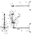
以下、上記支持装置の好ましい実施形態について図を用いて説明する。図1は支持装置の全体構成を説明する図である。図2は支持装置の要部拡大図であり、レバーとダンパーとの関係を説明する図である。図3はレバーが水平なときに平衡させた後レバーの回転角度を変化させたときに変化する力を説明する図である。図4は図3の条件でダンパーの設置位置を変化させたときレバーの回転角度の変化に伴う力の変化を説明する図である。図5はレバーの回転角度が下向き30度のときに平衡させた後レバー角度の変化と力の変化を説明する図である。図6は図5の条件でダンパーの設置位置を変化させたとき変化する力を説明する図である。図7は図5の条件でダンパーの設置位置を変化させたとき変化する力を説明する図である。図8は図5〜図7の条件でレバーに作用する力の違いを説明する図である。
【0018】
図1,図2に於いて、レバー1は一方側の端部に縦リンク2が回転可能に取り付けられ、該縦リンク2に顕微鏡に代表される診療用の機器3が取り付けられている。またレバー1の他端側は、回転支点となる支点Aを介して柱4に回転可能に取り付けられている。レバー1と平行に横リンク5が配置され、該横リンク5の両端は夫々縦リンク2,柱4に回転可能に取り付けられている。
【0019】
従って、レバー1,横リンク5と、縦リンク2,柱4とによって平行リンクが形成されることとなり、縦リンク2に取り付けた機器3を同一の姿勢で上下方向に移動させることが可能である。
【0020】
しかし、支持装置としては必ずしも平行リンクである必要はなく、単にレバー1のみによって構成することも可能である。またレバー1は必ずしも柱4に取り付けられる必要はなく、診察室の壁面、天井から吊るした柱などに取り付けることも可能である。
【0021】
上記レバー1には、端部に取り付けた縦リンク2,機器3の重力、ダンパーの重力及びレバー1自体の重力が下向きの回転力(下降力)として作用する。この下降力は、支点Aから縦リンク2までの水平距離と縦リンク2,機器3の重力との積、支点Aからレバー1の重心までの水平距離とレバー1の重力とを合成した位置に作用する。
【0022】
従って、レバー1の回転角度が変化すると、夫々の水平距離が変化するため、下降力はレバー1の回転角度に応じて変化することとなる。しかしこの変化量は小さく、下降力は一定であるとして差し支えない。後述するように本実施例では、下降力の作用位置を支点Bとし、下降力を5kgに設定している。
【0023】
レバー1に該レバー1に上向きの回転力(上昇力)を付与するダンパー6が取り付けられている。このダンパー6はロッド6a,ピストン6b及びシリンダー6cからなる油圧シリンダー状に形成されており、常にロッド6aの長手方向(軸方向)に該ロッド6aを伸長させる力が作用している。このようなダンパー6としては、ロッド6aのストロークや力の大きさに対応して種々の仕様を持ったものが市販されており、目的のストローク,力に応じて選択することが可能である。またピストン6bとシリンダー6cとの間で発生する摩擦力や、シリンダー6cの内部に配置された弾性部材の付勢力を変化させることで、発生する力の大きさを調整することが可能である。
【0024】
ダンパー6は、ロッド6aがレバー1に回転可能に取り付けられると共に、シリンダー6cが柱4に対し設置位置を調整可能に且つ回転可能に取り付けられている。ロッド6aのレバー1に対する取付部は支点Bとして設定されており、シリンダー6cの取付部は支点Cとして設定されている。従って、レバー1が支点Aを中心として回転するのに伴って、ダンパー6が支点B,Cを中心として回転することで、角度(ダンパー6のレバー1に対する角度)が変化する。
【0025】
特に、ダンパー6のシリンダー6cを取り付ける支点Cは、柱4に沿って設けた位置調整部材7に形成されており、該支点Cを位置調整部材7によって所望の位置に設置することで、ダンパー6の設置位置を調整し、これにより、ロッド6aのレバー1に対する角度を変化させるように構成されている。
【0026】
位置調整部材7には長穴7aが形成されており、該長穴7aに支点Cを構成する軸受部材8が移動可能に且つ固定可能に嵌合している。従って、軸受部材8を長穴7aの所望の位置に移動させて固定することで、ダンパー6の設置位置を調整することが可能である。
【0027】
即ち、レバー1が同一姿勢にあるとき(例えばレバー1が水平な状態にあるとき)、支点Cを移動させてダンパー6の設置位置を変化させると、ダンパー6のロッド6aのレバー1に対する角度が変化する。このため、レバー1が同一の姿勢を維持しているにも関わらず、ダンパー6からレバー1に付与される上昇力の大きさが変化する。従って、ダンパー6の設置位置を調整することによって、該ダンパー6のレバー1に対する上昇力を調整することが可能である。
【0028】
そして上昇力を調整することで、支点Bに作用する下降力と平衡させ、これにより、レバー1を停止状態とし且つ停止状態を維持させることが可能である。
【0029】
尚、本実施例では、ダンパー6のロッド6aをレバー1に取り付けると共にシリンダー6cを位置調整部材7に取り付けているが、この取付方式に限定するものではなく、ロッド6aを位置調整部材7に、シリンダー6cをレバー1に取り付けても良いことは当然である。
【0030】
レバー1,柱4,ダンパー6の支点A〜Cは互いに回転可能であれば良く、構成を限定するものではない。本実施例では、各支点A〜Cは軸と軸受とによって構成されると共に互いに接続された部材の間(レバー1と柱4、レバー1とダンパー6、ダンパー6と軸受部材8)の摩擦抵抗を所望の値に調整し得るように構成されている。そして発生した摩擦抵抗を回転阻止力として作用させることが可能である。
【0031】
摩擦抵抗を所望の値に設定するための構成として特に限定するものではないが、例えば、レバー1に軸を設けると共にロッド6aに軸受を設け、両者の間に付勢力を作用させるバネを配置すると共に該バネの撓みを調整するネジを設け、このネジを締め付け或いは緩めることで、バネの撓みを調整して付勢力を調整し、これにより摩擦抵抗を所望の値に調整することが可能である。
【0032】
柱4はアーム9の先端に設けた回転支持部10に回転可能に支持されており、ハンドル11を締め付けることで回転不能に構成されている。またアーム9は床上を移動可能に構成されたベース12に設けたスタンド13に取り付けられている。従って、支持装置は診察室の床を自由に移動することが可能であり、目的の診療ユニットまで移動して、機器3を患者に対する診察,診療に使用することが可能である。
【0033】
上記構成に於いて、レバー1を所望の角度に設定した状態で、ダンパー6による上昇力を調整してレバー1に作用する下降力と合成して僅かな上昇力を発生させておき、同時に例えば支点Bに於ける摩擦抵抗を調整して前記ダンパー6による上昇力を阻止し得る程度の回転阻止力を発生させた場合、レバー1は現在の角度の状態で停止すると共に停止状態を維持する。
【0034】
そしてレバー1を上記角度よりも大きく(機器3側が上方になるように)すると、これに伴ってダンパー6のレバー1に対する角度が大きくなり、該レバー1に大きな上昇力が作用する。この上昇力が支点Bに於ける回転阻止力よりも大きくなったとき、レバー1はダンパー6による上昇力によって機器3側が上方になるように回転し、該機器3を退避させることが可能である。
【0035】
次に、上記の如く構成された支持装置によって診療が終了した後、レバー1を上昇させて機器3を上方に退避させる際の調整手順について説明する。この場合、診療ユニットに横臥した患者を診療するに際し、機器3を如何なる高さで確実に停止させると共に停止状態を維持させるか、及び機器3を如何なる高さにしたとき、ダンパー6の上昇力によってレバー1を回転させ上昇させるかが問題となる。
【0036】
即ち、機器3の停止状態を維持させることが好ましい高さは、医師が最も楽に患者を診察し或いは診療し得る姿勢で操作し得る範囲である。またレバー1をダンパー6によって回転させ上昇させる機器3の高さは、患者から完全に離隔して患者に当たる心配の無い範囲が好ましい。また、上昇範囲に図示しない2段階のストッパーを設け、第1段階では診療ユニットにいる医師がそのままの姿勢で手を伸ばし得る範囲とし、第2段階では患者が立ち上がったときでも当たらない安全な範囲とすることも可能である。
【0037】
また、機器を下方向に移動させたとき、機器が下がりすぎないようにストッパーを設けることが好ましい。このストッパーとしては、例えば、ダンパー6に沿って配置した摺動部材15を利用することが可能である。この摺動部材15は、一端が長穴15aを介して柱4に設けたピン16に係合し、他端が軸15bを介して横リンク5に回転可能に取り付けられている。
【0038】
従って、摺動部材15は、レバー1が回転するとこの回転に伴って軸15bを中心として回転(連回転)し、同時に長穴15aがピン16に対して摺動(連摺動)する。このため、長穴15aに於ける摺動に伴う摩擦抵抗,軸15bに於ける摩擦抵抗を調整することで摩擦力を調整することが可能である。
【0039】
従って、先ず支点A〜Cに付与されている摩擦抵抗を除去した後、医師の姿勢に合わせてレバー1を平衡させるようにダンパー6のダンパー力或いはダンパー6の設置位置を調整し、その後、医師が手を伸ばし得る範囲内でレバー1の回転角度を変化させたとき、ダンパー6によって発生する上昇力と略等しい回転阻止力が発生するように支点A〜Cの摩擦抵抗を調整することで、医師が患者を診察,診療する際に、機器3を手元に引き寄せて容易に操作することが可能である。
【0040】
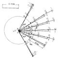
図3は、レバー1を水平な状態で且つ支点Cを位置調整部材7の長穴7aの最も上部に位置させた状態(初期位置、支点A,C間の垂直高さL)に設置して、レバー1に作用する下降力(5kg)と上昇力を平衡させて停止させたときのダンパー力の大きさと、この状態でレバー1を−60度(レバー1を支点Bが支点Aよりも下方に位置するように傾斜させた状態、下向きに60度)から+60度(レバー1を支点Bが支点Aよりも上方に位置するように傾斜させた状態、上向きに60度)まで回転させたとき、ダンパー6からレバー1に付与された上昇力とレバー1に作用する下降力との合成力を示すものである。
【0041】
図に於いて、レバー1が水平な状態で5kgの上昇力を付与し得るダンパー力は48.5kgであり、レバー1に前記ダンパー力を付与した状態で該レバー1を回転させたときに発生する合成力は、回転角度が下向きである場合プラスとなり、回転角度が上向きである場合マイナスとなる。
【0042】
ここで、合成力がプラスの場合レバー1には下降力が作用し、合成力がマイナスの場合レバー1には上昇力が作用する。従って、図3の例では、レバー1が水平な状態にあるとき下降力と上昇力とは平衡しているが、レバー1が下向きに回転した場合には下降力が大きくなり、レバー1が上向きに回転した場合には上昇力が大きくなる。
【0043】
次に、例えばレバー1を上向きに15度回転させたときに、ダンパー6による上昇力でレバー1を上向きに回転させ、これにより、機器3を上方に退避させようとする場合、レバー1が上向きに15度回転したときの合成力は、図に示すように0.31kgである。従って、支点A〜Cに於ける摩擦抵抗を調整して0.31kg、或いはこの値よりも僅かに小さい回転阻止力を発生させることで、レバー1が上向きに15度回転した状態、或いはその直前の状態まで、ダンパー6による上昇力の作用を阻止してレバー1を現在の位置に停止させることが可能となる。
【0044】
即ち、医師が機器3を上昇させたとしても、この上昇によってレバー1が上向き15度以下の回転で止まる場合、レバー1は現在の位置で停止した状態を維持することが可能となる。
【0045】
そして医師が機器3を上昇させてレバー1を上向きに15度以上回転させたとき、レバー1にはダンパー6との合成力と回転阻止力との差が上向きの回転力として作用し、この力に応じてレバー1が回転する。レバー1の回転角度が大きくなるのに伴って合成力も大きくなり、レバー1が機械的に設定される回転限界に到達したとき停止し、このとき、機器3は充分に高い位置に退避している。
【0046】
またレバー1を水平な状態とし、且つ支点Cを位置調整部材7の長穴7aに於ける最も上方の位置から下降させ(例えば初期位置から2.5cm,5cm下降させ)た状態でレバー1に作用する下降力(5kg)とダンパー6による上昇力を平衡させた場合、必要なダンパー力は図3のダンパー力よりも小さい値となる(図示せず)。
【0047】
図4は、図3の例に於けるレバー1の回転角度に対応して発生する合成力と、ダンパー6の支点Cの位置を図3の例よりも2.5cm、及び5cm下降させたとき、レバー1の回転角度に対応して発生する合成力とを比較したものである。図に示すように、ダンパー6の設置位置を調整することによって、レバー1の回転角度に応じて発生する合成力は図3に示す例よりも小さい値となる。また合成力の変化率も小さくなる。
【0048】
このことは、レバー1を特定の角度に設定した状態で下降力と上昇力とを平衡させたとき、ダンパー6の設置位置を調整することで、レバー1の回転角度に対応して発生する合成力の値を変化させることが可能であり、特に、ダンパー6の支点Cを支点Aから離隔させることで、発生する合成力の値を小さくすることが可能であることを示している。
【0049】
従って、ダンパー6の設置位置を調整して支点Cを支点Aから適当に離隔させることで、より小さい回転阻止力によってレバー1の停止状態を維持することが可能であり、医師が機器3を昇降させる際に必要な力を小さくすることが可能となる。特に5cm下降させた場合、広い角度範囲について小さい力で機器3を移動させることが可能である。
【0050】
次に、レバー1に作用する下降力と上昇力とを平衡させる際のレバー1の回転角度を変化させた場合について説明する。
【0051】
図5はレバー1が下向きに30度(−30度)回転した状態で且つ支点Cを初期位置に設置した状態で、下降力とダンパー6による上昇力を平衡させたときのダンパー力と、レバー1の回転角度に応じた合成力を示すものである。図に示すように、レバー1に作用する下降力が図3の例と同様に5kgであるにも関わらず、レバー1を平衡させるのに必要なダンパー力は57.86kgとなる。またレバー1を−30度から上向きに回転させると、該レバー1には上向きの合成力が作用し、下向きに回転させると下向きの合成力が作用することとなる。
【0052】
従って、図3の例と同様に、医師の姿勢に応じて機器3を退避させるべき高さを設定して、この高さに対応するレバー1の回転角度を設定し、この角度のとき、レバー1に作用する合成力に対抗させて、支点A〜Cに於ける摩擦抵抗を調整して回転阻止力を発生させることで、レバー1を停止させると共に停止状態を維持させることが可能である。
【0053】
尚、図3の例と図5の例を比較したとき、ダンパー6によるダンパー力が大幅に異なる。このため、1台の支持装置を用いた場合、発生し得るダンパー力が異なる2本のダンパー6を交換して対応することが好ましい。
【0054】
図6は、図5に於けるダンパー6を用いると共にレバー1を−30度で平衡させた状態で、ダンパー6の設置位置を変更(支点A,C間の垂直高さを初期位置+5cm)した場合のレバー1の回転角度に対応する合成力を示すものである。この場合、図5の例では平衡状態であった−30度であっても、レバー1に対するダンパー6の角度が変化したことに伴って平衡状態ではなくなり、上向きの合成力が発生している。
【0055】
図7は、図5に於けるダンパー6を用いると共にレバー1を−30度で平衡させた状態で、ダンパー6の設置位置を更に変更(支点A,C間の垂直高さを初期位置+10cm)した場合のレバー1の回転角度に対応する合成力を示すものである。この例ではレバー1は−60度〜+60度の全範囲で上向きの合成力が発生している。
【0056】
尚、図6,図7に示す例では、機器3を退避させるべき高さに応じた角度のレバー1に作用する上向きの合成力に対抗し得る回転阻止力を発生させるように支点A〜Cに於ける摩擦抵抗を調整することは前述の例と同様である。回転阻止力を発生させる場合、必ずしも全ての支点A〜C等に於ける摩擦抵抗を調整する必要はなく、支点A〜Cの中から選択された支点、例えば支点Bの摩擦抵抗のみを調整して回転阻止力を発生させるようにしても良い。
【0057】
図8は、図5〜図7に於けるレバー1の回転角度と合成力との関係を示すものである。図に示すように、ダンパー6のダンパー力を変化させることなく、且つレバー1に作用する下降力と上昇力とを平衡させた角度条件を変更することなく、ダンパー6の設置位置を変更することによって、レバー1の回転角度に対応して発生する合成力の値をより大きく変化させることが可能である。
【0058】
レバー1の平衡条件を設定した後、ダンパー6の設置位置を変更することで、より確実により広い範囲でレバー1(機器3)を停止させると共に停止状態を維持させることが可能である。
【0059】
上記実施例ではダンパーの設置位置を変えダンパー力を調整するには、支点AC間の高さを変えることで調整可能と説明したが、支点Bの位置を水平方向に変えること等でももちろん調整可能である。
【0060】
また、支点Aをはさんで支点Bの反対側の位置に重りを設けることでも上昇力を適宜調整することが可能である。
【0061】
更に、前記重りと、柱の長手方向(支点Aより上側にも柱を延長しても良い)、及び又は柱とレバーとをバネで接続し、調整することも可能である。
【0062】
【発明の効果】
以上詳細に説明したように本発明に係る支持装置では、レバーに上昇力を付与するダンパーを設け、該ダンパーによる上昇力とレバー1に作用する下降力との合成力と、回転阻止力とを調整することで、例えば顕微鏡等の機器を横臥した患者に接近させて診察,診療し、診察,診療が終了したとき、医師が機器を所定の高さに上昇させることによってレバーの回転角度が設定角度を越えたとき、該レバーに上向きの合成力が作用して、レバーを機器を上昇させて退避させる方向に回転させることが出来る。このため、医師が機器を所定の退避位置まで退避させることなく、該機器を退避させることが可能となり、医師の操作を容易とすることが出来る。
【図面の簡単な説明】
【図1】支持装置の全体構成を説明する図である。
【図2】支持装置の要部拡大図であり、レバーとダンパーとの関係を説明する図である。
【図3】レバーが水平なときに平衡させた後レバーの回転角度を変化させたときに変化する力を説明する図である。
【図4】図3の条件でダンパーの設置位置を変化させたときレバーの回転角度の変化に伴う力の変化を説明する図である。
【図5】レバーの回転角度が下向き30度のときに平衡させた後レバー角度の変化と力の変化を説明する図である。
【図6】図5の条件でダンパーの設置位置を変化させたとき変化する力を説明する図である。
【図7】図5の条件でダンパーの設置位置を変化させたとき変化する力を説明する図である。
【図8】図5〜図7の条件でレバーに作用する力の違いを説明する図である。
【符号の説明】
A〜C 支点
1 レバー
2 縦リンク
3 機器
4 柱
5 横リンク
6 ダンパー
6a ロッド
6b ピストン
6c シリンダー
7 位置調整部材
7a 長穴
8 軸受部材
9 アーム
10 回転支持部
11 ハンドル
12 ベース
13 スタンド
15 摺動部材
15a 長穴
15b 軸
16 ピン[0001]
BACKGROUND OF THE INVENTION
In the present invention, the device is brought close to a patient in a lying position during examination or treatment, and when the examination or treatment is completed, the device is separated from the patient so that it does not get in the way when the patient leaves the medical unit. The present invention relates to a support device for dental equipment.
[0002]
[Prior art]
During dental care or treatment, the patient remains in a lying position on the medical unit.
In this state, after medical treatment or medical examination (medical treatment) is performed, the patient gets up and leaves the medical treatment unit. In this way, it is peculiar to dental treatment that the patient stands up in the vicinity of the medical unit and lies on the side of the medical treatment.
[0003]
Recently, a microscope is sometimes used for medical treatment. Since this microscope is heavy and it is essential to maintain the position during medical treatment, it is generally supported by a predetermined support device.
[0004]
Such a support device is configured by attaching a column to a movable carriage, attaching a lever that can rotate about the vertical axis and the horizontal axis, and attaching a microscope to the tip of the lever. It is common. Further, the microscope is configured so that it can be moved to a desired position by a doctor and maintained in a stopped state at the moving position. The mechanism in the support device has a frictional resistance acting on each rotating part or a specific rotating part against the descent force according to the weight of the microscope, the gravity force of the lever and the distance from the rotating shaft. This is achieved by setting a large value.
[0005]
[Problems to be solved by the invention]
As described above, in the support device configured to maintain the position of the microscope by setting the frictional force in the rotating portion or the like to be larger than the downward force acting on the lever, when the microscope is moved, a human operation is required. It is essential. That is, when the medical care for the patient is completed and the patient stands up from the medical care unit, an operation of manually moving the microscope to the retracted position sufficiently separated from the medical care unit is essential. The operation of retracting the microscope to the retracted position is a cumbersome operation for a doctor who has completed medical care, and development of a support device that can retract the microscope from the medical care unit with a simpler operation is required.
[0006]
An object of the present invention is to provide a dental device supporting apparatus configured to rotate a lever by moving the device to a predetermined height, and when the rotation is above a preset range, the device is retracted by a damper. It is to provide.
[0007]
[Means for Solving the Problems]
In order to solve the above-described problems, a dental device support device according to the present invention is a dental device support device for bringing a device used for diagnosis or treatment closer to or away from a patient from above, with the device on one side. A lever that is mounted and rotatably supported on the other side via a rotation fulcrum, and a damper that applies a force to the lever in a direction to raise the side on which the device of the lever is mounted, the device, the lever, and the damper The combined force of the downward rotational force generated according to the gravity force and the distance from the rotation fulcrum and the upward rotational force generated according to the strength of the damper and the installation position of the damper, the lever and the lever The frictional resistance at each fulcrum of the member including the damper that rotates continuously with the rotation of the cylinder and the frictional resistance at the sliding part including the piston and cylinder of the damper that slides continuously with the rotation of the lever When the lever is in a predetermined angle range in the rotation angle of the lever, the combined force is smaller than the rotation prevention force to maintain the current angle, and when the lever is in a position above the angle range, It is set to rotate so that the combined force becomes larger than the rotation prevention force and the side on which the lever device is attached rises around the rotation fulcrum.
[0008]
In the above support device, a device used for diagnosis or medical treatment (for example, a tray equipped with a microscope, a lighting device, or a treatment device, hereinafter simply referred to as “device”) is attached to one side, and the other side is connected to a column or A damper is attached to a lever that is rotatably supported by a wall or the like, and the lever is always applied with a force in a direction in which the lever is lifted up about the rotation fulcrum, so that the lever The weight of the device acting on the lever, the weight of the lever, the weight of the damper and the downward rotating force according to the distance from the rotation fulcrum to the position where these forces act and the upward rotating force by the damper, or upward A downward rotational force acts.
[0009]
The upward rotational force acting on the lever is determined according to the force generated by the damper (damper force) and the angle of the damper with respect to the lever (the angle between the longitudinal direction of the lever and the axis of the damper). In other words, if the damper force is constant, this change will occur if the rotation angle of the lever changes. In Along with this, the angle of the damper with respect to the lever changes, and the upward rotational force acting on the lever changes accordingly.
[0010]
Therefore, by adjusting the installation position of the damper (for example, the mounting position of the rod with respect to the lever or the mounting position of the cylinder), the angle of the damper with respect to the lever can be changed. It is possible to change the upward rotational force acting on the.
[0011]
As described above, the upward rotational force acting on the lever can be set by adjusting the damper force and the damper installation position individually or simultaneously.
[0012]
The downward rotational force acting on the lever is set according to the distance from the rotation fulcrum of the lever to the device weight action line, lever weight action line, and damper weight action line. As the rotation angle of the lever changes, the distance from the rotation fulcrum of the lever to each of the action lines changes, but the change in the downward rotational force acting on the lever due to this change is not significant and is ignored. It is possible. Therefore, regardless of the rotation angle of the lever, the downward rotation force acting on the lever can be assumed to be constant.
[0013]
Therefore, when it is assumed that there is no friction acting on the rotation fulcrum, the downward rotation force acting on the lever and the upward rotation force are balanced by setting the damper force and the damper installation position individually or simultaneously. I can do it. This balanced state can be obtained by setting the damper force and the installation position of the damper according to the angle at which the lever is balanced. The balance state of the lever is limited to a preset angle range. When the lever deviates from the angle range, a downward rotational force or an upward rotational force acts on the lever.
[0014]
Therefore, the pistons of the dampers that slide continuously (slid along with the rotation of the lever) of each fulcrum of the member including the damper that rotates continuously with the rotation of the lever and the lever (rotate with the rotation of the lever) and the rotation of the lever By causing friction to act on the sliding part including the cylinder and the cylinder, this frictional resistance acts as a rotation-preventing force at the rotation fulcrum to counter the downward or upward rotational force acting on the lever. I can do it.
[0015]
By adjusting and setting the frictional force as appropriate, even if the lever deviates from the equilibrium range of the lever by setting the damper force and damper installation position, the lever is prevented from rotating and stopped. Can be maintained.
[0016]
Therefore, the angle range for stopping the lever can be set by appropriately adjusting the damper force, the installation position of the damper, and the various frictional forces, and the lever can be deviated from the angle range. The device can be rotated by applying an upward rotational force to the device so that the device can be raised and separated from the patient.
[0017]
DETAILED DESCRIPTION OF THE INVENTION
Hereinafter, preferred embodiments of the support device will be described with reference to the drawings. FIG. 1 is a diagram illustrating the overall configuration of the support device. FIG. 2 is an enlarged view of a main part of the support device, and is a view for explaining the relationship between the lever and the damper. FIG. 3 is a diagram illustrating the force that changes when the rotation angle of the lever is changed after equilibration when the lever is horizontal. FIG. 4 is a diagram for explaining a change in force accompanying a change in the rotation angle of the lever when the installation position of the damper is changed under the conditions of FIG. FIG. 5 is a diagram for explaining the change in lever angle and the change in force after equilibration when the rotation angle of the lever is 30 degrees downward. FIG. 6 is a diagram for explaining the force that changes when the installation position of the damper is changed under the conditions of FIG. FIG. 7 is a diagram for explaining the force that changes when the installation position of the damper is changed under the conditions of FIG. FIG. 8 is a diagram for explaining the difference in force acting on the lever under the conditions of FIGS.
[0018]
1 and 2, a
[0019]
Therefore, a parallel link is formed by the
[0020]
However, the support device does not necessarily have to be a parallel link, and can be constituted by only the
[0021]
On the
[0022]
Accordingly, when the rotation angle of the
[0023]
A
[0024]
In the
[0025]
In particular, a fulcrum C to which the cylinder 6c of the
[0026]
A long hole 7a is formed in the
[0027]
That is, when the
[0028]
Then, by adjusting the ascending force, it is possible to balance with the descending force acting on the fulcrum B, whereby the
[0029]
In this embodiment, the
[0030]
The fulcrums A to C of the
[0031]
Although it does not specifically limit as a structure for setting frictional resistance to a desired value, For example, the
[0032]
The
[0033]
In the above configuration, with the
[0034]
When the
[0035]
Next, an adjustment procedure for raising the
[0036]
That is, the height at which it is preferable to maintain the stopped state of the
[0037]
Moreover, it is preferable to provide a stopper so that the device does not fall too much when the device is moved downward. As this stopper, for example, a sliding
[0038]
Accordingly, when the
[0039]
Therefore, first, after removing the frictional resistance applied to the fulcrums A to C, the damper force of the
[0040]
FIG. 3 shows that the
[0041]
In the figure, the damper force that can give a lifting force of 5 kg when the
[0042]
Here, when the resultant force is positive, a downward force acts on the
[0043]
Next, for example, when the
[0044]
That is, even if the doctor raises the
[0045]
When the doctor raises the
[0046]
Further, the
[0047]
4 shows a case where the combined force generated corresponding to the rotation angle of the
[0048]
This is a composition that occurs in accordance with the rotation angle of the
[0049]
Therefore, by adjusting the installation position of the
[0050]
Next, the case where the rotation angle of the
[0051]
FIG. 5 shows a state where the
[0052]
Therefore, as in the example of FIG. 3, the height at which the
[0053]
When the example of FIG. 3 and the example of FIG. 5 are compared, the damper force by the
[0054]
FIG. 6 shows the state in which the
[0055]
7 further changes the installation position of the
[0056]
In the example shown in FIGS. 6 and 7, the fulcrums A to C are generated so as to generate a rotation preventing force that can counter the upward combined force acting on the
[0057]
FIG. 8 shows the relationship between the rotation angle of the
[0058]
By changing the installation position of the
[0059]
In the above embodiment, it was explained that adjusting the damper position by changing the installation position of the damper was possible by changing the height between the fulcrums AC, but of course it can also be adjusted by changing the position of the fulcrum B in the horizontal direction, etc. It is.
[0060]
Further, the lifting force can be adjusted as appropriate by providing a weight at a position opposite to the fulcrum B across the fulcrum A.
[0061]
Furthermore, the weight and the longitudinal direction of the column (the column may be extended above the fulcrum A) and / or the column and the lever may be connected by a spring for adjustment.
[0062]
【The invention's effect】
As described above in detail, in the support device according to the present invention, a damper that imparts a lifting force to the lever is provided, and a combined force of the lifting force by the damper and the descending force acting on the
[Brief description of the drawings]
FIG. 1 is a diagram illustrating an overall configuration of a support device.
FIG. 2 is an enlarged view of a main part of the support device, illustrating a relationship between a lever and a damper.
FIG. 3 is a diagram for explaining a force that changes when the rotation angle of the lever is changed after equilibration when the lever is horizontal;
4 is a diagram illustrating a change in force accompanying a change in the rotation angle of the lever when the installation position of the damper is changed under the conditions of FIG. 3; FIG.
FIG. 5 is a diagram for explaining a change in lever angle and a change in force after equilibration when the rotation angle of the lever is 30 degrees downward;
6 is a diagram for explaining a force that changes when the installation position of the damper is changed under the conditions of FIG. 5; FIG.
7 is a diagram for explaining a force that changes when the installation position of the damper is changed under the conditions of FIG. 5; FIG.
FIG. 8 is a diagram for explaining a difference in force acting on the lever under the conditions of FIGS.
[Explanation of symbols]
A to C fulcrum
1 Lever
2 Vertical links
3 Equipment
4 pillars
5 horizontal links
6 Damper
6a rod
6b Piston
6c cylinder
7 Position adjustment member
7a oblong hole
8 Bearing members
9 Arm
10 Rotation support
11 Handle
12 base
13 Stand
15 Sliding member
15a oblong hole
15b axis
16 pin
Claims (1)
Priority Applications (1)
| Application Number | Priority Date | Filing Date | Title |
|---|---|---|---|
| JP2000157201A JP4521576B2 (en) | 2000-05-26 | 2000-05-26 | Dental equipment support equipment |
Applications Claiming Priority (1)
| Application Number | Priority Date | Filing Date | Title |
|---|---|---|---|
| JP2000157201A JP4521576B2 (en) | 2000-05-26 | 2000-05-26 | Dental equipment support equipment |
Publications (3)
| Publication Number | Publication Date |
|---|---|
| JP2001333914A JP2001333914A (en) | 2001-12-04 |
| JP2001333914A5 JP2001333914A5 (en) | 2007-07-05 |
| JP4521576B2 true JP4521576B2 (en) | 2010-08-11 |
Family
ID=18661876
Family Applications (1)
| Application Number | Title | Priority Date | Filing Date |
|---|---|---|---|
| JP2000157201A Expired - Fee Related JP4521576B2 (en) | 2000-05-26 | 2000-05-26 | Dental equipment support equipment |
Country Status (1)
| Country | Link |
|---|---|
| JP (1) | JP4521576B2 (en) |
Families Citing this family (1)
| Publication number | Priority date | Publication date | Assignee | Title |
|---|---|---|---|---|
| DE102006051500A1 (en) * | 2006-10-31 | 2008-05-08 | Kaltenbach & Voigt Gmbh | Medical treatment device with a sensor handle |
Citations (4)
| Publication number | Priority date | Publication date | Assignee | Title |
|---|---|---|---|---|
| JPS6138571Y2 (en) * | 1983-03-31 | 1986-11-07 | ||
| JPH0747998B2 (en) * | 1989-07-04 | 1995-05-24 | ライカ アクチエンゲゼルシャフト | A pedestal for holding freely positionable instruments |
| JPH07184928A (en) * | 1993-12-28 | 1995-07-25 | Topcon Corp | Microscope for surgical operation |
| JPH11153293A (en) * | 1997-09-24 | 1999-06-08 | Carl Zeiss:Fa | Stand having energy accumulation part for weight balance |
-
2000
- 2000-05-26 JP JP2000157201A patent/JP4521576B2/en not_active Expired - Fee Related
Patent Citations (4)
| Publication number | Priority date | Publication date | Assignee | Title |
|---|---|---|---|---|
| JPS6138571Y2 (en) * | 1983-03-31 | 1986-11-07 | ||
| JPH0747998B2 (en) * | 1989-07-04 | 1995-05-24 | ライカ アクチエンゲゼルシャフト | A pedestal for holding freely positionable instruments |
| JPH07184928A (en) * | 1993-12-28 | 1995-07-25 | Topcon Corp | Microscope for surgical operation |
| JPH11153293A (en) * | 1997-09-24 | 1999-06-08 | Carl Zeiss:Fa | Stand having energy accumulation part for weight balance |
Also Published As
| Publication number | Publication date |
|---|---|
| JP2001333914A (en) | 2001-12-04 |
Similar Documents
| Publication | Publication Date | Title |
|---|---|---|
| US11413488B2 (en) | Exercise machine support system | |
| US9517375B2 (en) | Exercise machine support system | |
| US7461423B2 (en) | Device for supporting at least one arm of an operating person during a surgical operation | |
| US5662560A (en) | Bilateral weight unloading apparatus | |
| EP2949304B1 (en) | A rotating bed for medical care | |
| US7913335B2 (en) | High/low bed | |
| EP1908442A1 (en) | Device for adjusting the prestress of an elastic means around a predetermined tension or position | |
| US4277044A (en) | Mechanical counterbalance | |
| JP2005504605A (en) | Operating table | |
| KR20100119856A (en) | Surgery table appratus | |
| KR101682948B1 (en) | Shoulder joint tracking apparatus for upper-limb rehabilitation with gravity compensating mechanism | |
| JPS63256792A (en) | Apparatus for guiding roller of calender | |
| KR20140090840A (en) | Traction apparatus for rehabilitation training | |
| JP2002315759A (en) | Frame, especially for surgical microscope | |
| JP4521576B2 (en) | Dental equipment support equipment | |
| JPH07295677A (en) | Computer workstation | |
| US20230249022A1 (en) | Exercise Machine Support System | |
| CN112206477A (en) | Lower limb rehabilitation physiotherapy equipment | |
| JP2002191617A (en) | Stand, particularly for surgical microscope | |
| JP6225374B1 (en) | Bench press machine | |
| CN208339997U (en) | A kind of shoulder praises training aids | |
| CN205626355U (en) | Low limbs treatment riser | |
| JP6669865B2 (en) | Medical device holding device | |
| CN213788554U (en) | 3D dynamic balance rehabilitation physiotherapy bed | |
| JP2007261730A (en) | Workpiece holding device |
Legal Events
| Date | Code | Title | Description |
|---|---|---|---|
| A521 | Written amendment |
Free format text: JAPANESE INTERMEDIATE CODE: A523 Effective date: 20070523 |
|
| A621 | Written request for application examination |
Free format text: JAPANESE INTERMEDIATE CODE: A621 Effective date: 20070523 |
|
| TRDD | Decision of grant or rejection written | ||
| A01 | Written decision to grant a patent or to grant a registration (utility model) |
Free format text: JAPANESE INTERMEDIATE CODE: A01 Effective date: 20100420 |
|
| A01 | Written decision to grant a patent or to grant a registration (utility model) |
Free format text: JAPANESE INTERMEDIATE CODE: A01 |
|
| A61 | First payment of annual fees (during grant procedure) |
Free format text: JAPANESE INTERMEDIATE CODE: A61 Effective date: 20100506 |
|
| R150 | Certificate of patent or registration of utility model |
Free format text: JAPANESE INTERMEDIATE CODE: R150 |
|
| FPAY | Renewal fee payment (event date is renewal date of database) |
Free format text: PAYMENT UNTIL: 20130604 Year of fee payment: 3 |
|
| LAPS | Cancellation because of no payment of annual fees |