JP4517869B2 - Pedestrian protection device for vehicles - Google Patents
Pedestrian protection device for vehicles Download PDFInfo
- Publication number
- JP4517869B2 JP4517869B2 JP2005027195A JP2005027195A JP4517869B2 JP 4517869 B2 JP4517869 B2 JP 4517869B2 JP 2005027195 A JP2005027195 A JP 2005027195A JP 2005027195 A JP2005027195 A JP 2005027195A JP 4517869 B2 JP4517869 B2 JP 4517869B2
- Authority
- JP
- Japan
- Prior art keywords
- width direction
- vehicle width
- airbag
- vehicle
- case
- Prior art date
- Legal status (The legal status is an assumption and is not a legal conclusion. Google has not performed a legal analysis and makes no representation as to the accuracy of the status listed.)
- Expired - Fee Related
Links
Images


Description
本発明は、フロントガラスの前面側で展開するように構成されたエアバッグを有する車両用歩行者保護装置に関し、車両の安全技術の分野に属する。 The present invention relates to a vehicle pedestrian protection device having an airbag configured to be deployed on the front side of a windshield, and belongs to the field of vehicle safety technology.
フロントガラスの前面側で展開するように構成されたエアバッグを有する歩行者保護装置として、例えば、特許文献1には、該エアバッグが収容され、蓋部に破断部が設けられたケースをボンネットフードの下方に配設すると共に、該ボンネットフードにおける前記ケースの上方に位置する部分に開口部を設け、かつ該開口部に、エアバッグの展開圧力により押し開かれる扉部材を設けたものが開示されている。
As a pedestrian protection device having an airbag configured to be deployed on the front side of a windshield, for example,
ところで、このような歩行者保護装置のエアバッグは、迅速かつ確実に展開することが要求されるが、前記特許文献1に記載の歩行者保護装置の場合、エアバッグの展開時には、まず、ケースの蓋部の破断部を破断させ、その後さらに扉部材を押し開かねばならないので、エアバッグの展開に遅れが生じたり、エアバッグの展開の勢いが失われ、確実に展開しきらない虞がある。
By the way, although the airbag of such a pedestrian protection device is required to be deployed quickly and reliably, in the case of the pedestrian protection device described in
そこで、本発明は、フロントガラスの前面側で展開するように構成されたエアバッグの展開性を改善することができる車両用歩行者保護装置を提供することを課題とする。 Then, this invention makes it a subject to provide the pedestrian protection apparatus for vehicles which can improve the expandability of the airbag comprised so that it might expand | deploy on the front side of a windshield.
前記課題を解決するために、本発明は、次のように構成したことを特徴とする。 In order to solve the above-described problems, the present invention is configured as follows.
まず、本願の請求項1に記載の発明は、フロントガラスの前面側で展開するように構成されたエアバッグを有する車両用歩行者保護装置であって、前記エアバッグが収納されるケースは、車幅方向に延びる形状とされて、ボンネットフードの後端部近傍下方に配設されていると共に、該ケースの蓋部の一部である車幅方向両端部が、ボンネットフードの後端とフロントガラス下辺部との隙間を臨み、かつ、該蓋部における他の部分である車幅方向中間部よりも、前記エアバッグの展開圧力で容易に開かれるように脆弱とされていることを特徴とする。
First, the invention according to
また、請求項2に記載の発明は、前記請求項1に記載の発明において、前記ケースは前記蓋部と前記エアバッグが収納される収納部とを有し、該ケースの蓋部における前記収納部の上縁部の上方に位置する部分には、いずれも前記エアバッグの展開時に破断可能な溝部であって、該蓋部の前記車幅方向両端部と車幅方向中間部との境界に設けられた左右の境界の溝部と、これらの溝部間にわたって車幅方向に設けられた中間部の溝部と、前記左右の境界の溝部の車幅方向の外側にそれぞれ車幅方向に設けられた両端部の溝部とが設けられていると共に、これらの溝部のうち、左右の境界の溝部と両端部の溝部は中間部の溝部よりも深くされていることにより、前記蓋部における車幅方向両端部が車幅方向中間部よりも脆弱とされていることを特徴とする。 According to a second aspect of the present invention, in the first aspect of the present invention, the case includes the lid portion and a storage portion in which the airbag is stored, and the storage in the lid portion of the case. the portion located above the upper edge of the section, either a rupturable groove portion during deployment of the airbag, the boundary between the vehicle width direction end portions and the vehicle width direction intermediate portion of the lid portion The left and right boundary groove portions, the intermediate groove portion provided between the groove portions in the vehicle width direction, and both ends provided in the vehicle width direction outside the left and right boundary groove portions in the vehicle width direction, respectively. with groove parts and is provided, among these grooves, by the grooves of the groove and both end portions of the left and right boundaries that are deeper than the grooves of the intermediate portion, both vehicle transverse direction end portions of the lid portion the but it is fragile than the vehicle width direction intermediate portion And butterflies.
また、請求項3に記載の発明は、前記請求項1に記載の発明において、前記ケースの蓋部における車幅方向両端部は、該蓋部の車幅方向中間部よりも脆弱な材料で形成されていることにより、該蓋部の車幅方向両端部が車幅方向中間部よりも脆弱とされていることを特徴とする。
The invention according to
また、請求項4に記載の発明は、前記請求項1に記載の発明において、前記ケースの蓋部における車幅方向両端部は、該蓋部の車幅方向中間部よりも厚さが薄くされていることにより、該蓋部の車幅方向両端部が車幅方向中間部よりも脆弱とされていることを特徴とする。 According to a fourth aspect of the present invention, in the first aspect of the present invention, the both end portions in the vehicle width direction of the lid portion of the case are made thinner than the intermediate portion in the vehicle width direction of the lid portion. Therefore, both end portions in the vehicle width direction of the lid portion are made weaker than intermediate portions in the vehicle width direction .
さらに、請求項5に記載の発明は、前記請求項1から請求項4のいずれかに記載の発明において、前記エアバッグの展開時の車幅方向長は前記ケースの車幅方向長よりも長くされており、 かつ、該エアバッグは、車幅方向中間の中間部と、該中間部の両端からそれぞれ上方に延びる一対の端部とからなり、前記ケースへの収納時において、これら両端部が順次上方に重ねて折り畳まれた状態とされていることを特徴とする。
Furthermore, the invention according to claim 5 is the invention according to any one of
そして、請求項6に記載の発明は、前記請求項5に記載の発明において、前記エアバッグには、ガス発生器で発生したガスが前記両端部を経由して中間部に導入されるようにガス通路が形成されていることを特徴とする。 According to a sixth aspect of the invention, in the invention of the fifth aspect , the gas generated by the gas generator is introduced into the intermediate portion via the both end portions in the airbag. A gas passage is formed.
次に、本発明の効果について説明する。 Next, the effect of the present invention will be described.
まず、請求項1に記載の発明によれば、エアバッグを収納するケースの蓋部の車幅方向両端部がボンネットフードの後端とフロントガラス下辺部との隙間を臨み、かつ、該蓋部における車幅方向中間部よりも、前記エアバッグの展開圧力で容易に開かれるように脆弱とされているから、エアバッグは、まず、蓋部における車幅方向両端部を開いて展開し始めることとなる。その場合に、この上方には、エアバッグの更なる展開に対して障害となる物が存在しないので、この展開し始めた部分がボンネットフードに遮られることなく勢いよく展開し続けると共に、この勢いによりエアバッグの残りの部分の展開も促進されることとなり、この結果、エアバッグ全体が迅速かつ確実に展開することとなる。 First, according to the first aspect of the present invention, both end portions in the vehicle width direction of the lid portion of the case for housing the airbag face the gap between the rear end of the bonnet hood and the lower side portion of the windshield, and the lid portion Since the airbag is weaker than the middle portion in the vehicle width direction of the airbag so that it can be easily opened by the deployment pressure of the airbag, the airbag first starts to open by opening both ends in the vehicle width direction of the lid portion. It becomes. In that case, since there is no obstacle to the further deployment of the airbag above this, the portion that has started to deploy continues to be deployed vigorously without being blocked by the hood, and this momentum This also promotes the deployment of the remaining portion of the airbag, and as a result, the entire airbag is deployed quickly and reliably.
そして、請求項2から請求項4に記載の発明によれば、いずれによっても、蓋部における脆弱な部分を簡易な構成で実現することができる。
And according to invention of
ここで、前記エアバッグの車幅方向長は、フロントピラーを覆えるように、車幅よりも長くなる(つまり前記ケースの車幅方向長よりも長くなる)ことがあるが、この場合、エアバッグをケースに適切に収納しないと、エアバッグの展開性が損なわれてしまう。 Here, the vehicle width direction length of the air bag, as Ooeru the front pillar, (longer than the vehicle width direction length that is the case) become longer than the vehicle width that is, this case, air If the bag is not properly stored in the case, the deployability of the airbag is impaired.
しかし、請求項5に記載の発明によれば、エアバッグの中間部の両端側からそれぞれ上方に延びる一対の端部は、それぞれ順次上方に重ねて折り畳まれた状態で収納される、すなわち上方に展開しやすい状態で収納されるから、車幅方向長よりも長いエアバッグを用いた場合でも、エアバッグの展開性が損なわれることがない。 However, according to the fifth aspect of the present invention, the pair of end portions extending upward from the both end sides of the intermediate portion of the airbag are accommodated in a state of being sequentially folded and folded upward, that is, upward. Since it is stored in a state where it can be easily deployed, even when an airbag longer than the length in the vehicle width direction is used, the deployability of the airbag is not impaired.
また、請求項6に記載の発明によれば、エアバッグの展開の際、ガス発生器で発生したガスが前記エアバッグの両端部に優先的に導入されることにより、該エアバッグがまず両端部から上方に展開し始め、この展開圧力が、両端部の上方に位置する前記両ケースの端部の蓋部の脆弱とされている部分に作用することとなるので、エアバッグ全体の展開がより一層迅速かつ確実なものとなる。 According to the invention described in claim 6 , when the airbag is deployed, the gas generated by the gas generator is preferentially introduced into both end portions of the airbag, so that the airbag first has both ends. Since this deployment pressure will act on the weakened portions of the lids at the ends of the two cases located above both ends, the deployment of the entire airbag will begin. Even faster and more reliable.
以下、本発明を実施するための最良の形態について説明する。 Hereinafter, the best mode for carrying out the present invention will be described.
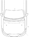
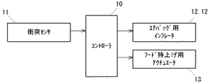
本発明に係る車両用歩行者保護装置は、図1に示す車両1に適用されている。該車両1には、図2に示すように、フロントガラス2の前面側で左右のフロントピラー3,3間にわたって展開可能なU字状のエアバッグ4が設けられている。また、この車両1には、図3に示すように、前記エアバッグ4の展開を制御するためのコントローラ10が設けられていると共に、車体前端部には、車体への歩行者等の衝突を検出するための衝突センサ11(例えばGセンサ)が設けられている。また、エアバッグ4の内部には該エアバッグ4展開用のガスを発生するインフレータ12,12が内臓されており(図10参照)、コントローラ10は、前記衝突センサ11から入力された信号が所定の条件に一致すると、インフレータ12,12に通電してガスを発生させ、エアバッグ4を展開させる。なお、前記衝突センサ11に代えてレーダや赤外線センサ等の衝突予知に用いることが可能なセンサをバンパ等に設けてもよく、この場合、該センサからの信号により衝突が予測される場合にインフレータ12,12に通電するようにすればよい。
The vehicle pedestrian protection apparatus according to the present invention is applied to a
次に、前記エアバッグ4が収納される車体前部の構造について説明する。すなわち、図4、図5に示すように、該車両1の前部には、ボンネットフード21により開閉されるエンジンルーム22が設けられていると共に、該エンジンルーム22の後端には該エンジンルーム22と車室23とを仕切るダッシュパネル24が配設されている。ダッシュパネル24上部におけるエンジンルーム22側の面には、車幅方向に延び、フロントガラス2の下辺部を支持するカウルメンバ25が設けられていると共に、該カウルメンバ25の上方には、車幅方向に延びる例えば樹脂材からなるカウルトップパネル26が配設されている。
Next, the structure of the front part of the vehicle body in which the
また、ボンネットフード21の後端部近傍下方には、前記エアバッグ4収納用のケース30が配設されている。このケース30は、図6にも併せて示すように、カウルメンバ25の前部の傾斜面25aに沿って車幅方向に延びて上面が開口し、エアバッグ4が収納される収納部31と、前記カウルトップパネル26における折曲部26aよりも車両前部側の部分からなる蓋部32とからなる。収納部31の後壁外面には複数のスタットボルト33…33が固着されており、該スタットボルト33…33がカウルメンバ25の前記傾斜面25aに設けられた取付孔25hに挿通されてナット34…34に螺合されている。また、蓋部32の前端壁及び収納部31の前壁に設けられた複数の孔部32h…32h,31h…31hに複数のリベット35…35が挿通され、これら両壁が圧着されている。
Further, a
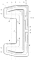
ここで、このケース30は、図1に示すように、平面視においては、車幅方向中間位置で車幅方向に延びる直線状形状の中間部30aと、該中間部30aの車幅方向両端側に所定の角度をなして接合された直線状形状の一対の端部30b,30bとで構成されており、収納部31の開口における車幅方向両端側部分が、ボンネットフード21の後端とフロントガラス2の下辺部との隙間を臨むように配設されている。
Here, as shown in FIG. 1, the
また、ケース30の蓋部32における前記収納部31の前記隙間に臨む部分のうち図1に格子状ハッチングで示す車幅方向両端側の部分32a,32aと、それ以外の部分32bとの境界部には、図7に示すように、蓋部32の裏面に、折曲部26aから折曲部26bまで延びる(図4、図5参照)溝部41,41が設けられている。また、図8、図9に示すように、蓋部32における折曲部26aの裏面には車幅に渡って溝部42が設けられている。これに対し、蓋部32における折曲部26bの裏面においては、左右の溝部41,41間にわたって溝部43が設けられていると共に、該溝部41,41の車幅方向外側には溝部44,44が設けられている。ここで、各溝部はいずれもV字状溝とされているが、各溝部の深さは、溝部41,44,44が最も深く、次いで溝部43が深く、次いで溝部42が深くされている。その場合に、溝部41,43,44,44は、エアバッグの展開圧で破断可能な深さとされているが、前述のように、溝部41,44,44の方が溝部43よりも深くされているので、内部から同一の展開圧が加わった場合でも、エアバッグの展開時には、まず溝部41,44,44が破断し、その後溝部43が破断することとなる。溝部42は、破断可能な深さとはされていないが、エアバッグ4の展開時に前記のように溝部41,43,44,44が破断したときに、蓋部32における折曲部26aと折曲部26bとの間の部分が該折曲部26aを中心として上方に回転可能なようにするためのものである。これによれば、エアバッグの展開時には、まず、蓋部32における折曲部26aと折曲部26bとの間の部分であって溝部41,41の車幅方向外側の部分32a,32a(以後、端部蓋部32a,32aという)が開き、次いで、折曲部26aと折曲部26bとの間の部分であって溝部41,41の車幅方向内側の部分32b(以後、中間蓋部32bという)が開くこととなる。
Further, of the portion of the
次に、エアバッグ4について詳しく説明すると、該エアバッグ4は、U字状の2枚の布材の周縁を縫合したものであり、図10に示すように、展開時にフロントガラス2の下辺部近傍を覆う中間部4aと、該中間部4aの両端からそれぞれ上方に延びてフロントピラー3,3を覆う一対の端部4b,4bとを有し、展開時の車幅方向長が前記ケース30の車幅方向長よりも長くされている。
Next, the
また、該エアバッグ4には一方の端部4bの上端部近傍から中間部4aを通って他方の端部4bの上端部近傍にまで延びる線状の縫合部4cが設けられ、該縫合部4cによりエアバッグ4内の空間が略上下2つの空間に分けられている。また、中間部4aにおける前記縫合部4cの下方には、該エアバッグ4を構成する2枚の布材がT字状に接合された接合部4dが設けられ、前記縫合部4cにより形成された下側の空間を左右に分断している。そして、この下側の空間の中央側に前述のインフレータ12,12が内臓されている。したがって、インフレータ12,12から発生したガスは、矢印ア、アで示すように、前記下側の空間から前記両端部4b,4bを経由して中間部4aの上側空間に導入されることとなる。換言すれば、この下側の空間は、前記前記両端部4b,4bを経由して中間部4aにおける上部側の空間にガスを導入するためのガス通路4eを構成している。
The
また、このエアバッグ4は、前述のように、車幅方向長がケース30の車幅方向長よりも長いので、図11に示すように、ケース30には折り畳まれた状態で収納されていると共に、インフレータ12,12に固着されたボルト36…36が収納部31の底板を貫通してナット37,37で固定されることにより、間接的にケース30に係止されている。
Further, as described above, since the length in the vehicle width direction is longer than the length in the vehicle width direction of the
ここで、ケース30への収納に際してのエアバッグ4の折り畳み方について説明しておく。すなわち、まず、図10に示す折れ線L1により順次上方に重ねて折り畳む(この折り畳んだ状態を図12、図13に示す)。次いで、両端部4b,4bを両端側から内側に折れ線L2により図13に仮想線で示すように折り畳み、図11に示すように順次上方に重ねて降り畳む。そして、このように折り畳んだ状態でケース30の収納部31に収容して前述のように固定する。なお、このように収容したとき、エアバッグ4の両端部4b,4bは、図11に示すように、それぞれ前記両ケース30の蓋部32の端部蓋部32a,32aの下方に位置する。
Here, how to fold the
次に、本実施の形態の作用について説明する。 Next, the operation of the present embodiment will be described.
まず、車両走行中に衝突センサ11により該車両1への歩行者の衝突が検知されると、前記インフレータ12,12に通電され、該インフレータ12,12からガスが発生することととなる。
First, when a collision of a pedestrian to the
その場合に、本実施の形態に係るエアバッグ4は、前述したように、インフレータ12,12で発生したガスが両端部4b,4bを経由してバッグ中間部4aに導入されるようにガス通路4eが形成されているので、まず両端部4b,4bが上方に膨張、展開し始め、その膨張圧力が端部蓋部32a,32aに作用することとなるが、このエアバッグ4の両端部4b,4b上方のケース30の端部蓋部32a,32aの溝部44,44は、、中間蓋部32bの溝部43よりも深くされている、つまり端部蓋部32a,32aが中間蓋部32bよりもエアバッグ4の展開圧力で容易に開くように脆弱とされているので、端部蓋部32a,32aの溝部44,44が中間蓋部32bの溝部43よりも先に破断して図14に示すようにまず端部蓋部32a,32aが開き、エアバッグ4の両端部4b,4bが中間部4aよりも先にケース30の外に展開し始めることととなる。
In that case, as described above, the
その場合に、本実施の形態においては、蓋部32における脆弱とされている部分である両端部蓋部32a,32aが、前述の図1に示すように、ボンネットフード4の後端とフロントガラス2下辺部との隙間を臨んで配設されている、すなわち、エアバッグ4における前記両端部蓋部32a,32aを開いて展開し始めた部分の更なる展開に対して障害となる物が存在しない位置に配設されているので、展開開始時の勢いがそがれることなく図15に示すように勢いよく展開し続けると共に、この展開中の両蓋部4b,4bの勢いにより中間部4aが両側から引き上げられて、図16に示すように中間蓋部32bが開き、かつ図17に示すように中間部4aの展開が促進され、エアバッグ4全体が迅速かつ確実に展開することとなる。
In this case, in the present embodiment, both
また、エアバッグ4のバッグ中間部4aの両端側からそれぞれ上方に延びる一対のバッグ端部4b,4bは、前述の図11に示すように、それぞれ順次上方に重ねて折り畳まれた状態で収納される、すなわち上方に展開しやすい状態で収納されるから、車幅方向長よりも長いエアバッグ4を用いた場合でも、エアバッグ4の展開性が損なわれることがない。
Further, the pair of
また、前記ケース30は、前述の図11に示すように、中間部30a及び両端部30b,30bがそれぞれ直線状形状で、両端部30b,30bが中間部30aに対して所定の角度をなして接合されたものであるから、円弧状のケースよりも生産が容易となるだけでなく、車体組付けの際の基準位置が明確となり、車体への組付性が向上する。また、ケース30の両端部30b,30bを、中間部30aとフロントガラス2との干渉を避けながら、ボンネット4の後端とフロントガラス2との隙間に位置させことが可能であるので、前述のような良好な展開性を得ることができる。
In addition, as shown in FIG. 11, the
また、蓋部32に溝部41,43,44,44を設けるだけで前記ケース30の蓋部32の一部を脆弱な構造とすることができる。
Further, a part of the
ここで、特許請求の範囲に記載の構成要素と本実施の形態の構成要素との対応について説明しておく。なお、後掲の符号の説明等により対応が明らかであるものについては省略する。すなわち、特許請求の範囲の請求項1における「エアバッグが収納されるケース」は実施の形態におけるケース30に対応し、「ケースの蓋部」はケース30の蓋部32に対応し、「ボンネットフードの後端とフロントガラス下辺部との隙間を臨み、かつ、該蓋部における他の部分よりも、前記エアバッグの展開圧力で容易に開かれるように脆弱とされているケースの蓋部の少なくとも一部」は端部蓋部32a,32aに対応する。また、請求項2における「エアバッグが収納される収納部」は実施の形態における収納部32に対応し、脆弱な部分の「溝部」は溝部44に対応し、それ以外の部分の「溝部」は溝部43に対応し、「第2の溝部」は溝部41に対応する。また、請求項6におけるエアバッグの「中間部」及び「一対の端部」はエアバッグ4の中間部4a及び端部4b,4bに対応する。また、請求項8におけるケースの「中間部」及び「一対の端部」はケース30の中間部30a及び端部30b,30bに対応する。
Here, the correspondence between the constituent elements described in the claims and the constituent elements of the present embodiment will be described. It should be noted that those whose correspondence is clear by the explanation of the reference numerals and the like described later are omitted. That is, the “case in which the airbag is stored” in
なお、前記実施の形態においては、前記蓋部32に溝部41,43,44,44を設けることにより、端部蓋部32a,32aを展開容易な脆弱構造としたが、本発明は、前記構造に限定されるものではなく、以下、ケースの蓋部が設けられたカウルトップパネルの構造を変更した他の形態についていくつか説明する。なお、カウルトップパネル以外は共通であり、その説明は省略する。
In the embodiment, the
すなわち、第2の実施の形態においては、図18に示すように、カウルトップパネル60の蓋部61に設けられた、第2の実施の形態に係る溝部41に相当する溝部62を折曲部60aから折曲部60bを越して蓋部61の前端壁にまで延長すると共に、該前端壁をこの溝部62の左右で分離したものである。これによれば、図19に示すように、まず溝部62が破断して端部蓋部61a,61aが開き、次いで、図20に示すように中間蓋部61bが開くこととなる。したがって、第2の実施の形態によれば、第1実施の形態同様簡易な構造で同様の効果が得られる。
That is, in the second embodiment, as shown in FIG. 18, a
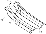
次に、第3の実施の形態について説明する。この第3の実施の形態は、請求項4に記載の発明に対応するもので、図21、図22に示すように、カウルトップパネル70の蓋部71の折曲部70a,70b間の端部蓋部71a,71aの厚さを中間蓋部71bよりも薄くし、これにより中間蓋部71bよりも脆弱としたものである。なお、両端部蓋部71aの周縁には、第1の実施の形態における溝部41,42,43,44に相当する溝部は不要である。これによれば、図23に示すように、まず、端部蓋部71a,71aが断裂して開き、次いで、図24に示すように中間蓋部71bが開くこととなる。したがって、第3の実施の形態によれば、第1実施の形態同様簡易な構造で同様の効果が得られる。
Next, a third embodiment will be described. The third embodiment corresponds to the invention described in
次に、第4の実施の形態について説明する。この第4の実施の形態は、請求項3に記載の発明に対応するもので、図25、図26に示すように、カウルトップパネル80の蓋部81の折曲部80a,80b間の端部蓋部81a,81aの材質を、中間蓋部81bよりも展開圧力により容易に破断しやすい脆弱なものとしたものである。この両端部蓋部81a,81aの材質としては、例えば、PPF(フィラー入りのポリプロピレン)、ポリエステル、TPO(オレフィン系熱可塑性エストラマー)、ポリエチレン等が挙げられる。なお、端部蓋部81a,81aの周縁には、第1の実施の形態における溝部41,42,43,44に相当する溝部は不要である。これによれば、図示は省略するが、第3の実施の形態同様、まず、端部蓋部81a,81aが断裂して開き、次いで、中間蓋部81bが開くこととなる。したがって、第4の実施の形態によれば、第1実施の形態同様簡易な構造で同様の効果が得られる。
Next, a fourth embodiment will be described. This fourth embodiment corresponds to the invention described in
次に、ケースの収納部の変形例について説明する。なお、これは請求項9に記載の発明に対応する。すなわち、図27に示すように、このケースの収納部31′の中間部31a′と両端部31b′,31b′との接合部には可撓性を有する蛇腹部31c′,31c′が設けられており、前記所定の角度が可変とされている。これによれば、車体及び(または)ケースの収納部31′に多少の寸法誤差があったとしても、この誤差を吸収しつつ車体に組み付けることができると共に、異なる車種にも適用することができるようになり、良好な展開性を実現することができる。
Next, a modification of the case storage portion will be described. This corresponds to the invention described in claim 9. That is, as shown in FIG. 27,
なお、エアバッグの展開がよりスムーズに実現されるように、図28、図29に示すように、ボンネットフード21の後部における車幅方向両端側に、該ボンネットフード21の後部側を持上げ可能なアクチュエータ13を設け、衝突センサ11で歩行者等の衝突が検出されたときに、該アクチュエータ13を作動させてボンネットフード21の後部側を持上げるようにしてもよい。なお、この場合においても、衝突センサ11に代えて衝突予知センサを設けてもよい。
In addition, as shown in FIG. 28 and FIG. 29, the rear side of the
本発明は、フロントガラスの前面側で展開するように構成されたエアバッグを有する車両用歩行者保護装置に広く適用することができる。 The present invention can be widely applied to a vehicle pedestrian protection device having an airbag configured to be deployed on the front side of a windshield.
1 車両
2 フロントガラス
3,3 フロントピラー
4 エアバッグ
4a エアバッグの中間部
4b,4b エアバッグの端部
4e,4e ガス通路
12,12 インフレータ(ガス発生器)
21 ボンネットフード
25 カウルメンバ
26,60,70,80 カウルトップパネル
30 ケース
30a ケースの中間部
30b,30b ケースの端部
31,31′ 収納部
32,61,71,81 蓋部
32a,32a,61a,61a,71a,71a,81a,81a 端部蓋部
32b,61b,71b,81b 中間蓋部
41 溝部(第2の溝部)
43 溝部(蓋部における脆弱な部分以外の溝部)
44,44, 溝部(蓋部における脆弱な部分の溝部)
DESCRIPTION OF
21
43 Groove (groove other than the fragile part of the lid)
44, 44, groove part (groove part of the weak part in the lid part)
Claims (6)
前記エアバッグが収納されるケースは、車幅方向に延びる形状とされて、ボンネットフードの後端部近傍下方に配設されていると共に、
該ケースの蓋部の一部である車幅方向両端部が、ボンネットフードの後端とフロントガラス下辺部との隙間を臨み、かつ、該蓋部における他の部分である車幅方向中間部よりも、前記エアバッグの展開圧力で容易に開かれるように脆弱とされていることを特徴とする車両用歩行者保護装置。 A vehicle pedestrian protection apparatus having an airbag configured to be deployed on the front side of a windshield,
The case in which the airbag is accommodated has a shape extending in the vehicle width direction, and is disposed near the rear end portion of the bonnet hood,
Both ends in the vehicle width direction, which are part of the lid of the case, face the gap between the rear end of the bonnet hood and the lower side of the windshield, and from the middle in the vehicle width direction, which is the other part of the lid Also, the vehicle pedestrian protection device is weak so that it can be easily opened by the deployment pressure of the airbag.
前記ケースは前記蓋部と前記エアバッグが収納される収納部とを有し、
該ケースの蓋部における前記収納部の上縁部の上方に位置する部分には、いずれも前記エアバッグの展開時に破断可能な溝部であって、該蓋部の前記車幅方向両端部と車幅方向中間部との境界に設けられた左右の境界の溝部と、これらの溝部間にわたって車幅方向に設けられた中間部の溝部と、前記左右の境界の溝部の車幅方向の外側にそれぞれ車幅方向に設けられた両端部の溝部とが設けられていると共に、
これらの溝部のうち、左右の境界の溝部と両端部の溝部は中間部の溝部よりも深くされていることにより、前記蓋部における車幅方向両端部が車幅方向中間部よりも脆弱とされていることを特徴とする車両用歩行者保護装置。 The vehicle pedestrian protection device according to claim 1,
The case has the lid portion and a storage portion in which the airbag is stored,
The portion located above the upper edge of the housing portion of the lid of the case, both a breakable groove portion during deployment of the airbag, the vehicle width direction end portions and car lid portion Left and right boundary groove portions provided at the boundary with the width direction intermediate portion, an intermediate portion groove portion provided between the groove portions in the vehicle width direction, and the left and right boundary groove portions on the outside in the vehicle width direction, respectively. While being provided with grooves at both ends provided in the vehicle width direction ,
Among these groove portions , the left and right boundary groove portions and the groove portions at both end portions are deeper than the intermediate groove portion, so that both end portions in the vehicle width direction of the lid portion are weaker than the intermediate portion in the vehicle width direction. A pedestrian protection device for a vehicle.
前記ケースの蓋部における車幅方向両端部は、該蓋部の車幅方向中間部よりも脆弱な材料で形成されていることにより、該蓋部の車幅方向両端部が車幅方向中間部よりも脆弱とされていることを特徴とする車両用歩行者保護装置。 The vehicle pedestrian protection device according to claim 1,
Both end portions in the vehicle width direction of the lid portion of the case are formed of a material weaker than the intermediate portion in the vehicle width direction of the lid portion, so that both end portions in the vehicle width direction of the lid portion are intermediate portions in the vehicle width direction. A pedestrian protection device for vehicles characterized by being made more fragile .
前記ケースの蓋部における車幅方向両端部は、該蓋部の車幅方向中間部よりも厚さが薄くされていることにより、該蓋部の車幅方向両端部が車幅方向中間部よりも脆弱とされていることを特徴とする車両用歩行者保護装置。 The vehicle pedestrian protection device according to claim 1,
Both ends in the vehicle width direction of the lid portion of the case are thinner than the intermediate portion in the vehicle width direction of the lid portion, so that both end portions in the vehicle width direction of the lid portion are closer to the vehicle width direction intermediate portion. Is a pedestrian protection device for vehicles.
前記エアバッグの展開時の車幅方向長は前記ケースの車幅方向長よりも長くされており、
かつ、該エアバッグは、車幅方向中間の中間部と、該中間部の両端からそれぞれ上方に延びる一対の端部とからなり、前記ケースへの収納時において、これら両端部がそれぞれ順次上方に重ねて折り畳まれた状態とされていることを特徴とする車両用歩行者保護装置。 The vehicle pedestrian protection device according to any one of claims 1 to 4,
The vehicle width direction length when the airbag is deployed is longer than the case width direction length of the case,
The airbag includes an intermediate portion in the middle in the vehicle width direction and a pair of end portions extending upward from both ends of the intermediate portion, and the both end portions are sequentially raised upward when stored in the case. A vehicle pedestrian protection device, characterized in that the vehicle is folded and folded .
前記エアバッグには、ガス発生器で発生したガスが前記両端部を経由して中間部に導入されるようにガス通路が形成されていることを特徴とする車両用歩行者保護装置。 The vehicle pedestrian protection device according to claim 5,
The vehicle pedestrian protection device according to claim 1, wherein a gas passage is formed in the airbag so that gas generated by a gas generator is introduced into the intermediate portion via both end portions .
Priority Applications (1)
| Application Number | Priority Date | Filing Date | Title |
|---|---|---|---|
| JP2005027195A JP4517869B2 (en) | 2005-02-03 | 2005-02-03 | Pedestrian protection device for vehicles |
Applications Claiming Priority (1)
| Application Number | Priority Date | Filing Date | Title |
|---|---|---|---|
| JP2005027195A JP4517869B2 (en) | 2005-02-03 | 2005-02-03 | Pedestrian protection device for vehicles |
Publications (3)
| Publication Number | Publication Date |
|---|---|
| JP2006213153A JP2006213153A (en) | 2006-08-17 |
| JP2006213153A5 JP2006213153A5 (en) | 2009-06-18 |
| JP4517869B2 true JP4517869B2 (en) | 2010-08-04 |
Family
ID=36976730
Family Applications (1)
| Application Number | Title | Priority Date | Filing Date |
|---|---|---|---|
| JP2005027195A Expired - Fee Related JP4517869B2 (en) | 2005-02-03 | 2005-02-03 | Pedestrian protection device for vehicles |
Country Status (1)
| Country | Link |
|---|---|
| JP (1) | JP4517869B2 (en) |
Cited By (1)
| Publication number | Priority date | Publication date | Assignee | Title |
|---|---|---|---|---|
| US20170008484A1 (en) * | 2014-02-19 | 2017-01-12 | Fuji Heavy Industries Ltd. | Airbag unit |
Families Citing this family (2)
| Publication number | Priority date | Publication date | Assignee | Title |
|---|---|---|---|---|
| JP2005138749A (en) * | 2003-11-07 | 2005-06-02 | Takata Corp | Device for protecting pedestrians and the like |
| WO2014120057A1 (en) * | 2013-02-04 | 2014-08-07 | Autoliv Development Ab | An airbag housing with weakened section |
Citations (5)
| Publication number | Priority date | Publication date | Assignee | Title |
|---|---|---|---|---|
| JPH0244552U (en) * | 1988-09-23 | 1990-03-27 | ||
| JP2002308028A (en) * | 2001-04-17 | 2002-10-23 | Mazda Motor Corp | Pedestrian protection device for vehicle |
| JP2003252140A (en) * | 2002-02-26 | 2003-09-10 | Toyoda Gosei Co Ltd | Air bag device for pedestrian |
| JP2003252144A (en) * | 2002-02-26 | 2003-09-10 | Toyoda Gosei Co Ltd | Air bag device for pedestrian |
| JP2004136813A (en) * | 2002-10-18 | 2004-05-13 | Toyoda Gosei Co Ltd | Airbag device for protecting pedestrian |
-
2005
- 2005-02-03 JP JP2005027195A patent/JP4517869B2/en not_active Expired - Fee Related
Patent Citations (5)
| Publication number | Priority date | Publication date | Assignee | Title |
|---|---|---|---|---|
| JPH0244552U (en) * | 1988-09-23 | 1990-03-27 | ||
| JP2002308028A (en) * | 2001-04-17 | 2002-10-23 | Mazda Motor Corp | Pedestrian protection device for vehicle |
| JP2003252140A (en) * | 2002-02-26 | 2003-09-10 | Toyoda Gosei Co Ltd | Air bag device for pedestrian |
| JP2003252144A (en) * | 2002-02-26 | 2003-09-10 | Toyoda Gosei Co Ltd | Air bag device for pedestrian |
| JP2004136813A (en) * | 2002-10-18 | 2004-05-13 | Toyoda Gosei Co Ltd | Airbag device for protecting pedestrian |
Cited By (2)
| Publication number | Priority date | Publication date | Assignee | Title |
|---|---|---|---|---|
| US20170008484A1 (en) * | 2014-02-19 | 2017-01-12 | Fuji Heavy Industries Ltd. | Airbag unit |
| US10286871B2 (en) * | 2014-02-19 | 2019-05-14 | Fuji Heavy Industries Ltd. | Airbag unit |
Also Published As
| Publication number | Publication date |
|---|---|
| JP2006213153A (en) | 2006-08-17 |
Similar Documents
| Publication | Publication Date | Title |
|---|---|---|
| US7556285B1 (en) | Airbag cover, instrument panel, airbag device and airbag casing | |
| JP5042552B2 (en) | Airbag cover, instrument panel, airbag device | |
| JP4285678B2 (en) | Airbag device for automobile | |
| US8870219B1 (en) | Foam-in-place interior panels having integrated airbag doors including substrates with airbag chute-door assemblies for motor vehicles | |
| JP4976315B2 (en) | Airbag cover, instrument panel, airbag device, airbag housing | |
| JP4535183B2 (en) | Knee airbag device for vehicle | |
| US7841441B2 (en) | Airbag apparatus | |
| JP4446901B2 (en) | Cover for airbag device and airbag device | |
| JP2006205889A5 (en) | ||
| US5375874A (en) | Air bag device for passenger's seat | |
| JP4517869B2 (en) | Pedestrian protection device for vehicles | |
| JP3405246B2 (en) | Installation structure of vehicle occupant protection system | |
| JP2006240558A (en) | Pedestrian crash protection device for vehicle | |
| JP2008149810A (en) | Airbag door structure | |
| JP4487870B2 (en) | Pedestrian protection device | |
| JP5209449B2 (en) | Interior parts for vehicles with airbag doors | |
| JP4242215B2 (en) | Cover for airbag device and airbag device | |
| JP4617225B2 (en) | Interior parts for vehicles with airbag doors | |
| JP3840933B2 (en) | Crew restraint system | |
| JP4672633B2 (en) | Airbag device | |
| JP4935646B2 (en) | Knee airbag device for vehicle | |
| JP2009220651A (en) | Front pillar structure of vehicle | |
| JP2007302209A (en) | Airbag structure | |
| JP6217213B2 (en) | Airbag door structure | |
| JP4426878B2 (en) | Airbag device for automobile |
Legal Events
| Date | Code | Title | Description |
|---|---|---|---|
| A621 | Written request for application examination |
Free format text: JAPANESE INTERMEDIATE CODE: A621 Effective date: 20071220 |
|
| A521 | Written amendment |
Free format text: JAPANESE INTERMEDIATE CODE: A523 Effective date: 20090428 |
|
| RD03 | Notification of appointment of power of attorney |
Free format text: JAPANESE INTERMEDIATE CODE: A7423 Effective date: 20090618 |
|
| A977 | Report on retrieval |
Free format text: JAPANESE INTERMEDIATE CODE: A971007 Effective date: 20091228 |
|
| A131 | Notification of reasons for refusal |
Free format text: JAPANESE INTERMEDIATE CODE: A131 Effective date: 20100119 |
|
| A521 | Written amendment |
Free format text: JAPANESE INTERMEDIATE CODE: A523 Effective date: 20100318 |
|
| TRDD | Decision of grant or rejection written | ||
| A01 | Written decision to grant a patent or to grant a registration (utility model) |
Free format text: JAPANESE INTERMEDIATE CODE: A01 Effective date: 20100427 |
|
| A01 | Written decision to grant a patent or to grant a registration (utility model) |
Free format text: JAPANESE INTERMEDIATE CODE: A01 |
|
| A61 | First payment of annual fees (during grant procedure) |
Free format text: JAPANESE INTERMEDIATE CODE: A61 Effective date: 20100510 |
|
| FPAY | Renewal fee payment (event date is renewal date of database) |
Free format text: PAYMENT UNTIL: 20130528 Year of fee payment: 3 |
|
| R150 | Certificate of patent or registration of utility model |
Ref document number: 4517869 Country of ref document: JP Free format text: JAPANESE INTERMEDIATE CODE: R150 Free format text: JAPANESE INTERMEDIATE CODE: R150 |
|
| FPAY | Renewal fee payment (event date is renewal date of database) |
Free format text: PAYMENT UNTIL: 20140528 Year of fee payment: 4 |
|
| LAPS | Cancellation because of no payment of annual fees |