JP4285678B2 - Airbag device for automobile - Google Patents
Airbag device for automobile Download PDFInfo
- Publication number
- JP4285678B2 JP4285678B2 JP2002228758A JP2002228758A JP4285678B2 JP 4285678 B2 JP4285678 B2 JP 4285678B2 JP 2002228758 A JP2002228758 A JP 2002228758A JP 2002228758 A JP2002228758 A JP 2002228758A JP 4285678 B2 JP4285678 B2 JP 4285678B2
- Authority
- JP
- Japan
- Prior art keywords
- opening
- fracture
- reinforcing
- airbag
- frame body
- Prior art date
- Legal status (The legal status is an assumption and is not a legal conclusion. Google has not performed a legal analysis and makes no representation as to the accuracy of the status listed.)
- Expired - Lifetime
Links
- 230000002787 reinforcement Effects 0.000 claims abstract description 57
- 230000003014 reinforcing effect Effects 0.000 claims description 164
- 238000003466 welding Methods 0.000 claims description 38
- 239000000463 material Substances 0.000 claims description 18
- 229920003002 synthetic resin Polymers 0.000 claims description 18
- 239000000057 synthetic resin Substances 0.000 claims description 18
- 229920005992 thermoplastic resin Polymers 0.000 claims description 9
- 238000003825 pressing Methods 0.000 claims description 5
- 229920006124 polyolefin elastomer Polymers 0.000 claims description 2
- 238000005452 bending Methods 0.000 claims 3
- 230000002093 peripheral effect Effects 0.000 description 9
- 229920005989 resin Polymers 0.000 description 6
- 239000011347 resin Substances 0.000 description 6
- 239000002184 metal Substances 0.000 description 5
- 239000004743 Polypropylene Substances 0.000 description 4
- 230000000694 effects Effects 0.000 description 4
- 150000001336 alkenes Chemical class 0.000 description 3
- 229920001971 elastomer Polymers 0.000 description 3
- 239000000806 elastomer Substances 0.000 description 3
- 238000003754 machining Methods 0.000 description 3
- 238000012986 modification Methods 0.000 description 3
- 230000004048 modification Effects 0.000 description 3
- JRZJOMJEPLMPRA-UHFFFAOYSA-N olefin Natural products CCCCCCCC=C JRZJOMJEPLMPRA-UHFFFAOYSA-N 0.000 description 3
- -1 polypropylene Polymers 0.000 description 3
- 229920001155 polypropylene Polymers 0.000 description 3
- 238000004064 recycling Methods 0.000 description 3
- 230000002411 adverse Effects 0.000 description 2
- 238000005336 cracking Methods 0.000 description 2
- 238000003801 milling Methods 0.000 description 2
- 238000000465 moulding Methods 0.000 description 2
- 239000000088 plastic resin Substances 0.000 description 2
- 239000002440 industrial waste Substances 0.000 description 1
- 238000001746 injection moulding Methods 0.000 description 1
- 238000009434 installation Methods 0.000 description 1
- 238000005304 joining Methods 0.000 description 1
- 238000000034 method Methods 0.000 description 1
- 239000004033 plastic Substances 0.000 description 1
- 239000002994 raw material Substances 0.000 description 1
- 238000010079 rubber tapping Methods 0.000 description 1
- 238000000926 separation method Methods 0.000 description 1
- 239000012815 thermoplastic material Substances 0.000 description 1
Images


Classifications
-
- B—PERFORMING OPERATIONS; TRANSPORTING
- B29—WORKING OF PLASTICS; WORKING OF SUBSTANCES IN A PLASTIC STATE IN GENERAL
- B29C—SHAPING OR JOINING OF PLASTICS; SHAPING OF MATERIAL IN A PLASTIC STATE, NOT OTHERWISE PROVIDED FOR; AFTER-TREATMENT OF THE SHAPED PRODUCTS, e.g. REPAIRING
- B29C65/00—Joining or sealing of preformed parts, e.g. welding of plastics materials; Apparatus therefor
- B29C65/02—Joining or sealing of preformed parts, e.g. welding of plastics materials; Apparatus therefor by heating, with or without pressure
- B29C65/06—Joining or sealing of preformed parts, e.g. welding of plastics materials; Apparatus therefor by heating, with or without pressure using friction, e.g. spin welding
-
- B—PERFORMING OPERATIONS; TRANSPORTING
- B29—WORKING OF PLASTICS; WORKING OF SUBSTANCES IN A PLASTIC STATE IN GENERAL
- B29C—SHAPING OR JOINING OF PLASTICS; SHAPING OF MATERIAL IN A PLASTIC STATE, NOT OTHERWISE PROVIDED FOR; AFTER-TREATMENT OF THE SHAPED PRODUCTS, e.g. REPAIRING
- B29C66/00—General aspects of processes or apparatus for joining preformed parts
- B29C66/01—General aspects dealing with the joint area or with the area to be joined
- B29C66/05—Particular design of joint configurations
- B29C66/10—Particular design of joint configurations particular design of the joint cross-sections
- B29C66/11—Joint cross-sections comprising a single joint-segment, i.e. one of the parts to be joined comprising a single joint-segment in the joint cross-section
- B29C66/112—Single lapped joints
- B29C66/1122—Single lap to lap joints, i.e. overlap joints
-
- B—PERFORMING OPERATIONS; TRANSPORTING
- B29—WORKING OF PLASTICS; WORKING OF SUBSTANCES IN A PLASTIC STATE IN GENERAL
- B29C—SHAPING OR JOINING OF PLASTICS; SHAPING OF MATERIAL IN A PLASTIC STATE, NOT OTHERWISE PROVIDED FOR; AFTER-TREATMENT OF THE SHAPED PRODUCTS, e.g. REPAIRING
- B29C66/00—General aspects of processes or apparatus for joining preformed parts
- B29C66/01—General aspects dealing with the joint area or with the area to be joined
- B29C66/05—Particular design of joint configurations
- B29C66/10—Particular design of joint configurations particular design of the joint cross-sections
- B29C66/11—Joint cross-sections comprising a single joint-segment, i.e. one of the parts to be joined comprising a single joint-segment in the joint cross-section
- B29C66/114—Single butt joints
-
- B—PERFORMING OPERATIONS; TRANSPORTING
- B29—WORKING OF PLASTICS; WORKING OF SUBSTANCES IN A PLASTIC STATE IN GENERAL
- B29C—SHAPING OR JOINING OF PLASTICS; SHAPING OF MATERIAL IN A PLASTIC STATE, NOT OTHERWISE PROVIDED FOR; AFTER-TREATMENT OF THE SHAPED PRODUCTS, e.g. REPAIRING
- B29C66/00—General aspects of processes or apparatus for joining preformed parts
- B29C66/01—General aspects dealing with the joint area or with the area to be joined
- B29C66/05—Particular design of joint configurations
- B29C66/10—Particular design of joint configurations particular design of the joint cross-sections
- B29C66/13—Single flanged joints; Fin-type joints; Single hem joints; Edge joints; Interpenetrating fingered joints; Other specific particular designs of joint cross-sections not provided for in groups B29C66/11 - B29C66/12
- B29C66/131—Single flanged joints, i.e. one of the parts to be joined being rigid and flanged in the joint area
-
- B—PERFORMING OPERATIONS; TRANSPORTING
- B29—WORKING OF PLASTICS; WORKING OF SUBSTANCES IN A PLASTIC STATE IN GENERAL
- B29C—SHAPING OR JOINING OF PLASTICS; SHAPING OF MATERIAL IN A PLASTIC STATE, NOT OTHERWISE PROVIDED FOR; AFTER-TREATMENT OF THE SHAPED PRODUCTS, e.g. REPAIRING
- B29C66/00—General aspects of processes or apparatus for joining preformed parts
- B29C66/01—General aspects dealing with the joint area or with the area to be joined
- B29C66/05—Particular design of joint configurations
- B29C66/302—Particular design of joint configurations the area to be joined comprising melt initiators
- B29C66/3022—Particular design of joint configurations the area to be joined comprising melt initiators said melt initiators being integral with at least one of the parts to be joined
- B29C66/30223—Particular design of joint configurations the area to be joined comprising melt initiators said melt initiators being integral with at least one of the parts to be joined said melt initiators being rib-like
-
- B—PERFORMING OPERATIONS; TRANSPORTING
- B29—WORKING OF PLASTICS; WORKING OF SUBSTANCES IN A PLASTIC STATE IN GENERAL
- B29C—SHAPING OR JOINING OF PLASTICS; SHAPING OF MATERIAL IN A PLASTIC STATE, NOT OTHERWISE PROVIDED FOR; AFTER-TREATMENT OF THE SHAPED PRODUCTS, e.g. REPAIRING
- B29C66/00—General aspects of processes or apparatus for joining preformed parts
- B29C66/50—General aspects of joining tubular articles; General aspects of joining long products, i.e. bars or profiled elements; General aspects of joining single elements to tubular articles, hollow articles or bars; General aspects of joining several hollow-preforms to form hollow or tubular articles
- B29C66/51—Joining tubular articles, profiled elements or bars; Joining single elements to tubular articles, hollow articles or bars; Joining several hollow-preforms to form hollow or tubular articles
- B29C66/53—Joining single elements to tubular articles, hollow articles or bars
- B29C66/532—Joining single elements to the wall of tubular articles, hollow articles or bars
-
- B—PERFORMING OPERATIONS; TRANSPORTING
- B29—WORKING OF PLASTICS; WORKING OF SUBSTANCES IN A PLASTIC STATE IN GENERAL
- B29C—SHAPING OR JOINING OF PLASTICS; SHAPING OF MATERIAL IN A PLASTIC STATE, NOT OTHERWISE PROVIDED FOR; AFTER-TREATMENT OF THE SHAPED PRODUCTS, e.g. REPAIRING
- B29C66/00—General aspects of processes or apparatus for joining preformed parts
- B29C66/50—General aspects of joining tubular articles; General aspects of joining long products, i.e. bars or profiled elements; General aspects of joining single elements to tubular articles, hollow articles or bars; General aspects of joining several hollow-preforms to form hollow or tubular articles
- B29C66/51—Joining tubular articles, profiled elements or bars; Joining single elements to tubular articles, hollow articles or bars; Joining several hollow-preforms to form hollow or tubular articles
- B29C66/54—Joining several hollow-preforms, e.g. half-shells, to form hollow articles, e.g. for making balls, containers; Joining several hollow-preforms, e.g. half-cylinders, to form tubular articles
-
- B—PERFORMING OPERATIONS; TRANSPORTING
- B29—WORKING OF PLASTICS; WORKING OF SUBSTANCES IN A PLASTIC STATE IN GENERAL
- B29C—SHAPING OR JOINING OF PLASTICS; SHAPING OF MATERIAL IN A PLASTIC STATE, NOT OTHERWISE PROVIDED FOR; AFTER-TREATMENT OF THE SHAPED PRODUCTS, e.g. REPAIRING
- B29C66/00—General aspects of processes or apparatus for joining preformed parts
- B29C66/70—General aspects of processes or apparatus for joining preformed parts characterised by the composition, physical properties or the structure of the material of the parts to be joined; Joining with non-plastics material
- B29C66/73—General aspects of processes or apparatus for joining preformed parts characterised by the composition, physical properties or the structure of the material of the parts to be joined; Joining with non-plastics material characterised by the intensive physical properties of the material of the parts to be joined, by the optical properties of the material of the parts to be joined, by the extensive physical properties of the parts to be joined, by the state of the material of the parts to be joined or by the material of the parts to be joined being a thermoplastic or a thermoset
- B29C66/739—General aspects of processes or apparatus for joining preformed parts characterised by the composition, physical properties or the structure of the material of the parts to be joined; Joining with non-plastics material characterised by the intensive physical properties of the material of the parts to be joined, by the optical properties of the material of the parts to be joined, by the extensive physical properties of the parts to be joined, by the state of the material of the parts to be joined or by the material of the parts to be joined being a thermoplastic or a thermoset characterised by the material of the parts to be joined being a thermoplastic or a thermoset
- B29C66/7392—General aspects of processes or apparatus for joining preformed parts characterised by the composition, physical properties or the structure of the material of the parts to be joined; Joining with non-plastics material characterised by the intensive physical properties of the material of the parts to be joined, by the optical properties of the material of the parts to be joined, by the extensive physical properties of the parts to be joined, by the state of the material of the parts to be joined or by the material of the parts to be joined being a thermoplastic or a thermoset characterised by the material of the parts to be joined being a thermoplastic or a thermoset characterised by the material of at least one of the parts being a thermoplastic
-
- B—PERFORMING OPERATIONS; TRANSPORTING
- B60—VEHICLES IN GENERAL
- B60R—VEHICLES, VEHICLE FITTINGS, OR VEHICLE PARTS, NOT OTHERWISE PROVIDED FOR
- B60R21/00—Arrangements or fittings on vehicles for protecting or preventing injuries to occupants or pedestrians in case of accidents or other traffic risks
- B60R21/02—Occupant safety arrangements or fittings, e.g. crash pads
- B60R21/16—Inflatable occupant restraints or confinements designed to inflate upon impact or impending impact, e.g. air bags
- B60R21/20—Arrangements for storing inflatable members in their non-use or deflated condition; Arrangement or mounting of air bag modules or components
- B60R21/215—Arrangements for storing inflatable members in their non-use or deflated condition; Arrangement or mounting of air bag modules or components characterised by the covers for the inflatable member
- B60R21/2165—Arrangements for storing inflatable members in their non-use or deflated condition; Arrangement or mounting of air bag modules or components characterised by the covers for the inflatable member characterised by a tear line for defining a deployment opening
-
- B—PERFORMING OPERATIONS; TRANSPORTING
- B29—WORKING OF PLASTICS; WORKING OF SUBSTANCES IN A PLASTIC STATE IN GENERAL
- B29K—INDEXING SCHEME ASSOCIATED WITH SUBCLASSES B29B, B29C OR B29D, RELATING TO MOULDING MATERIALS OR TO MATERIALS FOR MOULDS, REINFORCEMENTS, FILLERS OR PREFORMED PARTS, e.g. INSERTS
- B29K2101/00—Use of unspecified macromolecular compounds as moulding material
- B29K2101/12—Thermoplastic materials
-
- B—PERFORMING OPERATIONS; TRANSPORTING
- B29—WORKING OF PLASTICS; WORKING OF SUBSTANCES IN A PLASTIC STATE IN GENERAL
- B29L—INDEXING SCHEME ASSOCIATED WITH SUBCLASS B29C, RELATING TO PARTICULAR ARTICLES
- B29L2031/00—Other particular articles
- B29L2031/30—Vehicles, e.g. ships or aircraft, or body parts thereof
- B29L2031/3005—Body finishings
- B29L2031/3038—Air bag covers
-
- B—PERFORMING OPERATIONS; TRANSPORTING
- B60—VEHICLES IN GENERAL
- B60R—VEHICLES, VEHICLE FITTINGS, OR VEHICLE PARTS, NOT OTHERWISE PROVIDED FOR
- B60R21/00—Arrangements or fittings on vehicles for protecting or preventing injuries to occupants or pedestrians in case of accidents or other traffic risks
- B60R21/02—Occupant safety arrangements or fittings, e.g. crash pads
- B60R21/16—Inflatable occupant restraints or confinements designed to inflate upon impact or impending impact, e.g. air bags
- B60R21/20—Arrangements for storing inflatable members in their non-use or deflated condition; Arrangement or mounting of air bag modules or components
- B60R21/217—Inflation fluid source retainers, e.g. reaction canisters; Connection of bags, covers, diffusers or inflation fluid sources therewith or together
- B60R2021/2172—Inflation fluid source retainers, e.g. reaction canisters; Connection of bags, covers, diffusers or inflation fluid sources therewith or together the cover being connected to the surrounding part and to the module, e.g. floating mounts
-
- B—PERFORMING OPERATIONS; TRANSPORTING
- B60—VEHICLES IN GENERAL
- B60R—VEHICLES, VEHICLE FITTINGS, OR VEHICLE PARTS, NOT OTHERWISE PROVIDED FOR
- B60R21/00—Arrangements or fittings on vehicles for protecting or preventing injuries to occupants or pedestrians in case of accidents or other traffic risks
- B60R21/02—Occupant safety arrangements or fittings, e.g. crash pads
- B60R21/16—Inflatable occupant restraints or confinements designed to inflate upon impact or impending impact, e.g. air bags
- B60R21/20—Arrangements for storing inflatable members in their non-use or deflated condition; Arrangement or mounting of air bag modules or components
- B60R21/205—Arrangements for storing inflatable members in their non-use or deflated condition; Arrangement or mounting of air bag modules or components in dashboards
Abstract
Description
【0001】
【発明の属する技術分野】
本発明は、自動車などの車両の衝突時に助手席や運転席等の車内にいる乗員を正面衝突や側面衝突の衝撃から保護して、乗員の安全性を確保するための自動車用エアーバッグ装置に係り、特に補強部材の取付構造の改良に関するものである。
【0002】
【従来の技術】
自動車などの車両に適用される助手席用,運転席用及び左右側柱用等のエアーバッグ装置は、基本的に、エアーバッグと、このエアーバッグを折り畳んだ状態で収容するエアーバッグケースと、エアーバッグを膨張展開するインフレータを備え、このエアーバッグ装置は車両内装パネルの内側に配設される構成になっている。
そして、自動車の内装パネルは、一般的にポリプロピレン樹脂等のプラスチック樹脂材により一体成形されたパネルコアーの表面を覆うポリプロピレン樹脂等のプラスチック樹脂製のインストルメントパネルから構成される。
【0003】
従来の自動車用エアーバッグ装置は、図1及び図2に示すような破断開放部の破断溝を見えにくくしたシームレスタイプの助手席用エアーバッグ装置が提供されている。
即ち、図1及び図2において、内装パネル10には、図示しないレーザ発生手段からパルス状に発生するレーザを、内装パネル10の裏面側からその裏面に固着する一対の金属製の板材料を折曲成形した補強板材11,11の外形縁部に沿って相対移動しながら照射することにより、内装パネル10の裏面に対して直角方向に形成された長尺方向の前,後ヒンジ溝10aと中央破断溝10b及び短尺方向の破断用溝10cを設けることで、エアーバッグ12を収容するエアーバッグケース13の開口13aの大きさに対応するエアーバッグ膨張展開用の破断開放部14が形成されている。
また、前記破断開放部14は長尺方向に形成した中央破断用溝10b,短尺の左右破断溝10c、10cによって、前,後破断開放部15a,15bとなりエアーバッグ膨張展開時に、それぞれ前記前,後ヒンジ溝10a,10aを介して観音開き状態に破断開口される構成になっている。
【0004】
前記内装パネル10の破断開放部14は、エアーバッグ膨張展開時にエアーバッグ12の展開圧力により開放される際、前記前,後ヒンジ溝10aが前記内装パネル10より切り離されてしまう場合がある。そのため前記内装パネル10の前記破断開放部14の裏面には、前記一対の補強板材11,11の一端水平部11a,11aが溶着等の手段によりカシメ固着され、その各他端となる鉛直部11b,11bが、ヒンジ部11c,11cを介して折り曲げられて垂下され、この各鉛直部11b,11bを、前記エアーバッグケース13の開口部13aの外周寸法より僅かに大きな内周寸法を有するようにして前記内装パネル10の裏面に一体成形された枠状の補強リブ16の前,後壁とともに、前記ケース13の前,後壁面13b,13bに取り付けられたフック部17に係止する構成とすることで、エアーバッグ膨張展開時に観音開きされた内装パネル10の破断開放部14が飛散しないようにしたものである。
なお、前記前,後破断開放部15a,15bの開放を阻害しないようにするため、前記一対の補強板材11,11の各他端の鉛直部11b,11bのフック係止用穴11d,11dは大きめに設定されており、前記前,後破断開放部15a,15bの開放と共に、前記各鉛直部11b,11bの上方への移動を可能にし、エアーバッグ膨張展開時の展開圧力を吸収できるようにしている。
【0005】
上記のように構成された自動車用エアーバッグ装置においては、車両が衝突した際には、その衝突時の衝撃力をセンサで検出し、このセンサで検出した衝撃力が予め定めた値以上になった否かをCPU等からなる制御装置で判定し、設定値以上と判定された時に制御装置から出力される信号によりインフレータを動作させて所定のガスを発生させ、このガスをエアーバッグに供給することにより、エアーバッグを急速に膨張展開させる。
【0006】
すなわち、エアーバッグが膨張展開することにより、その圧力で内装パネル10の破断開放部14が内側から押圧されると、破断開放部14の破断用溝10b,10cが破断され、前,後ヒンジ溝10aを介して観音開き状態に展開される。そして、観音開き状態に展開された前,後破断開放部15a,15bは各補強板材11,11のそれぞれのヒンジ部11c,11cを介して展開される。
これと同時に、エアーバッグ12は開かれた破断開放部14から内装パネル10の外方へ膨張展開され、この膨張展開されたエアーバッグ12の緩衝作用で、助手席の乗員の頭部或いは胸部等を支えることにより、乗員を車両衝突時の衝撃力から保護するようにしている。
【0007】
【発明が解決しようとする課題】
ところで、上記の自動車用エアーバッグ装置においては、内装パネル10の破断開放部14が設けられている開口周縁の下方裏面には補強板材11,11や補強リブ16が設けられているものの、これら補強板材11,11や補強リブ16は、エアーバッグケース13の組付性や前,後破断開放部15a,15bの開放容易性のため、フック部17との係合角穴に上下方向にガタが設けられており、内装パネル10の上面すなわち表面側からの押圧力を支持する構造にはなっておらず、乗車中に誤って上面より内装パネル10に負荷を掛けると前,後ヒンジ溝10a,10aや中央破断溝10bおよび破断溝10c,10cが破断されてしまう等、破断開放部14が凹状にへこんだり、開口周縁が変形したりして内装パネル10の外観が損なわれるという問題点がある。
また、エアーバッグ装置の作動時に、エアーバッグ膨張初期に、補強リブ16の内側が外に押され、内装パネル10の破断開口部縁のコーナーに割れが発生し、飛散するなどの不具合が考えられる。
【0008】
また、前記内装パネル10の破断開放部14の裏面には、中央破断溝10bを挟んで破断開放部14の前後方向から伸びる補強板材11,11が溶着により固定されているが、前記補強板材11,11は金属製の板材を使用しており、エアーバッグ膨張展開時において、破断開放部14が反転した状態では金属製の補強板材11,11が露出することで安全性に問題があると共に、リサイクル時に金属製板材によって形成した補強板材11,11とプラスチック製の内装パネル10とは互いに溶着カシメにより固着されているため、これらの分離作業がしにくいという問題点があった。
【0009】
本発明は、上記のような従来の課題を解決するためになされたもので、本発明の目的は、車両の内側フロント部や側柱部、ハンドル中央部等を覆う内装パネルの破断開放部及びその開口の外周縁近傍への外方からの押圧負荷に対する耐圧性を向上できるようにすると共に、内装パネルの破断開放部の裏面に溶着される破断補強部と、破断開放部の外周囲の裏面を補強する縁補強部とを有する補強枠体を内装パネル材料と同系の熱可塑性プラスチック材料で形成することで、内装パネルと補強枠体との接合を振動溶着によって行なうことができ、組み付けを容易にし、かつリサイクル時における分離作業を不要とした自動車用エアーバッグ装置を提供することにある。
【0010】
また、本発明は、破断開口部縁の割れを防止すると共に、前記枠本体及び一体成形された破断補強部及び縁補強部をオレフィン系エラストマーなどよりなる低弾性の熱可塑性樹脂材によって形成し、ヒンジ伸び代を確実に確保でき、破断開放部およびその開口周辺領域に与える展開圧力を吸収して、破断開放部の開放をスムーズにし、前記内装パネルの裏面との振動溶着の取付け作業を容易に行えるようにし、破断面にシャープなエッジが生じたり、破断部にささくれ現象が生じるのを予防し、奇麗な破断面とすることができる自動車用エアーバッグ装置を提供することにある。
【0011】
【課題を解決するための手段】
前記目的を達成するために本発明の請求項1に記載の発明は、自動車用エアーバッグ装置であって、自動車の室内に設けられた内装パネルの裏面側に配設され、インフレータからのガスにより膨張展開されるエアーバッグを折り畳んだ状態で収納するエアーバッグケースと、前記エアーバッグケースの開口と相対向する前記内装パネルの裏面に形成された、エアーバッグ展開用の開口形状を決める破断用溝によって片開き可能に構成された平面長方形状を呈する破断開放部と、
合成樹脂製の枠本体と、前記枠本体の上端部に一体成形された破断補強部及び縁補強部とを有する合成樹脂製の補強枠体とからなり、前記枠本体は、該枠本体に前記エアーバッグケースが連結される係止部を備え、前記枠本体は、前,後側壁と左,右側壁を有して前記破断開放部を囲むように矩形筒状に形成され、前記破断補強部は前記破断開放部を補強するために前記破断開放部の裏面に固着され、前記前,後側壁及び前記左,右側壁の上端部には、該上端部から外方に向けて斜め上方へ延在して設けられた傾斜部を介して前記縁補強部が前記上端部から外方向へ水平に延在して設けられ、前記縁補強部は前記破断開放部の周囲に位置する前記内装パネルの領域を補強するために前記領域の裏面に固着され、前記前,後側壁の何れか一方の上端部とこれに対向する前記破断補強部との間は、前記前,後側壁の何れか一方の上端部の全長に亘り延在し、かつ前記上端部から前記枠本体の内方に向け延在して波状に屈曲する伸び代を有するとともに前記破断補強部の厚さと同等の厚さを有する合成樹脂製のヒンジ部を介して連結されていることを特徴とする。
【0012】
請求項2の発明は、自動車用エアーバッグ装置であって、自動車の室内に設けられた内装パネルの裏面側に配設され、インフレータからのガスにより膨張展開されるエアーバッグを折り畳んだ状態で収納するエアーバッグケースと、前記エアーバッグケースの開口と相対向する前記内装パネルの裏面に形成された、エアーバッグ展開用の開口形状を決める破断用溝によって両開き可能に構成された平面長方形状を呈する破断開放部と、合成樹脂製の枠本体と、前記枠本体の上端部に一体成形された破断補強部及び縁補強部とを有する合成樹脂製の補強枠体とからなり、前記枠本体は、該枠本体に前記エアーバッグケースが連結される係止部を備え、前記枠本体は、前,後側壁と左,右側壁を有して前記破断開放部を囲むように矩形筒状に形成され、前記破断補強部は前記破断開放部を補強するために前記破断開放部の裏面に固着され、前記前,後側壁及び前記左,右側壁の上端部には、該上端部から外方に向けて斜め上方へ延在して設けられた傾斜部を介して前記縁補強部が前記上端部から外方向へ水平に延在して設けられ、前記縁補強部は前記破断開放部の周囲に位置する前記内装パネルの領域を補強するために前記領域の裏面に固着され、前記破断開放部は両開きできるように前記枠本体の前,後側壁に対応して前,後に2分割され、前記2分割された前,後の破断補強部とこれに対向する前記前,後側壁の上端部との間は、前記前,後側壁の上端部の全長に亘り延在し、かつ前記前,後側壁の上端部から前記枠本体の内方に向け延在して波状に屈曲する伸び代を有するとともに前記破断補強部の厚さと同等の厚さを有する合成樹脂製のそれぞれのヒンジ部を介して連結されていることを特徴とする。
【0013】
請求項3の発明は、自動車用エアーバッグ装置であって、自動車の室内に設けられた内装パネルの裏面側に配設され、インフレータからのガスにより膨張展開されるエアーバッグを折り畳んだ状態で収納するエアーバッグケースと、前記エアーバッグケースの開口と相対向する前記内装パネルの裏面に形成された、エアーバッグ展開用の開口形状を決める破断用溝によって四方開き可能に構成された平面長方形状を呈する破断開放部と、合成樹脂材からなる枠本体と、前記枠本体と一体成形された合成樹脂材からなる破断補強部及び縁補強部とを有する補強枠体とからなり、前記枠本体は、該枠本体に前記エアーバッグケースを連結する係止部を備え、前記枠本体は、前,後側壁と左,右側壁を有して前記破断開放部を囲むように矩形筒状に形成され、前記破断補強部は前記破断開放部を補強するために前記破断開放部の裏面に固着され、前記前,後側壁及び前記左,右側壁の上端部には、該上端部から外方に向けて斜め上方へ延在して設けられた傾斜部を介して前記縁補強部が前記上端部から外方向へ水平に延在して設けられ、前記縁補強部は前記破断開放部の周囲に位置する前記内装パネルの領域を補強するために前記領域の裏面に固着され、前記破断開放部は平面長方形状を呈するとともに四方開きできるように前記枠本体の前,後側壁と左,右側壁に対応して前,後と左,右の部分に4分割され、前記4分割された各破断補強部とこれらに対向する前記枠本体の前,後側壁及び左,右側壁との間は、前記前,後側壁及び左,右側壁の上端部の全長に亘り延在し、かつ前記前,後側壁及び左,右側壁の上端部から前記枠本体の内方に向け延在して波状に屈曲する伸び代を有するとともに前記破断補強部の厚さと同等の厚さを有する合成樹脂製のそれぞれのヒンジ部を介して連結されていることを特徴とする。
【0014】
請求項4の発明は、請求項1乃至3の何れか1項に記載の自動車用エアーバッグ装置において、前記枠本体と、前記破断補強部及び縁補強部を含む前記補強枠体は、オレフィン系エラストマーなどよりなる低弾性の熱可塑性樹脂材によって一体成形したことを特徴とする。
【0015】
請求項5の発明は、請求項1乃至3の何れか1項に記載の自動車用エアーバッグ装置において、前記破断補強部及び前記縁補強部は、前記内装パネルの裏面に振動溶着によって固着されていることを特徴とする。
【0016】
請求項6の発明は、請求項2または3記載の自動車用エアーバッグ装置において、前記縁補強部は、前記枠本体の上端部から外方向へ斜め上方に向け延在する傾斜部を介して前記枠本体の上端部に連結され、前記枠本体の前,後側壁の上端部に前記ヒンジ部を介して連結された前記前,後の破断補強部の互いの先端部を薄肉部で結合し、且つ前記破断開放部の裏面に対応する前記前、後の破断補強部の前後方向の長さを、該前,後の破断補強部が前記薄肉部を中心に前記ヒンジ部の上部高さより下方又は上方へ屈曲して突出し得る長さに形成し、前記前,後の破断補強部及び前記縁補強部を前記内装パネルの裏面に接触させて振動溶着するに際し前記前,後の破断補強部を前記破断開放部の裏面に押し当てることにより、前記伸び代を有するヒンジ部が前記傾斜部側へ圧縮変形されるように構成したことを特徴とする。
【0017】
請求項7の発明は、請求項1乃至3の何れか1項に記載の自動車用エアーバッグ装置において、前記枠本体と前記エアーバッグケースとは該枠本体に設けた係止部とエアーバッグケースに設けたフック部とにより互いに分離可能に結合される構成としたことを特徴とする。
【0018】
請求項8の発明は、請求項1乃至3の何れか1項に記載の自動車用エアーバッグ装置において、前記内装パネル裏面への前記破断補強部及び前記縁補強部のそれぞれの溶着面には所定間隔をもって筋条の突起部を形成し、これらの突起部を介して前記破断補強部及び前記縁補強部を前記内装パネルの裏面に振動溶着により固着するようにしたことを特徴とする。
【0019】
請求項9の発明は、請求項1乃至3の何れか1項に記載の自動車用エアーバッグ装置において、前記枠本体の前側壁及び後側壁には前記エアーバッグケースに取り付けたフック部が係止される角穴状の前記係止部がそれぞれ形成されていることを特徴とする。
【0020】
請求項10の発明は、請求項1乃至3の何れか1項に記載の自動車用エアーバッグ装置において、前記内装パネル裏面への前記破断補強部及び前記縁補強部のそれぞれの溶着面には所定間隔で断裂筋状の振動溶着用の突起部を形成したことを特徴とする。
【0021】
【発明の実施の形態】
次に、本発明にかかる自動車用エアーバッグ装置の一実施形態について、図面を参照して説明する。
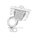
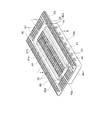
図3は本発明にかかる自動車用エアーバッグ装置を助手席用に適用した場合の要部縦断面図、図4は図3における補強枠体の全体斜視図、図5の(a),(b)は図4のB―B線,C―C線に沿った断面図、図6は図3の動作説明図である。
【0022】
図3において、40はポリプロピレン樹脂(PP)などの熱可塑性樹脂を主原料として一体成形された樹脂製のインストルメントパネルカバー(以下内装パネルという)であり、この内装パネル40は、図示省略の車体に固定された樹脂製のインストルメントパネルコアー(図示省略)の表面を覆うように構成され、タッピングネジ等の適宜の手段により、インストルメントパネルコアーに固定されている。
【0023】
前記内装パネル40の左側部分の助手席(右ハンドル車対応)と対向する内側箇所には、図3に示すように、自動車用エアーバッグ装置41が収容される収容部42が形成されている。なお、左ハンドル車対応の場合は前記構成と反対の右側部分に設けられる。
【0024】
前記自動車用エアーバッグ装置41は、インフレータからのガスにより膨張展開されるエアーバッグ43と、このエアーバッグ43を折り畳んだ状態で収容する、上方に開口44aを有するエアーバッグケース44と、前記内装パネル40と同系の熱可塑性樹脂材料を使用して一体成形された補強枠体45を備える。この補強枠体45は、枠本体46と、該枠本体46の上部に一体に形成された一対の破断開放部用の破断補強部47a,47b及び破断開放部の開口周縁用の縁補強部48とから構成される。
【0025】
前記枠本体46の下部は、図3〜図5に示すように、前側壁46a及び後側壁46bと、左側壁46c及び右側壁46dとによって矩形筒状に形成されると共に、前記枠本体46の矩形状の側壁上部には、枠本体46の上端から外方に向けて斜め上方へ延在する傾斜部46eを介して、四周面がほぼ水平となる前記縁補強部48が外方向へ延出して形成されている。また前側壁46a及び後側壁の上端部には、これら前側壁46a及び後側壁から内方へ波状に屈曲されて延在する伸び代を有するヒンジ部49を介して一対の破断補強部47a,47bが一体に連続して形成されている。この破断補強部47a,47bは、後述する破断開放部51を裏面から補強するためのものであり、縁補強部48は、後述する破断開放部51の周辺と対向する内装パネル40の領域を補強するためのものである。
【0026】
そして、前記補強枠体45を構成する枠本体46と縁補強部48及び破断補強部47a,47bはオレフィン系エラストマーなどよりなる低弾性の熱可塑性樹脂材によって射出成形により一体形成されたものである。
また、前記内装パネル40の裏面と対応する前記縁補強部48及び破断補強部47a,47bの溶着面には、所定間隔をもって突出する断裂筋条の突起部50がそれぞれ形成されており、これらの突起部50を介して前記内装パネル40裏面に縁補強部48及び破断補強部47a,47bが振動溶着によって固着されるようになっている。
【0027】
また、前記収容部42と相対向する内装パネル40には、エアーバッグ43の膨張展開時にエアーバッグの押圧力により破断されて開口する破断開放部51が形成されている。
この破断開放部51は、内装パネル40の裏面の左右長手方向に沿って設けたヒンジ溝40a及び前後の短尺方向に沿って設けた側部破断用溝40cをエアーバッグケース44の開口44aとほぼ同一の長方形状にレーザ加工等により形成することにより構成されるものであり、破断開放部51の短尺方向、すなわち側部破断用溝40cの中間には、破断開放部51の長尺方向の全長に亘り伸びる中央破断用溝40bがレーザ加工等により形成されている。このような破断開放部51は、エアーバッグ43の膨張展開時に破断開放部51が側部破断用溝40cと中央破断用溝40bの箇所から破断されることにより、図6に示すようにヒンジ溝40aにより構成されるヒンジ52,52を介して観音開き状態に展開される前,後の破断開放部51a,51bに分離されるようになっている。
【0028】
また、前記枠本体46の長手方向の前,後側壁46a,46bには複数の角穴状の係止部53が形成されており、この係止部53に前記エアーバッグケース44の前後側壁に取り付けたフック部54が係止されるようになっている。
【0029】
前記補強枠体45に一体成形された破断補強部47a,47bは、波状に屈曲された伸び代を有するヒンジ部49を介して図3に示すように、補強枠体45の内側開口を閉鎖した状態から、図6に示すようにエアーバッグ43が膨張展開できる状態に展開できるように破断開放部51a,51bに固着されている。
【0030】
本発明の実施形態においては、前記補強枠体45と破断補強部47a,47bとを一体形成により構成したので、エアーバッグ膨張展開時において、破断開放部51a,51bの変形における破断補強部47a,47bの初期の展開圧力を波状に屈曲された伸び代を有するヒンジ部49によって破断開放部51a,51bの反転における破断補強部47a,47bの伸びを充分に吸収することが可能となり、このため、破断開放部51a,51bのスムーズな展開を図ることができる。
【0031】
また、前記補強枠体45の下方には、エアーバッグ43を収納したエアーバッグケース44が配設され、ケース上端開口44aの側壁にはフック部54が設けられており、このフック部54が前記補強枠体45の係止部53に貫通係止されるようになっている。このエアーバッグケース44の下端にはエアーバッグ43にガスを供給するインフレータ(図示せず)が配設されている。
また、このエアーバッグケース44は支持部材55を介してクロスメンバー56など車体側の固定部材にボルトナット56aにより固定されるようになっている。
【0032】
以上のように構成された本発明の実施の形態による助手席用のエアーバッグ装置においては、自動車などの車両が衝突した際に、その衝突時の衝撃力を図示省略した周知のセンサで検出し、このセンサで検出した衝撃力が予め定めた値以上になった否かを図示省略した周知のCPU等からなる制御装置で判定し、設定値以上と判定された時に制御装置から出力される信号により、図示省略した周知のインフレータを動作させて所定のガスを発生させ、このガスをエアーバッグ43に供給することにより、エアーバッグ43を急速に膨張展開させる(図6参照)。
【0033】
エアーバッグ43が膨張展開する場合、エアーバッグ43の膨張展開初期時に発生する圧力が破断補強部47a,47bの水平面と補強枠体45の内側にかかると、枠本体46と縁補強部48とは、枠本体46の上端から外方に向けて斜め上方へ延在する傾斜部46eを介して連結されているため、補強枠体45に対する膨張の影響が少なく、更に縁補強部48を内下方へ引っ張るようにするため内装パネル40の開口周縁の拡がりを少なくして割れを防止すると共に、この破断補強部47a,47bの水平面に溶着された破断開放部51a,51bは中央破断用溝40bの脆弱部分から側部の破断用溝40cの脆弱部分に沿い順次破断されると共に、この前,後の破断開放部51a,51bを含む破断補強部47a,47bはヒンジ部49となる波状の折曲部を伸び代として図6に示すように展開され、破断開放部51と破断補強部47a,47bとの溶着部分に掛かる無理な圧力や力を吸収することができる。そして、展開最終段階では前記枠本体46の角穴53のギャップによっても前記圧力を吸収できることで、内装パネル40の開口周縁に発生する損傷が防止でき、破断補強部47a,47bを含む破断開放部51が図6示すようにスムーズに観音開き状態に外側へ展開される。
【0034】
以上のように、前記実施形態においては、補強枠体45を、枠本体46と一体成形した縁補強部48と枠本体46の前側壁46a及び後側壁46bに対応して前後方向に2分された破断補強部47a,47bとから構成し、そして、枠本体46の前,後側壁46a,46bに対応する一対の破断補強部47a,47bを波状に屈曲された伸び代を有するヒンジ部49を介して前,後側壁46a,46bの上部に連結し、前記破断補強部47a,47bを破断開放部51a,51bの裏面に振動溶着した構成としたので、破断補強部47a,47bの反転に伴うヒンジ部49の伸び代を確保できるため、前,後の破断開放部51a,51bと破断補強部47a,47bとの溶着部に与える衝撃力を吸収できる。
【0035】
さらに、この実施の形態によれば、破断開放部51の前後,左右の四周囲の開口周辺領域は補強枠体45の縁補強部48に溶着されているため、破断開放部51の開放動作に追従することが抑制され破断用溝46cで速やかに破断されることになり、エアーバッグ43の膨張展開時に破断された破断開放部51a,51bの破断面にシャープなエッジが生じたり、破断部にささくれ現象が生じるのを予防し、奇麗な破断面を提供できる。
【0036】
さらに、破断開放部51の開口周辺に臨む内装パネル40の領域は補強枠体45の縁補強部48により補強されているため、破断開放部51を含む内装パネル40の上方からの押圧力に対して耐圧性が増し、エアーバッグ装置の不使用時における内装パネル40の割れ、歪み等の変形を防止できる。
【0037】
また、この実施の形態によれば、内装パネル40と前記補強枠体45を同系の熱可塑性樹脂材料で構成すると共に、内装パネル40に対応する前記補強枠体45の縁補強部48と破断補強部47a,47bの溶着面には断裂筋条の突起部50を形成し、この突起部50を介して内装パネル40の裏面に振動溶着するようにしたので、溶着部に熱による変形を生じさせることなく溶着作業が容易である。
【0038】
また、エアーバッグケース44はフック部54と枠本体46に設けた係止部53とにより補強枠体45に対して分離可能に結合できる構成になっているため、廃車時などにエアーバッグケース44を補強枠体45から容易に取り外すことができ、産業廃棄物となるインフレータなどの関連部品を容易に分離除去でき、環境に悪影響を与えることが防止できる。
【0039】
図7の(a),(b)は、本発明にかかる自動車用エアーバッグ装置を助手席用に適用した場合の実施形態を示す補強枠体の変形例を示す要部の縦断面図である。
この変形例によれば、前記補強枠体145の成形時において、枠本体145の前,後側壁46a,46bの上部に、波状に屈曲された伸び代を有するヒンジ部149を介して一体に連結された一対の前記破断補強部147a,147bの互いの先端部を薄肉部147cで結合し、且つ前記破断補強部147a,147bの前後方向の幅寸法を図3に示す場合より大きくする。これにより、破断補強部147a,147bが内装パネル40の裏面に溶着される以前は、破断補強部147a,147bが前記薄肉部147cを中心にして前記ヒンジ部149の上部高さより下方又は上方へ屈曲されるように構成することで、前記破断補強部147a,147bの内装パネルの裏面に対する対応部分を長くして振動溶着部分を増大しようとするものである。
そして、前記縁補強部148及び破断補強部147a,147bを内装パネル40の裏面に振動溶着によって固着する場合には、先ず前記縁補強部148を破断開放部の開口周縁に位置決めし、次に、波状に屈曲された伸び代を有するヒンジ部149が図7(a)に示すように傾斜部146e側へ圧縮変形された状態で前記破断補強部147a,147bを前記破断開放部151の裏面に当接させて振動溶着する。
【0040】
したがって、前述の実施形態に比べ、破断補強部147a,147bの破断開放部151a,151bの裏面側に対応する振動溶着面の溶着範囲を広くでき、溶着が確実となる利点があると共に、伸び代を有するヒンジ部149が破断開放部151a,151bに近接して配設できることで、破断補強部の反転に伴うヒンジ部の伸び代を確保できるため、前,後の破断開放部と破断補強部との溶着部に与える衝撃力を吸収できる。
【0041】
また、前記実施の形態では、破断開放部151a,151bがその前後方向の中央部で分離して観音開き、すなわち両開きに開口する構成について説明したが、これに限られることなく、内装パネル内面に溶着される破断補強部の構成が若干異なるが、破断開放部が片開き構成のものについても適用できることは勿論である。
【0042】
更にまた、図8〜図10は本発明の他の実施形態を示すもので、エアーバッグ展開用の破断開放部の開口形状が四方開き方式のものに適用した状態を示す自動車用エアーバッグ装置に関するものである。
【0043】
この実施形態における補強枠体245は、前述の実施形態とほぼ同様であるが、一点鎖線で示した内装パネル240の破断開放部251a,251b,251c,251dの裏面側に振動溶着される破断補強部を4つに分割し、4つの破断補強部247a,247b,247c,247dから構成されている点が上記実施の形態と異なる。
【0044】
すなわち,図8の構成では、前記内装パネル240の裏面にエアーバッグ展開用の開口形状を決める破断用溝を形成することにより構成される破断開放部251a,251b,251c,251dは、全体が平面長方形状を呈する破断開放部を左右一対の三角形状と、該三角形状のそれぞれの頂点を結ぶ線を短片とする一対の台形状の接合面が切断されるようにした四方開き方式の破断開放部に構成し、前記補強枠体245の矩形状の上部周囲には、枠本体146の上端から外方に向けて斜め上方へ延在する傾斜部を介して水平に延出する縁補強部248を、また前記前,後側壁246a,246b及び左,右側壁246c,246dの上端部には、波状に屈曲された伸び代を有するヒンジ部249を介してそれぞれ補強枠体145の内方に前記三角形状及び台形形状に対応させて形成した一対の三角状破断補強部247c,247d及び一対の台形状破断補強部247a,247bを形成したものである。
【0045】
各破断補強部247a〜247dの溶着面及び縁補強部248の溶着面にはそれぞれ所定間隔をもって断裂筋条の突起部250を形成し、これらの突起部250を介して前記内装パネルの裏面に破断補強部247a〜247d及び縁補強部248を振動溶着によって固着する。なお、前記突起部250が、その長手方向の複数箇所で断裂した構成とすることにより振動溶着時における熱変形を少なくできる効果があるが断裂筋条に限定することなく連続する筋条であっても良いことは勿論である。
【0046】
図9の変形例によれば、図8の構成とほぼ同様であるが、左右一対の三角形状破断補強部247c,247dの先端部の形状が湾曲を呈している点で図8と相違している。先端部の形状を湾曲とすることで、エアーバッグの膨張展開時に破断開放部及び破断補強部の開放先端部に鋭利な破断面が形成されるのを防止できる。なお、図8の構成と同一部分には同一符号を付してその説明を省略する。
【0047】
図10は更に異なる変形例であって、図9の構成とほぼ同様であるが、左右一対の破断補強部247c,247dの破断部の先端部形状が弦形状を呈している点で図9と相違している。なお、図8の構成と同一部分には同一符号を付してその説明を省略する。
【0048】
なお、前記実施形態におけるヒンジ溝40a及び破断用溝40b,40cの形成は、内装パネル40の裏面側よりレーザ加工によって脆弱部を形成するようにしたが、これに限定されることなく、フライス溝加工又は型加工によっても形成出来ることは勿論であり、フライス溝加工による場合は、内装パネルの裏面側より切削して、内装パネルの表面側の肉厚を0.5mm〜0.8mmの範-囲で残し量を設けるようにすると良い。その他、表面パネルの成形時に一体成形する等の方法がある。
【0049】
【発明の効果】
上記のように構成された自動車用エアーバッグ装置によれば、補強枠体を、枠本体と、この枠本体と一体成形された縁補強部及び波状に屈曲された伸び代を有するヒンジ部を介して枠本体と一体成形された破断補強部とから構成したので、組み付けが容易で、作業性が向上すると共に、内装パネルの上面から押圧力が加えられても、補強枠体の縁補強部が内装パネルの裏面から支持しているので、破断開放部のへこみや開口周縁の変形を防止することができ、しかも、破断開放部の開口縁部及び破断開放部への縁補強部及び破断補強部の振動溶着作業を容易に行うことができる。
また、本発明によれば、枠本体と一体成形され、かつ片開き、両開きまたは四方開き可能に構成された破断補強部を波状に屈曲された伸び代を有するヒンジ部を介して枠本体の側壁の上端に一体的に連結し、この破断補強部を破断開放部の裏面に振動溶着する構成としたので、破断補強部の反転に伴うヒンジ部の伸び代を確保できるため、片開き、両開きまたは四方開き可能な破断開放部と破断補強部との溶着部に与える衝撃力を吸収できる。
更にまた、本発明によれば、前記補強枠体がオレフィン系エラストマーなどよりなる低弾性の熱可塑性樹脂材からなる前記内装パネルと同系の材質であるため、これらの接合を振動溶着によって行うことが可能となり、溶着作業が容易であると共に、リサイクル時において、従来のように金属製の枠体及び補強板材と樹脂製の内装パネルとを一々分離する作業を省略できる。
更にまた、本発明によれば、エアーバッグケースは補強枠体に対してフック部と補強枠体の係止部により分離可能に結合できる構成になっているため、廃車時などにエアーバッグを枠本体から容易に取り外すことができ、インフレータなどの関連部品を容易に分離除去でき、環境に悪影響を与えることが防止出来る効果を有する。
【0050】
また、本発明によれば、内装パネルと補強枠体を同系の熱可塑性樹脂材料で構成すると共に、内装パネルに対応する補強枠体の縁補強部と破断補強部の溶着面には断裂筋条の突起部を形成し、この突起部を介して内装パネルの裏面に振動溶着するようにしたので、溶着部に熱による変形を生じさせることなく溶着作業が容易である。
【0051】
また、本発明によれば、枠本体の前,後側壁の上端部にヒンジ部を介して一体に連結された前,後の破断補強部の互いの先端部を薄肉部で結合し、且つこれら前,後の破断補強部が破断開放部の裏面に溶着される以前は、これら前,後の破断補強部が前記薄肉部を中心にして前記ヒンジ部の上部高さより下方又は上方へ屈曲されるように前,後の破断補強部の前後方向の幅寸法を大きくし、そして、前,後の破断補強部及び縁補強部を内装パネルの裏面に振動溶着によって固着する時は、波状に屈曲された伸び代を有するヒンジ部が傾斜部146e側へ圧縮変形された状態で前記破断補強部が前記破断開放部の裏面に当接されるように構成したので、破断補強部の破断開放部の裏面に対する振動溶着面の溶着範囲を広くでき、溶着が確実となる利点があると共に、伸び代を有するヒンジ部が破断開放部に近接して配設できることで、破断補強部の反転に伴うヒンジ部の伸び代を確保できるため、破断開放部と破断補強部との溶着部に与える衝撃力を吸収できる。
【図面の簡単な説明】
【図1】 従来の助手席用エアーバッグ装置の単板状の内装パネルにエアーバッグ膨張展開用の破断開放部を形成した状態を示す部分拡大説明図。
【図2】 図2は図1のA−A線に沿う概略断面図。
【図3】 本発明にかかる自動車用エアーバッグ装置を助手席用に適用した場合の実施形態を示す要部の縦断面図。
【図4】 図3における補強枠体の全体斜視図。
【図5】 (a),(b)はそれぞれ本発明にかかる図4の補強枠体におけるB-B線及びC−C線の断面斜視図。
【図6】 図3の作動状態を示す説明用断面図。
【図7】 (a),(b)は、本発明にかかる自動車用エアーバッグ装置を助手席用に適用した場合の実施形態を示す補強枠体の変形例を示す要部の縦断面図である。
【図8】 本発明の他の実施形態を示すもので、エアーバッグ展開用の破断開放部の開口形状が四方開き方式のものに適用した状態を示す補強枠体の全体斜視図である。
【図9】 本発明の他の実施形態を示すもので、エアーバッグ展開用の破断開放部の開口形状が四方開き方式のものに適用した状態を示す補強枠体の全体斜視図である。
【図10】 本発明の他の実施形態を示すもので、エアーバッグ展開用の破断開放部の開口形状が四方開き方式のものに適用した状態を示す補強枠体の全体斜視図である。
【符号の説明】
40 内装パネル
40a ヒンジ溝
40b 中央破断用溝
40c 側部破断用溝
41 自動車用エアーバッグ装置
42 収容部
43 エアーバッグ
44 エアーバッグケース
45 補強枠体
46 枠本体
47a,47b 破断補強部
48 縁補強部
49 ヒンジ部
50 突起部
51 破断開放部
53 角穴状の係止部
54 フック部[0001]
BACKGROUND OF THE INVENTION
The present invention relates to an automotive airbag apparatus for protecting passengers in a passenger seat, driver's seat, or the like from a frontal collision or a side collision at the time of a vehicle collision such as an automobile, and ensuring the safety of the passenger. In particular, the present invention relates to an improvement in the mounting structure of the reinforcing member.
[0002]
[Prior art]
Airbag devices for passenger seats, driver's seats, and left and right side pillars applied to vehicles such as automobiles are basically an air bag and an air bag case that accommodates the air bag in a folded state. An inflator for inflating and deploying the air bag is provided, and the air bag device is arranged inside the vehicle interior panel.
The interior panel of an automobile is generally composed of an instrument panel made of a plastic resin such as a polypropylene resin that covers the surface of a panel core integrally formed of a plastic resin material such as a polypropylene resin.
[0003]
2. Description of the Related Art As a conventional automobile airbag device, a seamless type airbag device for a passenger seat is provided in which a breaking groove of a breaking open portion as shown in FIGS. 1 and 2 is difficult to see.
That is, in FIG. 1 and FIG. 2, a laser generated in a pulse form from a laser generating means (not shown) is folded on the
Further, the break
[0004]
When the break
In order not to obstruct the opening of the front and rear break
[0005]
In the automotive airbag device configured as described above, when a vehicle collides, the impact force at the time of the collision is detected by a sensor, and the impact force detected by this sensor becomes a predetermined value or more. A control device comprising a CPU or the like, and when it is determined that the value is equal to or greater than a set value, the inflator is operated by a signal output from the control device to generate a predetermined gas, and this gas is supplied to the airbag. As a result, the airbag is rapidly inflated and deployed.
[0006]
That is, when the air bag is inflated and deployed, the breaking
At the same time, the
[0007]
[Problems to be solved by the invention]
By the way, in the above-described automobile airbag device, the reinforcing
In addition, when the air bag device is activated, in the initial stage of inflation of the air bag, the inner side of the reinforcing
[0008]
Further, reinforcing
[0009]
The present invention has been made to solve the above-described conventional problems, and an object of the present invention is to provide a break open portion of an interior panel that covers an inner front portion, a side pillar portion, a handle central portion, and the like of a vehicle, and It is possible to improve the pressure resistance against the pressing load from the outside to the vicinity of the outer peripheral edge of the opening, the rupture reinforcing portion welded to the back surface of the break open portion of the interior panel, and the back surface around the outside of the break open portion By forming the reinforcement frame body with the edge reinforcement part that reinforces the interior panel material with a thermoplastic material similar to the interior panel material, the interior panel and the reinforcement frame body can be joined by vibration welding, making assembly easy Another object of the present invention is to provide an automotive airbag device that does not require separation work during recycling.
[0010]
In addition, the present invention prevents cracking at the edge of the fracture opening, and forms the frame main body and the integrally formed fracture reinforcement portion and edge reinforcement portion with a low-elasticity thermoplastic resin material such as an olefin elastomer, Hinge extension allowance can be secured reliably, absorbing the development pressure applied to the fracture opening and its surrounding area, smooth opening of the fracture opening, and easy installation work of vibration welding with the back of the interior panel It is an object of the present invention to provide an automotive airbag device that can be made to have a clean fracture surface by preventing sharp edges from occurring on the fracture surface and preventing occurrence of a crushing phenomenon at the fracture portion.
[0011]
[Means for Solving the Problems]
In order to achieve the above object, an invention according to claim 1 of the present invention is an air bag device for an automobile, which is disposed on the back side of an interior panel provided in the interior of the automobile, and is provided with gas from an inflator. An air bag case for storing an inflated and deployed air bag in a folded state, and a breakage groove formed on the back surface of the interior panel facing the air bag case opening to determine the air bag opening shape. The fracture opening part which exhibits a plane rectangular shape configured to be openable by one side,
A frame body made of a synthetic resin, and a reinforcing frame body made of a synthetic resin having a fracture reinforcing portion and an edge reinforcing portion integrally formed on the upper end portion of the frame body, and the frame body is attached to the frame body. With a locking part to which the air bag case is connected, The frame main body has a front and rear side walls and a left and right side wall, and is formed in a rectangular cylindrical shape so as to surround the fracture opening portion. In order to reinforce the breaking opening, it is fixed to the back surface of the breaking opening, The edge reinforcement portions are provided on the upper end portions of the front and rear side walls and the left and right side walls through inclined portions provided to extend obliquely upward from the upper end portions outward. It extends horizontally from the upper end to the outside, The edge reinforcement is Affixed to the back surface of the region to reinforce the region of the interior panel located around the break opening, Front and rear wall Between any one of the upper end portions and the rupture reinforcing portion facing this, It extends over the entire length of the upper end of one of the front and rear side walls, and extends from the upper end toward the inside of the frame body and bends in a wave shape. Have a stretch allowance And having a thickness equivalent to the thickness of the fracture reinforcing portion It is connected through a hinge part made of synthetic resin.
[0012]
The invention of claim 2 is an air bag apparatus for an automobile, which is disposed on the back side of an interior panel provided in the interior of the automobile and accommodates an airbag inflated and deployed by gas from an inflator in a folded state. And a flat rectangular shape configured to be double-opened by a breaking groove that is formed on the back surface of the interior panel opposite to the opening of the airbag case and determines the opening shape for airbag deployment. The break opening portion, a synthetic resin frame body, and a synthetic resin reinforcing frame body having a break reinforcement portion and an edge reinforcement portion integrally formed on the upper end portion of the frame body, the frame body, The frame body includes a locking portion to which the airbag case is connected, The frame main body has a front and rear side walls and a left and right side wall, and is formed in a rectangular cylindrical shape so as to surround the fracture opening portion. In order to reinforce the breaking opening, it is fixed to the back surface of the breaking opening, The edge reinforcement portions are provided on the upper end portions of the front and rear side walls and the left and right side walls through inclined portions provided to extend obliquely upward from the upper end portions outward. It extends horizontally from the upper end to the outside, The edge reinforcement is In order to reinforce the area of the interior panel located around the break open part, it is fixed to the back surface of the area, and the break open part can be opened both front and front of the frame main body corresponding to the front, After being divided into two parts, between the front and rear fracture reinforcing parts divided into the two parts and the upper end parts of the front and rear side walls facing the same, It extends over the entire length of the upper end portions of the front and rear side walls, and extends from the upper end portions of the front and rear side walls toward the inside of the frame body and bends in a wave shape. Have a stretch allowance And having a thickness equivalent to the thickness of the fracture reinforcing portion It is characterized by being connected through respective hinge parts made of synthetic resin.
[0013]
According to a third aspect of the present invention, there is provided an air bag apparatus for an automobile, which is disposed on the back side of an interior panel provided in the interior of the automobile and accommodates an airbag that is inflated and deployed by gas from an inflator in a folded state. A flat rectangular shape configured to be openable in four directions by an air bag case that is formed on the back surface of the interior panel opposite to the opening of the air bag case and determining a shape of the air bag deployment opening. It consists of a reinforcing frame having a fracture opening portion to be exhibited, a frame main body made of a synthetic resin material, and a fracture reinforcing portion and an edge reinforcing portion made of a synthetic resin material integrally formed with the frame main body, The frame body has a locking portion for connecting the airbag case, The frame main body has a front and rear side walls and a left and right side wall, and is formed in a rectangular cylindrical shape so as to surround the fracture opening portion. In order to reinforce the breaking opening, it is fixed to the back surface of the breaking opening, The edge reinforcement portions are provided on the upper end portions of the front and rear side walls and the left and right side walls through inclined portions provided to extend obliquely upward from the upper end portions outward. It extends horizontally from the upper end to the outside, The edge reinforcement is In order to reinforce the area of the interior panel located around the break open part, it is fixed to the back surface of the area, and the break open part has a flat rectangular shape and can be opened in four directions before and after the frame body. The front, rear, left and right parts are divided into four parts corresponding to the side wall and the left and right side walls. Between the walls The front and rear side walls and the left and right side walls extend over the entire length, and extend from the front and rear side walls and the left and right side wall upper ends toward the inside of the frame main body to be corrugated. Bend Have a stretch allowance And having a thickness equivalent to the thickness of the fracture reinforcing portion It is characterized by being connected through respective hinge parts made of synthetic resin.
[0014]
According to a fourth aspect of the present invention, in the automotive airbag device according to any one of the first to third aspects, the frame main body, the reinforcing frame body including the fracture reinforcing portion and the edge reinforcing portion are olefin-based. Integrated with low-elasticity thermoplastic resin material such as elastomer Shape It is characterized by that.
[0015]
According to a fifth aspect of the present invention, in the automotive airbag device according to any one of the first to third aspects, the fracture reinforcing portion and the edge reinforcing portion are fixed to the back surface of the interior panel by vibration welding. It is characterized by being.
[0016]
According to a sixth aspect of the present invention, in the automobile airbag device according to the second or third aspect, the edge reinforcing portion is provided via an inclined portion extending obliquely upward from the upper end portion of the frame body outward. Connected to the upper end of the frame body, the front and rear of the frame main body connected to the upper end of the rear side wall via the hinge part, the front and rear of the rupture reinforcement part is connected to each other with a thin part, And the length in the front-rear direction of the front and rear break reinforcement portions corresponding to the back surface of the break open portion, the front and rear break reinforcement portions being lower than the upper height of the hinge portion around the thin portion, or It is formed to a length that can be bent upward and protrude, and the front and rear fracture reinforcing portions and the edge reinforcing portion are brought into contact with the back surface of the interior panel and vibration welded. On the occasion Press the front and rear rupture reinforcements against the back of the rupture opening. By The hinge portion having an extension allowance is configured to be compressed and deformed toward the inclined portion side.
[0017]
A seventh aspect of the present invention is the air bag device for an automobile according to any one of the first to third aspects, wherein the frame main body and the air bag case are an engaging portion and an air bag case provided on the frame main body. And a hook portion provided in the detachable combination.
[0018]
According to an eighth aspect of the present invention, in the automobile airbag device according to any one of the first to third aspects, the welding surface of each of the fracture reinforcing portion and the edge reinforcing portion on the back surface of the interior panel is predetermined. Protrusions of streaks are formed at intervals, and the fracture reinforcing part and the edge reinforcing part are fixed to the back surface of the interior panel by vibration welding via these protrusions.
[0019]
According to a ninth aspect of the present invention, in the automobile airbag device according to any one of the first to third aspects, a hook portion attached to the airbag case is engaged with a front side wall and a rear side wall of the frame body. Each of the square hole-shaped engaging portions is formed.
[0020]
According to a tenth aspect of the present invention, in the automobile airbag device according to any one of the first to third aspects, the welding surfaces of the fracture reinforcing portion and the edge reinforcing portion on the back surface of the interior panel are predetermined. Protruding portions for vibration welding having a tearing streak shape are formed at intervals.
[0021]
DETAILED DESCRIPTION OF THE INVENTION
Next, an embodiment of an automobile airbag device according to the present invention will be described with reference to the drawings.
FIG. 3 is a longitudinal sectional view of a main part when the automotive airbag device according to the present invention is applied to a passenger seat, FIG. 4 is an overall perspective view of the reinforcing frame in FIG. 3, and FIGS. ) Is a cross-sectional view taken along lines BB and CC in FIG. 4, and FIG. 6 is an operation explanatory view of FIG.
[0022]
In FIG. 3,
[0023]
As shown in FIG. 3, a
[0024]
The
[0025]
As shown in FIGS. 3 to 5, the lower portion of the
[0026]
The frame
Further, the
[0027]
In addition, the
The
[0028]
A plurality of square hole-shaped
[0029]
As shown in FIG. 3, the
[0030]
In the embodiment of the present invention, the reinforcing
[0031]
Further, an
The
[0032]
The airbag apparatus for the passenger seat according to the embodiment of the present invention configured as described above. Oh In this case, when a vehicle such as an automobile collides, the impact force at the time of the collision is detected by a well-known sensor (not shown), and whether or not the impact force detected by this sensor exceeds a predetermined value is illustrated. It is determined by a control device including a well-known CPU that is omitted, and a predetermined gas is generated by operating a well-known inflator (not shown) by a signal output from the control device when it is determined to be equal to or greater than a set value. Is supplied to the
[0033]
When the
[0034]
As described above, in the above-described embodiment, the reinforcing
[0035]
Furthermore, according to this embodiment, the front and rear, and the four peripheral areas around the opening and closing of the
[0036]
Furthermore, the region of the
[0037]
Moreover, according to this embodiment, the
[0038]
Further, since the
[0039]
(A), (b) of Drawing 7 is a longitudinal section of the important section showing the modification of the reinforcement frame which shows the embodiment at the time of applying the air bag device for vehicles concerning the present invention for a passenger seat. .
In this variant According to At the time of molding of the reinforcing
The
[0040]
Therefore, as compared with the above-described embodiment, there is an advantage that the welding range of the vibration welding surface corresponding to the back side of the
[0041]
In the above-described embodiment, the configuration in which the
[0042]
8 to 10 show another embodiment of the present invention, which relates to an automotive airbag apparatus showing a state in which the opening shape of a break opening portion for deploying an airbag is applied to a four-way opening type. Is.
[0043]
The
[0044]
That is, in the configuration of FIG. 8, the
[0045]
Protruding
[0046]
9 is substantially the same as the configuration of FIG. 8, but is different from FIG. 8 in that the shape of the tip of the pair of left and right triangular
[0047]
FIG. 10 shows a further different modification, which is substantially the same as the configuration of FIG. 9, but is different from that of FIG. 9 in that the shape of the tip of the breakage portion of the pair of left and right
[0048]
In the embodiment, the
[0049]
【The invention's effect】
According to the automotive airbag device configured as described above, the reinforcing frame body includes the frame main body and the edge reinforcing portion integrally formed with the frame main body. as well as Has stretch allowance bent in a wave shape Ruhi Since it is composed of a rupture reinforcement part integrally formed with the frame body via the flange part, assembly is easy, workability is improved, and even if a pressing force is applied from the upper surface of the interior panel, the reinforcement frame body Since the edge reinforcing part is supported from the back surface of the interior panel, it is possible to prevent dents in the opening part of the break and deformation of the opening periphery, and the edge reinforcing part to the opening edge part of the opening part and the opening part of the breaking part. In addition, the vibration welding operation of the fracture reinforcing portion can be easily performed.
Further, according to the present invention, the side wall of the frame main body is formed through the hinge portion having an extension allowance that is integrally formed with the frame main body and that is configured to be capable of being opened in one side, double-opening, or four-way open and bent in a wave shape. Since the rupture reinforcement part is vibration welded to the back surface of the rupture opening part, the extension allowance of the hinge part accompanying the inversion of the rupture reinforcement part can be secured. The impact force applied to the welded portion between the break opening portion and the break reinforcement portion that can be opened in four directions can be absorbed.
Furthermore, according to the present invention, since the reinforcing frame is made of the same material as the interior panel made of a low-elasticity thermoplastic resin material made of an olefin-based elastomer, the joining can be performed by vibration welding. This makes it possible to easily perform the welding operation, and at the time of recycling, it is possible to omit the work of separating the metal frame body and the reinforcing plate material from the resin interior panel one by one.
Furthermore, according to the present invention, the airbag case is configured to be separably coupled to the reinforcing frame body by the hook portion and the engaging portion of the reinforcing frame body. It can be easily removed from the main body, and related parts such as an inflator can be easily separated and removed, thereby preventing adverse effects on the environment.
[0050]
Further, according to the present invention, the interior panel and the reinforcing frame are made of the same thermoplastic resin material, and the tear stripes are formed on the welded surfaces of the edge reinforcing portion and the fracture reinforcing portion of the reinforcing frame corresponding to the interior panel. Since the projection portion is formed and vibration welded to the back surface of the interior panel through the projection portion, the welding operation is easy without causing deformation of the weld portion due to heat.
[0051]
Further, according to the present invention, the front and rear rupture reinforcing portions connected integrally to the front and rear upper end portions of the frame main body via the hinge portion are coupled to each other with a thin portion, and Before these front and rear fracture reinforcement parts are welded to the back surface of the fracture opening part, these front and rear fracture reinforcement parts are bent downward or upward from the upper height of the hinge part around the thin part. When the front and rear break reinforcement parts are enlarged in the front-rear direction and the front and rear break reinforcement parts and the edge reinforcement parts are fixed to the back surface of the interior panel by vibration welding, they are bent in a wave shape. The breakage reinforcing portion is brought into contact with the back surface of the breakage opening portion in a state where the hinge portion having the extended allowance is compressed and deformed toward the inclined portion 146e. Since it is constructed, the welding range of the vibration welding surface with respect to the back surface of the fracture opening part of the fracture reinforcing part can be widened, and there is an advantage that the welding is ensured, and the hinge part having an extension allowance is arranged close to the fracture opening part. By being able to do so, it is possible to secure the allowance for extension of the hinge portion accompanying the reversal of the breakage reinforcing portion, so that it is possible to absorb the impact force applied to the welded portion between the break opening portion and the breakage reinforcing portion.
[Brief description of the drawings]
FIG. 1 is a partially enlarged explanatory view showing a state in which a break opening portion for inflating and deploying an airbag is formed on a single-panel interior panel of a conventional passenger airbag device.
FIG. 2 is a schematic sectional view taken along line AA in FIG.
FIG. 3 is a longitudinal sectional view of an essential part showing an embodiment in which an automobile airbag device according to the present invention is applied to a passenger seat.
4 is an overall perspective view of a reinforcing frame body in FIG. 3. FIG.
5A and 5B are cross-sectional perspective views taken along lines BB and CC, respectively, in the reinforcing frame of FIG. 4 according to the present invention.
6 is an explanatory cross-sectional view showing the operating state of FIG. 3; FIG.
7 (a) and 7 (b) are longitudinal sectional views of the main part showing a modification of the reinforcing frame body showing the embodiment when the automotive airbag device according to the present invention is applied to a passenger seat. is there.
FIG. 8 shows another embodiment of the present invention, and is an overall perspective view of a reinforcing frame showing a state in which an opening shape of a break opening portion for deploying an airbag is applied to a four-way opening type.
FIG. 9 shows another embodiment of the present invention, and is an overall perspective view of a reinforcing frame showing a state in which an opening shape of a break opening portion for deploying an airbag is applied to a four-way opening type.
FIG. 10 shows another embodiment of the present invention, and is an overall perspective view of a reinforcing frame showing a state in which an opening shape of a break opening portion for deploying an airbag is applied to a four-way opening type.
[Explanation of symbols]
40 Interior panel
40a Hinge groove
40b Center breaking groove
40c Side break groove
41 Airbag device for automobile
42 receiving section
43 Airbag
44 Airbag Case
45 Reinforcement frame
46 Frame body
47a, 47b Breaking reinforcement
48 Edge reinforcement
49 Hinge
50 Protrusion
51 Break opening
53 Square hole-shaped locking part
54 Hook
Claims (10)
自動車の室内に設けられた内装パネルの裏面側に配設され、インフレータからのガスにより膨張展開されるエアーバッグを折り畳んだ状態で収納するエアーバッグケースと、
前記エアーバッグケースの開口と相対向する前記内装パネルの裏面に形成された、エアーバッグ展開用の開口形状を決める破断用溝によって片開き可能に構成された平面長方形状を呈する破断開放部と、
合成樹脂製の枠本体と、前記枠本体の上端部に一体成形された破断補強部及び縁補強部とを有する合成樹脂製の補強枠体とからなり、
前記枠本体は、該枠本体に前記エアーバッグケースが連結される係止部を備え、
前記枠本体は、前,後側壁と左,右側壁を有して前記破断開放部を囲むように矩形筒状に形成され、
前記破断補強部は前記破断開放部を補強するために前記破断開放部の裏面に固着され、
前記前,後側壁及び前記左,右側壁の上端部には、該上端部から外方に向けて斜め上方へ延在して設けられた傾斜部を介して前記縁補強部が前記上端部から外方向へ水平に延在して設けられ、
前記縁補強部は前記破断開放部の周囲に位置する前記内装パネルの領域を補強するために前記領域の裏面に固着され、
前記前,後側壁の何れか一方の上端部とこれに対向する前記破断補強部との間は、前記前,後側壁の何れか一方の上端部の全長に亘り延在し、かつ前記上端部から前記枠本体の内方に向け延在して波状に屈曲する伸び代を有するとともに前記破断補強部の厚さと同等の厚さを有する合成樹脂製のヒンジ部を介して連結されていることを特徴とする自動車用エアーバッグ装置。An airbag device for an automobile,
An airbag case that is disposed on the back side of an interior panel provided in the interior of an automobile and stores an airbag inflated and deployed by gas from an inflator in a folded state;
A break opening portion that is formed on the back surface of the interior panel opposite to the opening of the airbag case and has a flat rectangular shape that is configured to be openable by a break groove that determines an opening shape for airbag deployment;
It consists of a synthetic resin frame body, and a synthetic resin reinforcing frame body having a fracture reinforcing part and an edge reinforcing part integrally formed on the upper end part of the frame main body,
The frame body includes a locking portion to which the airbag case is coupled to the frame body,
The frame body has a front and rear side walls and a left and right side wall and is formed in a rectangular cylindrical shape so as to surround the fracture opening portion,
The rupture reinforcement is secured to the back of the rupture opening to reinforce the rupture opening;
The edge reinforcing portion is connected to the upper end portion of the front and rear side walls and the left and right side walls from the upper end portion through an inclined portion extending obliquely upward from the upper end portion outward. Extending horizontally outwards,
The edge reinforcing portion is fixed to the back surface of the region in order to reinforce the region of the interior panel located around the fracture opening portion,
The upper end of either the front or rear side wall extends between the upper end of either the front or rear side wall and the upper portion of the upper end of the front or rear side wall. Extending from the inside of the frame body to the inside of the frame body and having an allowance for bending in a wavy shape and being connected via a hinge portion made of synthetic resin having a thickness equivalent to the thickness of the fracture reinforcing portion A feature of an air bag device for automobiles.
自動車の室内に設けられた内装パネルの裏面側に配設され、インフレータからのガスにより膨張展開されるエアーバッグを折り畳んだ状態で収納するエアーバッグケースと、
前記エアーバッグケースの開口と相対向する前記内装パネルの裏面に形成された、エアーバッグ展開用の開口形状を決める破断用溝によって両開き可能に構成された平面長方形状を呈する破断開放部と、
合成樹脂製の枠本体と、前記枠本体の上端部に一体成形された破断補強部及び縁補強部とを有する合成樹脂製の補強枠体とからなり、
前記枠本体は、該枠本体に前記エアーバッグケースが連結される係止部を備え、
前記枠本体は、前,後側壁と左,右側壁を有して前記破断開放部を囲むように矩形筒状に形成され、
前記破断補強部は前記破断開放部を補強するために前記破断開放部の裏面に固着され、
前記前,後側壁及び前記左,右側壁の上端部には、該上端部から外方に向けて斜め上方へ延在して設けられた傾斜部を介して前記縁補強部が前記上端部から外方向へ水平に延在して設けられ、
前記縁補強部は前記破断開放部の周囲に位置する前記内装パネルの領域を補強するために前記領域の裏面に固着され、
前記破断開放部は両開きできるように前記枠本体の前,後側壁に対応して前,後に2分割され、
前記2分割された前,後の破断補強部とこれに対向する前記前,後側壁の上端部との間は、前記前,後側壁の上端部の全長に亘り延在し、かつ前記前,後側壁の上端部から前記枠本体の内方に向け延在して波状に屈曲する伸び代を有するとともに前記破断補強部の厚さと同等の厚さを有する合成樹脂製のそれぞれのヒンジ部を介して連結されていることを特徴とする自動車用エアーバッグ装置。An airbag device for an automobile,
An airbag case that is disposed on the back side of an interior panel provided in the interior of an automobile and stores an airbag inflated and deployed by gas from an inflator in a folded state;
A break opening portion that is formed on the back surface of the interior panel opposite to the opening of the airbag case and has a flat rectangular shape that can be double-opened by a breaking groove that determines the opening shape for airbag deployment;
It consists of a synthetic resin frame body, and a synthetic resin reinforcing frame body having a fracture reinforcing part and an edge reinforcing part integrally formed on the upper end part of the frame main body,
The frame body includes a locking portion to which the airbag case is coupled to the frame body,
The frame body has a front and rear side walls and a left and right side wall and is formed in a rectangular cylindrical shape so as to surround the fracture opening portion,
The rupture reinforcement is secured to the back of the rupture opening to reinforce the rupture opening;
The edge reinforcing portion is connected to the upper end portion of the front and rear side walls and the left and right side walls from the upper end portion through an inclined portion extending obliquely upward from the upper end portion outward. Extending horizontally outwards,
The edge reinforcing portion is fixed to the back surface of the region in order to reinforce the region of the interior panel located around the fracture opening portion,
The break opening part is divided into two parts, front and rear, corresponding to the front and rear side walls of the frame body so that both sides can be opened.
The front and rear fracture reinforcing portions divided into two and the upper ends of the front and rear side walls that oppose each other extend over the entire length of the upper ends of the front and rear side walls, and the front, Via the respective hinge portions made of synthetic resin having an extension allowance extending from the upper end portion of the rear side wall toward the inside of the frame main body and bending in a wave shape, and having a thickness equivalent to the thickness of the fracture reinforcing portion An air bag device for automobiles, characterized in that they are connected together.
自動車の室内に設けられた内装パネルの裏面側に配設され、インフレータからのガスにより膨張展開されるエアーバッグを折り畳んだ状態で収納するエアーバッグケースと、
前記エアーバッグケースの開口と相対向する前記内装パネルの裏面に形成された、エアーバッグ展開用の開口形状を決める破断用溝によって四方開き可能に構成された平面長方形状を呈する破断開放部と、
合成樹脂材からなる枠本体と、前記枠本体と一体成形された合成樹脂材からなる破断補強部及び縁補強部とを有する補強枠体とからなり、
前記枠本体は、該枠本体に前記エアーバッグケースを連結する係止部を備え、
前記枠本体は、前,後側壁と左,右側壁を有して前記破断開放部を囲むように矩形筒状に形成され、
前記破断補強部は前記破断開放部を補強するために前記破断開放部の裏面に固着され、
前記前,後側壁及び前記左,右側壁の上端部には、該上端部から外方に向けて斜め上方へ延在して設けられた傾斜部を介して前記縁補強部が前記上端部から外方向へ水平に延在して設けられ、
前記縁補強部は前記破断開放部の周囲に位置する前記内装パネルの領域を補強するために前記領域の裏面に固着され、
前記破断開放部は平面長方形状を呈するとともに四方開きできるように前記枠本体の前,後側壁と左,右側壁に対応して前,後と左,右の部分に4分割され、
前記4分割された各破断補強部とこれらに対向する前記枠本体の前,後側壁及び左,右側壁との間は、前記前,後側壁及び左,右側壁の上端部の全長に亘り延在し、かつ前記前,後側壁及び左,右側壁の上端部から前記枠本体の内方に向け延在して波状に屈曲する伸び代を有するとともに前記破断補強部の厚さと同等の厚さを有する合成樹脂製のそれぞれのヒンジ部を介して連結されていることを特徴とする自動車用エアーバッグ装置。An airbag device for an automobile,
An airbag case that is disposed on the back side of an interior panel provided in the interior of an automobile and stores an airbag inflated and deployed by gas from an inflator in a folded state;
A break opening portion that is formed on the back surface of the interior panel opposite to the opening of the airbag case and has a flat rectangular shape that is configured to be openable in four directions by a breaking groove that determines the opening shape for airbag deployment;
It consists of a frame body made of a synthetic resin material, and a reinforcing frame body having a fracture reinforcement portion and an edge reinforcement portion made of a synthetic resin material integrally molded with the frame body,
The frame body includes a locking portion that connects the airbag case to the frame body,
The frame body has a front and rear side walls and a left and right side wall and is formed in a rectangular cylindrical shape so as to surround the fracture opening portion,
The rupture reinforcement is secured to the back of the rupture opening to reinforce the rupture opening;
The edge reinforcing portion is connected to the upper end portion of the front and rear side walls and the left and right side walls from the upper end portion through an inclined portion extending obliquely upward from the upper end portion outward. Extending horizontally outwards,
The edge reinforcing portion is fixed to the back surface of the region in order to reinforce the region of the interior panel located around the fracture opening portion,
The break opening portion is rectangular in plane and is divided into four parts, front, rear, left and right, corresponding to the front, rear side wall and left, right side wall of the frame body so that it can be opened in four directions,
Between each of the four divided reinforcing portions and the front, rear side wall, left and right side walls of the frame main body facing each other, it extends over the entire length of the upper ends of the front, rear side wall, left and right side walls. And having an extension allowance extending from the upper ends of the front, rear and left and right side walls toward the inside of the frame body and bending in a wave shape, and having a thickness equivalent to the thickness of the fracture reinforcing portion An automobile airbag device, wherein the airbag devices are connected via respective hinge portions made of synthetic resin.
Priority Applications (6)
| Application Number | Priority Date | Filing Date | Title |
|---|---|---|---|
| JP2002228758A JP4285678B2 (en) | 2002-08-06 | 2002-08-06 | Airbag device for automobile |
| AU2003204141A AU2003204141B2 (en) | 2002-08-06 | 2003-05-12 | Airbag Apparatus for Automobile |
| DE60333615T DE60333615D1 (en) | 2002-08-06 | 2003-05-23 | Airbag device for motor vehicles |
| EP20030101505 EP1388467B1 (en) | 2002-08-06 | 2003-05-23 | Airbag apparatus for automobile |
| AT03101505T ATE476327T1 (en) | 2002-08-06 | 2003-05-23 | AIRBAG DEVICE FOR MOTOR VEHICLES |
| US10/449,135 US7007970B2 (en) | 2002-08-06 | 2003-05-28 | Airbag apparatus for automobile |
Applications Claiming Priority (1)
| Application Number | Priority Date | Filing Date | Title |
|---|---|---|---|
| JP2002228758A JP4285678B2 (en) | 2002-08-06 | 2002-08-06 | Airbag device for automobile |
Publications (2)
| Publication Number | Publication Date |
|---|---|
| JP2004066955A JP2004066955A (en) | 2004-03-04 |
| JP4285678B2 true JP4285678B2 (en) | 2009-06-24 |
Family
ID=30437738
Family Applications (1)
| Application Number | Title | Priority Date | Filing Date |
|---|---|---|---|
| JP2002228758A Expired - Lifetime JP4285678B2 (en) | 2002-08-06 | 2002-08-06 | Airbag device for automobile |
Country Status (6)
| Country | Link |
|---|---|
| US (1) | US7007970B2 (en) |
| EP (1) | EP1388467B1 (en) |
| JP (1) | JP4285678B2 (en) |
| AT (1) | ATE476327T1 (en) |
| AU (1) | AU2003204141B2 (en) |
| DE (1) | DE60333615D1 (en) |
Families Citing this family (70)
| Publication number | Priority date | Publication date | Assignee | Title |
|---|---|---|---|---|
| JP3973029B2 (en) * | 2002-03-28 | 2007-09-05 | 三光合成株式会社 | Airbag device for automobile |
| JP4011441B2 (en) * | 2002-05-10 | 2007-11-21 | ダイハツ工業株式会社 | Instrument panel structure of vehicle |
| JP2004098734A (en) * | 2002-09-05 | 2004-04-02 | Toyota Auto Body Co Ltd | Air bag door structure |
| DE60307198T2 (en) * | 2002-10-15 | 2007-07-19 | Nishikawa Kasei Co. Ltd. | Airbag cover for a vehicle |
| JP4337340B2 (en) * | 2002-12-12 | 2009-09-30 | タカタ株式会社 | Airbag device |
| JP4173381B2 (en) * | 2003-02-21 | 2008-10-29 | しげる工業株式会社 | Air grid structure |
| US7014208B2 (en) * | 2003-03-21 | 2006-03-21 | Lear Corporation | Interior vehicle trim panel |
| US7219922B2 (en) * | 2003-05-05 | 2007-05-22 | Lear Corporation | Interior vehicle trim panel |
| US7140636B2 (en) * | 2003-05-07 | 2006-11-28 | Lear Corporation | Airbag support assembly for a vehicle instrument panel |
| KR100580466B1 (en) * | 2003-11-27 | 2006-05-15 | 현대자동차주식회사 | A passenger air bag expansion structure with seamless being application of sliding hinge |
| US7160404B2 (en) * | 2003-12-10 | 2007-01-09 | Lear Corporation | Method of manufacturing an airbag assembly and vehicle trim component |
| JP4570397B2 (en) * | 2004-05-24 | 2010-10-27 | カルソニックカンセイ株式会社 | Airbag module removal structure |
| US20050269804A1 (en) * | 2004-05-27 | 2005-12-08 | Satoshi Yamada | Cover of air bag apparatus and manufacturing method thereof |
| JP2006051907A (en) | 2004-08-16 | 2006-02-23 | Moriroku Co Ltd | Airbag device for vehicle |
| DE102004053132A1 (en) * | 2004-10-29 | 2006-05-18 | Faurecia Innenraum Systeme Gmbh | Airbag flap system |
| US7234726B2 (en) | 2004-12-16 | 2007-06-26 | Visteon Global Technologies, Inc. | Airbag assembly for improving force distribution |
| JP4541138B2 (en) * | 2004-12-28 | 2010-09-08 | 日本プラスト株式会社 | Instrument panel for automobile |
| US8038168B2 (en) | 2005-05-02 | 2011-10-18 | Intertec Systems | Automotive P.S.I.R. milling burr control tape |
| JP4838539B2 (en) | 2005-05-31 | 2011-12-14 | 三光合成株式会社 | Airbag device for vehicle |
| JP4831999B2 (en) * | 2005-05-31 | 2011-12-07 | 三光合成株式会社 | VEHICLE AIRBACK DEVICE AND AIRBACK COVER |
| DE102005027271B4 (en) * | 2005-06-08 | 2011-06-01 | Takata-Petri Ag | Cover for an airbag module |
| JP4717532B2 (en) * | 2005-07-05 | 2011-07-06 | 三光合成株式会社 | Airbag device for automobile |
| JP4963470B2 (en) * | 2005-07-06 | 2012-06-27 | オートリブ ディベロップメント エービー | Airbag device for passenger seat |
| US9165920B2 (en) * | 2005-10-15 | 2015-10-20 | Globalfoundries Singapore Pte. Ltd. | Tunable protection system for integrated circuits |
| JP2007118688A (en) * | 2005-10-26 | 2007-05-17 | Takata Corp | Interior panel assembly and airbag device |
| JP4746409B2 (en) * | 2005-11-17 | 2011-08-10 | 三光合成株式会社 | Airbag device for vehicle |
| JP2007153069A (en) * | 2005-12-02 | 2007-06-21 | Takata Corp | Interior panel assembly and airbag device |
| JP2007245876A (en) * | 2006-03-15 | 2007-09-27 | Takata Corp | Air bag device |
| JP4710677B2 (en) * | 2006-03-22 | 2011-06-29 | トヨタ自動車株式会社 | Retainer mounting structure |
| US7669884B2 (en) * | 2006-05-09 | 2010-03-02 | Honda Motor Co., Ltd. | Air bag device |
| KR100767523B1 (en) * | 2006-08-24 | 2007-10-17 | 현대자동차주식회사 | The structure all injection invisible passenger air-bag |
| US7234724B1 (en) * | 2006-09-26 | 2007-06-26 | International Automotive Components Group North America, Inc. | Airbag assembly with angled keyway |
| FR2906205B1 (en) * | 2006-09-27 | 2009-06-05 | Faurecia Interieur Ind Snc | VEHICLE TRIM PIECE WITH INFLATABLE BAG TRAP, AND METHOD FOR MANUFACTURING THE SAME |
| JP4842095B2 (en) * | 2006-11-06 | 2011-12-21 | タカタ株式会社 | Airbag cover, instrument panel, airbag device |
| JP5046777B2 (en) * | 2007-07-30 | 2012-10-10 | タカタ株式会社 | Airbag device |
| JP2009107587A (en) * | 2007-10-31 | 2009-05-21 | Takata Corp | Interior part and airbag device of vehicle |
| KR100890774B1 (en) * | 2007-11-28 | 2009-03-31 | 현대모비스 주식회사 | Air bag door for vehicles |
| JP4976315B2 (en) | 2008-01-18 | 2012-07-18 | タカタ株式会社 | Airbag cover, instrument panel, airbag device, airbag housing |
| US7891702B2 (en) * | 2008-03-27 | 2011-02-22 | Intertec Systems, Llc | Apparatus and method for attaching passenger side inflatable restraint chute |
| US20100045005A1 (en) * | 2008-08-25 | 2010-02-25 | Augustyniak Alan H | Three door air bag chute |
| US7784820B2 (en) * | 2008-11-04 | 2010-08-31 | Automotive Components Holdings, Llc | Air bag deployment chute |
| US7887087B2 (en) * | 2008-11-04 | 2011-02-15 | Automotive Components Holdings, Llc | Energy absorbent hinge for an air bag deployment door |
| KR101071733B1 (en) * | 2008-12-01 | 2011-10-11 | 기아자동차주식회사 | Air-bag apparatus for vehicles |
| KR101113667B1 (en) * | 2008-12-04 | 2012-02-14 | 기아자동차주식회사 | Crashpad for mounting airbag for vehicles |
| DE102009008383B4 (en) * | 2009-02-11 | 2016-09-22 | Autoliv Development Ab | mounting assembly |
| US7954843B2 (en) * | 2009-02-17 | 2011-06-07 | Intertec Systems, L.L.C. | Two shot automotive PSIR chute |
| WO2010151651A2 (en) * | 2009-06-24 | 2010-12-29 | Shape Corp. | Energy absorber with double-acting crush lobes |
| CN102086962A (en) * | 2009-12-05 | 2011-06-08 | 佛山市顺德区汉达精密电子科技有限公司 | Rib structure |
| US8181987B2 (en) * | 2010-06-27 | 2012-05-22 | Ford Global Technologies, Llc | Air bag deployment door with force transmitting hinge |
| WO2012013341A1 (en) | 2010-07-27 | 2012-02-02 | Johnson Controls Interiors Gmbh & Co. Kg | Device for the airbag of a motor vehicle and instrument panel |
| KR101260853B1 (en) | 2010-11-29 | 2013-05-06 | 덕양산업 주식회사 | Air bag moudil |
| US8944460B2 (en) * | 2011-06-30 | 2015-02-03 | Ford Global Technologies, Llc | Air bag chute topper system |
| US8336908B1 (en) * | 2011-08-08 | 2012-12-25 | Ford Global Technologies, Llc | Insert molded TPO chute for automotive air bag system |
| US9415741B2 (en) * | 2012-11-05 | 2016-08-16 | Toyoda Gosei Co., Ltd. | Vehicle interior panel and vehicle airbag device |
| FR3007346B1 (en) * | 2013-06-24 | 2016-11-04 | Visteon Global Tech Inc | HOUSING CLOSURE DEVICE FOR AIRBAG |
| DE102013213401A1 (en) * | 2013-07-09 | 2015-01-15 | Ford Global Technologies, Llc | Airbag system |
| US9352716B2 (en) | 2014-03-14 | 2016-05-31 | Ford Global Technologies, Llc | Air bag door hinge for a motor vehicle |
| CN104071116A (en) * | 2014-07-07 | 2014-10-01 | 宁波井上华翔汽车零部件有限公司 | Novel safety air bag cover |
| US9321419B2 (en) * | 2014-09-17 | 2016-04-26 | Ford Global Technologies, Llc | Seamless instrument panel passenger air bag door |
| JP6628408B2 (en) * | 2016-03-29 | 2020-01-08 | 日本プラスト株式会社 | Cover body of airbag device |
| CN106314349B (en) * | 2016-09-22 | 2019-03-08 | 上海延锋金桥汽车饰件系统有限公司 | Occupant-side safety airbag reinforcing frame |
| FR3058966B1 (en) * | 2016-11-24 | 2020-11-13 | Faurecia Interieur Ind | VEHICLE SAFETY DEVICE |
| US10220807B2 (en) | 2017-03-22 | 2019-03-05 | Ford Global Technologies, Llc | Restricted-opening door hinge for automotive air bag chute |
| US10363897B2 (en) * | 2017-10-02 | 2019-07-30 | GM Global Technology Operations LLC | Passenger airbag module |
| ES2892152T3 (en) * | 2018-01-22 | 2022-02-02 | Motherson Innovations Co Ltd | Airbag guide device for guiding an airbag of a motor vehicle, airbag construction unit with this airbag guide device, as well as inner lining component and method for manufacturing a corresponding inner lining component comprising such an airbag guide device |
| US10703318B2 (en) * | 2018-04-16 | 2020-07-07 | Ford Global Technologies, Llc | Instrument panel with passenger airbag |
| US10752197B2 (en) | 2018-04-16 | 2020-08-25 | Ford Global Technologies, Llc | Instrument panel with passenger airbag |
| US10913422B2 (en) * | 2019-01-29 | 2021-02-09 | Faurecia Interior Systems, Inc. | Airbag door for a vehicle interior panel and method of manufacturing the same |
| US11097682B2 (en) * | 2019-11-22 | 2021-08-24 | GM Global Technology Operations LLC | Airbag chute assembly |
| FR3104510B1 (en) * | 2019-12-13 | 2022-06-24 | Faurecia Interieur Ind | Airbag housing, safety device and method of manufacturing such a device |
Family Cites Families (55)
| Publication number | Priority date | Publication date | Assignee | Title |
|---|---|---|---|---|
| JPS52116537A (en) | 1976-03-26 | 1977-09-30 | Toyota Motor Corp | Expansion type passenger restricting device for automobile or the like |
| JPH03279055A (en) | 1990-03-28 | 1991-12-10 | Mazda Motor Corp | Automotive air bag device |
| US5211422A (en) * | 1991-08-29 | 1993-05-18 | General Motors Corporation | Occupant restraint system |
| JP3165492B2 (en) | 1992-01-30 | 2001-05-14 | マツダ株式会社 | Automotive airbag equipment |
| JPH06144142A (en) | 1992-10-30 | 1994-05-24 | Toyoda Gosei Co Ltd | Pad for air bag device |
| US5322324A (en) | 1993-08-03 | 1994-06-21 | Morton International, Inc. | Cover for an inflatable air bag housing |
| US5411288A (en) | 1993-11-03 | 1995-05-02 | Trw Vehicle Safety Systems Inc. | Air bag module door assembly |
| JPH07172256A (en) | 1993-12-22 | 1995-07-11 | Mitsubishi Motors Corp | Airbag device for vehicle |
| JP3337821B2 (en) | 1994-04-28 | 2002-10-28 | 株式会社イノアックコーポレーション | Structure of the airbag section of the instrument panel |
| US5816609A (en) | 1994-06-13 | 1998-10-06 | Textron Automative Company, Inc. | Trim panel having air bag door |
| US6012735A (en) | 1994-06-13 | 2000-01-11 | Textron Automotive Company | Trim panel having air bag door |
| US5569959A (en) | 1994-06-29 | 1996-10-29 | David Textron, Inc. | Closure for an air bag assembly |
| US5685560A (en) | 1995-01-19 | 1997-11-11 | Nihon Plast Co., Ltd. | Airbag module cover assembly |
| JP2950774B2 (en) | 1995-06-05 | 1999-09-20 | 株式会社イノアックコーポレーション | Airbag door structure for vehicle compartment side members |
| US5738367A (en) | 1995-06-15 | 1998-04-14 | Tip Engineering Group, Inc. | Automotive interior trim piece having an arrangement for forming an air bag deployment opening |
| EP0748722B1 (en) | 1995-06-16 | 2001-09-12 | Toyoda Gosei Co., Ltd. | Interior finish member for an automobile with an air bag device and manufacturing method thereof |
| US5549324A (en) | 1995-07-11 | 1996-08-27 | Davidson Textron Inc. | Construction and method of forming a door assembly for an air system |
| JP3728778B2 (en) | 1995-09-22 | 2005-12-21 | 豊田合成株式会社 | Air bag cover |
| JP3201243B2 (en) | 1995-12-12 | 2001-08-20 | 豊田合成株式会社 | Automotive interior parts with lid for airbag |
| JP2973912B2 (en) | 1996-02-09 | 1999-11-08 | トヨタ自動車株式会社 | Passenger seat airbag device and bag folding method applied thereto |
| JPH09301013A (en) * | 1996-03-15 | 1997-11-25 | Inoac Corp | Structure for car interior side member integrally having air bag door |
| JPH09263210A (en) * | 1996-03-27 | 1997-10-07 | Inoac Corp | Structure of air bag door for compartment side member |
| JP3708638B2 (en) | 1996-07-31 | 2005-10-19 | 三ツ星ベルト株式会社 | Instrument panel with integrated airbag |
| US6079733A (en) * | 1996-08-02 | 2000-06-27 | Tip Engineering Group, Inc. | Trim piece construction for an air bag installation |
| JP3321531B2 (en) | 1996-08-26 | 2002-09-03 | 株式会社イノアックコーポレーション | Instrument panel with airbag door |
| US6203056B1 (en) | 1997-06-09 | 2001-03-20 | Textron Automotive Company Inc. | Apparatus for deploying an airbag through a hard panel |
| US5863064A (en) | 1997-08-14 | 1999-01-26 | Textron Autmotive Company Inc. | Skin for automotive air bag cover panel formed by casting different plastic materials |
| JP3309178B2 (en) | 1998-01-19 | 2002-07-29 | 三光合成株式会社 | Airbag device for passenger seat |
| US6089642A (en) | 1998-03-09 | 2000-07-18 | Lear Automotive Dearborn, Inc. | Instrument panel seamless airbag cover |
| DE29805295U1 (en) * | 1998-03-16 | 1998-05-20 | Sommer Allibert Lignotock Gmbh | Instrument panel for a motor vehicle |
| US6076851A (en) * | 1998-05-01 | 2000-06-20 | Lear Corporation | Airbag surround for seamless instrument panel |
| JP2000118343A (en) * | 1998-10-13 | 2000-04-25 | Toyota Motor Corp | Instrument panel with integrated airbag door portion |
| US6070901A (en) | 1998-10-19 | 2000-06-06 | Ford Global Technologies, Inc. | Automotive instrument panel having an integral airbag |
| US6079734A (en) | 1998-11-23 | 2000-06-27 | Larry J. Winget | Air bag cover assembly having a switch module and method of making same |
| FR2793207B3 (en) * | 1999-05-07 | 2001-06-29 | Allibert Ind | METAL PART COMPRISING AN INFLATABLE CUSHION SUPPORT AND A DASHBOARD REINFORCEMENT, VEHICLE AND METHOD |
| US6161865A (en) | 1999-05-28 | 2000-12-19 | Autoliv Asp, Inc. | Interlocking airbag attachment and module assembly |
| JP4120132B2 (en) | 1999-08-19 | 2008-07-16 | タカタ株式会社 | Air bag device and its case |
| JP2001088646A (en) * | 1999-09-22 | 2001-04-03 | Mitsuboshi Belting Ltd | Air bag door structure |
| JP3717043B2 (en) | 1999-10-21 | 2005-11-16 | 三光合成株式会社 | Airbag device for passenger seat |
| JP2001206180A (en) | 2000-01-28 | 2001-07-31 | Sanko Gosei Ltd | Air bag device for automobile |
| JP2001253311A (en) | 2000-03-09 | 2001-09-18 | Takata Corp | Air bag device for front passenger seat |
| US6340170B1 (en) | 2000-03-28 | 2002-01-22 | Trw Vehicle Safety Systems Inc. | Actuatable knee bolster |
| JP3939898B2 (en) * | 2000-04-17 | 2007-07-04 | 本田技研工業株式会社 | Instrument panel with airbag |
| EP1151898B1 (en) * | 2000-04-28 | 2004-02-25 | Inoac Corporation | Tear structure of air bag door |
| JP2002029356A (en) | 2000-05-12 | 2002-01-29 | Sanko Gosei Ltd | Air bag device for front passenger seat |
| JP2002012116A (en) * | 2000-06-29 | 2002-01-15 | Mitsuboshi Belting Ltd | Instrument panel integrated with air bag door and method of manufacture |
| JP2002012118A (en) * | 2000-06-30 | 2002-01-15 | Mitsuboshi Belting Ltd | Instrument panel integrated with air bag door and method of manufacture |
| JP4593757B2 (en) * | 2000-10-30 | 2010-12-08 | 三ツ星化成品株式会社 | Airbag door integrated instrument panel and manufacturing method thereof |
| JP2002145000A (en) * | 2000-11-15 | 2002-05-22 | Inoac Corp | Tearing structure of air bag door |
| US6857654B2 (en) * | 2000-12-13 | 2005-02-22 | Hyundai Mobis, Co. | Passenger restraining apparatus for vehicle |
| JP3694860B2 (en) * | 2000-12-25 | 2005-09-14 | ダイハツ工業株式会社 | Airbag device for automobile |
| US6692017B2 (en) * | 2000-12-25 | 2004-02-17 | Daihatsu Motor Co., Ltd. | Airbag apparatus for automobile |
| JP3973029B2 (en) * | 2002-03-28 | 2007-09-05 | 三光合成株式会社 | Airbag device for automobile |
| US7093849B2 (en) * | 2002-09-24 | 2006-08-22 | Nihon Plast Co., Ltd. | Cover body for air bag apparatus |
| DE60307198T2 (en) * | 2002-10-15 | 2007-07-19 | Nishikawa Kasei Co. Ltd. | Airbag cover for a vehicle |
-
2002
- 2002-08-06 JP JP2002228758A patent/JP4285678B2/en not_active Expired - Lifetime
-
2003
- 2003-05-12 AU AU2003204141A patent/AU2003204141B2/en not_active Expired
- 2003-05-23 DE DE60333615T patent/DE60333615D1/en not_active Expired - Lifetime
- 2003-05-23 AT AT03101505T patent/ATE476327T1/en not_active IP Right Cessation
- 2003-05-23 EP EP20030101505 patent/EP1388467B1/en not_active Expired - Lifetime
- 2003-05-28 US US10/449,135 patent/US7007970B2/en not_active Expired - Lifetime
Also Published As
| Publication number | Publication date |
|---|---|
| DE60333615D1 (en) | 2010-09-16 |
| US7007970B2 (en) | 2006-03-07 |
| EP1388467A1 (en) | 2004-02-11 |
| US20040026902A1 (en) | 2004-02-12 |
| JP2004066955A (en) | 2004-03-04 |
| AU2003204141A1 (en) | 2004-02-26 |
| ATE476327T1 (en) | 2010-08-15 |
| AU2003204141B2 (en) | 2008-04-03 |
| EP1388467B1 (en) | 2010-08-04 |
Similar Documents
| Publication | Publication Date | Title |
|---|---|---|
| JP4285678B2 (en) | Airbag device for automobile | |
| JP3973029B2 (en) | Airbag device for automobile | |
| JP2007091024A (en) | Interior article for vehicle having air bag door section | |
| JP3923004B2 (en) | Cover body of airbag device | |
| JP5036652B2 (en) | Cover body of vehicle airbag device | |
| JP4762078B2 (en) | Air bag device and air bag cover | |
| JP4717532B2 (en) | Airbag device for automobile | |
| JP3694860B2 (en) | Airbag device for automobile | |
| JP4426814B2 (en) | Airbag device for automobile | |
| JP2001206180A (en) | Air bag device for automobile | |
| JP4426813B2 (en) | Airbag device for automobile | |
| JP4330379B2 (en) | Airbag device for automobile | |
| JP2003146172A (en) | Rapture opening part structure of airbag equipment for automobile | |
| JP4426878B2 (en) | Airbag device for automobile | |
| JP4762677B2 (en) | Airbag device cover | |
| JP3889950B2 (en) | Airbag device for automobile | |
| JP2004352104A (en) | Air bag device for automobile | |
| JP3668702B2 (en) | Airbag device for automobile | |
| JP2005138674A (en) | Structure of rupture opening part in airbag device for automobile | |
| JP4051250B2 (en) | Improved structure of break opening in automotive airbag device | |
| JP2005088634A (en) | Vehicle interior trim with airbag door part | |
| JP2005059723A (en) | Air bag device for automobile | |
| JP2004352106A (en) | Air bag device for automobile | |
| JP2005254893A (en) | Air bag device for automobile | |
| JP2005238938A (en) | Automobile airbag unit |
Legal Events
| Date | Code | Title | Description |
|---|---|---|---|
| A621 | Written request for application examination |
Free format text: JAPANESE INTERMEDIATE CODE: A621 Effective date: 20050525 |
|
| A977 | Report on retrieval |
Free format text: JAPANESE INTERMEDIATE CODE: A971007 Effective date: 20070115 |
|
| A131 | Notification of reasons for refusal |
Free format text: JAPANESE INTERMEDIATE CODE: A131 Effective date: 20070424 |
|
| A521 | Request for written amendment filed |
Free format text: JAPANESE INTERMEDIATE CODE: A523 Effective date: 20070604 |
|
| A02 | Decision of refusal |
Free format text: JAPANESE INTERMEDIATE CODE: A02 Effective date: 20070703 |
|
| A521 | Request for written amendment filed |
Free format text: JAPANESE INTERMEDIATE CODE: A523 Effective date: 20070829 |
|
| A911 | Transfer to examiner for re-examination before appeal (zenchi) |
Free format text: JAPANESE INTERMEDIATE CODE: A911 Effective date: 20070905 |
|
| A912 | Re-examination (zenchi) completed and case transferred to appeal board |
Free format text: JAPANESE INTERMEDIATE CODE: A912 Effective date: 20071026 |
|
| A521 | Request for written amendment filed |
Free format text: JAPANESE INTERMEDIATE CODE: A523 Effective date: 20090127 |
|
| A01 | Written decision to grant a patent or to grant a registration (utility model) |
Free format text: JAPANESE INTERMEDIATE CODE: A01 |
|
| A61 | First payment of annual fees (during grant procedure) |
Free format text: JAPANESE INTERMEDIATE CODE: A61 Effective date: 20090319 |
|
| FPAY | Renewal fee payment (event date is renewal date of database) |
Free format text: PAYMENT UNTIL: 20120403 Year of fee payment: 3 |
|
| R150 | Certificate of patent or registration of utility model |
Free format text: JAPANESE INTERMEDIATE CODE: R150 Ref document number: 4285678 Country of ref document: JP Free format text: JAPANESE INTERMEDIATE CODE: R150 |
|
| FPAY | Renewal fee payment (event date is renewal date of database) |
Free format text: PAYMENT UNTIL: 20130403 Year of fee payment: 4 |
|
| R250 | Receipt of annual fees |
Free format text: JAPANESE INTERMEDIATE CODE: R250 |
|
| FPAY | Renewal fee payment (event date is renewal date of database) |
Free format text: PAYMENT UNTIL: 20140403 Year of fee payment: 5 |
|
| R250 | Receipt of annual fees |
Free format text: JAPANESE INTERMEDIATE CODE: R250 |
|
| R250 | Receipt of annual fees |
Free format text: JAPANESE INTERMEDIATE CODE: R250 |
|
| R250 | Receipt of annual fees |
Free format text: JAPANESE INTERMEDIATE CODE: R250 |
|
| R250 | Receipt of annual fees |
Free format text: JAPANESE INTERMEDIATE CODE: R250 |
|
| R250 | Receipt of annual fees |
Free format text: JAPANESE INTERMEDIATE CODE: R250 |
|
| R250 | Receipt of annual fees |
Free format text: JAPANESE INTERMEDIATE CODE: R250 |
|
| R250 | Receipt of annual fees |
Free format text: JAPANESE INTERMEDIATE CODE: R250 |
|
| R250 | Receipt of annual fees |
Free format text: JAPANESE INTERMEDIATE CODE: R250 |
|
| R250 | Receipt of annual fees |
Free format text: JAPANESE INTERMEDIATE CODE: R250 |
|
| R250 | Receipt of annual fees |
Free format text: JAPANESE INTERMEDIATE CODE: R250 |
|
| EXPY | Cancellation because of completion of term |