JP4512499B2 - Air flow measurement device - Google Patents
Air flow measurement device Download PDFInfo
- Publication number
- JP4512499B2 JP4512499B2 JP2005035366A JP2005035366A JP4512499B2 JP 4512499 B2 JP4512499 B2 JP 4512499B2 JP 2005035366 A JP2005035366 A JP 2005035366A JP 2005035366 A JP2005035366 A JP 2005035366A JP 4512499 B2 JP4512499 B2 JP 4512499B2
- Authority
- JP
- Japan
- Prior art keywords
- passage
- sub
- air flow
- flow rate
- air
- Prior art date
- Legal status (The legal status is an assumption and is not a legal conclusion. Google has not performed a legal analysis and makes no representation as to the accuracy of the status listed.)
- Expired - Lifetime
Links
Images


Description
本発明は、空気量を測定する空気流量測定装置に係わり、特に内燃機関に吸入される空気流量を測定することを主目的とした発熱抵抗体式空気流量測定装置に関する。 The present invention relates to an air flow rate measuring device for measuring the amount of air, and more particularly to a heating resistor type air flow rate measuring device whose main purpose is to measure the air flow rate taken into an internal combustion engine.
吸気通路内に進入したダストから流量計測素子を保護し、汚損による経時劣化を防止する構造としては下記に上げる数種の構造が知られている。(1)特開平11−248505号は副通路曲折部外周壁に粘着性を持たせ侵入したダストをトラップする構造であるが、トラップされたダストが粘着材表面を完全に覆ってしまった後は効果が無くなり、短期的な効果しか見られず、自動車用流量計としての長期間の使用はまったく考慮されていない。また水分等には効果が無いと言う問題がある。(2)特願昭54−128927号は副通路入口に吸気通路を流れる空気の動圧が加わらない静圧型の副通路を採用する事により、副通路内へのダストの侵入を防止する構造であるが、本構造では副通路内に流れ込む空気流量自体が極端に減少してしまう欠点が有り、安定した空気流量の計測が困難である。(3)ドイツ公開DE−19815654−A1は副通路内を二つの通路に分け、第一の副通路に流量計測素子を配置している。副通路内に侵入したダストはその速度ベクトル方向に開口している第二の副通路に分離される構造となっているが、その構成上、副通路内を流れる空気の主流は流量計測素子を設置していない第二の副通路となってしまい、第一副通路内では十分な安定した空気流が得られず、流量計測精度が大幅に悪化する懸念が有る。 There are several known structures for protecting the flow rate measuring element from dust that has entered the intake passage and preventing deterioration over time due to contamination. (1) Japanese Patent Application Laid-Open No. 11-248505 has a structure that traps dust that has entered the outer circumferential wall of the sub-passage bent portion by tackiness, but after the trapped dust has completely covered the adhesive material surface There is no effect, only a short-term effect is seen, and long-term use as an automotive flow meter is not considered at all. In addition, there is a problem that there is no effect on moisture and the like. (2) Japanese Patent Application No. 54-128927 has a structure that prevents dust from entering the sub-passage by adopting a static-pressure sub-passage that does not apply the dynamic pressure of the air flowing through the intake passage to the sub-passage entrance. However, in this structure, there is a drawback that the air flow rate itself flowing into the sub passage is extremely reduced, and it is difficult to measure a stable air flow rate. (3) German publication DE-19816154-A1 divides the inside of the auxiliary passage into two passages and arranges the flow rate measuring element in the first auxiliary passage. Dust that has entered the sub-passage is separated into a second sub-passage that opens in the direction of its velocity vector. There is a fear that the second sub-passage that is not installed is provided, a sufficiently stable air flow cannot be obtained in the first sub-passage, and the flow rate measurement accuracy is greatly deteriorated.
本発明による発熱抵抗体式空気流量測定装置は主に自動車用内燃機関の吸気通路内に設置される。この吸気通路には流入空気清浄用のフィルターエレメントが設置されているが、その清浄効果は100%ではなく、吸入空気に含まれるダストもしくは液分などがフィルターエレメントを通過して発熱抵抗体式空気流量測定装置が設置されている吸気通路部分まで到達する事がある。また、市場においては正規品以外の粗悪なフィルターエレメントを使用するケースもまま有る。この場合には更にダスト等の異物が侵入する可能性は大きくなる。吸入空気に含まれるダストが発熱抵抗体式空気流量測定装置の流量計測素子に付着すると、流量計測素子の放熱特性が変化して、出力特性変化を起こす問題がある。また、エレメントの構造と進入ダストの粒径及び速度によっては流量計測素子自体が破損する問題も考えられる。その他にも水等の液体が計測素子に付着すると素子の急激な温度変化による経時劣化及び瞬間的な放熱量の変化による出力異常もしくは熱応力による破損が発生する問題も有る。 The heating resistor type air flow measuring device according to the present invention is mainly installed in an intake passage of an internal combustion engine for automobiles. A filter element for cleaning the inflow air is installed in this intake passage, but its cleaning effect is not 100%. Dust or liquid contained in the intake air passes through the filter element and the heating resistor type air flow rate It may reach the intake passage where the measuring device is installed. In addition, there are cases in which poor filter elements other than genuine products are used in the market. In this case, the possibility that foreign matter such as dust will enter further increases. When dust contained in the intake air adheres to the flow measuring element of the heating resistor type air flow measuring device, there is a problem that the heat radiation characteristic of the flow measuring element changes and the output characteristic changes. Further, the flow measuring element itself may be damaged depending on the structure of the element and the particle size and speed of the incoming dust. In addition, when a liquid such as water adheres to the measuring element, there is a problem that deterioration due to rapid temperature change of the element and damage due to abnormal output or thermal stress due to instantaneous change in heat dissipation occur.
上記課題は、請求項に記載の発明により解決される。例えば、流量計測素子に汚損劣化,経時変化,破損等のダメージを与える空気中に含まれるダストもしくは液滴をその自身の持っている慣性力により分離する事が可能で、尚且つ流量計測素子が設置される部位で十分な空気流を保持する事が可能な副通路形状を採用している。 The above-described problems are solved by the invention described in the claims. For example, it is possible to separate dust or droplets contained in the air that causes damage such as fouling deterioration, aging, damage, etc. to the flow measurement element by its own inertial force, and the flow measurement element Adopting a sub-passage shape that can maintain a sufficient air flow at the site where it is installed.
ダストの慣性力を利用した他の構造として、副通路入口の投影底部壁面に一定の角度を設け、その角度を持った底部壁面の最底部にダスト排出孔を設ける。副通路中に流入したダストは自身の持っている重量と速度による慣性力によって直進し、副通路底部の角度を持った壁面に衝突する。この時壁面の持っている角度によってダストはダスト排出孔方向へ反射し、副通路外へ排出される。 As another structure using the inertia force of dust, a fixed angle is provided on the projected bottom wall surface of the sub-passage entrance, and a dust discharge hole is provided at the bottom of the bottom wall surface having the angle. The dust flowing into the auxiliary passage goes straight by the inertial force due to its own weight and speed, and collides with the wall surface having an angle at the bottom of the auxiliary passage. At this time, the dust is reflected in the direction of the dust discharge hole depending on the angle of the wall surface and is discharged out of the auxiliary passage.
また、本発明における総ての副通路の構成では流量計測素子自身が副通路入口部より直視不可能な位置に配置される。本構造によれば副通路内に進入したダストは進入時の速度そのままで流量計測素子に衝突する事無く、一度もしくは数度にわたり副通路壁面に衝突する事によりその自身の持っている運動エネルギーを減少させる。よって副通路内に進入したダストは本発明の意図する本来の効果である慣性力を利用した気液もしくは気固分離の作用が上手く働かない条件が発生しても、そのダストが流量計測素子部分に到達した時には運動エネルギーが著しく減少しており、ダスト衝突により流量計測素子が破損に至る可能性は著しく減少させる事が可能である。 Further, in all the configurations of the sub passages in the present invention, the flow rate measuring element itself is arranged at a position where it cannot be viewed directly from the inlet portion of the sub passage. According to this structure, the dust that has entered the sub-passage does not collide with the flow rate measuring element at the speed at the time of entry, but the kinetic energy possessed by itself collides with the wall surface of the sub-passage once or several times. Decrease. Therefore, even if the condition that the gas-liquid or gas-solid separation action using the inertial force, which is the original effect intended by the present invention, does not work properly occurs, The kinetic energy is remarkably reduced when reaching the value, and the possibility that the flow measuring element is damaged due to dust collision can be remarkably reduced.
更に、本発明による効果は副通路の形状のみにより達成されるため、経時的な効果の減少は発生せず、継続的に同様な効果が得られる。 Furthermore, since the effect according to the present invention is achieved only by the shape of the sub-passage, the effect over time does not decrease, and the same effect can be continuously obtained.
本実施例によれば、発熱抵抗体式空気流量測定装置の流量計測素子を改良する事無く、その通路構造のみにより、半永久的に異物の流量計測素子への付着による、経時劣化を効果的に防止する事が可能であり、更に異物の衝突による流量計測素子の破損を効果的に防止する事が可能である。尚且つ、本構造によれば、従来の発熱抵抗体式空気流量測定装置の製造方法を変更する事無く従来構造品と同等のコストで目的を達成する事が可能である。 According to the present embodiment, without improving the flow rate measuring element of the heating resistor type air flow measuring device, it is possible to effectively prevent deterioration over time due to adhesion of foreign matter to the flow rate measuring element semipermanently only by the passage structure. In addition, it is possible to effectively prevent the flow rate measuring element from being damaged due to the collision of a foreign object. In addition, according to this structure, the object can be achieved at a cost equivalent to that of the conventional structure without changing the manufacturing method of the conventional heating resistor type air flow measuring device.
以下、本発明の実施の形態を図7から図10および図12により説明する。 Embodiments of the present invention will be described below with reference to FIGS. 7 to 10 and FIG .
図1は本発明の一参考例を示す発熱抵抗体式空気流量計測装置の縦断面図である。自動車用内燃機関の吸気通路1に発熱抵抗体式空気流量計のモジュールハウジング2がモジュールフランジ2を介して取りつけられている。モジュールハウジング2先端部には副通路7が形成され、副通路7内部には流量計測素子3が設置されている。流量計測素子3(ここでは発熱抵抗体)はモジュールハウジング2内部に設置された電子回路4と電気的に接続され、更に電子回路4はコネクタ6を介して外部と電気的に接続される。副通路7は吸気通路1内部を流れる空気流に垂直に開口した副通路入口部9と吸気通路1内部を流れる空気流と平行につまり、副通路側壁面72に開口した副通路出口部10を有している。更に副通路7はその最底部にて連続的な曲面にて180°迂回しており、流量計測素子3は副通路7の迂回部下流側つまり副通路出口部10の形成される側に設置されている。本構造によれば、副通路7内部に侵入した塵埃等の異物はその自身の持っている速度と質量による慣性力により副通路最底部迂回部8において、迂回部の最外周部分に沿うように進行するため、副通路7のほぼ中心付近に設置されている流量計測素子3に衝突することなく、副通路出口部10より再度吸気通路1へ排出される。
FIG. 1 is a longitudinal sectional view of a heating resistor type air flow rate measuring apparatus showing a reference example of the present invention. A
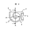
図2は本発明の一参考例を示す副通路構造の縦断面図である。流量計測素子3を内部に有する副通路7は連続的な曲面にて約360°渦巻状に迂回している。流量計測素子3は副通路が約180°迂回した近傍の副通路7ほぼ中央部に設置され、副通路入口部9は吸気通路を流れる空気流に垂直方向に、また副通路出口部10は副通路7が約360°迂回した先端の副通路側壁面に開口している。本構造によれば、副通路7内に進入した塵埃等の異物はその自身の持っている速度と質量による慣性力により副通路7外周壁部分に沿うように進行するため、副通路7のほぼ中心付近に設置されている流量計測素子3に衝突することなく、副通路出口部10より再度吸気通路1へ排出される。更に本構造によれば副通路7の迂回は連続的に形成されているため、通路曲折部内周部分の下流で発生する剥離渦の発生も効果的に抑制することが出来、安定したノイズの少ない発熱抵抗体式空気流量計測装置の出力を得ることが可能である。更に本構造では副通路全体の大きさを変えることなく、副通路出口部10の位置を変えることが可能である、これにより副通路入口部9と副通路出口部10の相対距離を変更することが出来る。副通路入口と出口の相対距離は副通路全体の慣性効果を決定する重要な要素であり、これを自由に変更できることにより、自動車用内燃機関の吸気通路内で発生する脈動流の発熱抵抗体式空気流量計測装置に与える影響度を調節することが可能となる。
FIG. 2 is a longitudinal sectional view of a sub passage structure showing one reference example of the present invention. The
図3は図1及び図2に示した副通路7の通路断面形状の一参考例を示している。図3−1は特に形状を考慮しておらず、この場合には副通路7内部に侵入した異物は副通路外周壁面71にほぼ垂直に衝突することとなるため、壁面に衝突した異物は再度副通路中央部方向へ反射してしまう可能性がある。実際にはこの反射と衝突を繰り返しながら徐々に副通路外周壁面に沿うように流れていくのであるが、図3−2〜図3−4では副通路外周壁面の形状を考慮することにより、異物を効果的に副通路最外周部へガイドすることを目的としている。図3−2は副通路外周壁面71を半円形状としている。図3−3は副通路外周壁面71と副通路側壁面72の接合部の片側に面取りを設け、また図3−4は副通路外周壁面71と副通路側壁面72の接合部の両側に面取りを設けている。何れの構造でも、副通路外周壁面71に衝突した塵埃等の異物は壁面の形成する角度によってより副通路最外周部方向へ反射することとなり、より効果的に異物を副通路最外周部へ集めることが可能となる。
FIG. 3 shows a reference example of the cross-sectional shape of the
図4は図2に示した副通路構造を一部変更した一参考例の縦断面図である。図2に対して、流量計測素子3の副通路内空気流における下流側の副通路側壁面に副通路出口部10の開口面積に対して1/2以下の面積の通気孔11を設置している。本構造によれば、副通路7の持っている慣性効果を効果的に調節することが可能となり、自動車用内燃機関の吸気通路内で発生する脈動流の発熱抵抗体式空気流量計測装置に与える影響度を調節することが可能となる。更に、本渦巻状副通路構造では、静止空気状態では副通路7内部に水が溜まりやすいと言う欠点があるが、この通気孔11により副通路内に進入した水は静止空気状態でも効果的に副通路7外部に排出される。
4 is a longitudinal sectional view of a reference example in which the sub passage structure shown in FIG. 2 is partially changed. With respect to FIG. 2,
図5及び図6は図1及び図2に示した通路構造の一部を変更した一参考例の縦断面図である。何れの例も吸気通路内を流れる空気流に対する副通路7の最下流部分でその外周壁面から曲率の接線方向に高さ1mm程度の通気孔を設けている。本実施例によれば、副通路7の迂回構造によりその外周壁部分に集められた塵埃等の異物は効果的に通気孔より吸気通路1へ排出され、流量計測素子3が設置されている部分へは到達することなく、よりいっそう流量計測素子の経時変化及び破損等の発生を押さえることが可能となる。本構造では副通路7断面積と通気孔11断面積の比を10:1以下とすることで、副通路7の持つ性能を殆ど損なうことなく、前記異物排出を効果的に行うことが可能である。更に、本通気孔は副通路7内へ静止空気状態で水等が溜まりやすいと言う欠点も同時に解消することが可能である。
5 and 6 are longitudinal sectional views of a reference example in which a part of the passage structure shown in FIGS. 1 and 2 is changed. In any example, a vent hole having a height of about 1 mm is provided in the tangential direction of curvature from the outer peripheral wall surface at the most downstream portion of the sub-passage 7 with respect to the airflow flowing in the intake passage. According to the present embodiment, the foreign matter such as dust collected on the outer peripheral wall portion by the bypass structure of the
図7は本発明の一実施例を示す副通路構造の縦断面図である。副通路7は吸気通路1内部を流れる空気流に垂直に開口した副通路入口部9と吸気通路1内部を流れる空気流と平行につまり、副通路側壁面72に開口した副通路出口部10を有している。更に副通路7はその最底部にて180°迂回しており、流量計測素子3は副通路7の迂回部下流側つまり副通路出口部10の形成される側に設置されている。更に副通路7における最底部の副通路入口部9よりの投影面には一定の角度を持った第一縦通路底部傾斜面12が形成され、この傾斜面12の先端部には通気孔11が形成される。本構造によれば副通路7に侵入した塵埃等の異物はその自身の持っている速度と重量により、副通路最底部迂回部でも直進しようとして、第一縦通路底部傾斜面12に衝突する。この時塵埃等の異物はその速度ベクトル方向と傾斜面の角度により通気孔11方向へ反射し、副通路7外へ排出される。
FIG. 7 is a longitudinal sectional view of a sub passage structure showing an embodiment of the present invention. The
図8は図7の実施例に対し、副通路7の高さ寸法を小さくするために第一縦通路底部傾斜面の形状を工夫した一実施例であり、形状の持つ効果及び作用は図8の実施例と同一である。
FIG. 8 shows an embodiment in which the shape of the inclined surface of the bottom of the first vertical passage is devised in order to reduce the height dimension of the
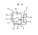
図9及び図10は図7の実施例に対し第二横通路76の構成を変えた一実施例であり、副通路7内に進入した異物に対する効果及び作用は図7の実施例と同様である。図11は参考例の効果を確認するために実施したCAE計算結果の一例である。実線は通路壁面、点線は空気中のダストの軌跡を示す。副通路入口部9より侵入したダストは副通路外周壁面71に衝突−反射を繰り返しながら徐々に副通路外周壁面71に沿って進行していくことが確認される。尚、壁を横切る粒子は出口(入口)を出た粒子である。
9 and 10 show an embodiment in which the configuration of the second
図12は本発明の効果を確認するために実施したCAE計算結果の一例である。実線は通路壁面、点線は空気中のダストの軌跡を示す。副通路入口部9より侵入したダストは直線的に進行し、第一縦通路底部傾斜面12に衝突する。その後ダストは傾斜面の角度により通気孔11方向に反射し、副通路7外へ排出されることが確認できる。
FIG. 12 is an example of CAE calculation results performed to confirm the effect of the present invention. The solid line shows the passage wall surface, and the dotted line shows the locus of dust in the air. Dust that has entered from the
1…内燃機関の吸気通路、2…モジュールハウジング、3…流量計測素子、4…電子回路、5…モジュールフランジ、6…コネクタ、7…副通路、8…副通路最底部迂回部、9…副通路入口部、10…副通路出口部、11…通気孔、12…第一縦通路底部傾斜面、
71…副通路外周壁面、72…副通路側壁面、73…第一縦通路、74…第二縦通路、
75…第一横通路、76…第二横通路。
DESCRIPTION OF
71 ... Sub-passage outer peripheral wall surface, 72 ... Sub-passage side wall surface, 73 ... First longitudinal passage, 74 ... Second longitudinal passage,
75: first lateral passage, 76: second lateral passage.
Claims (9)
前記通路は、主空気の上流側に向けて開口する入口と、前記入口に対して主空気の流れ方向の下流側に位置し前記吸気通路に連通させる通気孔と、前記入口と前記通気孔とを連通し主空気の流れ方向と平行な部分を有する第一通路と、前記第一通路における主空気の流れ方向と平行な通路部分から分岐して設けられ途中に曲がり部を有する分岐通路と、を備え、
前記分岐通路は、前記第一の通路内を流れる空気流のうち前記吸気通路内を流れる主空気と平行な流れの一部を前記分岐通路に取り込むように設けられ、
前記計測素子を前記分岐通路に設置したことを特徴とする空気流量測定装置。 A measuring element for measuring an air flow rate, an electronic circuit electrically connected to the measuring element, a housing that forms a passage and accommodates the measuring element, and is attached to an intake passage through which main air flows. An air flow measuring device,
The passage includes an inlet that opens toward the upstream side of the main air, a vent hole that is located downstream of the inlet in the flow direction of the main air and communicates with the intake passage, the inlet and the vent hole, A first passage having a portion parallel to the flow direction of the main air, a branch passage provided by branching from a passage portion parallel to the flow direction of the main air in the first passage, and having a bent portion in the middle, With
The branch passage is provided so that a part of a flow parallel to the main air flowing in the intake passage among the air flow flowing in the first passage is taken into the branch passage,
An air flow rate measuring apparatus, wherein the measuring element is installed in the branch passage.
前記第一通路の前記通気孔が設けられている側の通路に傾斜面を設けたことを特徴とする空気流量測定装置。 In claim 1,
An air flow rate measuring device characterized in that an inclined surface is provided in a passage on the side of the first passage where the vent hole is provided .
前記傾斜面は前記第一の通路の片側に設けられたことを特徴とする空気流量測定装置。 In claim 2,
The air flow measuring device according to claim 1, wherein the inclined surface is provided on one side of the first passage.
前記傾斜面は前記第一の通路の両側に設けられたことを特徴とする空気流量測定装置。 In claim 2,
The air flow measuring device according to claim 1, wherein the inclined surfaces are provided on both sides of the first passage.
前記計測素子は前記曲がり部よりも下流側の前記分岐通路に設置されたことを特徴とする空気流量測定装置。 In claim 1,
The air flow rate measuring device according to claim 1, wherein the measuring element is installed in the branch passage on the downstream side of the bent portion.
前記計測素子の下流側の前記分岐通路に別の曲がり部が設けられたことを特徴とする空気流量測定装置。 In claim 5,
An air flow rate measuring apparatus, wherein another bent portion is provided in the branch passage on the downstream side of the measuring element.
前記分岐通路は、前記第一の通路に対して180°の方向に延在することを特徴とする空気流量測定装置。 In claim 1,
The air flow measuring device according to claim 1, wherein the branch passage extends in a direction of 180 ° with respect to the first passage.
前記分岐通路は前記電子回路と前記第一の通路との間のハウジングに設けられたことを特徴とする空気流量測定装置。 In claim 1,
The air flow measuring device according to claim 1, wherein the branch passage is provided in a housing between the electronic circuit and the first passage.
前記ハウジングは測定対象空気が流れる主通路中に挿入設置され、
前記分岐通路の出口は前記主通路の流れに平行に開口したことを特徴とする空気流量測定装置。 In any one of Claim 1 to 8,
The housing is inserted and installed in a main passage through which air to be measured flows ,
The outlet of the branch passage is opened in parallel with the flow of the main passage.
Priority Applications (1)
| Application Number | Priority Date | Filing Date | Title |
|---|---|---|---|
| JP2005035366A JP4512499B2 (en) | 2005-02-14 | 2005-02-14 | Air flow measurement device |
Applications Claiming Priority (1)
| Application Number | Priority Date | Filing Date | Title |
|---|---|---|---|
| JP2005035366A JP4512499B2 (en) | 2005-02-14 | 2005-02-14 | Air flow measurement device |
Related Parent Applications (1)
| Application Number | Title | Priority Date | Filing Date |
|---|---|---|---|
| JP2000185907A Division JP3716163B2 (en) | 2000-06-16 | 2000-06-16 | Air flow measurement device |
Publications (3)
| Publication Number | Publication Date |
|---|---|
| JP2005128038A JP2005128038A (en) | 2005-05-19 |
| JP2005128038A5 JP2005128038A5 (en) | 2007-02-01 |
| JP4512499B2 true JP4512499B2 (en) | 2010-07-28 |
Family
ID=34651195
Family Applications (1)
| Application Number | Title | Priority Date | Filing Date |
|---|---|---|---|
| JP2005035366A Expired - Lifetime JP4512499B2 (en) | 2005-02-14 | 2005-02-14 | Air flow measurement device |
Country Status (1)
| Country | Link |
|---|---|
| JP (1) | JP4512499B2 (en) |
Cited By (1)
| Publication number | Priority date | Publication date | Assignee | Title |
|---|---|---|---|---|
| JP2017062171A (en) * | 2015-09-25 | 2017-03-30 | 日立オートモティブシステムズ株式会社 | Main air passage configuration member |
Families Citing this family (8)
| Publication number | Priority date | Publication date | Assignee | Title |
|---|---|---|---|---|
| JP5010877B2 (en) * | 2006-08-31 | 2012-08-29 | 日立オートモティブシステムズ株式会社 | Thermal gas flow measuring device |
| JP4488031B2 (en) | 2007-06-14 | 2010-06-23 | 株式会社デンソー | Air flow measurement device |
| JP5273024B2 (en) * | 2009-11-27 | 2013-08-28 | 株式会社デンソー | Air flow measurement device |
| JP5170209B2 (en) | 2010-10-28 | 2013-03-27 | 株式会社デンソー | Flow measuring device |
| JP5408195B2 (en) | 2011-07-19 | 2014-02-05 | 株式会社デンソー | Air flow measurement device |
| JP5799682B2 (en) | 2011-09-05 | 2015-10-28 | 株式会社デンソー | Air flow measurement device |
| JP5729365B2 (en) * | 2012-09-25 | 2015-06-03 | 株式会社デンソー | Flow measuring device |
| JP2015068794A (en) * | 2013-09-30 | 2015-04-13 | 日立オートモティブシステムズ株式会社 | Thermal type flowmeter |
Citations (5)
| Publication number | Priority date | Publication date | Assignee | Title |
|---|---|---|---|---|
| JPS54122148A (en) * | 1978-03-15 | 1979-09-21 | Kankiyou Rikagaku Kenkiyuushiy | Mass flow meter |
| WO1999053274A1 (en) * | 1998-04-08 | 1999-10-21 | Robert Bosch Gmbh | Measuring device for measuring the mass of a medium flowing in a line |
| JP2001004420A (en) * | 1999-06-21 | 2001-01-12 | Ngk Spark Plug Co Ltd | Measuring apparatus of flow rate and flow velocity |
| JP2001174305A (en) * | 1999-10-06 | 2001-06-29 | Ngk Spark Plug Co Ltd | Flow and flow velocity measuring device |
| JP3716163B2 (en) * | 2000-06-16 | 2005-11-16 | 株式会社日立製作所 | Air flow measurement device |
-
2005
- 2005-02-14 JP JP2005035366A patent/JP4512499B2/en not_active Expired - Lifetime
Patent Citations (6)
| Publication number | Priority date | Publication date | Assignee | Title |
|---|---|---|---|---|
| JPS54122148A (en) * | 1978-03-15 | 1979-09-21 | Kankiyou Rikagaku Kenkiyuushiy | Mass flow meter |
| WO1999053274A1 (en) * | 1998-04-08 | 1999-10-21 | Robert Bosch Gmbh | Measuring device for measuring the mass of a medium flowing in a line |
| JP2002506528A (en) * | 1998-04-08 | 2002-02-26 | ローベルト ボツシユ ゲゼルシヤフト ミツト ベシユレンクテル ハフツング | Measuring device for measuring the mass of a flowing medium flowing in a pipe |
| JP2001004420A (en) * | 1999-06-21 | 2001-01-12 | Ngk Spark Plug Co Ltd | Measuring apparatus of flow rate and flow velocity |
| JP2001174305A (en) * | 1999-10-06 | 2001-06-29 | Ngk Spark Plug Co Ltd | Flow and flow velocity measuring device |
| JP3716163B2 (en) * | 2000-06-16 | 2005-11-16 | 株式会社日立製作所 | Air flow measurement device |
Cited By (1)
| Publication number | Priority date | Publication date | Assignee | Title |
|---|---|---|---|---|
| JP2017062171A (en) * | 2015-09-25 | 2017-03-30 | 日立オートモティブシステムズ株式会社 | Main air passage configuration member |
Also Published As
| Publication number | Publication date |
|---|---|
| JP2005128038A (en) | 2005-05-19 |
Similar Documents
| Publication | Publication Date | Title |
|---|---|---|
| JP3716163B2 (en) | Air flow measurement device | |
| JP4512499B2 (en) | Air flow measurement device | |
| JP5178388B2 (en) | Air flow measurement device | |
| KR100880549B1 (en) | Device for determining at least one parameter of a flowing medium | |
| JP5178148B2 (en) | Heating resistor type air flow measuring device | |
| JP5646030B1 (en) | Flow measuring device | |
| JPH11248505A (en) | Apparatus for measuring flow rate of medium flowing through duct | |
| JP5168223B2 (en) | Air flow measurement device | |
| JP4934198B2 (en) | Plug-in sensor with optimized outflow | |
| JP4170900B2 (en) | Gas flow measuring device | |
| JP3709385B2 (en) | Gas flow measuring device for internal combustion engine | |
| JP6289585B1 (en) | Flow measuring device | |
| US20190242321A1 (en) | Air flow rate measuring device | |
| JP3848934B2 (en) | Air flow measurement device | |
| JP4106224B2 (en) | Flow measuring device | |
| JP2022084957A (en) | Physical quantity measuring device | |
| KR100866268B1 (en) | Device for measuring air flow, comprising a device for separating foreign particles | |
| JP6069504B2 (en) | Temperature / humidity sensor | |
| JP3797210B2 (en) | Flow measuring device | |
| JP2006506625A (en) | Apparatus for measuring at least one parameter of a medium flowing in a conduit | |
| JP2006522921A (en) | Apparatus for measuring at least one parameter of a medium flowing in a pipeline | |
| JP3602762B2 (en) | Flow measurement device | |
| JP2003315116A (en) | Flow measuring device | |
| JP2004012274A (en) | Flow measuring apparatus | |
| JP3345994B2 (en) | Engine intake system |
Legal Events
| Date | Code | Title | Description |
|---|---|---|---|
| RD02 | Notification of acceptance of power of attorney |
Free format text: JAPANESE INTERMEDIATE CODE: A7422 Effective date: 20060512 |
|
| RD04 | Notification of resignation of power of attorney |
Free format text: JAPANESE INTERMEDIATE CODE: A7424 Effective date: 20060512 |
|
| A521 | Written amendment |
Free format text: JAPANESE INTERMEDIATE CODE: A523 Effective date: 20061207 |
|
| A621 | Written request for application examination |
Free format text: JAPANESE INTERMEDIATE CODE: A621 Effective date: 20061207 |
|
| A711 | Notification of change in applicant |
Free format text: JAPANESE INTERMEDIATE CODE: A712 Effective date: 20091214 |
|
| A521 | Written amendment |
Free format text: JAPANESE INTERMEDIATE CODE: A523 Effective date: 20091217 |
|
| A131 | Notification of reasons for refusal |
Free format text: JAPANESE INTERMEDIATE CODE: A131 Effective date: 20100119 |
|
| A521 | Written amendment |
Free format text: JAPANESE INTERMEDIATE CODE: A523 Effective date: 20100323 |
|
| TRDD | Decision of grant or rejection written | ||
| A01 | Written decision to grant a patent or to grant a registration (utility model) |
Free format text: JAPANESE INTERMEDIATE CODE: A01 Effective date: 20100420 |
|
| A01 | Written decision to grant a patent or to grant a registration (utility model) |
Free format text: JAPANESE INTERMEDIATE CODE: A01 |
|
| A61 | First payment of annual fees (during grant procedure) |
Free format text: JAPANESE INTERMEDIATE CODE: A61 Effective date: 20100510 |
|
| FPAY | Renewal fee payment (event date is renewal date of database) |
Free format text: PAYMENT UNTIL: 20130514 Year of fee payment: 3 |
|
| R150 | Certificate of patent or registration of utility model |
Ref document number: 4512499 Country of ref document: JP Free format text: JAPANESE INTERMEDIATE CODE: R150 Free format text: JAPANESE INTERMEDIATE CODE: R150 |
|
| FPAY | Renewal fee payment (event date is renewal date of database) |
Free format text: PAYMENT UNTIL: 20130514 Year of fee payment: 3 |
|
| EXPY | Cancellation because of completion of term |